

Page 1
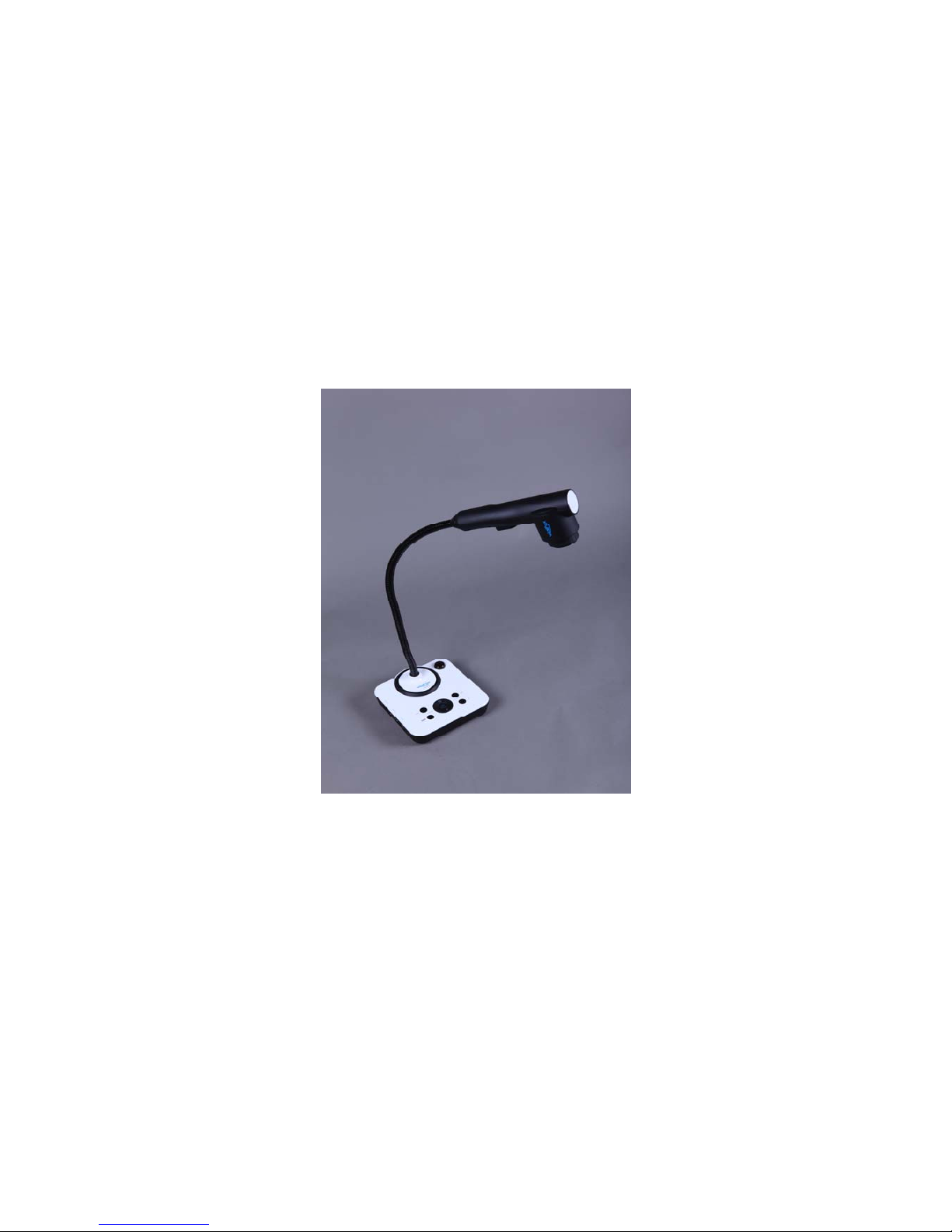
Vidifox
®
Document Camera
GV 200
USER MANUAL
Please read this manual carefully before operating the document camera and keep it for reference.
1
Page 2
PRECAUTIONS
NOTICES: PLEASE READ CAREFULLY BEFORE USE
Use the document camera under the rated electric conditions.
Do not place the document camera on any unstable surface. It may fall and cause injures
or damages.
Do not place this device directly under sunlight or near heaters.
Do not place this device near water.
Keep the camera away from acid or alkali gas.
Do not place this document camera in humid, dusty, windy or vibrant locations.
The recommended operating environment is:
Temperature: 0ºC--45ºC (32ºF-113ºF)
Humidity: less than 75%
Always unplug BEFORE cleaning the device. Use a dam p soft-cloth fo r cleaning. D o not
use volatile solvent.
When this equipment functions abnormally, such as smoke, smell, noise, immediately
unplug and call for professional assistance.
Unplug the document camera or shut off the power when not in use.
Legal Notice
FCC Part 15
This device complies with Part 15 of the FCC Rules. Operation of this product is subject to the
following two conditions: (1) this device may not cause harmful interference, and (2) this device
must accept any interference received, including interference that may cause undesired operation.
Compilation and Publication Notice
This manual has been compiled and published to cover the latest product’s descript i ons and
specifications. The contents of this manual and the specifications of this product are subject to
change without notice.
Wanin USA reserves the right to make changes without notice in the specifications and materials
contained herein and shall not be responsible for any damages (including consequential) caused by
reliance on the materials presented, including but not limited to typographical and other errors
relating to the publication.
©2011 Wanin USA Inc. All Rights Reserved.
2
Page 3

USER MANUAL.......................................................................................1
1. PARTS IDENTIFICATION.................................................................4
2. CONTROL PANEL..............................................................................5
3. INPUTS AND OUTPUTS ....................................................................5
4. REMOTE CONTROL .........................................................................6
5. CONNECTIONS...................................................................................8
5.1. COMPUTER CONNECTION...........................................................................................8
5.2. VGA OUTPUT CONNECTION........................................................................................8
6. COMMUNICATE WITH COMPUTER............................................9
6.1. COMPUTER REQUIREMENTS......................................................................................9
6.2. USB CAMERA..................................................................................................................9
7. FEATURES .........................................................................................15
LIGHT.....................................................................................................................................
15
ZOOM IN AND ZOOM OUT................................................................................................15
FOCUS ADJUSTMENT.........................................................................................................15
BRIGHTNESS ADJUSTMENT.............................................................................................15
WHITE BALANCE ADJUSTMENT.....................................................................................15
TEXT/PICTURE MODE........................................................................................................16
IMAGE FREEZE....................................................................................................................16
IMAGE MIRROR...................................................................................................................16
SPLIT SCREEN......................................................................................................................16
IMAGE SAVE.........................................................................................................................16
IMAGE RECALL...................................................................................................................16
USB 2.0 PORT........................................................................................................................16
USB IMAGE CAPTURE AND VIDEO RECORDING.........................................................17
8. SPECIFICATION...............................................................................18
9. TROUBLE-SHOOTING....................................................................19
10. PACKING LIST................................................................................27
3
Page 4
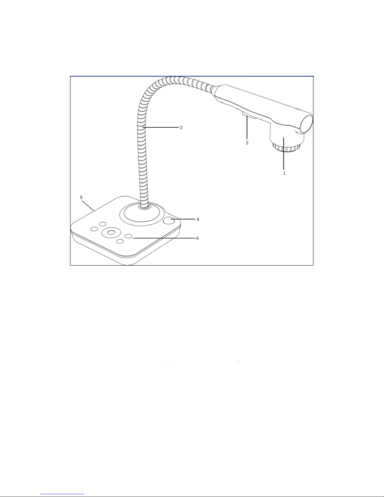
1. PARTS IDENTIFICATION
1. Camera
2. LED light box
3. Goose neck
4. Remote control IR receiver
5. Side panel
6. Control panel
4
Page 5
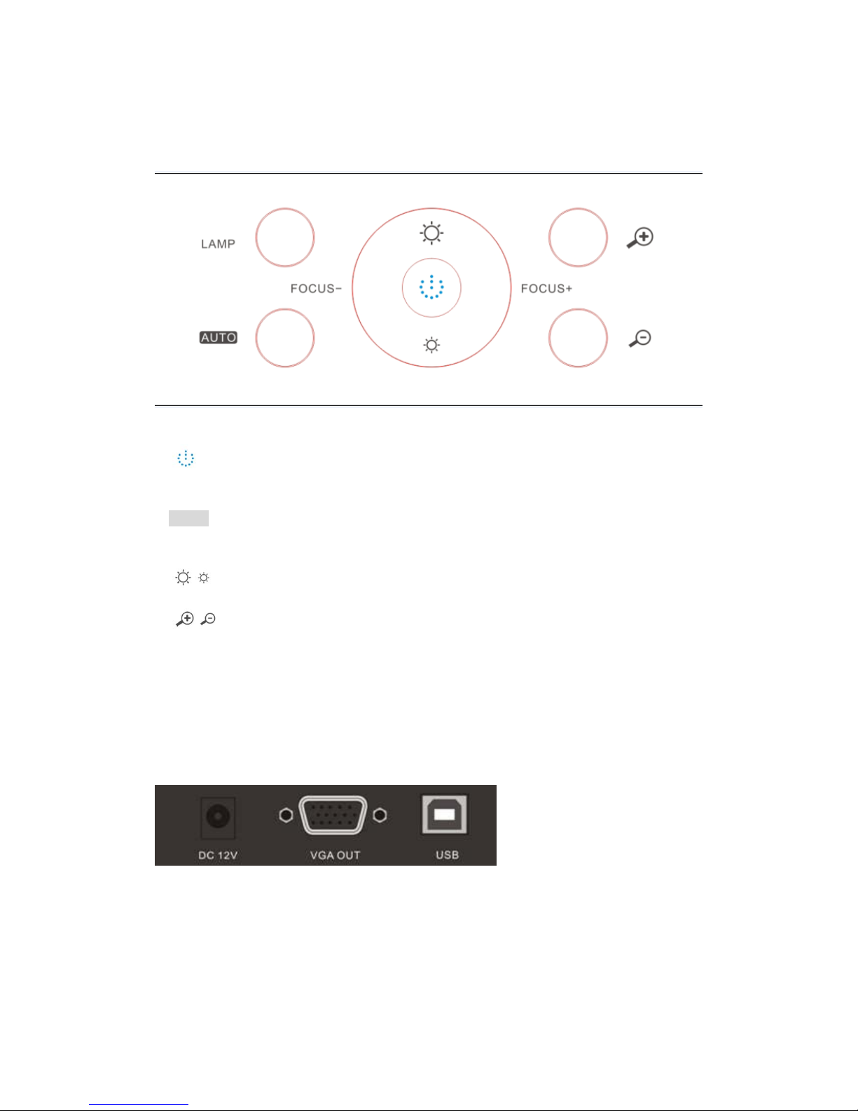
2. CONTROL PANEL
1.
POWER: Turn the power on/off.
2. LAMP: Turn the LED light on/off.
3. AUTO: Carry out auto focus, color adjustment and white balance.
4. FOCUS+/-: Adjust focus manually, focus far and focus near.
5.
BRIGHT+/-: Adjust im age brig ht ness manually.
6.
ZOOM+/-: Image zoom in and zoom out.
3. INPUTS AND OUTPUTS
1. DC 12V: Power input.
2. VGA OUT: V G A (RGB) signal output(15 pin D-SUB).
3. USB: Capture image into a connected computer via provided software
5
Page 6
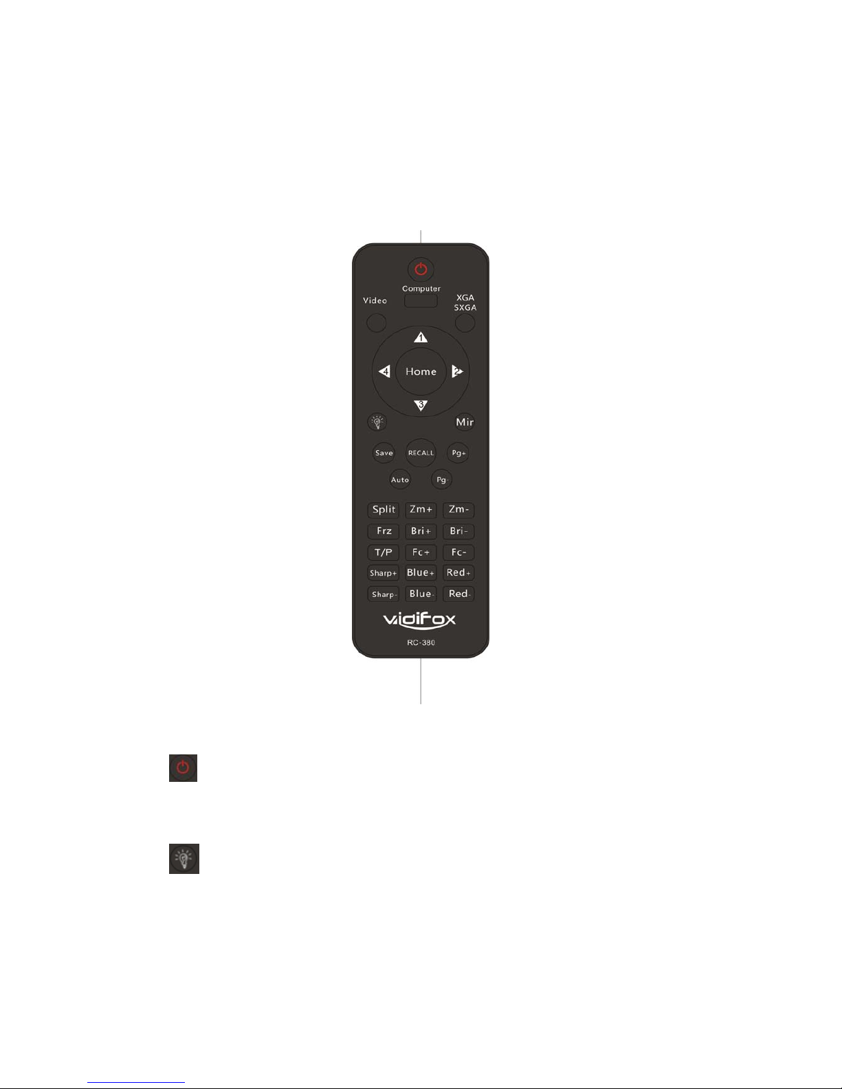
4. REMOTE CONTROL
1.
: Turn the document camera on or off.
2. Save: Capture the image in display to internal memory.
3. Recall: Image recall mode enabled, display the saved images.
4.
Lamp: Turn the LED light on/off.
5. Split: Split screen, enable the comparison between the frozen image and live image.
6. Pg- (Page down): Saved image page down when image recall mode is enabled.
7. Pg+ (Page up): Saved image page up when image recall mode is enabled.
8. Mir (Mirror): Output right-and-left, up-and-down mirror image.
6
Page 7

9. Frz (Freeze): Freeze/unfreeze the image.
10. T/P: Switch the output image between text mode and picture mode.
11. Red+/-: Image chroma control (red).
12. Blue+/-: Image chroma control (blue).
13. SXGA/XGA: Switch the output signal between XGA and SXGA.
14. Home: Activate when it makes the focus curve and optics center adjust.
15. Sharp+/-: Image sharpness control.
16. Auto: Carry out auto focus, color adjustment and white balance.
17. Computer: Activate when it makes the focus curve.
18. Video: Activate when it makes the focus curve.
19. Zm+/-: Image zoom in and zoom out control.
20. Fc+/-: Adjust focus manually, focus far and focus near.
21. Bri+/-: Adjust image brightness.
7
Page 8
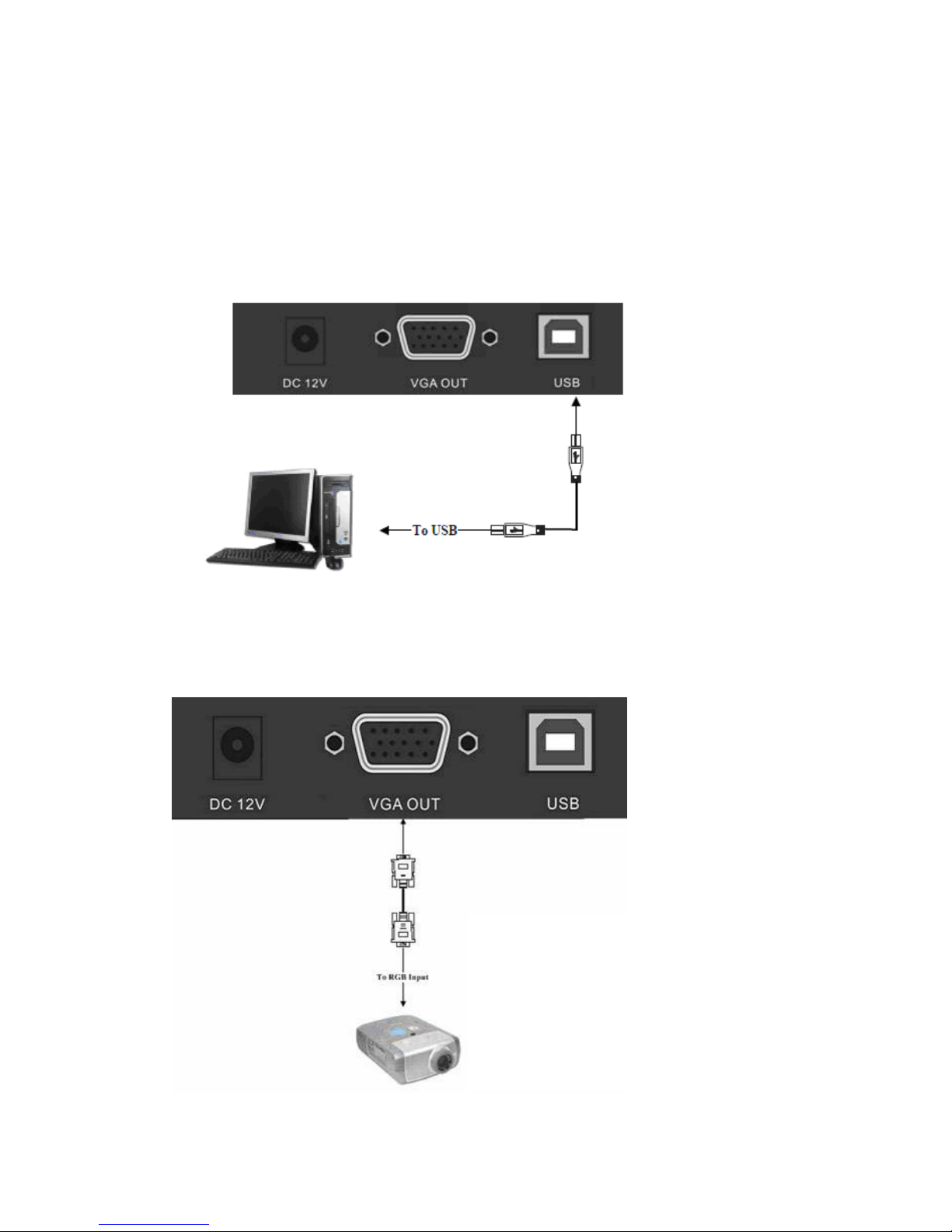
5. CONNECTIONS
5.1. COMPUTER CONNECTION
5.2. VGA OUTPUT CONNECTION
8
Page 9
6. COMMUNICATE WITH COMPUTER
6.1 COMPUTER REQUIREMENTS
The PC's hardware and software configurations shall not be less than the following requirements:
Operating system: Windows XP
CPU: 1.8 GHz
Physical memory: 512M
Video memory: 64M
6.2 USB FUNCTION
、
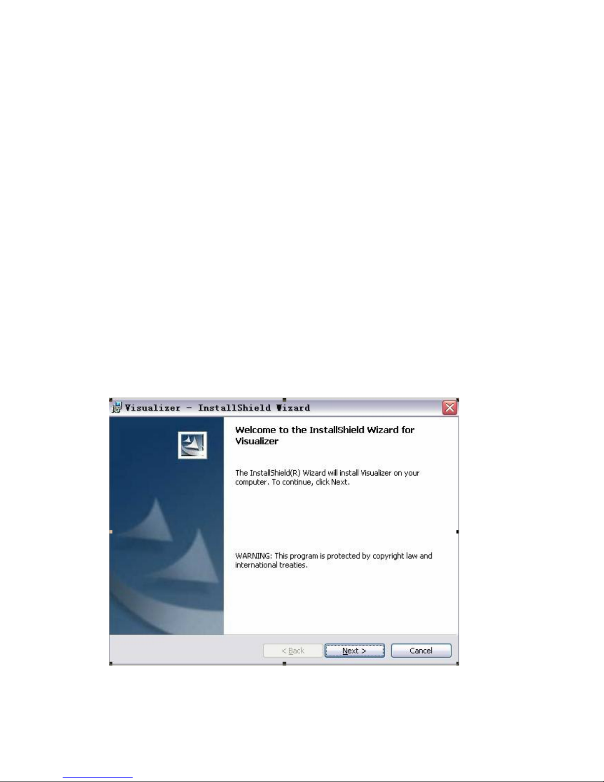
1 SOFTWARE INSTALLATION
Click to run the software installation package, the following dialogue appe ars, clic k " N ext":
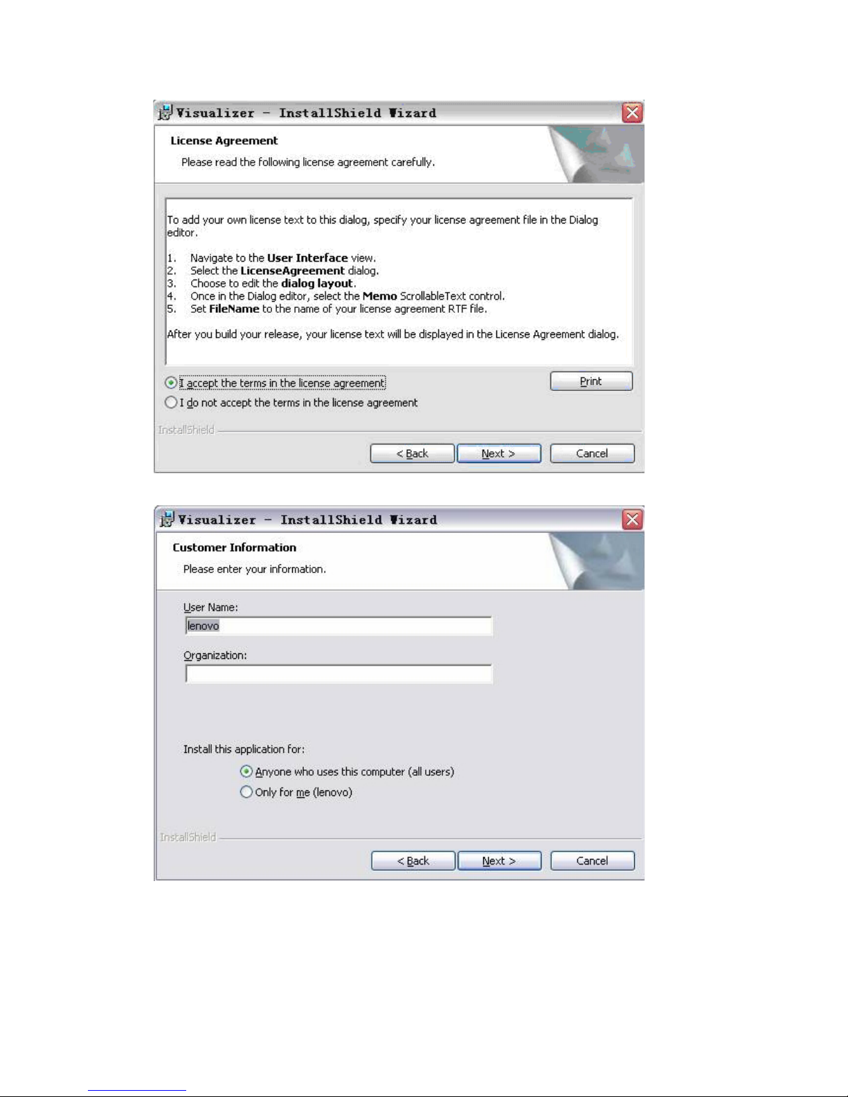
Read the terms, Select "I accept the terms in the license agreement." Click "Next", as the following
figure.
9
Page 10
The following dialogue box appears, click "Next":
The default installation directory is Program Files, C: \ Program Files \, you can select a different
installation directory, as shown:
10
Page 11
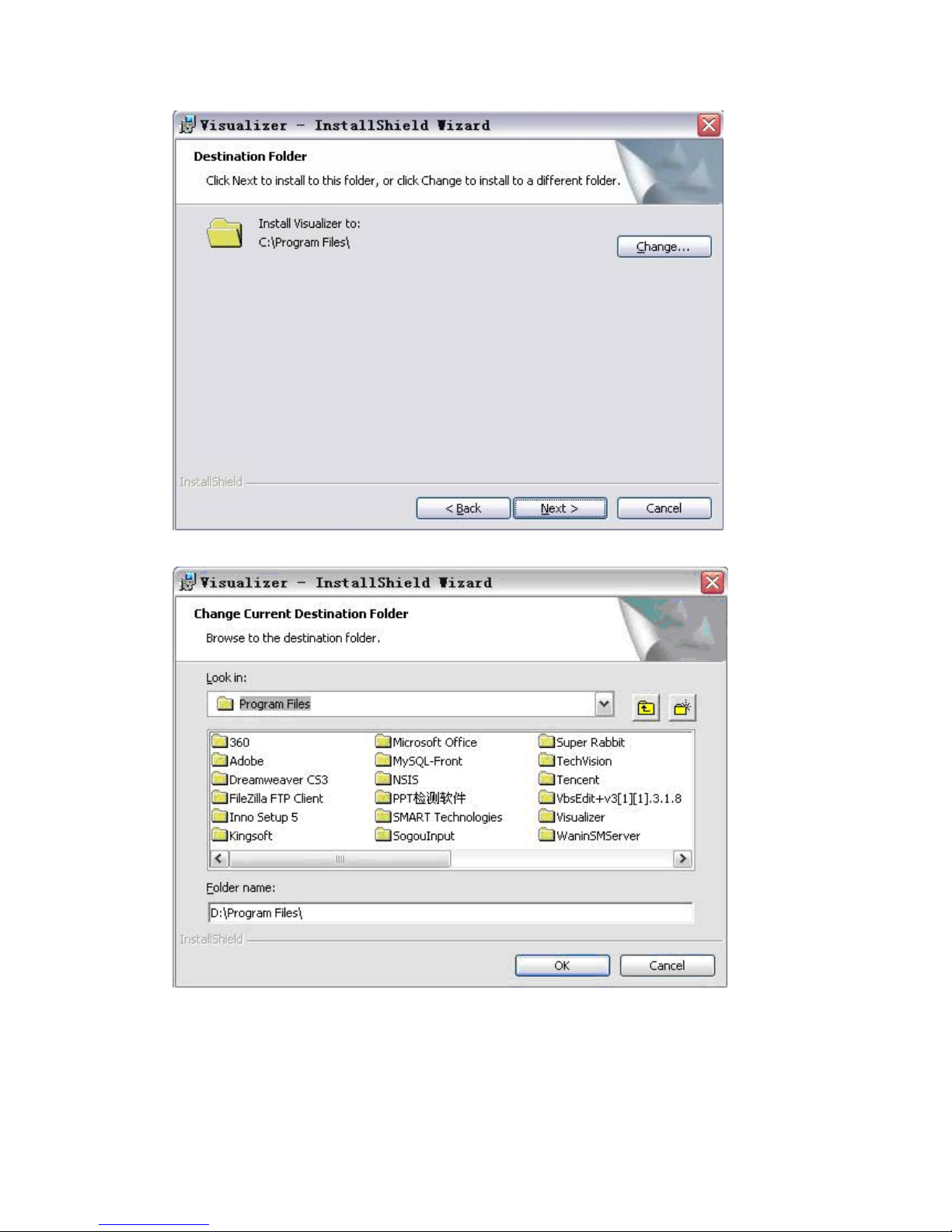
Click "Change" to change the directory, as shown:
Click "OK", the following figure appears. Click "Next".
11
Page 12
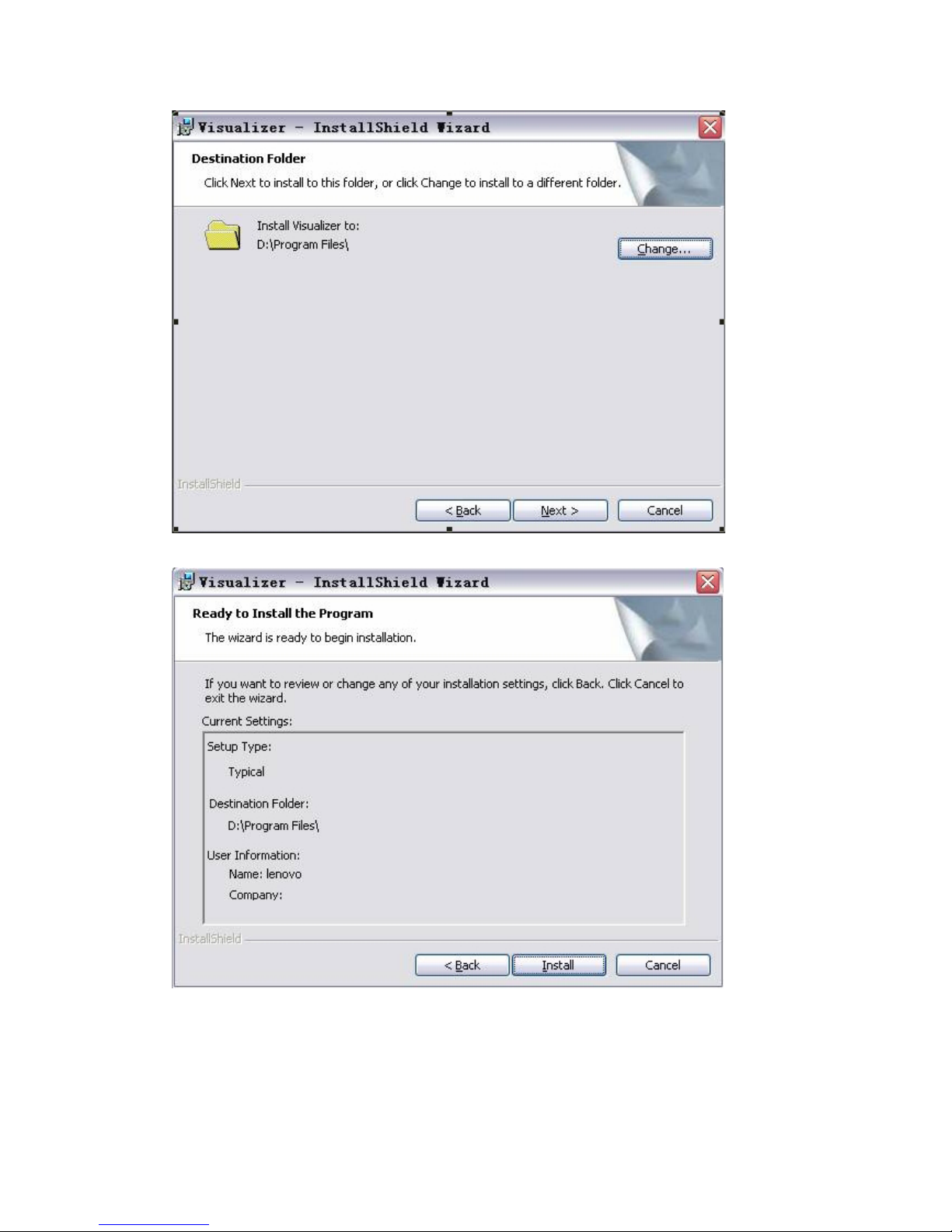
Click "Install" to complete installation, as shown:
Click "Finish” to complete the installation, as shown:
12
Page 13
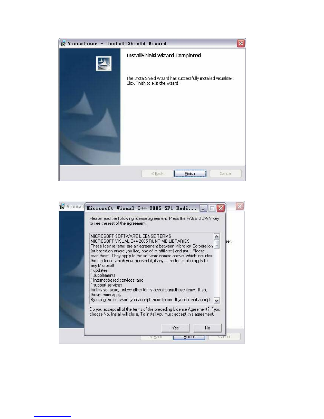
Then you will see the following interface, which is an installation package for 2005 environment.
If your PC already has this installed, click "No" to exit, otherwise, click "Yes" to install it.
13
Page 14
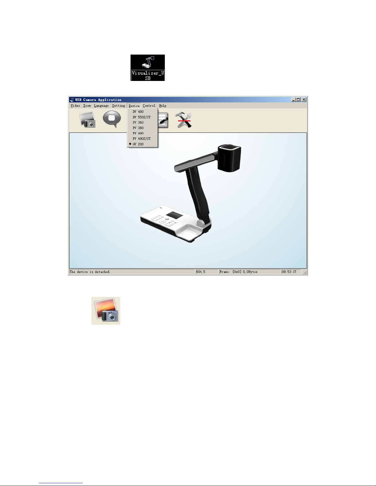
2、SOFTWARE START
Double click the short cut
on the desktop, then click Device, select the right model
number, see below:
IMAGE CAPTURE AND VIDEO RECORDING:
Left click
to capture images. The captured images will be automatically saved into the
default destination folder. The path and file name are displayed in software status bar on th e bottom
of the window. Shown below:
14
Page 15
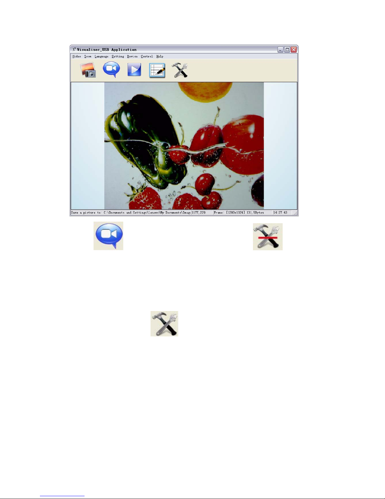
Left click to start recording. The setting button will changes to and does not
work. The detailed information is displ aye d on the s oftware st atus bar i n the bot tom of the window.
The video is automatically saved in the default folder or pre-set folder.
SETTING:
The captured images and recorded videos will be saved into the folders of Images and Videos
respectively, which are created by the system automatically. To set a different path to which the
image/video is be to saved, click
on the left side of the window, a pop up dialog box
appears below.
15
Page 16
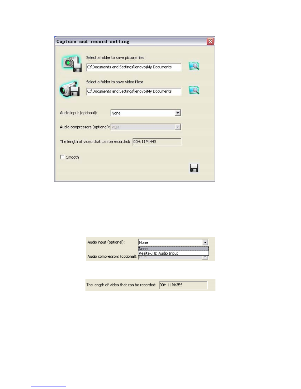
Save the captured images into a different folder
Click the button next to the "select a folder to save picture files" text b ox to set the path for c aptured
images.
Save the recorded video into a different folder and set up parameters for videos
Click the button next to the "Select a folder to save video files:" text box to set the path for videos.
Y ou ca n also change the vide o settings. The Audio input (optional) drop down box offers the options
of recording video with or without sound. Shown below:
The length of video that can be recorded box displays the longest recording time for videos to be
saved in the preset path. Shown below:
Click save to complete setting.
16
Page 17
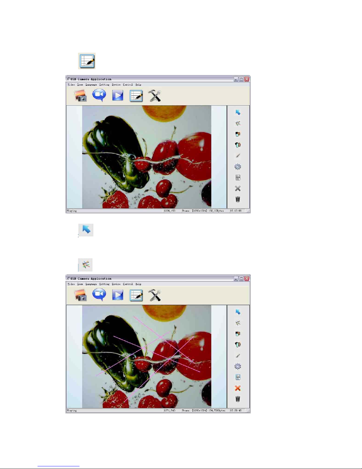
IMAGE MODIFY:
Click
, you will see the interface:
Graphic selection and move
Click to choose a line, circle, rectangle or curve that placed in the image, then move to
another place.
Line
Click to place a beeline in the image, shown as below:
17
Page 18
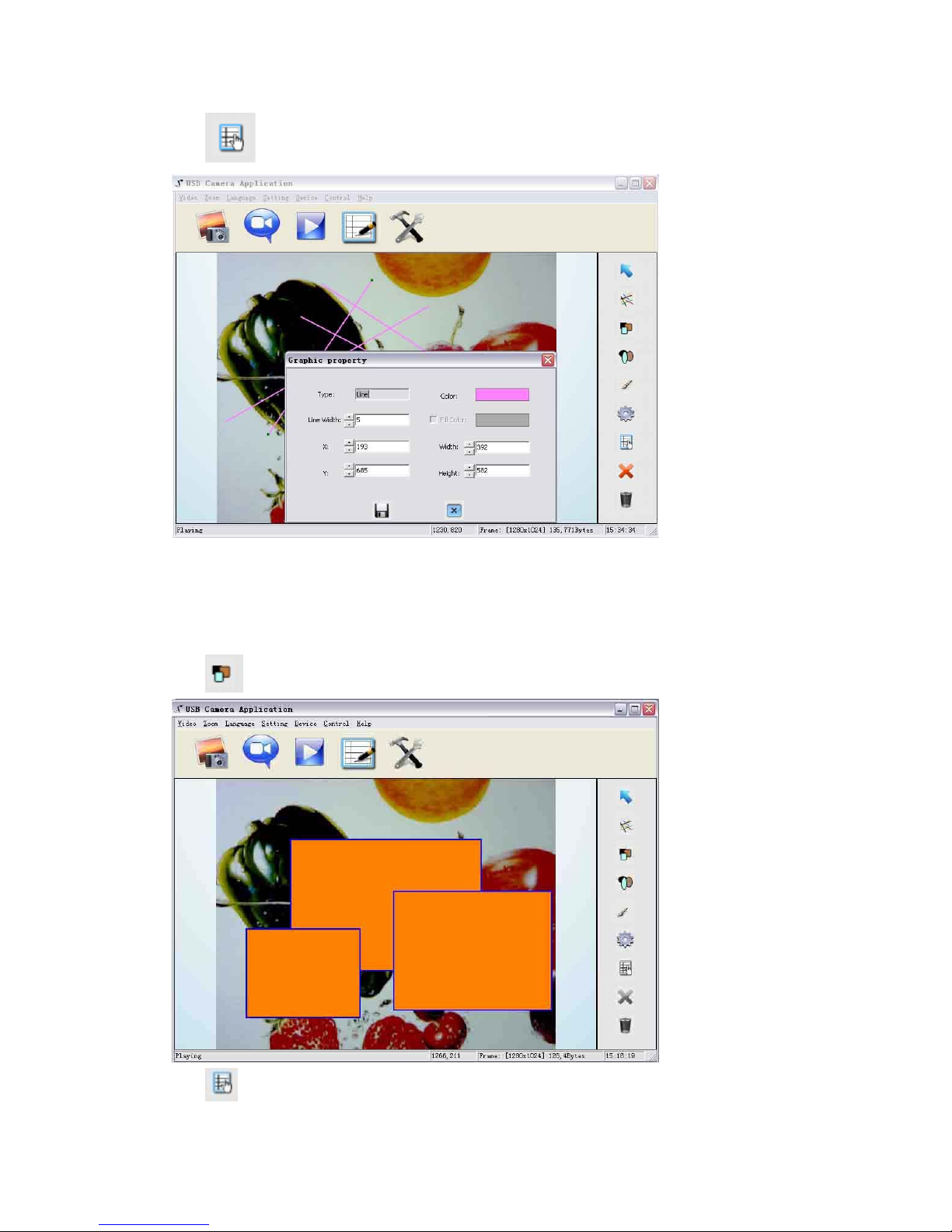
Click to change the setting of the chosen line:
Line width: change the width of the line.
X, Y: change the position of the line.
Color: change the color of the line.
Width, Height: Change the angle of the line.
Rectangle
Click to place a rectangle in the image, shown as below:
Click to change the setting of the chosen rectangle:
18
Page 19
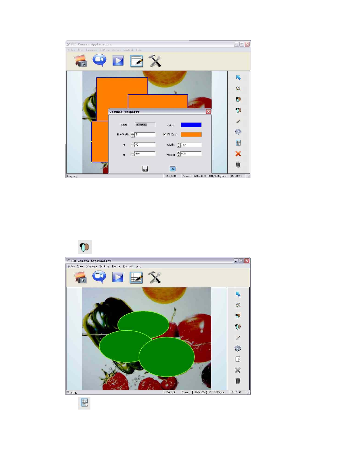
Line width: change the line width of the rectangle.
X, Y: change the position of the rectangle.
Color: change the line color of the rectangle.
Fill Color: Tick it to fill color in the rectangle.
Width, Height: Change the shape of the rectangle by changing the angle of two adjacent lines
of the rectangle.
Circle
Click
to place a circle in the image, shown as below:
Click to change the setting of the chosen circle:
19
Page 20
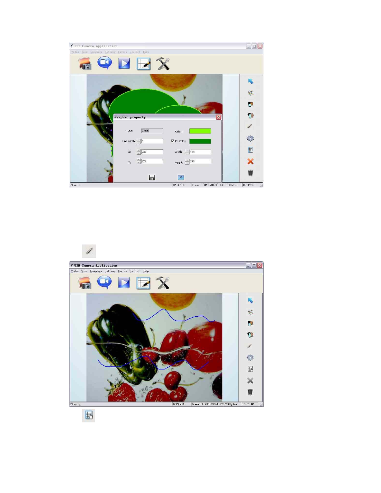
Line width: change the line width of the circle.
X, Y: change the position of the circle.
Color: change the line color of the circle.
Fill Color: Tick it to fill color in the circle.
Width, Height: change the size of the circle.
Curve
Click to place a curve in the image, shown as below:
Click to change the setting of the chosen curve:
20
Page 21
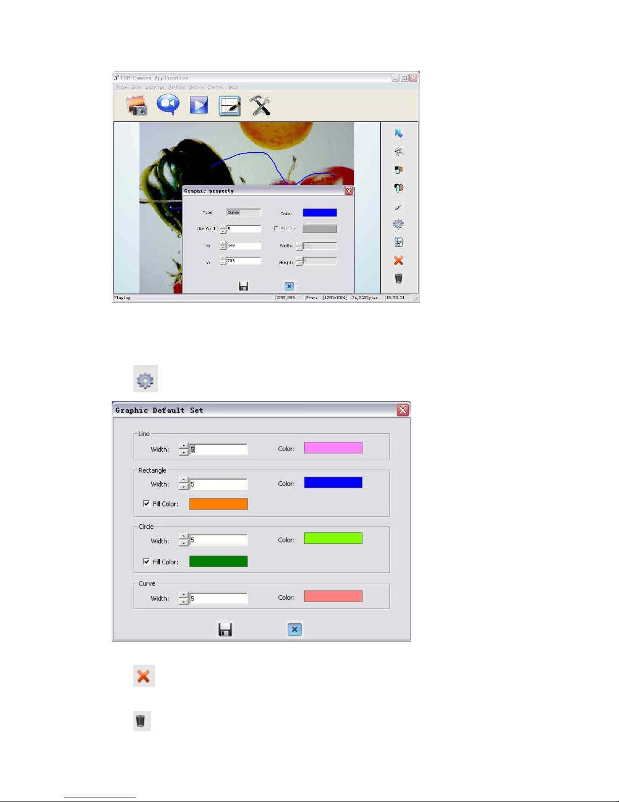
Line width: change the line width of the curve.
X, Y: change the position of the curve.
Color: change the line color of the curve.
Graphic default setting
Click to change the setting of the graphic:
Graphic delete
Click to delete the chosen graphic.
Delete al the graphic
Click to delete all graphic that placed in the image.
21
Page 22

7. FEATURES
LIGHT
The GV200 is an environmentally friendly product, it is RoHS compliant and meets the rigorous
European Union’s requirements for restriction of the use of certain hazardous substances in
electrical and electronic equipment. The lighting box of GV200 adopts eco-friendly, low power
consumption and long lasting LED lamps, which is cool to the touch and mercury free.
ZOOM IN AND ZOOM OUT
8x optical zoom combined with 12x seamless digital zoom, the GV200 enables you to view the
finest details of any objects that are impossible to see with naked eyes. The GV200’s advanced
optical system features high speed auto focus capability that ensures instant auto focus when you
quickly zoom in and out of any object. You can also manually adjust viewing area by pressing
.
FOCUS ADJUSTMENT
When the document camera is turned on, the focus automatically adjusts to the stage, it is not
necessary to readjust the focus if you are only working with flat materials (text, photos, etc.). Only
3D objects require a focus adjustment. Press the “AUTO” button once to auto focus. Press the
"FOCUS+" or "FOCUS-"button to focus manually.
BRIGHTNESS ADJUSTMENT
If the image effect is not satisfactory, you can adjust the brightness to get a better image effect.
Use the
(“BRIGHT +” or “BRIGHT -” ) button to adjust the brightness. To increase the
brightness, press the “BRIGHT +” button. To decrease it, press the “BRIGHT -” button.
WHITE BALANCE ADJUSTMENT
Each time the lighting condition changes, the user should adjust the white balance of the CMOS.
22
Page 23

Press the “AUTO” button to adjust the white balance automatically.
TEXT/PICTURE MODE
The Text enhancement feature provides the option to improve the readability of the text by
improve the contrast of the text image via pressing the “T/P” button.
IMAGE FREEZE
The freeze function allows you to discretely prepare the next image without interrupting current
presentation. Use "Frz" to freeze and unfreeze the image.
IMAGE MIRROR
The mirror function gives you a different perspective of an object.
SPLIT SCREEN
The split screen offers the capability of comparing two images or comparing two different views
of one object side by side.
IMAGE SAVE
The GV200 offers the opportunity of storing 12 images on board. You can recall them by pressing
one of the numerical buttons on the remote control.
IMAGE RECALL
By pressing the “Recall” button, all save d images is d isplayed in the thumbnail index mode for e asy
selection.
USB 2.0 PORT
The USB port can be used to capture still images from the document camera to a computer. No
additional computer hardware is required. In this way, the document camera can be used as a 3-D
scanner for your computer. Connect the document camera to your computer with the supplied
23
Page 24

USB cable. The Visualizer Software is available on the supplied CD-ROM.
USB IMAGE CAPTURE AND VIDEO RECORDING
The GV200 is the document camera equipped with a USB 2.0 image capture and video recording
system. Simply connect the GV200 to a computer, with the software and driver provided, you can
easily preview, capture and save any images on your PC and Mac.
24
Page 25

8. SPECIFICATION
Model GV200
Sensor 1/3" CMOS
Pixels 2 Megapixel
Zoom 8x optical, 12x digital
Frame rate 12
Shooting area Max:16.5"x11.7", Min: 0.1"x0.1"
Focus Auto/manual
Output resolution XGA, SXGA
Resolution(Horizontal) ≥750 TV lines
White balance Auto/manual
Color adjustment Yes
Brightness adjustment Yes
Image capture Yes,12 images
Video recording Yes(via USB)
Image mirror Yes
Image split Yes
Image freeze Yes
Text mode Yes
OSD Yes
USB2.0 Slave×1(USB camera)
Remote control Yes (360°controllable)
Light source LED light box
Kensington lock slot Yes
Operating temperature 32°F ~113°F
Dimensions Setup:17.7"×8.3"×19.7", Folded: 6.7"×8.3"×15.7"
Power supply 12V DC power adapter
Weight(net) 3.97lbs/1.8kg
25
Page 26
9. TROUBLE-SHOOTING:
Symptoms Possible causes/counter-measures
No image 1. Power cord is not properly connected.
2. Cables are not properly connected.
3. Power switch is not turned on.
4. The built-in fuse is broken: Cha nge fuse.
5. Change the output resolution.
Image bending 1. Camera not in right position, adjust the camera.
2. Press the AUTO
Out of focus or blurring
image
1. The object is too close to the lens.
2. Focus is on the top point of zoom, press ZOOM-.
3. Auto-focus is not on: press AUTO again.
4. Fog on the lens in damp climate. It will disappear
gradually when the equipment warms up.
If the problem still remains after checking the above, consult your dealer or authorized service
personally.
26
Page 27
10. PACKING LIST
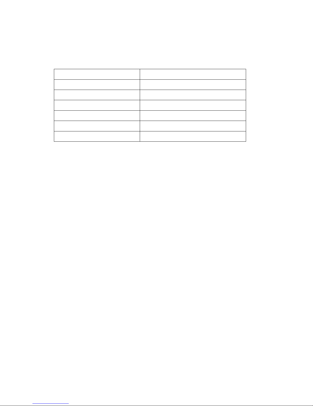
Item Quantity
Power cord 1
Power adaptor(12V/2A) 1
VGA cable 1
USB cable(2.0) 1
Remote control 1
User manual(CD) 1
27
Page 28

28
11. TECHNICAL SUPPORT
Wanin USA is committed to providing highest possible stand of customer service. We can be
reached:
By Phone
Call us at 1-877-369-3130. Our technical support staff provides technical assista nc e from 9:00AM
through 5:00PM Pacific Standard Time, Monday through Friday. Please gather the following
information before calling:
- Product model name(s) and numbers
- Product serial number(s)
- Detailed questions or problem descriptions.
Online
Technical support is also available online at Wanin USA’s web site at www.waninusa.com.
You can enter your questions and concerns through our online form, email us at
WaninUSAInc.
12961RamonaBlvd.,Irwindale,CA91706
TollFree:1‐877‐369‐3130 Fax:626‐609‐3380
E‐mail:[email protected] Web:www.waninusa.com
©2010 Wanin USA Inc. All Rights Reserved.
 Loading...