

Page 1

Call Recorder ISDN
VIDICODE Datacommunicatie BV
POBox 7164
2701 AD Zoetermeer
The Netherlands
Tel. +31 79 3617181
Fax +31 79 3618092
www.vidicode.nl
vidicode@vidicode.nl
Manual
Page 2

2
Call Recorder ISDN Manual - ©2001 - Vidicode Datacommunicatie BV
Page 3

Contents
1 INTRODUCTION ..................................................................................7
1.1 CONNECTING TO RECORD CALLS 8
1.2 M
1.3 T
1.4 S
1.5 S
2 INSTALLING THE CALL RECORDER ..............................................13
2.1 UNPACKING 13
2.2 C
2.3 T
3 CONFIGURING THE CALL RECORDER..........................................19
3.1 LOUDSPEAKER 19
3.2 P
3.3 S
3.4 U
3.5 T
3.6 S
3.7 S
3.8 O
IXING, COMPRESSION AND CAPACITY 8
HE NETWORK INTERFACE AND COMPATIBILITY 9
1.3.1 Network Protocol 9
1.3.2 PC Compatibility 9
ECURITY 10
OME TERMINOLOGY 11
ONNECTING THE CALL RECORDER 13
2.2.1 Connecting the power supply 14
2.2.2 Connecting the S0 buses 14
2.2.3 Connecting external loudspeakers (not compulsory) 14
2.2.4 Connecting the microphone (not compulsory) 15
2.2.5 Connecting to the LAN (not compulsory) 15
URNING ON THE POWER 16
LAYBACK VOLUME 20
PEECH COMPRESSION 20
SE OF THE CRYPTOCARD 20
HE CLOCK 21
ETTING THE PASSWORD 21
ELECTING THE LANGUAGE 22
THER CONFIGURATIONS 22
4 OPERATING THE RECORDER ........................................................23
4.1 RECORDING TELEPHONE CALLS 23
4.2 R
4.3 S
ECORDING WITH THE MICROPHONE 23
4.2.1 Recording 24
EARCHING FOR AND PLAYING OF TELEPHONE CALLS 25
4.3.1 Searching for (Telephone) Recordings 25
4.3.2 Playing the recording 28
Call Recorder ISDN Manual - ©2001 - Vidicode Datacommunicatie BV
3
Page 4

4.3.3 The Function of the Recorder Keys Before and During Playback 28
4.4 S
EARCHING FOR AND PLAYING MICROPHONE RECORDINGS 30
4.4.1 Searching for microphone recordings 30
4.4.2 Playing the microphone recordings 31
4.5 T
4.6 T
HE DISK KEY 32
HE MONITOR 33
5 THE NETWORK INTERFACE ...........................................................35
5.1 THE POSSIBILITIES 35
5.2 C
5.3 U
ONFIGURATION 36
SE OF THE NETWORK INTERFACE 39
5.3.1 The FTP protocol 39
5.3.2 The monitor 40
6 THE CRYPTO CARD OPTION ..........................................................41
6.1 HOW A CRYPTO CARD WORKS 41
6.2 C
6.3 R
6.4 P
HANGING THE CARD CODE 42
ECORDING WITH THE CRYPTO CARD 43
LAYING RECORDINGS WITH THE CRYPTO CARD 43
7 ERASING RECORDINGS ..................................................................45
8 MAINTENANCE .................................................................................47
8.1 CHANGING THE DISK DRIVE 47
8.2 C
HANGING THE BATTERY 47
9 ACCESSORIES..................................................................................49
10 GUARANTEE CONDITIONS ..........................................................51
11 ADDITIONAL INFORMATION ........................................................53
12 INDEX..............................................................................................55
4
Call Recorder ISDN Manual - ©2001 - Vidicode Datacommunicatie BV
Page 5

Call Recorder ISDN Manual - ©2001 - Vidicode Datacommunicatie BV
5
Page 6

6
Call Recorder ISDN Manual - ©2001 - Vidicode Datacommunicatie BV
Page 7

1 Introduction
The Call Recorder ISDN is an audio recorder that has been specially designed to
record telephone conversations from ISDN basic connections (S0 buses). There
are models for 1, 2 and 4 S0 buses which are technically virtually the same. A
Call Recorder ISDN has certain special features: It can record from 1 to 4 ISDN
buses and from 1 microphone. It records digitally
• It starts and stops recording automatically (or manually for microphone
recordings)
• It archives the recordings to facilitate searching
• It highly compresses recordings, resulting in a large storage capacity
• It can interface with computers and networks using the Ethernet interface and
TCP/IP protocol with the built-in FTP server
• It comes with a chip card (IC Card) reader to safeguard security
A Call Recorder is configured to record simultaneously from the signal sources
present:
• 2 recordings per S0 bus, i.e. 8 recordings at the same time
• 1 recording from a microphone
The total number of recordings it can make simultaneously is therefore 9.
The recordings are stored on an internal hard disk. The storage capacity is
expressed in the number of hours of recording time with standard compression.
There are 5 different types of Call Recorder:
Art. 1490 Call Recorder ISDN 1xS0 2 calls, 2600 hours
Art. 1492 Call Recorder ISDN 1xS0 2 calls, 5200 hours
Art. 1494 Call Recorder ISDN 2xS0 4 calls, 5200 hours
Art. 1496 Call Recorder ISDN 2xS0 4 calls, 7800 hours
Art. 1498 Call Recorder ISDN 4xS0 8 calls, 7800 hours
The capacity can be increased or decreased by setting different compression
methods. The capacity is at its lowest when the recorder is set to not use
compression and the ISDN signal is stored mixed but is otherwise unchanged.
The capacity at this setting can be calculated by dividing the capacity indicated
above by a factor of 7.5.
Call Recorder ISDN Manual - ©2001 - Vidicode Datacommunicatie BV
7
Page 8
1.1 Connecting to Record Calls
A Call Recorder ISDN can be used in various ways:
1. As a desktop machine that
usually records one’s own calls.
The smallest type, ISDN1, is
most commonly used for this
purpose. The advantage of this
way of using it is that the
recordings are always available
at one’s own desk.
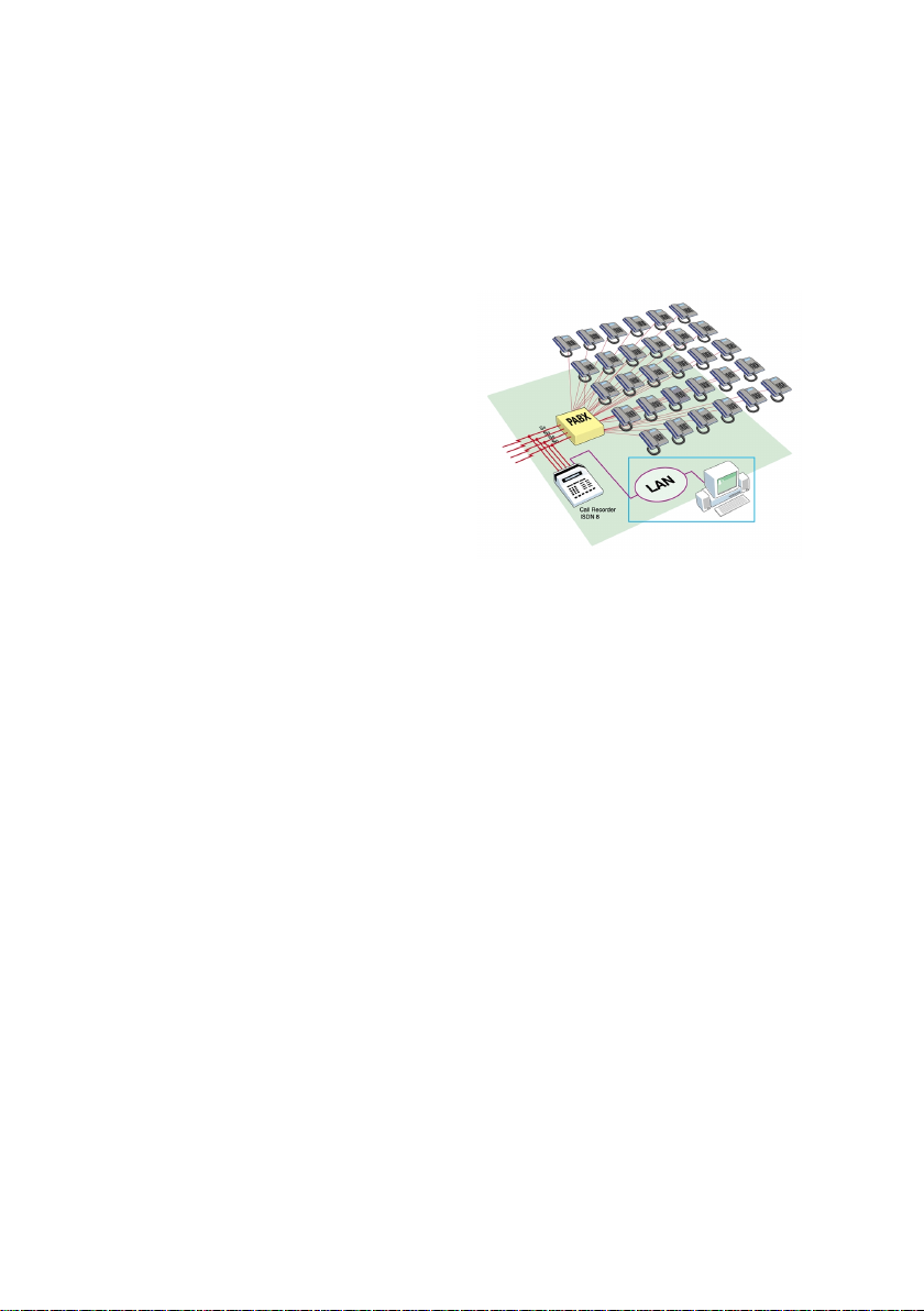
2. As an appliance between the
ISDN network-lines and the
telephone exchange, and which
records all external calls of a
firm. In this case one of the
bigger versions, ISDN2 or
ISDN4, would usually be more
appropriate. The advantage of
connected between the network lines and the
telephone exchange
this method of connecting is that
the calls of all the phones in a
company are recorded and that each individual one can be recognized.
1.2 Mixing, Compression and Capacity
A Call Recorder ISDN applies two methods to efficiently store the ISDN signal.
First the incoming and outgoing signals are mixed digitally, which results in a
digital recording of the same quality as the original signal. Every recording is then
compressed by a factor of 7.5. The resulting compressed recording is
theoretically of a lower quality, but any difference with the original is difficult to
hear.
Based on the experience gained with the thousands of Call Recorders already
delivered, it can safely be said that the standard compression applied to
telephone calls is fully satisfactory.
If the quality of the recordings is especially important, it is possible to set a lower
compression factor; the advantage is a significant gain in quality, the
8
Call Recorder ISDN Manual - ©2001 - Vidicode Datacommunicatie BV
Page 9

disadvantage a lower storage capacity. When only telephone conversations are
being recorded, little is gained because the quality of the telephoneline itself is a
limiting factor. Less compression, resulting in a higher quality, will make a
difference, however, when one is recording a meeting via a microphone.
High and low compression can be interchanged. It is sufficient to change the
setting prior to recording. The recorder will recognize the compression method
used when the recordings are being played
The maximum number of recordings that can be stored in the recorder having a
hard disk is 300,000 for all models, which means there are no practical
restrictions.
When the hard disk is approaching its full capacity, the recorder will give a
warning signal well in time for the user to check if there are any objections to the
oldest recordings being overwritten.
1.3 The network Interface and Compatibility
All Call Recorders ISDN (as well as the analog models you might come across)
have been provided with an Ethernet interface. The purpose of this interface is to
exchange recordings with computers and networks.
1.3.1 Network Protocol
The Call Recorder ISDN uses TCP/IP as network protocol. The recorder can be
seen as an FTP server with only a root directory. If necessary, a system manager
can alter the configuration of the Call Recorder via the Telnet protocol. It is
possible to exchange files both on local area networks and via wide area
networks and Internet. The network is used in combination with the optionally
available Call Recorder Archive software. This standard interface also makes it
possible for a third party to supply applications.
1.3.2 PC Compatibility
Call Recorder recordings can be played via the loudspeakers of a PC. If no
compression has been applied almost any PC with a sound card will be able to
play the recordings. After compression this is no longer possible and special
software is needed to play the files.
Call Recorder ISDN Manual - ©2001 - Vidicode Datacommunicatie BV
9
Page 10

The optionally available Call Recorder Archive Software makes it possible to play
direct from standard compression (CRF file format) and is also able to export
these recordings without loss of quality to the relatively efficient format ADPCM
(.WAV) which can be played on every PC. If compressed files are sent to a third
party, they can be listened to with the help of a freeware program provided
especially for this purpose by Vidicode. It can be found on our website
www.vidicode.nl
.
1.4 Security
The user can protect access to the recorder by means of a code. This will prevent
others from listening to recordings on the recorder. Access from the network has
also been secured by means of codes.
Security with codes is less safe than security with Crypto Cards, available as an
option. Crypto Cards also offer a watertight security if the Call Recorder is stolen,
or when recordings are sent via the Internet. Without the correct card and the
pincode that goes with it it is impossible to listen to the recordings.
10
Call Recorder ISDN Manual - ©2001 - Vidicode Datacommunicatie BV
Page 11

1.5 Some Terminology
For clarity the following terms are used to refer to the recorder’s controls:
1: LCD or display
2: Softkeys
The screen that gives the user information
The keys under the display that perform the
function on the display
3: Telephone keys
4: Function keys
The keys 0 and 1 to 9, * and #
The keys with their function shown above them as
a pictogram
Call Recorder ISDN Manual - ©2001 - Vidicode Datacommunicatie BV
11
Page 12
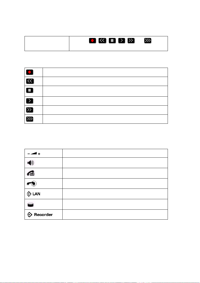
5: Recording keys
The keys
, , , , and , similar
to those on a cassette or video recorder
The following terms are used to describe the recording keys:
Record key
Rewind key
Stop key
Play key
Fast forward key
Special Call Recorder key for selecting the next recording
The following are the function keys:
12
Call Recorder ISDN Manual - ©2001 - Vidicode Datacommunicatie BV
Volume control keys
Loudspeaker key
Call Recorder key
Monitor key
Menu (Configuration) key for network configuration
Disk key
Menu (Configuration) key for recorder configuration
Page 13
2 Installing the Call Recorder
2.1 Unpacking
The Call Recorder comes supplied with the following parts:
• mains supply adapter
• 1 ISDN cable of 240cm per S0 bus
• 1 ISDN cable of 60cm per S0 bus
• 1 T-connecting piece for ISDN cables per S0 bus
• this manual
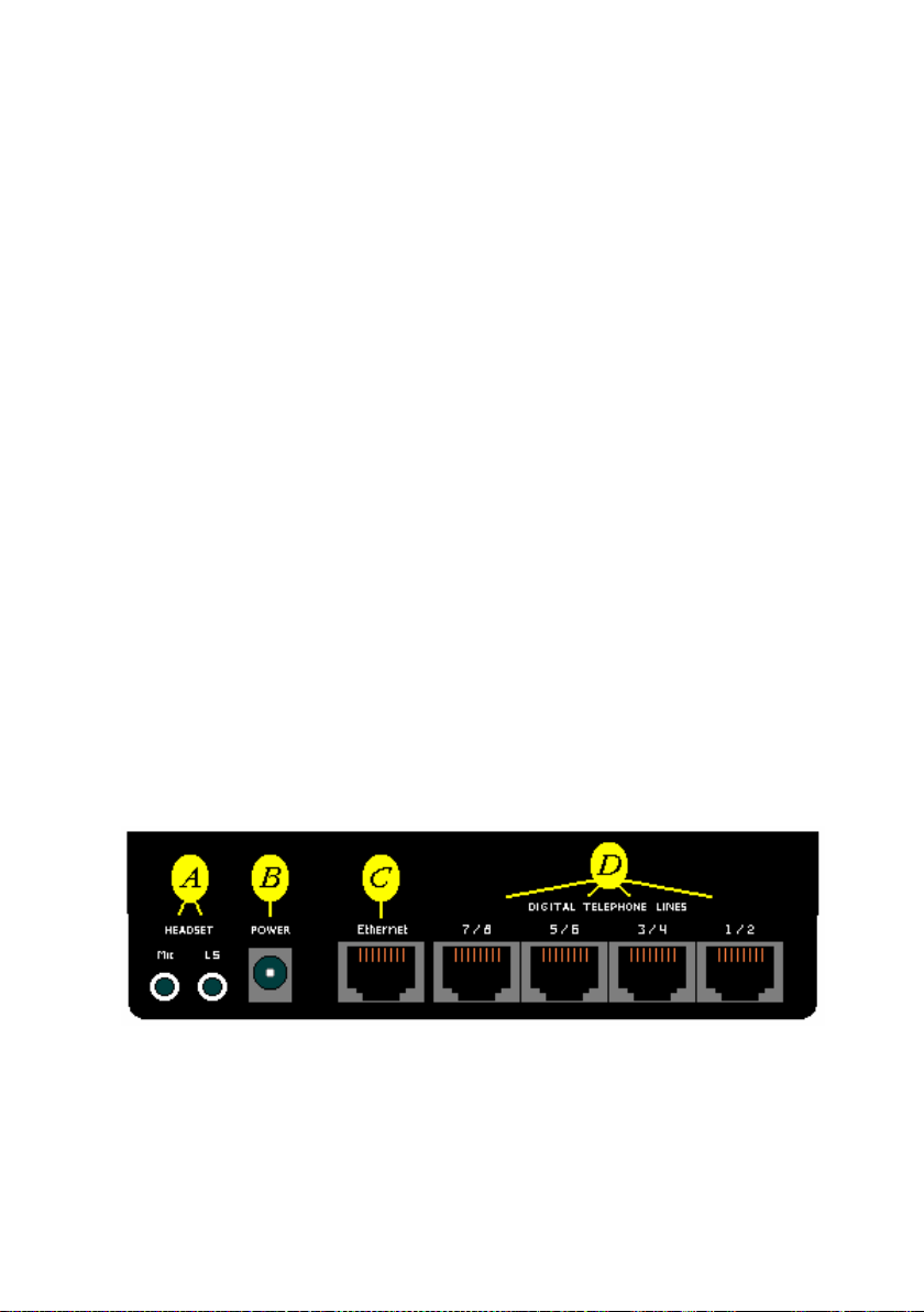
2.2 Connecting the Call Recorder
The way the Call Recorder is connected depends on the intended use. The
connections available are listed below.
A Connection for headset/microphone/external speakers (not
compulsory)
B Connection for external mains supply
E Connection to a 10BaseT Ethernet hub/switch (not compulsory)
D 1 to 4 S0 buses of ISDN basic connections
Call Recorder ISDN Manual - ©2001 - Vidicode Datacommunicatie BV
13
Page 14

2.2.1 Connecting the power supply
This is done as follows:
B Connect the external mains supply adapter to B
The recorder has been designed to be permanently connected and there is no
on/off switch. It comes with an internal battery which is provided only to serve the
power supply to the internal clock.
2.2.2 Connecting the S0 buses
The ISDN S0 bus allows for several machines to be connected in parallel. They
are connected as follows:
D Connect the S0 buses to the ports marked Digital Telephone Lines 1-2,
3-4, 5-6, and 7-8.
Disconnect the connection between a wall socket and the ISDN phone or switch.
Reconnect again with one of the cables supplied and the T-piece. Connect the
recorder with the other cable supplied. It does not matter in which place the
recorder is connected or where the short or the long cable is used. The cables
can be used in the way most suitable to your situation. Connect to the recorder as
follows:
- With a recorder ISDN1, connect to the 1-2 port
- With a recorder ISDN2, connect to the 1-2 and/or the 3-4 ports
- With a recorder ISDN4, all ports can be used
2.2.3 Connecting external loudspeakers (not compulsory)
The LS port can take various components having an audio input. Some common
components are:
- Amplified loudspeakers such as those used for PCs
- Headsets, such as those used for PCs
- Another recorder, if a recording needs to be transferred onto tape
14
Call Recorder ISDN Manual - ©2001 - Vidicode Datacommunicatie BV
Page 15

If loudspeakers are connected, they tend to be the loudspeakers that PCs come
equipped with. Such a set will have a stereo connection, and as the signal coming
from the Call Recorder is mono, the sound will come from only one speaker. This
can be solved by connecting the loudspeakers in parallel. The optionally available
loudspeaker set art. 1197 is already connected this way.
A Connect audio apparatus to the ‘LS’ port
2.2.4 Connecting the microphone (not compulsory)
The Call Recorder may be used as a dictating system or recorder of meetings. An
external microphone can be connected for this purpose. A headset is commonly
used both for recording and reproducing. The optional article 1196 available from
Vidicode is a conference microphone suitable for small meetings.. Your supplier
will be able to advise you about a microphone system suitable for bigger meetings
which can be used in combination with the Call Recorder.
A Connect a microphone to the ‘Mic’ port
2.2.5 Connecting to the LAN (not compulsory)
If you possess PC software for the Call Recorder the following connection is
possible:
C Connect the Ethernet port of the recorder with a hub or switch of
your network using a standard network patch cable
This is the preferred way for an office environment.
The port to be connected to needs to support 10-BASE-T (10 Megabit), which is
almost always the case, as most modern network ports automatically switch
between 10 Megabit and 100 Megabit. It is better to connect to a switch above a
hub.
For a direct connection between the Ethernet port of the recorder and the
Ethernet port of a PC
E Connect the Ethernet port of the recorder with the Ethernet port of
the PC using a special crossover cable
Call Recorder ISDN Manual - ©2001 - Vidicode Datacommunicatie BV
15
Page 16

In this way a very fast connection between a PC and a recorder can be
established for applications where there is only one PC and one recorder. When
such a fast connection is required but the PC has no Ethernet card but instead
has a USB port, as is common on notebook PC’s, a USB to Ethernet adapter can
bridge the gap and offer a cost efficient high speed connection.
The cable for this connection is not supplied, as such cables can vary widely in
length and configuration. Most system managers will have a supply of them in
stock.
2.3 Turning on the power
Connect the mains supply adapter to the mains. The display will show the
following text:
RESET
Followed by:
INIT
Ending with for instance:
Monday 19-08-01 10:53
Call Recorder
Sometimes the following message is displayed:
Monday 01-01-00 00:00
***The clock is Wrong***
16
Call Recorder ISDN Manual - ©2001 - Vidicode Datacommunicatie BV
Page 17

This means that the clock has not been configured yet, and should first be set to
the right date and time. How to do this is explained in the next chapter, which
covers configuring the Call Recorder.
Call Recorder ISDN Manual - ©2001 - Vidicode Datacommunicatie BV
17
Page 18

18
Call Recorder ISDN Manual - ©2001 - Vidicode Datacommunicatie BV
Page 19

3 Configuring the Call Recorder
A newly installed recorder will record all telephone calls of the S0 buses to which
it is connected without any further adjustment. With the help of a number of
installation questions, however, it is possible to adjust the recorder even closer to
the wishes of the user.
The installation menu can be reached by pressing the configuration key
Access to the recorder may have been secured with a password. At delivery this
is not yet the case.
When installing, you will find the options represented by the softkeys indicated on
the display. You can scroll through the options with the recorder keys.
selects the previous menu function
selects the next menu function (similar to ‘NEXT’)
3.1 Loudspeaker
This determines whether the internal loudspeaker is used when playing or
listening in to the recordings. If it is not used, an external loudspeaker should be
connected.
The display shows:
Speaker: On
NEXT CHANGE STOP
The internal loudspeaker is switched On or Off with the CHANGE softkey.
Call Recorder ISDN Manual - ©2001 - Vidicode Datacommunicatie BV
19
Page 20

3.2 Playback Volume
Volume: 10
NEXT CHANGE STOP
This option sets the preferred playback volume either of the internal loudspeaker
or of the loudspeaker connected to the loudspeaker port (LS).
By repeatedly pressing the CHANGE key the volume that is set when playing
starts can be adjusted from the value 0 to 15. When playing the recording the
volume can be temporarily adjusted even further with the volume keys. The
volume settings will be stored but the temporary adjustments will not.
3.3 Speech Compression
The display shows:
Compress Speech: Yes
NEXT CHANGE STOP
Thanks to speech compression the recorder can store a great number of hours of
speech. The compression applied is a factor 7,5 compared to standard ISDN,
after the incoming and outgoing signals have first been mixed. Quality loss as a
result of compression is minimal, and you are strongly advised not to switch off
compression. There is no objection to temporarily switching off compression if you
want to assess the difference in quality for yourself. In that case new recordings
will not be compressed. After you have switched on compression again, however,
all recordings not yet compressed will be compressed. Microphone recordings will
not be compressed. Compression does not work in combination with the Crypto
Card option.
3.4 Use of the CryptoCard
The display shows:
20
Call Recorder ISDN Manual - ©2001 - Vidicode Datacommunicatie BV
Page 21

Use CryptoCard: No
NEXT CHANGE STOP
The use of the Crypto Card option is discussed in Chapter 6. For now it is
sufficient to say that the Crypto Card cannot be used in combination with
compression. The CHANGE option is therefore not available when compression is
switched on.
3.5 The Clock
Clock: Mo 29-03-01 16:48
NEXT CHANGE STOP
To set the clock select ‘CHANGE’. The day is set with the telephone keys:
Sunday is 1, Monday 2, etc. The telephone keys are also used to edit date and
time. The
be changed. Then select ‘STORE’ to confirm, or ‘CANCEL’ to undo the editing.
Clock: Mo 29-03-01 16:48
STORE CANCEL
and keys are used to place the cursor in the position that is to
3.6 Setting the Password
Password Active: No
NEXT CHANGE STOP
When CHANGE is selected the same password should be entered twice.
Hereafter the password is active. The password is any number you choose with a
maximum length of 8 numbers in total.
The password safeguards the access to playing and all settings.
Call Recorder ISDN Manual - ©2001 - Vidicode Datacommunicatie BV
21
Page 22

If the wrong password is entered 3 times, the access to the recorder is blocked for
15 minutes, although recording will still be taking place.
Note: Never activate the password if you are uncertain whether you can
remember it. The recorder has been very well safeguarded, and if you forget the
password you will have a big problem. The password is not active at delivery, and
has been set at 0000.
Note: The password does not offer total protection. In theory it could be broken. If
extreme safety measures are needed one should use a Crypto Card.
3.7 Selecting the Language
Language: English
CHANGE STOP
A selection of languages has been installed. Once you have selected an option
here configuration is complete.
3.8 Other Configurations
The Call Recorder has several service menus with more configurations. The use
of these should be left to qualified personnel who have studied the service
manual. If so desired, access to the service menus can be blocked by an
additional service password.
22
Call Recorder ISDN Manual - ©2001 - Vidicode Datacommunicatie BV
Page 23

4 Operating the Recorder
This chapter covers the operation of the recorder and additional options for
configuring it.
4.1 Recording Telephone Calls
The Call Recorder has been designed to record automatically and cannot be
influenced by the user. This can be tested by starting a telephone call. The
display will show which line is used, and whether it is an incoming or outgoing
connection. You might see, for instance:
Friday 07-12-01 15:31
The display in this example shows that there is an incoming call on line 3, and an
outgoing one on line 8. If the connection is a speech connection the call will be
recorded automatically.
In the case of a data connection, for example a connection from a PC to the
Internet, the display will show that the line is active, but no recording will be made.
It will also show that a line is reserved when the handset has been taken off the
hook, but as long as there is no connection no recording will take place.
Via service menus it is possible to set the recorder in such a way that failed
connections and data connections are also registered, albeit without recording in
the case of a data connection. This will only be of interest in special applications,
however. In order to keep the content of the recorder clear, the basic
configuration has been set not to register failed connections and data
connections.
3< 8>
4.2 Recording with the microphone
The Call Recorder can be used as an audio-recorder at any time, with the same
high capacity it has when recording telephone calls. Provided a microphone has
Call Recorder ISDN Manual - ©2001 - Vidicode Datacommunicatie BV
23
Page 24

been connected, the Call Recorder is ready for recording at any time. It does not
matter if telephone calls are being recorded as well.
Experience has shown that the Call Recorder is mainly used as an audio-recorder
in meetings, to facilitate note taking.
Automatic Volume Control and the Microphone
An important feature of the Call Recorder is that it will automatically adjust itself to
a weak signal level. This is asking a lot of the Call Recorder, because sometimes
the microphone has to cope with a voice speaking right into it, whereas when it is
recording meetings people may be quite a long distance away. Although the
automatic volume control of the Call Recorder is extremely good, it is advisable to
purchase a separate table microphone if the recorder is often used for meetings.
The quality of recordings via the headset microphone is more than adequate for
occasional use. In order to record bigger meetings a special microphone system
is required that can be connected to the microphone port.
4.2.1 Recording
Recording is started by simultaneously pressing the Record and Play keys. (
and
). The display will show:
Recording Microphone!
19-08-01 10:59 00:00:53
The time counter can be seen to move during recording.
Recording is paused by pressing the Play key. When the Play key is pressed
again, recording will continue, while the Stop key stops recording. Next, you can
indicate whether you want to STORE the recording or DELETE it, by pressing the
appropriate softkeys. The recorder will give you 60 seconds to decide this in; if
you do not, the recording will automatically be stored.
Code: __________________
STORE 55 DELETE
24
Call Recorder ISDN Manual - ©2001 - Vidicode Datacommunicatie BV
Page 25

If the Play key is pressed in this situation, the recording can first be listened to,
and deleted or stored later.
It is also possible to type in a code that can later facilitate searching for the
recording. This code may contain both numeric and alphanumeric symbols . The
alphanumeric symbols are indicated above the number keys.
4.3 Searching for and Playing of Telephone Calls
A Call Recorder will first have to search for a recording before playing it.
A remarkable property of the Call Recorder is that it can play a recording while
simultaneously recording up to 8 telephone calls. When it is playing you do not
have to worry about the recording of telephone calls. When you are recording
from a microphone the situation is different. It is not possible to record from a
microphone and play a recording at the same time.
There are various search criteria, and they can be used in a combined search
request, e.g. all calls in March 2002 with telephone number 0123456789.
4.3.1 Searching for (Telephone) Recordings
When
is pressed the following text is displayed:
Playback Calls
SEARCH LAST STOP
To listen to the latest recording press the ‘ LAST’ softkey. The recording will be
played straight away.
If the ‘SEARCH’ softkey is pressed the display will say:
Calls from 31-03-01
SEARCH LOCAL STOP
The Date Search Key
Call Recorder ISDN Manual - ©2001 - Vidicode Datacommunicatie BV
25
Page 26

The date can now be changed, either by filling in the exact day, or by typing in a *
for day, date and year. The following selection, for example, gives you all the
telephone calls from March 2001:
Calls from **-03-01
SEARCH LOCAL STOP
It is possible to press the ‘SEARCH’ softkey straightaway, or to fill in other search
criteria, enabling you to continue to the key ‘LOCAL’.
The LOCAL Search Key
Do remember when searching that the other search criteria are enabled as well,
so if you want a search of all the calls by a certain local number the date should
be filled entirely by wildcards, as shown below:
Calls from **-**-**
SEARCH LOCAL STOP
The ‘LOCAL’ search key refers to the MSN number of the person within your
house or organisation who has called, as communicated by your own house
exchange or telephone installation to the public network. It is therefore possible to
recognize each telephone within a company, so long as it has been programmed
in the exchange, which is almost always possible.
The ‘LOCAL’ search key is therefore used to get a picture of all calls by a specific
phone or group of phones within your company.
Note: These data are recorded from the line. In practice one is not always certain
whether the area code is represented on the line. We advise you to search for
your own number with wildcards in the following way: * (number). The number 179
3617400 would be entered as follows: *3617400.
The REMOTE Search Key
REMOTE refers to the number selected by the caller. This number is only
available with outgoing calls.
26
Call Recorder ISDN Manual - ©2001 - Vidicode Datacommunicatie BV
Page 27

The ‘REMOTE’ search key can be used to get a picture of all calls in which a
certain number was selected. It might be interesting to do this for all calls in which
part of a number, e.g. the country code, was selected. For Germany one would
key in 0049*, for instance.
The CONNECT Search Key
‘CONNECT’ refers to the MSN number of the phone the caller is connected to.
In an outgoing call this need not be the number that was dialled. This sounds
strange, but as a rule you dial a main number, whereas the phone that answers
may have its own number which you can be connected to directly as well.
In an incoming call ‘CONNECT’ refers to the number that initiated the call.
The ‘CONNECT’ search key is used when searching for calls with a specific
person or company. In order to search for a specific caller the complete number is
entered. This search key can often (but not always) be used to search for calls
with a particular company, as MSN numbers tend to differ only in the last digits.
You could for instance search on 079 5124*. There is no guarantee, however, that
all numbers of a company form such a connecting group.
The LINE Search Key
Each S0 bus has 2 lines available, and depending on the way in which your
telephone exchange has been set up, the line number (1 to 8) may offer useful
additional information. The line numbers correspond to the numbers on the backpanel of the recorder.
The Search Command
After the relevant search criteria have been entered, the ‘SEARCH’ softkey is
pressed, and the Call Recorder will compose the selection.
Important: It is not necessary to use the search criteria. It is a standard feature of
the recorder to enter the date of today, and ‘wildcards’ for all other search criteria.
This does imply that if you are searching for all the recordings of a number
dialled, for instance, the date itself should be filled in as a wildcard.
The first recording of the selection made will be displayed, as well as the total
number of recordings found.
Call Recorder ISDN Manual - ©2001 - Vidicode Datacommunicatie BV
27
Page 28
31-03-01 08:53 1/416
SEARCH INFO STOP
The and keys allow you to scroll backwards and forwards in time through
the selection made, until you have found the recording you want.
When ‘INFO’ is pressed, information about the connection will be displayed, e.g.
for an outgoing call from 3617400 to 0795423861 the screen will show:
3617400 > 795423861
BACK
or for an incoming call from 0795423861 to our number 3617400:
793617400 < 795423861
BACK
4.3.2 Playing the recording
The recording can be played with the
key.
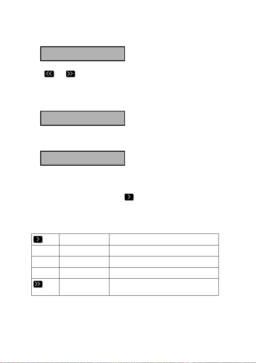
4.3.3 The Function of the Recorder Keys Before and During Playback
The uses of the recorder keys before and during playing back recordings are:
Before playback Starts playing the selected recording
During playback Pauses playback
During pause Resumes playback
Before playback Selects the next recording in the selection
of recordings
28
Call Recorder ISDN Manual - ©2001 - Vidicode Datacommunicatie BV
Page 29
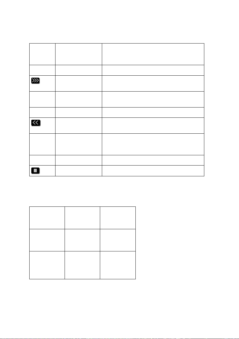
During playback Fast forwarding. This is done with
increasing speed so that the right place is
rapidly found even in long recordings
During playback Starts playing the next recording in the
During playback Fast rewinding. This is done with increasing
The uses of the telephone keys whilst playing back the recordings are:
1
10 seconds
back
4
60 seconds
back
Before playback Starts playing the recordings one after the
Before playback Selects the previous recording in the
During playback Stops playback
2
next
message
5
pause
other
selection
selection
speed, so that the right place is rapidly
found even in long recordings
3
10 seconds
forward
6
60 seconds
forward
7
300
seconds
back
Call Recorder ISDN Manual - ©2001 - Vidicode Datacommunicatie BV
89
300
seconds
forward
29
Page 30
*
30 minutes
back
0
stop
#
30 minutes
forward
4.4 Searching for and playing microphone recordings
As with playing call recordings, playing microphone recordings always starts with
searching for the recording.
Microphone recordings can also be played while telephone recordings are being
made.
There are only two search criteria for microphone recordings, date and code.
4.4.1 Searching for microphone recordings
Press the
display might show:
Playback Mic.records
SEARCH LAST STOP
Searching is different from searching for call recordings because there are fewer
search criteria.
To listen to the latest recording press the ‘LAST’ softkey. The most recent
microphone recording will be played.
If the ‘SEARCH’ softkey is pressed, the display will show:
Mic.recs from 31-03-01
SEARCH CODE STOP
The DATE Search Key
30
Call Recorder ISDN Manual - ©2001 - Vidicode Datacommunicatie BV
key to indicate you want to play microphone recordings. The
Page 31
The date can now be changed, either by filling in the exact day, or by typing in a *
for day, date and year. The following selection will give you all the microphone
recordings from March 2001.
Mic.recs from **-03-01
SEARCH CODE STOP
Now either press the ‘SEARCH’ softkey straightaway, or fill in further search
criteria, with the possibility of continuing to the CODE key.
The CODE Search Key
The CODE search key is unique to microphone recordings. Earlier on, in 4.2 you
have seen that it is possible to type in a code, when stopping a recording.
The first recording of the selection made will be displayed, as will the total number
of recordings found.
20-06-01 11:26 1/25
SEARCH CODE STOP
The and keys allow you to scroll backwards and forwards in time
through the selection made, until you have found the recording you want.
The recordings can be played with the
key.
The user can change the CODE search key at a later moment. In this respect
‘CODE’ differs from the other search criteria.
4.4.2 Playing the microphone recordings
See the instructions in 4.3.2 about playing call recordings, as the procedure is
exactly the same.
Call Recorder ISDN Manual - ©2001 - Vidicode Datacommunicatie BV
31
Page 32

4.5 The DISK key
The Call Recorder is meant for continuous automatic recording. The hard disk will
be written to until it is full, at which point the oldest recordings will be
automatically overwritten. If compression has been switched on, this will perhaps
only be after several years of continuous usage. Of course this depends on the
number of calls and the capacity of the hard disk.
The disk function key
can be used to retrieve information about the contents
of the hard disk in the recorder.
Free: 1032(7772) Hours
NEXT STOP
Two numbers are displayed, i.e. the space without compression and the space
with compression.
The next display is of special importance if the disk is ever full up.
Oldest record.: 01-11-00
NEXT STOP
As has been said before, when the disk is full, the oldest recordings are
automatically erased. This information enables you to determine whether that is a
problem.
The third function informs the user of the total number of recordings on the hard
disk. This is the total of recordings from both sources: telephone lines and
microphone.
Total recordings: 14325
STOP
32
Call Recorder ISDN Manual - ©2001 - Vidicode Datacommunicatie BV
Page 33

4.6 The Monitor
De monitor makes it possible to listen in to conversations via the recorder. While
the recorder is in use, the display will indicate which lines are engaged, e.g.:
Monday 10-12-01 14:01
1> 2< 5< 7<
If you wanted to listen in to the incoming call on line 2, you would press the
Monitor key (
The display will show:
(press 1-8) STOP
Now press the number 2. From then on you can listen in to the call on line 2. You
stop the listening in by pressing the ‘STOP’ key (
Once activated, the monitor function stays active with every other call on the
same line. Therefore the monitor always needs to be switched off manually.
).
Line Monitor
).
Call Recorder ISDN Manual - ©2001 - Vidicode Datacommunicatie BV
33
Page 34

34
Call Recorder ISDN Manual - ©2001 - Vidicode Datacommunicatie BV
Page 35

5 The Network Interface
Every Call Recorder has been provided with a 10BaseT Ethernet interface. This
type of interface is the most common one for local area networks and connection
to the Internet.
The protocol chosen for communication via the Network is TCP/IP, the Internet
protocol that can be used on most local area networks.
5.1 The possibilities
The main reason for developing the network interface is to offer the possibility to
centrally archive the recordings, or to make a back-up copy of the recordings. The
optionally available Call Recorder Archive Software can be used for archiving a
maximum of 4 recorders.
The biggest advantage of the network interface is the high transfer speed of big
audio files, another is that they can be retrieved both via the internal network and
via the Internet. There are other possibilities, however, and these are listed below:
- Archiving by own applications with the help of FTP. The recorder works as a
normal FTP server.
- Audio monitor function; recordings can be listened to remotely via the
loudspeakers of a PC
- Remote configuration by system managers
There are various ways in which the connection can be made, so that it is almost
always possible to archive or listen remotely. The various possibilities are
discussed below, from very simple to very elaborate.
• Connecting one PC with one recorder is possible by supplying the PC with a
networkcard and connecting the PC via a special (crossed) cable. An even
simpler way is to use a USB to Ethernet adapter, available as a cable. They
produce a very fast connection between the PC and the recorder.
• Connecting a PC with various recorders in the same building is possible by
connecting all recorders and the PC onto the local network.
Call Recorder ISDN Manual - ©2001 - Vidicode Datacommunicatie BV
35
Page 36

• A good example of a simple solution to get access to a number of recorders
at a distant location is to work with an ISDN router with hub, as provided by
several manufacturers such as Cisco or Intel. The recorders are connected to
a hub, and a PC with our archive software is connected to the hub via its
ISDN software.
• In a large scale application, PC’s and recorders are connected via the
internet or an intranet.
5.2 Configuration
Configuring the network function of a Call Recorder for local use is not especially
difficult, although within a company environment it is advisable for the network
manager to enable the network function of the recorder. He or she is the person
best suited to judge how the recorder should be configured to function properly
with the other systems on the network.
The remote use of the recorder via the Internet or an intranet is less simple. The
system manager should allow for the interaction between the recorders and the
router/gateway/firewall combination that connect the local network and the wide
area network.
Press the
key to configure the network. Please keep in mind that it is not
possible to configure the network whilst recording. The key will not react in that
case. For network configuration the following settings are available:
Network active: Yes
NEXT CHANGE BACK
If you do not use the network, the answer here should be “No”. The next question
concerns FTP, which can be used for archiving, for example.
FTP active: Yes
NEXT CHANGE BACK
36
Call Recorder ISDN Manual - ©2001 - Vidicode Datacommunicatie BV
Page 37

When FTP is not used the answer to this question should again be “No”. If it is
used, there are two follow-up questions:
FTP ID: 0000
NEXT CHANGE BACK
This is the ID a user should give to approach a Call Recorder via FTP. There is
only one possible ID.
FTP code: XXXXXXXX
NEXT CHANGE BACK
This is the password for a FTP session. The default is 0000.
FTP Server Port: 21
NEXT CHANGE BACK
Access via the Internet on a network with several FTP servers, e.g. several Call
Recorders, can pose problems for the router if the IP port for all FTP servers is
the same. If that is the case, it may be necessary to set a number as an
alternative to the common value of 21. In all other applications the default value of
21 should be maintained. If a different value is set the system manager should
take care that there is no conflict.
The next question concerns a property of your network:
Use DHCP Server Yes
NEXT CHANGE BACK
If there is a DHCP, server, the recorder will automatically be assigned an IP
address (network address), in which case any application called up by the
recorder will ask for the IP name of the recorder. If DHCP is not available the user
will have to give an IP address himself, which will be used by any application
approaching the recorder:
Call Recorder ISDN Manual - ©2001 - Vidicode Datacommunicatie BV
37
Page 38

IP addr: 168.102.000.012
NEXT CHANGE BACK
If DHCP is available, there is no opportunity to change the IP address manually:
IP adrs: 168.102.000.012
NEXT BACK
In an application with linked networks without DHCP server there will not only be
a question about the IP address, but also about the IP subnet mask:
IP mask: 255.255.255.0
NEXT CHANGE BACK
The IP subnet mask is only applicable for access to recorders via the Internet or
intranet. Normally you will not have to change this setting.
If there is an IP subnet mask, there will be a gateway to the other network as well,
and the address of this gateway will be filled in. This should also be done if there
is a DHCP server.
Gateway: 0.0.0.0
NEXT CHANGE BACK
If the gateway is not applicable in your situation, you do not change anything.
If DHCP is used, the address mentioned here has come from the DHCP server
and the name found in the next question will be used :
IP name: CRPeter
NEXT CHANGE BACK
With most networks with a DHCP server it is possible to call the IP name of the
recorder, rather than the IP address. In that case it might be worthwhile to change
38
Call Recorder ISDN Manual - ©2001 - Vidicode Datacommunicatie BV
Page 39

the IP name into an easily remembered name such as CR-Peter. You should
always do so if it is possible to call the recorder with the IP name. Only if it is not
possible to call the recorder with its IP name, even though a DHCP server is
being used, should the IP address used to approach the computer be read from
the display of the recorder.
The next question concerns the use of the monitor function (Listening in via the
network).
Monitor active: Yes
NEXT CHANGE BACK
If the monitor is active, it allows you to set the accesscode for the monitor
function.
Monitor code: XXXXXXXX
NEXT CHANGE BACK
5.3 Use of the network interface
5.3.1 The FTP protocol
FTP is the standard method to ask for files via the Internet, which explains why
there is a lot of software that can retrieve the files of your Call Recorder. This
possibility is mainly of interest to developers, however.
Our Call Recorder Archive Software will be of more interest to the Call Recorder
user. In order to be able to use the archive software, the network functions and
FTP should be enabled. Depending on whether there is a DHCP server present in
the network, the IP address or the IP name should be given as well. When both
the PC with the software and the Call Recorders are connected to the net, all
recordings can be archived at a very high speed via the LAN.
The use of Call Recorder Archive Software and the installation of it on the PC are
explained in the helpfile that comes with the software.
Call Recorder ISDN Manual - ©2001 - Vidicode Datacommunicatie BV
39
Page 40

5.3.2 The monitor
The monitor protocol of the Call Recorder is not standard. For this reason the
monitor is of special importance for users of the Call Recorder Monitor Software
option.
To use Call Recorder Monitor Software the network needs to have been enabled
and the IP address or IP name given. The monitor function should also be
operating. The PC with the software will then be able to select from the recorders
present and to listen in to the conversations via the loudspeakers or headset.
The use of Call Recorder Monitor Software and its installation are also explained
in the helpfile that comes with this software.
40
Call Recorder ISDN Manual - ©2001 - Vidicode Datacommunicatie BV
Page 41

6 The Crypto Card option
The Crypto Card is, along with the Archive Software, the most important option of
the Call Recorder. Every Call Recorder has been provided with an IC card reader.
If a set of Crypto Cards is purchased, the recorder will automatically be able to
work with them.
Crypto Cards restrict the use of the Call Recorder ISDN, because compression of
the coded files will not be possible.
6.1 How a Crypto Card works
The Crypto Card works as follows:
• All recordings that are made while the Crypto Card is inside the computer are
coded. These recordings can only be played if one possesses a card from
the original set.
• Recordings are uniquely recognizable by the card number.
• The card has been safeguarded against interfering with a pincode or, if this
has been lost, with the PUC (Personal Unlock Code) provided at delivery.
As we have already seen, it is possible to configure the recorder in such a way
that recording can only take place with the card.
The function of the card is as follows:
• To ensure users who keep their cards with them that their recordings cannot
be listened to without their approval.
• To make it safe to transport recordings via the network or the Internet,
because they cannot be listened to without a card from the original set.
• To protect against unauthorized listening in, if the monitor function is used,
so that it is safe to listen to a conversation via Internet.
This method of protection is similar to the protection of telebanking via Internet,
and the risk that this form of protection is broken is very low.
Call Recorder ISDN Manual - ©2001 - Vidicode Datacommunicatie BV
41
Page 42

6.2 Changing the Card Code
The card code (PIN code of the Crypto Card) is only used when playing
recordings made with the Crypto Card. Select the option “Changing the Card
Code” from the settings menu. The recorder will first ask for your present card
code:
Card code: XXXX
CONTINUE STOP
The new card code can now be entered:
New card code: XXXX
CONTINUE STOP
The code then has to be entered once more as a check:
Repeat code: XXXX
CONTINUE STOP
The display will then show:
New card code accepted
STOP
If the wrong code has been entered three times running, the recorder will
automatically ask for the PUC. That will start a similar procedure with which a new
card code can be entered.
The PUC code must be entered correctly. Entering an incorrect PUC code five
times running will lead to the card being made invalid.
42
Call Recorder ISDN Manual - ©2001 - Vidicode Datacommunicatie BV
Page 43

WARNING
If you lose the PUC and the card code it will not be possible to play the
recordings made with the card. Your manufacturer CANNOT help you with this,
and the recordings will be permanently lost. For this reason we strongly advise
you to keep the PUC and a copy of the card in a secure place, such as a safe.
6.3 Recording with the Crypto Card
The Crypto Card can only be used if it has been configured to do so at
installation (See 3.4). If use of the Crypto Card has been set at installation, no
recordings will be made unless the card had been inserted.
Simply insert the Crypto Card in the recorder to operate it. The display will show
straight away that the card has been inserted and a sound signal will be heard. All
recordings will now be coded.
6.4 Playing Recordings with the Crypto Card
In order to play a recording the usual procedure for selecting a recording applies.
When you want to play coded recordings, the recorder will ask for your card code:
Cardcode: XXXX
CONTINUE STOP
Enter the code and confirm with ‘CONTINUE’.
The code does not need to be entered continually; it will remain valid for the entire
session. The code only becomes invalid when the recorder has been left
untouched for 15 minutes, or when the card is removed.
Playing coded recordings CANNOT be done at the same time as recording from
the line. Before starting to play, the recorder will ask permission to stop recording:
Call Recorder ISDN Manual - ©2001 - Vidicode Datacommunicatie BV
43
Page 44

Stop Recording?
YES NO
Obviously it will not be possible to play coded recordings with a card from a
different set. The original Crypto Card will be needed not only when playing, but
also when erasing a recording or changing the code of a recording.
44
Call Recorder ISDN Manual - ©2001 - Vidicode Datacommunicatie BV
Page 45

7 Erasing Recordings
A Call Recorder has been set up in such a way that it is not necessary to erase
recordings. When the Call Recorder is about to run out of space, it will start
erasing recordings automatically. These will always be the oldest recording.
Automatic erasing only occurs after the total capacity of the hard disk has been
used up.
You may want to erase a recording yourself, because it contains confidential
information that you do not want to fall in the wrong hands. Or, on the other hand,
you may consider the possibility of erasing highly undesirable in your application.
In contrast to the analog desktop recorder for 1 line, the Call Recorder ISDN does
not have the option of erasing recordings in its basic configuration. In order to
enable erasing, a system parameter needs to be changed, which can be done by
either your supplier or the system manager. The person in question will have to
consult the Technical Reference Manual, and he may need to have access to the
system password of the Call Recorder. Once the option to erase has been
enabled, every recording can be erased thereafter.
One important difference between erasing a recording on the Call Recorder and
erasing a file on your PC, however, is that the Call Recorder will genuinely erase
the recording, so that it cannot be retrieved, whereas a recording erased by the
PC is very easily found, and will only disappear if the space it takes up happens
to be needed for something else. The disadvantage of erasing in the way the Call
Recorder does is that it takes time to make space on the disk; the advantage is
that you can be sure that the information has disappeared.
To erase a recording proceed as follows:
Look up the call the way you are used to. You now see, for example:
20-11-01 15:37 1/5
SEARCH INFO STOP
Press the ‘INFO’ softkey. The display will show:
0793617181>0708800900
ERASE BACK ERASE
Call Recorder ISDN Manual - ©2001 - Vidicode Datacommunicatie BV
45
Page 46

Press both ‘ERASE’ softkeys simultaneously. The display will now read, for
example:
0793617181>0708800900
One moment please
As has been mentioned before, this takes some time because the recording is
being erased.
46
Call Recorder ISDN Manual - ©2001 - Vidicode Datacommunicatie BV
Page 47

8 Maintenance
Experience with products similar to the Call Recorder has taught us that you can
expect it to have a long life. The electronic parts of the Call Recorder do not
require any maintenance, but the mechanical parts may suffer wear and tear.
8.1 Changing the Disk Drive
Please bear in mind that the life of a disk drive (hard disk or LS 120 disk) is
shorter than that of the recorder itself. For this reason we advise you to replace
the hard disk preventatively after four years of use. If, after an external
accident, such as dropping the recorder, the recorder does not seem to function
optimally any more, it is also better to replace the disk.
The life of a hard disk can be longer. If regular backups are made with the help of
the Call Recorder Archive Software it may be possible to change the hard disk
after 5 years.
When replacing a hard disk, the manufacturer can copy the old recordings onto
the new disk.
8.2 Changing the Battery
It is very important that the internal clock of the Call Recorder stays working,
because date and time are the most important search criteria. In the case of a
power cut the clock will keep running on the internal battery. This is a standard
CR2032 cell available at almost every electronic or photo shop. We advise you to
change this battery every 3 years.
This is done in the following way:
- Unplug the recorder
- Open the recorder by unscrewing six screws at the bottom.
- Put the keyboard diagonally next to the recorder so that the connecting cable
need not be disconnected.
Call Recorder ISDN Manual - ©2001 - Vidicode Datacommunicatie BV
47
Page 48

- Replace the battery
- Screw the recorder shut again
- Set the clock as described in chapter 3.5.
48
Call Recorder ISDN Manual - ©2001 - Vidicode Datacommunicatie BV
Page 49

9 Accessories
There are several accessories available for your Call Recorder:
Call Recorder Archive software for Microsoft Windows (versions
95/98/ME/XP/2000/NT4), order number 1352
The function of this software is to archive the recordings of your Call Recorders
on a PC. These recordings can be played directly from the archive via the
loudspeakers of the PC.
This software can be used with all model Call Recorders that possess a network
interface. It is therefore possible to build up a combined archive of recordings
made with Call Recorders ISDN and Call Recorders for analog lines.
The software approaches Call Recorders as FTP servers. This method of
connecting can be used in almost every type of network connection. For more
information see Chapter 5.
The most important functions of the software are:
- Retrieving the contents of 1 to 4 recorders and displaying them in a database
- Searching for recordings in an often very extensive database with the help of
queries (search commands)
- Transferring all recordings or a selection of them to the hard disk of the PC
- Playing via the loudspeakers of a PC
- Exporting to standard PC format for sending to a third party via e-mail or
another medium
- Making sub-archives for storage on CD or DVD with the help of a CD
recorder or DVD recorder
The Archive Software can also be used to automatically retrieve all recordings, so
that there is always a back up of them present in the recorders. The Archive
Software is an almost indispensable accessory of the Call Recorder ISDN.
Crypto Card option, order numbers 1350, 1356 and 1357
This option has been extensively described in chapter 6.
Crypto Cards can be supplied in three different ways:
Call Recorder ISDN Manual - ©2001 - Vidicode Datacommunicatie BV
49
Page 50

- Article 1350, set of 3 identical cards
- Article 1356, set of 6 identical cards
- Article 1357, set of 4 x 3 different normal cards and 3 master cards that can
be used to play the recordings of the other cards.
Article 1357 is meant to be used as security in combination with Call Recorder
Archive Software that can archive the recordings of four recorders in a PC via
LAN, Internet or intranet.
Monitor Software, order number 1354
Monitor Software makes it possible to listen in to the recordings of a Call
Recorder via a LAN or via Internet. The user can choose from a list of recorders.
Crypto Card reader for the PC, order number 1351
The Crypto Card reader is needed for playing recordings made with a Crypto
Card on a PC. It can be used both with Call Recorder Archive Software and with
Monitor Software.
Table top Microphone for Recording Meetings, order number 1196
When the Call Recorder is regularly used for recording meetings, some users
prefer a tabletop microphone to use of the headset microphone. Various common
models can be used. The microphone referred to here is one especially designed
for video conferencing, eminently suitable for recording group conferences.
Multimedia Loudspeakers, order number 1197
When the internal loudspeakers do not suffice, multi media loudspeakers with
built-in amplifiers can be connected to the LS-connector of the recorder.
50
Call Recorder ISDN Manual - ©2001 - Vidicode Datacommunicatie BV
Page 51

10 Guarantee Conditions
This chapter gives a general overview of the guarantee conditions. We can send
you a copy of the complete text on request.
Your Call Recorder has a 12-month factory guarantee. The guarantee is effective
for normal use only. We would like to emphasize that the guarantee is not valid
under exceptional environmental conditions, such as extreme temperatures or
humidity levels, nor in the unlikely event of a lightning strike. The guarantee is
also not valid if the machine has not been handled properly, for example when it
has been dropped, or bumped into. Hard disks are fragile.
In order to qualify for guarantee, you should contact your supplier, and show the
receipt. If your supplier cannot help you, you should contact the manufacturer.
The manufacturer reserves the right to determine the final date of the guarantee
period on the basis of the date of production. Costs of transport to and from the
supplier or the manufacturer are for the buyer’s account.
We would like to stress that the guarantee is for parts only, and does not cover
any costs resulting from the breakdown of the Call Recorder or its software.
Call Recorder ISDN Manual - ©2001 - Vidicode Datacommunicatie BV
51
Page 52

52
Call Recorder ISDN Manual - ©2001 - Vidicode Datacommunicatie BV
Page 53

11 Additional Information
Call Recorder ISDN have various extra features that have not been described in
this manual. Additional information about this is given in a technical information
bulletin meant for suppliers; users can order this, or download it from the Vidicode
Internet websites (WWW.VIDICODE.NL or WWW.VIDICODE.COM for USA)
Subjects discussed in this technical documentation are the very extensive further
configuration options, remote configuring, and how to put a new software version
in the recorder.
The further configuration options concern all aspects of operation, but in our
experience most people are interested in configurations related to user’s access
and special ways of recording.
The way in which the Call Recorder ISDN operates, can be modified by your
supplier and other experienced programmers to fit in with your specific wishes.
That is why it comes supplied with its own programming environment, Argus
BASIC. At the moment the manual of Argus BASIC for the latest version of the
Call Recorder (with IP connection and IC card) is not yet available, but it will be
published via the Internet in the near future.
Call Recorder ISDN Manual - ©2001 - Vidicode Datacommunicatie BV
53
Page 54

54
Call Recorder ISDN Manual - ©2001 - Vidicode Datacommunicatie BV
Page 55

12 Index
A
accessories, 49
Archive Software, 39
Archive software for Windows, 49
Automatic Recording, 23
C
capacity, 7
card code, 42
Changing the Battery, 47
Changing the Disk Drive, 47
Clock, 21
CODE Search Key, 31
Compression, 8; 20
Configuring, 19
CONNECT Search Key, 27
Crypto Card, 41
Crypto Card option, 49
Crypto Card reader PC, 50
Crypto Cards, 10
D
date, 26; 30
Date Search Key, 25
DATE Search Key, 30
DHCP, server, 37
DISK key, 32
E
Erasing Recordings, 45
external loudspeakers, 14
F
Fast forward key, 12
Free Capacity, 32
FTP, 36
Function keys, 11
function of the recorder keys, 28
G
Guarantee Conditions, 51
I
Installing, 13
IP address, 37
IP port, 37
IP subnet mask, 38
L
Language, 22
LINE Search Key, 27
LOCAL Search Key, 26
M
Maintenance, 47
maximum number of recordings, 9
meetings, 24
microphone, 24
microphone for recording meetings,
50
monitor, 39
Monitor, 33
Call Recorder ISDN Manual - ©2001 - Vidicode Datacommunicatie BV
55
Page 56

Monitor Software, 40; 50
N
Network Interface, 35
O
oldest recordings, 32
S
Search Command, 27
Search Key, 26
Searching and Playing, 25
Security, 10
Softkeys, 11
Start a microphone recording, 24
Stop key, 12
P
Password, 21
PC Compatibility, 9
PIN code, 42
Play key, 12
Playback Volume, 20
Playing the microphone recordings,
31
Playing the recording, 28
Powering on, 16
PUC code, 42
R
Record key, 12
recording keys, 12
REMOTE Search Key, 26
Rewind key, 12
T
table microphone, 24
technical information bulletin, 53
Telephone keys, 11
Telnet protocol, 35
total number of recordings, 32
U
Unpacking, 13
USB to Ethernet, 35
W
website, 53
56
Call Recorder ISDN Manual - ©2001 - Vidicode Datacommunicatie BV
 Loading...