

Page 1

1
Call Recorder Single II
Manual
V2.
V2.V2.
V2.2222
VC20
VC20VC20
VC2000002222
Page 2

Manual Call Recorder Single II © 2011-2014 Vidicode®
2
Page 3

Manual Call Recorder Single II © 2011-2014 Vidicode®
3
The
The The
The Call Recorder
Call Recorder Call Recorder
Call Recorder Single II
Single IISingle II
Single II
1. Menu-keys
2. Backlight Display
3. Function keys
4. Speaker
5. Alfa-Numerical keys
6. CryptoCard reader
7. SD inserted LED (red)
8. SD card Slot
9. Recorder keys
10. Speakerphone key
11. Volume adjustment
Page 4

Manual Call Recorder Single II © 2011-2014 Vidicode®
4
Connection
ConnectionConnection
Connection
1. Power
2. Ethernet/LAN
3. RS 232 Serial
4. Switch
5. Loudspeaker
6. Microphone
7. Handset
8. Handset
9. Phone line Out
10. Phone line In
Page 5

Manual Call Recorder Single II © 2011-2014 Vidicode®
5
Recorder
RecorderRecorder
Recorder----keys
keyskeys
keys
The recorder keys have specific functions in different situations although
the operation is always very similar. During recording and playback the
keys have the standard recorder key functions as explained below.
Record Backward Stop Pause/Play Forward Skip
The and keys can be used to scroll through numbers in the
telephone book or through a settings menu. If no recording or playback
is taking place these keys always have an Up/Down or Left/Right
function. The key will always exit the current operation.
Function
FunctionFunction
Function----keys
keyskeys
keys
Page 6

Manual Call Recorder Single II © 2011-2014 Vidicode®
6
Alfa
AlfaAlfa
Alfa----numerical functions
numerical functionsnumerical functions
numerical functions
Page 7
Manual Call Recorder Single II © 2011-2014 Vidicode®
7
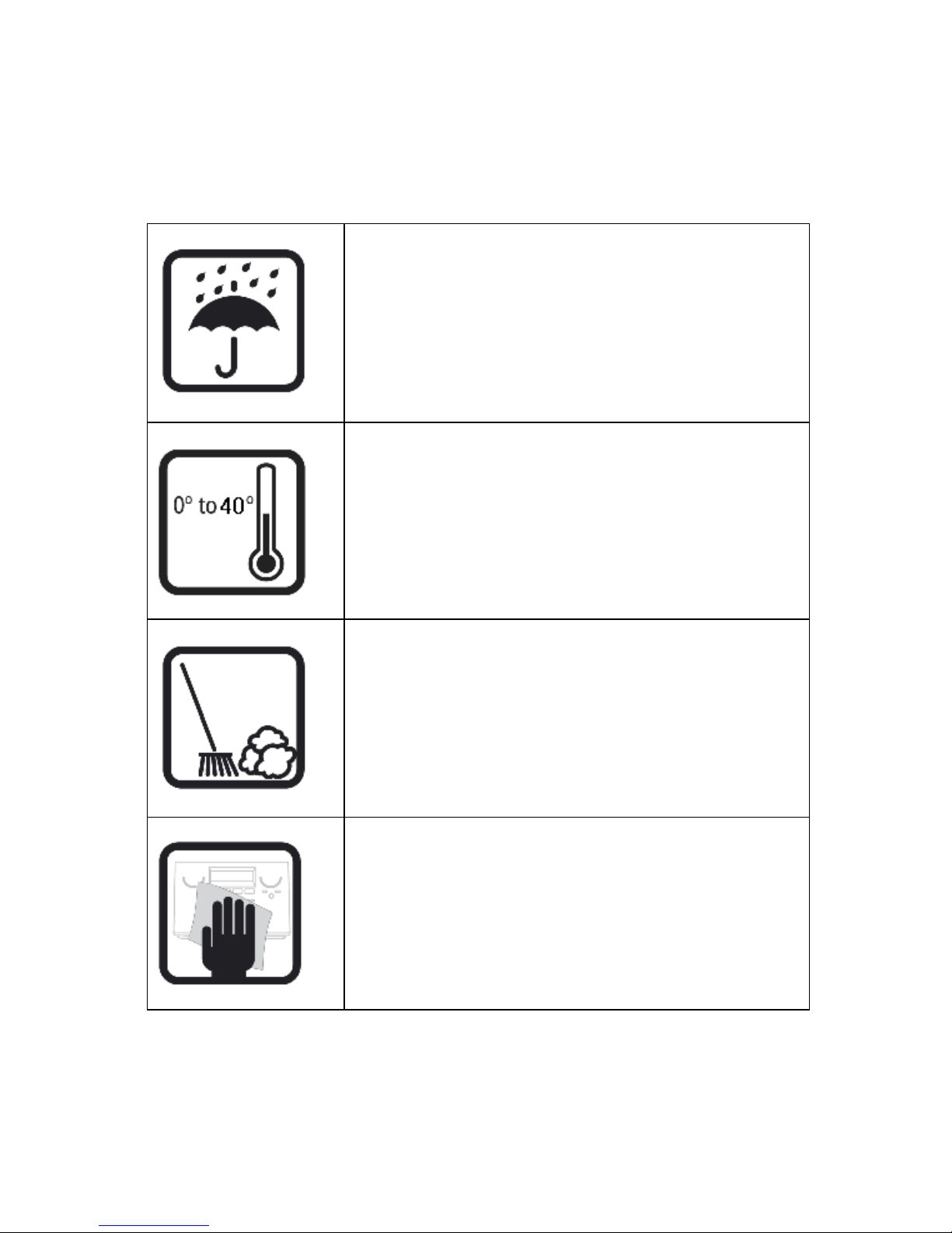
Care and Maintenance
Keep the Single II dry. If it gets wet, wipe it dry
immediately Liquids might contain minerals that
can corrode the electronic circuits.
Use and store the Single II only in normal
temperature environments. Temperature extremes
can shorten the life of electronic devices and
distort or melt plastic parts.
Keep the Single II away from excessive dust and
dirt that can cause premature wear of parts.
Do not use harsh chemicals, cleaning solvents or
strong detergents to clean the Single II.
Page 8

Manual Call Recorder Single II © 2011-2014 Vidicode®
8
Page 9

Manual Call Recorder Single II © 2011-2014 Vidicode®
9
Table of c
Table of cTable of c
Table of contents
ontentsontents
ontents
1 Operation and Important information .................13
1.1 Frequently used key indicators .............................13
1.2 Save Changes.........................................................14
1.3 Adjust the Volume ................................................14
2 Getting started .......................................................15
2.1 Out of the box.......................................................15
2.2 Connecting the power supply...............................16
2.3 Setting up the Single II for use .............................16
2.3.1
Set the clock.......................................................................... 16
2.3.2
Select the language.............................................................. 17
3 About the Call Recorder.........................................19
3.1 Automatic recording.............................................21
3.2 Notification ...........................................................21
3.3 Compression..........................................................22
3.4 Microphone mode.................................................22
3.5 Automatic Gain Control........................................22
4 Connecting to the recording source......................23
4.1 Record from an analogue telephone line ............23
4.1.1
Configure Record from Line ................................................ 24
4.2 Record from a digital telephone ..........................25
4.2.1
Configure Record from Handset.......................................... 25
4.2.2
Voice activated recording .................................................... 26
4.2.3
Set Start level, stop level and Silence Timeout ................... 26
4.3 Recording from the microphone ..........................27
5 Search and play recordings ....................................28
5.1 Search recordings..................................................29
5.2 Search according to date ......................................29
5.3 Search according to code......................................30
6 Copy recordings to SD card....................................31
6.1 Copy the last recording to SD card.......................31
6.2 Copy a selection of recordings..............................31
6.3 Copy an individual recording during playback ....32
Page 10

Manual Call Recorder Single II © 2011-2014 Vidicode®
10
7 Single II as Telephone.............................................33
7.1 Headset / Speakerphone .......................................33
7.2 Handset .................................................................34
7.3 Starting a call ........................................................34
7.4 Accept a call ..........................................................35
7.5 End a call ...............................................................35
8 Single II as Answering machine .............................36
8.1 Turn the answering machine On / Off..................36
8.2 Record a message..................................................37
8.3 New Messages. ......................................................38
8.4 Playback messages ................................................38
8.5 Remove messages..................................................39
8.6 System messages ...................................................40
9 The Telephone book ..............................................42
9.1 Add a contact........................................................42
9.2 Search a contact ....................................................42
9.3 Making a call from the telephone book ..............43
9.4 Edit a contact ........................................................43
9.5 Remove a contact..................................................44
9.6 Call History ............................................................44
10 Using the CryptoCard .............................................45
10.1 Insert CryptoCard into Single II.............................45
10.2 The CryptoCard and its PIN and PUC code ...........45
10.3 Making an encrypted recording ...........................46
10.4 Playing an encrypted recording............................46
11 The Network Interface ...........................................48
11.1 The Possibilities .....................................................48
11.2 Network configuration .........................................48
12 Settings ...................................................................49
12.1 Recording Source ..................................................49
12.2 Start method .........................................................50
12.3 Telephone settings................................................51
12.3.1
External handset ............................................................... 51
Page 11

Manual Call Recorder Single II © 2011-2014 Vidicode®
11
12.3.2
Flash time .......................................................................... 52
12.3.3
Wait after dial................................................................... 52
12.3.4
Caller ID............................................................................. 52
12.3.5
K-break detection ............................................................. 53
12.3.6
Rings to answer on ........................................................... 53
12.3.7
Rings always answer ......................................................... 53
12.3.8
Ring Volume...................................................................... 54
12.3.9
Ring frequency.................................................................. 54
12.3.10 Ring variation.................................................................... 54
12.3.11 Speaker after answer........................................................ 55
12.3.12 Maximum message time................................................... 55
12.4 Recorder Settings ..................................................56
12.4.1
CryptoCard ........................................................................ 56
12.4.2
Automatic SD Copy........................................................... 57
12.4.3
Notification ....................................................................... 57
12.4.4
Ask Store/Delete ............................................................... 58
12.4.5
Beep after store ................................................................ 58
12.4.6
Minimum call time............................................................ 59
12.4.7
Signal settings ................................................................... 59
12.4.8
Start Period ....................................................................... 61
12.4.9
Silence period.................................................................... 61
12.4.10 Compression...................................................................... 61
12.4.11 Microphone mode ............................................................ 62
12.4.12 Microphone amplification................................................ 62
12.4.13 Automatic Gain Control ................................................... 62
12.4.14 Footswitch ......................................................................... 62
12.5 Network settings...................................................63
12.5.1
Network active.................................................................. 63
12.5.2
FTP active........................................................................... 63
12.5.3
FTP user ............................................................................. 64
12.5.4
FTP password..................................................................... 64
12.5.5
FTP server port .................................................................. 65
12.5.6
DHCP server....................................................................... 65
12.5.7
IP address........................................................................... 66
12.5.8
IP subnet mask .................................................................. 66
12.5.9
Gateway ............................................................................ 67
12.5.10 IP name.............................................................................. 68
12.5.11 NTP server.......................................................................... 68
12.5.12 NTP port ............................................................................ 69
12.5.13 GMT correction ................................................................. 69
12.5.14 Monitor Active .................................................................. 70
12.6 Clock ......................................................................70
12.7 Password................................................................71
Page 12

Manual Call Recorder Single II © 2011-2014 Vidicode®
12
12.8 Language...............................................................72
12.9 Reset all Values .....................................................72
13 Acknowledgements................................................74
13.1 Guarantee..............................................................74
13.2 Liability ..................................................................74
14 Index........................................................................75
Page 13

Manual Call Recorder Single II © 2011-2014 Vidicode®
13
1 Operation and Important information
The Call Recorder Single II comes in different versions; the HD9900 with
or without activated SD-interface and the Flash 10 with or without
activated SD-interface.
In this manual it is assumed that the Single II has an activated SDinterface. The menu options and possibilities of the recorder may be
different to what you see in this manual if you have a Single II without
SD-interface option.
The Single II has a common menu driven user interface. Most functions
and operations are initiated by pressing a function key followed by a
sequence of display determined menu keys. The use of function keys and
menu keys is indicated as follows:
Function keys
Function keysFunction keys
Function keys
The most frequently used functions of the Single II have been grouped
in the function keys. Pressing one of the function keys will always result
in a display where the various options are assigned to the four menu
keys.
Menu keys
Menu keysMenu keys
Menu keys
After pressing a function key the available options are assigned to the
four menu keys. The operation of the menu keys is determined by the
text in the display right above the corresponding key. If there is an
underlying menu the MENU
MENUMENU
MENU key will open this menu.
Example with the keys:
In this example you can open the Telephone settings menu by pressing
the corresponding MENU key.
1.1 Frequently used key indicators
The following menu key functions are consistently used throughout the
manual.
Telephone Settings
NEXT MENU STOP
Page 14
Manual Call Recorder Single II © 2011-2014 Vidicode®
14
MENU
MENUMENU
MENU in the display indicates the presence of an underlying menu
• Press MENU
MENUMENU
MENU to open the underlying menu
NEXT
NEXTNEXT
NEXT in the display indicates the presence of more menu items
• Press NEXT
NEXTNEXT
NEXT to jump to the next menu item
BACK
BACKBACK
BACK in the display indicates the presence of an embracing menu
• Press BACK
BACKBACK
BACK to return to the embracing menu
STOP
STOPSTOP
STOP in the display indicates the absence of an embracing menu
• Press STOP
STOPSTOP
STOP to return to operating mode
CHANGE
CHANGE CHANGE
CHANGE will toggle the item in the display between "On" and "Off"
The different models Single II use a Drive or Flash Disk with an optional
SD card as additional storage medium. In the operations and settings
menus the available options will be displayed as DISK
DISKDISK
DISK or SD
SDSD
SD.
1.2 Save Changes
After altering the settings the alterations have to be confirmed. After
pressing STOP the display as shown below will appear.
YES
YESYES
YES returns the Single II to normal use with changed settings
NO
NONO
NO returns the Single II to normal use without changed settings
CANCEL
CANCELCANCEL
CANCEL returns to the settings
1.3 Adjust the Volume
The speaker volume of the Single II can be adjusted easily.
Use the + and - keys below the speaker to adjust the volume. The
volume can be set separately for speakerphone and handset use.
Save Changes?
YES NO CANCEL
Page 15

Manual Call Recorder Single II © 2011-2014 Vidicode®
15
2 Getting started
In this Chapter the connections of the Single II are described. There are
different types of the Single II:
Single II Flash 10 ( max. 10 hours recording capacity on Flash disk)
Single II HD 9900 (max. 10.880 hours recording capacity on Drive.)
2.1 Out of the box
In the box of the Single II you will find:
• Call Recorder Single II
• Power adapter
• Flat telephone cable
• Curled telephone cable
• Quick guide
• CD containing manual
Options with the Call Recorder Single II:
• SD activation card + SD card & SD access system license
• Call Recorder SD Access software
• Araña web interface
• Handset
• Headset
• Microphone
Page 16

Manual Call Recorder Single II © 2011-2014 Vidicode®
16
2.2 Connecting the power supply
The Single II is powered through a wall socket power adapter.
• First connect the power adapter to the wall socket.
• Then connect the mini jack of the adapter to the Power connector
on the back side of the Single II.
2.3 Setting up the Single II for use
To configure the Single II for use the Clock needs to be set and the
Language needs to be selected. Setting the Clock and selecting the
Language are described in the next two paragraphs.
2.3.1 Set the clock
Set the clock as follows:
• Press Configuration
ConfigurationConfiguration
Configuration function key and press NEXT
NEXTNEXT
NEXT five times.
• Press CHANGE
CHANGECHANGE
CHANGE to set the clock
Clock: Fri 05-08-11 14:31
NEXT CHANGE STOP
Page 17

Manual Call Recorder Single II © 2011-2014 Vidicode®
17
• Press keys 1 - 7 to set the day:
1 = Sunday
2 = Monday
3 = Tuesday
4 = Wednesday
5 = Thursday
6 = Friday
7 = Saturday
• Enter the date (format depends on selected language)
• Enter the time
• Press STORE
STORESTORE
STORE to save the time.
Other options:
• CANCEL
CANCELCANCEL
CANCEL to return to previous set time.
• <<
<<<<
<< and >>
>>>>
>> to move the cursor.
• Press NEXT
NEXTNEXT
NEXT twice to continue with language selection.
2.3.2 Select the language
Select the language as follows:
• Press Configuration
ConfigurationConfiguration
Configuration function key and press NEXT
NEXTNEXT
NEXT seven times
Clock: Tue 02-08-11 14:31
STORE << >> CANCEL
Clock: Tue 05-08-11 14:31
STORE << >> CANCEL
Clock: Fri 05-08-11 14:31
STORE << >> CANCEL
Page 18

Manual Call Recorder Single II © 2011-2014 Vidicode®
18
• Press CHANGE
CHANGECHANGE
CHANGE to scroll through the available languages.
• Press STOP
STOPSTOP
STOP to return to the main display.
Together with the Language the date format can change also:
Standard date format is: DD-MM-YY
When set to "American" the format is changed to : MM-DD-YY
Setting the Call Recorder up for recording is described in the next
chapter.
Language: English
NEXT CHANGE STOP
Page 19

Manual Call Recorder Single II © 2011-2014 Vidicode®
19
3 About the Call Recorder
The Single II is designed for continuous unattended recording.
Recordings can be started and stopped automatically for each individual
call. The method of automatic starting and stopping of recordings can
differ for the various configurations. Please check the Chapter 12 about
the Settings for details.
There are different versions of the Single II. The use and operation for
the different models is exactly the same. In the Search/Playback menu
you will be prompted to select "Disk" or "SD" before the menu
continues.
The Call Recorder Single II comes in different versions; the HD9900 and
the Flash 10.
In this manual it is assumed that the Single II has an activated SDinterface. The menu options and possibilities of the recorder may be
different to what you see in this manual if you have a Single II without
activated SD-interface.
Drive
DriveDrive
Drive or Flash
or Flash or Flash
or Flash
Depending on the model the Single II has an internal Drive or Flash Disk.
All recordings are stored digitally on one of the available data carriers.
The storage capacity of the Drive ensures the Call Recorder's ability of
long term unattended recording. Other advantages of the Call Recorder
are that recordings are randomly searchable. If the SD card option is
purchased from Vidicode, the SD Access software will give quick and
easy access to the database of recordings on the SD card.
The Single II issues a warning when the Drive is getting full. If the
warning is ignored the oldest recordings will be overwritten by the
newest. Stored recordings can be archived using the optional Call
Recorder Access software. It is also possible to copy recordings from the
Drive to SD. Copying recordings to SD can be done in different ways for
different purposes. It is possible to copy one recording, copy a selection
of recordings or copy all new recordings automatically. Recordings on
SD can be viewed and played with the SD Access software that comes
with the SD card option.
Page 20

Manual Call Recorder Single II © 2011-2014 Vidicode®
20
Compression
CompressionCompression
Compression
The digital format of the recordings is determined by the use of speech
compression. The Call Recorder compresses recordings default according
to the GSM format. This type of compression has a good balance
between audio quality and recording size and is compatible for most
Windows versions. Compressed recordings take up 1/5th of the size of
uncompressed recordings. Therefore the compression has a profound
effect on the storage capacity of the Call Recorder in terms of recording
time.
Net
NetNet
Network Interface
work Interfacework Interface
work Interface
All Singles have a Network interface. The Single II can be connected to a
PC or computer network through the Ethernet interface. With its own IP
address the Call Recorder acts as an Ftp-server from which recordings
can be downloaded. The optional Call Recorder Access software can be
used to connect to the Call Recorder over the network to retrieve
recordings from the Single II and archive the recordings on the PC. The
Call Recorder Access software has extensive archiving capabilities
including the creation of special archives suited for backup on CD. The
Ethernet connection also allows for RTR Call monitoring over the
network. The optional RTR Call Monitor software can be used to
monitor all connected telephone lines over the network.
Search
Search Search
Search and playback
and playbackand playback
and playback
The Single II has its own menu driven search function to find and play
specific recordings. Recordings can be searched for according to Date
and Code, by default the Called number or Caller ID will be stored as
Code. The Single II has an internal speaker for playback of recordings.
Security
SecuritySecurity
Security
All recordings can be encrypted. The Single II uses the CryptoCard option
for this feature. Playback of encrypted recordings is impossible without
the CryptoCard. Playback of encrypted recordings on a PC is possible
only with the optional CryptoCard reader in conjunction with the
original or a matching CryptoCard.
Page 21

Manual Call Recorder Single II © 2011-2014 Vidicode®
21
3.1 Automatic recording
Automatic recording is determined by the Start Method in the
configuration, see § 12.2 for a description. When the recording Start
Method is set to "Manual" recordings can be started manually using the
recorder keys.
NOTE
NOTENOTE
NOTE: There is one setting with which Automatic recording is not
possible: When the use of the announcement message has been
enabled the recording of outgoing calls need to be started
manually.
For incoming calls the recording announcement message is played when
the phone is picked up.
For outgoing calls it is not possible to determine what the correct
moment is to play the message. Therefore the recording can only be
started manually and the message is played directly after the recording
is started.
The display will show START
STARTSTART
START when the announcement message has been
selected in the menu.
3.2 Notification
In certain countries or regions the recording of the telephone call has to
be announced to the remote caller. There are two ways to let the
remote caller know the call is being recorded
Notification tone. The notification tone is a regularly returning beep.
The beep can be heard both by the local and the remote caller. The
Single II features a smart notification tone where the beep is sounded
only when a silence occurs during the call. This way you can always be
sure the remote caller will hear the beep.
Notification message: The notification message is a spoken message that
can notify the callers the call is being recorded. The message has to be
recorded first.
The notification message is given on a different moment for incoming
and outgoing calls.
For incoming calls the message is given when the phone is being picked
up. For outgoing calls the moment of playing the message is determined
manually. The reason is that the Single II cannot determine when the
remote side picks up the phone. Even when Automatic recording is
enabled the recording of outgoing calls has to be started manually
when the notification message is enabled. The recording is started by
Page 22

Manual Call Recorder Single II © 2011-2014 Vidicode®
22
pressing START
STARTSTART
START in the display. The notification message is played when
the recording is started.
The notification tone and message can be enabled separately and
simultaneously. See § 12.4.3 for details.
3.3 Compression
The recording quality refers to the format of the file that the recording
is stored in. The file format is determined by the way the recording is
compressed. The compression in turn determines the file size and the
quality of the recording. A high compression rate generally has a poorer
quality.
The Single II supports 2 different formats. The table below shows the
relation between recording quality and storage capacity.
Recording
Recording Recording
Recording
quality
qualityquality
quality
Flash 10
Flash 10Flash 10
Flash 10 SD 2GB
SD 2GBSD 2GB
SD 2GB SSD 64
SSD 64SSD 64
SSD 64GB
GBGB
GB Bytes/Sec.
Bytes/Sec.Bytes/Sec.
Bytes/Sec.
G.711 A-law 2 hrs 69 hrs 2208 hrs 8000
GSM 10hrs 340 hrs 10880 hrs 1625
By default the Single II is set to record in GSM compression format.
3.4 Microphone mode
When using an External Microphone it should be connected to the
microphone connection that is associated with the option to connect a
headset.
The microphone mode is set in § 12.4.11.
3.5 Automatic Gain Control
Automatic Gain Control adjusts the recording level of the local and
remote voice to attain similar audio levels during playback of the
recording. The Automatic Gain Control is enabled by default to ensure
the recording quality for the local and remote voice. Automatic Gain
Control is set in § 12.4.13.
Page 23

Manual Call Recorder Single II © 2011-2014 Vidicode®
23
4 Connecting to the recording source
The Single II can record from analogue phones, from digital phones or
from a microphone.
When recording from an analogue
analogueanalogue
analogue phone line the Call Recorder is
connected to the phone line (either series or in parallel) and can start
and stop recording automatically or manually.
When recording from an analogue phone follow instructions in § 4.1.
When recording from a digital phone the Call Recorder is connected to
the handset of the phone. As "Off Hook" and "On Hook" cannot be
detected, automatic recording is realised by Voice Activation, or using a
switch. Voice activated recording requires the setting of the Start and
Stop levels and the Silence period.
When recording from a digital phone follow instructions in § 4.2.
The Single II can also record from a microphone
microphonemicrophone
microphone. The Single II can record
from the internal microphone or record from an external microphone
connected to the microphone connection at the back of the device. See
§ 4.3 for details.
4.1 Record from an analogue telephone line
Connect the Single II between your telephone line wall socket and your
telephone.
Page 24

Manual Call Recorder Single II © 2011-2014 Vidicode®
24
Use the existing telephone line of the telephone to connect the Single II
to the telephone line wall socket. The telephone line is connected to the
Phone Line In port.
Use the supplied flat cable with two RJ11 connectors to connect the
telephone to the Call recorder. Connect the cable to the Phone Line
Line Line
Line Out
OutOut
Out
port on the Single II.
4.1.1 Configure Record from Line
• Press the Configuration
Configuration Configuration
Configuration function key to enter the settings.
• Press CHANGE to select "Line".
• Press NEXT
NEXTNEXT
NEXT to move to the Start method setting:
• Press CHANGE
CHANGECHANGE
CHANGE to select "Series Off Hook".
Other Start Method options are:
- Parallel Off Hook
- Series + Parallel
- Voice Activated
- Close Contact
- Manually
These options can be used in deviant configurations.
• Press STOP
STOPSTOP
STOP to quit the settings menu or continue with the settings
in § 12.3.
Start: Series off-hook
NEXT CHANGE STOP
Record from: Line
NEXT CHANGE STOP
Page 25

Manual Call Recorder Single II © 2011-2014 Vidicode®
25
4.2 Record from a digital telephone
Connect the Single II between your telephone and the telephone
handset.
Use your existing telephone handset cable from your telephone to
connect the Single II to the telephone.
Use the supplied curled cable with two RJ10 connectors to connect your
telephone handset to the Call recorder Single II.
4.2.1 Configure Record from Handset
Press the Configuration
Configuration Configuration
Configuration function key to enter the settings.
• Press CHANGE
CHANGECHANGE
CHANGE to select "Handset".
• Press NEXT
NEXTNEXT
NEXT to move to the "Start method" menu item .
Record from: Handset
NEXT CHANGE STOP
Page 26

Manual Call Recorder Single II © 2011-2014 Vidicode®
26
• Press CHANGE
CHANGECHANGE
CHANGE to select "Voice activated".
Other Start Method options are:
• Close Contact
• Manually (for manual recording)
Some digital phone systems have a contact switch which breaks or
makes contact when the phone is taken Off Hook. The making or
breaking contact is used by the Call Recorder to Start or Stop a
recording. Close Contact
Close ContactClose Contact
Close Contact can be selected if the digital phone system is
equipped with a Contact connecting.
4.2.2 Voice activated recording
The principle behind voice activated recording is quite simple. When the
Single II detects a "certain" amount of audio signal on the handset it
will assume a call is taking place. The "certain" amount is a level that
can be set in the Signal settings (§ 12.4.7). This level is called the Startlevel.
4.2.3 Set Start level, stop level and Silence Timeout
The Start
StartStart
Start-level determines the level above which the Single II will
assume a call is taking place and start recording. More or less the same
principle applies to the stopping of the recording.
When the Single II detects that the audio level falls below the set Stop
StopStop
Stop
level
levellevel
level (§ 12.4.7) the Single II will assume the call has ended
The Silence
SilenceSilence
Silence timeout
timeouttimeout
timeout is a period of time in seconds that prevents a
premature stop when the audio level drops below the Stop level. The
recording will be stopped only if the audio level remains below the Stop
level for the time of the set Silence timeout.
Now when a silence occurs in a call the recording continues for at least
the Silence timeout. If during the recording in the Silence timeout
period the audio level exceeds the Stop level again the recording will
continue. When a call has ended the audio level will drop below the
Stop level and the recording will be stopped after the Silence timeout
has passed.
Start: Voice activated
NEXT CHANGE STOP
Page 27

Manual Call Recorder Single II © 2011-2014 Vidicode®
27
The setup of Voice Activated Recording is all about finding the correct
level for the Start and Stop levels and a comfortable time for the Silence
timeout. These settings can vary substantially between different
situations and are subject to personal preferences.
Voice activated recording can also be used for making microphone
recordings, for instance during the recording of meetings.
4.3 Recording from the microphone
The Single II has two different microphone options to record from. An
internal microphone that is used for the Speakerphone function, the
other is the microphone port to which an external microphone can be
connected. See § 12.4.11 through § 12.4.13 for details about the
settings.
A quick microphone recording can be started when the telephone is
idle.
• Press the Rec
RecRec
Rec. key and the Play/Pause key at the same
time.
The display will indicate that a microphone recording is taking place.
• Press the Stop key to stop the recording.
• Enter a Code to store with the recording
• Press STORE
STORESTORE
STORE to store the recording
For regular or automatic recording from a microphone the recording
source can be set to Microphone. For Start method the same options are
available as for "Handset" recording source. See § 4.2.1 for details.
Code = ________________
STORE DELETE
Recording Microphone!
03-07 16:15 0:00:15
Page 28

Manual Call Recorder Single II © 2011-2014 Vidicode®
28
5 Search and play recordings
The Single II has three different kinds of recordings. They are:
- Call recordings,
- Microphone recordings,
- Answering machine messages.
Search and playback of these recordings is initiated with the
corresponding function keys. Each recording type has its own Search and
playback function key.
The search and playback menus and operation for the different
recordings are virtually the same.
Recordings can be searched for according to Date and Code.
For all recordings the date of the recording is stored with the recording.
The Code of a recording can be addressed when storing the recording.
By default the dialled number or the caller ID is used as Code of a
recording.
When a search is started one has to choose between searching the SD
card or the Disk. Searching the SD or the Disk is done in exactly the same
way.
During the search the character can be used as a wildcard. The
wildcard is default used for the Code search string. This way the search is
performed on Date and time only. In the next paragraphs the searching
for the various recordings is described.
Page 29

Manual Call Recorder Single II © 2011-2014 Vidicode®
29
5.1 Search recordings
In this example it is assumed that you have a Single II with SD option.
• Press one of the Playback function keys (Calls),
(Microphone), (Messages).
Then choose from the following options:
- Press DISK
DISKDISK
DISK to search the Drive / Flash disk for the desired recordings
- Press SD
SDSD
SD----CARD
CARDCARD
CARD to search the SD-card for the desired recordings
- Press LAST
LASTLAST
LAST to play the last recorded call. (If available)
When SD
SDSD
SD or DISK
DISKDISK
DISK is chosen the search continues as below.
5.2 Search according to date
Following from the previous paragraph
• Enter the date of the call you want to search for.
• Press SEARCH
SEARCHSEARCH
SEARCH to execute the entered query.
In this example 23 recordings were found. Now the recorder keys can be
used to select and play the recordings.
Other options are:
SEARCH
SEARCHSEARCH
SEARCH to start a new search
CODE
CODECODE
CODE to expand the search to the code of the recording. The code
search is described below.
STOP
STOPSTOP
STOP to quit searching.
31-07-14 09:48 1/23
SEARCH CODE STOP
Calls from 31-07-14
SEARCH CODE STOP
Page 30

Manual Call Recorder Single II © 2011-2014 Vidicode®
30
5.3 Search according to code
In the previous paragraph the search according to date has been
described. The search can be expanded to incorporate the code of the
recording. Throughout the search the code can be incorporated as
follows:
• Press CODE
CODECODE
CODE when you are in the search menu.
• Enter the desired code you want to search for.
• Press SEARCH
SEARCHSEARCH
SEARCH to search for the entered code.
Now the recorder keys can be used to select and play the found
recordings.
Example: The date search string "----03
0303
03----11114444 will return all the calls from
March 2014. The date search string "--------11114444 will return all the calls
from the year 2014.
The code search string 234
234234
234 will return all the calls that contain the
number 234.
31-07-14 09:48 1/11
SEARCH CODE STOP
Code = ._______________
SEARCH CODE STOP
Page 31
Manual Call Recorder Single II © 2011-2014 Vidicode®
31
6 Copy recordings to SD card
This paragraph is only applicable if your Single II has an
This paragraph is only applicable if your Single II has an This paragraph is only applicable if your Single II has an
This paragraph is only applicable if your Single II has an activated SD
activated SD activated SD
activated SD
interface
interfaceinterface
interface....
It is possible to copy recordings from the internal disk or Flash memory
to SD card. There are different ways to copy recordings to SD card. A
copying action is always preceded by a Search action. It is possible to
copy a recording while playing it back, or a selection of recordings can
be made first, either per day, per month or per week.
6.1 Copy the last recording to SD card
• Press one of the Playback function keys
(Calls), (Microphone), (Messages).
• Press LAST
LASTLAST
LAST to start the playback
• Press copy function key:
• Press START
STARTSTART
START to start copying the last recording.
• Press CANCEL
CANCELCANCEL
CANCEL to cancel the copy.
6.2 Copy a selection of recordings
• Press one of the Playback function keys
(Calls), (Microphone), (Messages).
Playback Calls
DISK SD-CARD LAST STOP
Copy Recording to SD-Card
START CANCEL
Playback Calls
DISK SD-CARD LAST STOP
Page 32

Manual Call Recorder Single II © 2011-2014 Vidicode®
32
• Select DISK
DISKDISK
DISK
• Use the numerical keys to enter a date.
Entering the date or code to search for you can use the key as
wildcard. For example enter :11:09 to search for all recordings from
November 2009. The
and keys can be used to move the cursor
left or right.
• Press the function key to open the Copy mode and copy all
11 Recordings to SD.
• Press SEARCH
SEARCHSEARCH
SEARCH to start copying the recordings.
• Press CANCEL
CANCELCANCEL
CANCEL to cancel the copy.
6.3 Copy an individual recording during
playback
First select the recording you want to copy as described in chapter § 5.1.
Press to start the playback then press the function key.
• Press START
STARTSTART
START to start copying the recording.
31-07-11 09:48 1/11
SEARCH CODE DELETE STOP
Copy Recording to SD-card
START CANCEL
Page 33

Manual Call Recorder Single II © 2011-2014 Vidicode®
33
7 Single II as Telephone
The Single II is a Call Recorder aimed at the automatic recording of
telephone conversations. The Single II can be connected to any regular
analogue telephone line and to the handset of a digital telephone. It is
meant to automatically record telephone calls. Telephone calls are
recorded on Flash disk or Drive during the call. After the calls have
ended the recordings can be copied to SD.
The Single II can also be used as telephone. With either a handset, a
headset or as speakerphone. In Settings the Single II must be configured
to Record from Line. (See §12.1)
NOTE
NOTENOTE
NOTE: To use The Single II as Telephone it must be connected to
the Line and not the Handset.
The Single II has a standard headset interface to which a headset can be
connected.
Recordings can be encrypted using the CryptoCard option. Encrypted
recordings can only be played using the same or a matching card to the
card the recording was made with. The use of the telephone can be
disabled if there is no CryptoCard inserted.
7.1 Headset / Speakerphone
A headset can be connected to the Single II. When the headset is used
the Hook control function key can be used for On and Off hook.
The Single II features a hook-control function key and
speakerphone. Both the hook-control and the speakerphone key control
Hook contact.
NOTE
NOTENOTE
NOTE: The hook-control function key takes precedence over the
speakerphone. If the hook-control function is ‘Off hook’, press the
Speakerphone key to transfer the call to the speakerphone. The
display will show “Speakerphone ON”. Press the speakerphone key
again to transfer the call back to the hook-control function key. The
display will show “Speakerphone OFF”. If the call is on speakerphone
and the handset is off the hook then pressing the hook-control
function key will end the call.
Page 34

Manual Call Recorder Single II © 2011-2014 Vidicode®
34
7.2 Handset
An external handset can be purchased as an option. With the handset
connected, and the Single II configured with Telephone mode: ON
ONON
ON,
External handset: ON
ONON
ON (See also § 12.3) The Single can be used as a
regular telephone.
7.3 Starting a call
There are three ways to start a call.
- Pick up the handset,
- Press the Hook control function key,
- Open the phone book and select a telephone number, and then
push the hook-control or lift the handset.
• Push the hook-control function key and wait for the dial
tone.
• Enter the number and wait for the remote phone to ring.
It is also possible to use the Single II entering the number first, before
the handset is picked up or the Hook-control pushed. :
• First enter the number.
• Then push the hook-control function key
(If you were to press STORE, the phonebook will open and the number
can be stored together with the Name.)
The number is dialled
Dial: 0791234567
Number: 0791234567_
STORE CLEAR STOP
Number: _
REPEAT
Page 35

Manual Call Recorder Single II © 2011-2014 Vidicode®
35
Instead of pushing the hook-control function key
.
It is also possible to start a call from the Telephone book. See § 9.3
7.4 Accept a call
When the phone is ringing
The Single II will keep track of the number of rings that have passed and
shows it in the display.
• Push the hook-control function key to accept the call, or
pick up the handset.
The speakerphone key can also be used to accept the call.
7.5 End a call
A call is ended by putting the handset back on the Single II, pushing the
hook-control function key or by pressing the speakerphone key
when the speakerphone was used.
Monday 01-08-14 11:24
Telephone ringing 1x
Page 36

Manual Call Recorder Single II © 2011-2014 Vidicode®
36
8 Single II as Answering machine
The Single II has a simple answering machine function with the
possibility for 30 different welcome messages.
NOTE
NOTENOTE
NOTE: Answering machine can only be used when the Single II is
connected to the Line. When recording from handset the
answering machine function can not be enabled.
Settings include:
- Number of rings to answer on. This is the number of rings before
the Single II answers the phone
- Number of rings to always answer. This is the number of rings
before the Single II answers the phone when the Answering
Machine was turned Off. Hereafter the answering machine stays
turned on.
- Enable speaker after answer. This function turns the speaker on
when the Single II answers an incoming call. The playing of the
welcome message and the caller leaving a message can now be
heard through the speaker.
- Maximum message time. This function restricts the duration of the
messages.
When new messages have been left on the machine the display will
indicate so. When messages have been listened to the Single II will
prompt you whether or not to save the messages. For playback of the
stored messages see § 8.4.
8.1 Turn the answering machine On / Off
When the Single II is idle the answering machine can be turned on
without entering the settings menu.
Wednesday 03-07-14 16:15
Call Recorder
Page 37

Manual Call Recorder Single II © 2011-2014 Vidicode®
37
• Press the far right menu key.
• Press ON
ONON
ON to turn the answering machine On.
To disable the answering machine follow the instructions as above and
press OFF
OFFOFF
OFF to turn the answering machine Off.
8.2 Record a message
The Welcome message is the message the Single II answers an incoming
call with when the answering machine is turned on.
• Press the Playback / Search message key
• Press WELCOME
WELCOMEWELCOME
WELCOME to enter the Welcome message menu.
In the Single 30 different messages can be recorded to be set as default
welcome message.
• Enter the Code of the welcome message that you want to record
using the numerical keys. Press 0-9 for welcome messages 0-9.
Press 0-9 for welcome messages 10-19. Press #0-#9 for welcome
messages 20-29. For the example we will record welcome message
15 (5).
• Press to start the recording of the welcome message.
• Press
to stop the recording.
• Press to listen to the recording before saving. It is possible to
record the message again as described above.
Welcome Message 15
SYSTEM DELETE STOP
Playback Message
DISK SD-CARD WELCOME STOP
Answering machine
ON OFF STOP
Page 38

Manual Call Recorder Single II © 2011-2014 Vidicode®
38
• Press STORE
STORESTORE
STORE to save the recorded welcome message.
Keep a list of Welcome messages. If you want to change the message to
another previously recorded message, simply change the number.
• Press 0-9 for welcome messages 0-9. Press 0-9 for welcome
messages 10-19. Press #0-#9 for welcome messages 20-29.
• Press STOP
STOPSTOP
STOP
8.3 New Messages.
When there are new messages on the Single II the display will say:
• Press the Playback messages
Playback messages Playback messages
Playback messages function key to start listening
to the new messages. Playback of the new messages will start
immediately.
All the new messages have to be listened to before they can be saved.
During playback messages can be skipped with the skip key. When
all the new messages have been played or scrolled through you will be
prompted whether to save or delete the messages.
8.4 Playback messages
• Press Playback messages function key to start searching
for messages.
• Press DISK
DISKDISK
DISK or SD
SDSD
SD----CARD
CARDCARD
CARD depending on where the messages you are
looking for are located.
Playback Message
DISK SD-CARD LAST STOP
Wednesday 03-07-14 16:15
3 new messages
Welcome Message 15
STORE CANCEL
Page 39

Manual Call Recorder Single II © 2011-2014 Vidicode®
39
Enter the date of the messages or use * as a wildcard to leave date
month or year open.
• Press SEARCH
SEARCHSEARCH
SEARCH to execute the entered query.
or
• Press CODE
CODECODE
CODE to search according to code.
• Press SEARCH
SEARCHSEARCH
SEARCH to execute the entered query.
Now the recorder keys can be used to select and play the messages.
8.5 Remove messages
Perform a search for messages on Disk as described in § 5.1.
Then use the recorder keys to select the message that has to be
removed.
• Press ERASE
ERASEERASE
ERASE to remove the message.
01-07-14 11:54 9/23
SEARCH CODE ERASE STOP
01-07-14 11:54 1/23
SEARCH CODE ERASE STOP
01-07-14 11:54 1/23
SEARCH CODE STOP
Code = 3________________
SEARCH DATE STOP
Messages from: 31-07-14
SEARCH CODE STOP
Page 40

Manual Call Recorder Single II © 2011-2014 Vidicode®
40
When all messages that do not need to be saved are removed the rest of
the messages can be saved and / or copied to SD. See § 6 for a detailed
description.
8.6 System messages
System messages are voice files, stored in the Call Recorder. They are
only used in the Answering Machine function. Most of them are used for
remote control by the user (listen to new messages remotely etc.).
Default, the system messages are stored in the Call Recorder and differ
per country. They can be changed using a headset. Not all the below
mentioned messages are actually stored.
• To select a system message, press Answering-Machine then
WELCOME
WELCOMEWELCOME
WELCOME and then SYSTEM
SYSTEMSYSTEM
SYSTEM.
The application will then ask for the system message number. After that,
the recorder-keys can be used to record or playback.
Inside the Call Recorder the system messages are stored with the
following file names:
MESS<num>.<qua> : <num> = 0-999 , <qua> = 1-7 =
quality/compression
The following numbers are used:
0-9 Zero" till "Nine
188 January
189 February
190 March
191 April
192 May
193 June
194 July
195 August
196 September
197 October
198 November
199 December
200 Hour (optional)
210 - 259 Ten till fifty-nine
300 Default Welcome message
301 Factory Welcome message
302 Factory notification message
303 The message has been stored. Goodbye
Page 41

Manual Call Recorder Single II © 2011-2014 Vidicode®
41
304 There are no new messages
309 [temporary storage, do not use]
310 MENU
1 = Listen to new messages
2 = Listen to recordings (hidden, see 333)
3 = Select Welcome message
5 = Change password
6 = Re-record welcome message
9 = Exit
311 Enter password
312 Password is…
313 To Store, press 1, to enter again, press 2, to
cancel, press 3
314 Password stored
315 To re-record the welcome message, press 1, to
playback current, press 2, to cancel, press 3
316 To re-record again, press 1, to playback, press
2, to cancel press 3, to store press 4
317 Message stored
318 Waiting for your selection (optional after
selection time out
320 Enter Welcome message number
321 This Welcome message does not exist
322 You have select Welcome message…..
323 To store this selection, press 1, to playback this
message, press 2, to cancel, press 3
324 Selection stored
330 End of messages
331 Press any key to continue with the next
message (Germany only)
333 Enter a 6 digit date
[If this message exists (not standard) then
searching for and listening to messages
remotely is enabled. In that case the Menu in
310 has a new selection, 2. ]
335 To listen, press 1, to quit, press 3
339 Goodbye (optional)
340 This call will be recorded
[Used for the notification message]
351 - 359 Welcome messages 1 – 9
360 – 369 Welcome messages 10 – 19
370 – 379 Welcome messages 20 - 29
Page 42

Manual Call Recorder Single II © 2011-2014 Vidicode®
42
9 The Telephone book
The Single II has an extensive History and Telephone book function. If
Caller ID is configured on your telephone line the Single II will
automatically display the incoming number when the telephone is
ringing.
Both the numbers of incoming and outgoing calls are stored on Disk. By
default the Single II also stores the numbers as the Code
CodeCode
Code of the
recordings.
9.1 Add a contact
• Type in the number that you want to add to the telephone book
• Press STORE
STORESTORE
STORE to add the number to the telephone book.
• Enter the Name belonging to the number. Using the alpha
numerical keys. Press once for A, twice for B etc.
• Press STORE
STORESTORE
STORE to store the number
• Press YES
YESYES
YES to store the entry in the Telephone book.
9.2 Search a contact
John Brown
0598765433
YES Store? NO
Name: John Brown
STORE << CLEAR STOP
Name: _
STOP
Number: 0598765433
STORE << CLEAR STOP
Page 43

Manual Call Recorder Single II © 2011-2014 Vidicode®
43
• Press the Telephone book
function key
• Press the numerical key closest to the name you want to search for.
• Press NEXT
NEXTNEXT
NEXT or use the and keys to scroll through the list to
locate the name you are searching for.
9.3 Making a call from the telephone book
• Press the Telephone book function key.
Search the contact in the list as described above. To dial the number,
pick up the handset or press the Hook-function key and the number will
be dialled automatically when the dial tone has been detected.
9.4 Edit a contact
Go through the steps above to locate the entry in the telephone book
you want to edit.
• Press EDIT
EDITEDIT
EDIT to edit the entry.
An identical display is shown as when adding a number to the telephone
book.
John Brown
0598765433
NEXT EDIT DELETE STOP
Telephone Book
(press A-Z)
SEARCH STOP
John Brown
0598765433
NEXT EDIT DELETE STOP
Telephone Book
(press A-Z)
SEARCH STOP
Page 44

Manual Call Recorder Single II © 2011-2014 Vidicode®
44
9.5 Remove a contact
Go through the steps above to locate the entry in the telephone book
you want to remove.
• Press DELETE
DELETEDELETE
DELETE to remove the entry from the telephone book.
9.6 Call History
Numbers can also be added to the telephone book through the Call
history function. When the telephone is On hook the Flash key (R) has a
call history function. Call history keeps track of remote numbers of all
your calls. The numbers for outgoing calls are always known. The
numbers for incoming calls can only be detected if Caller ID is enabled.
• Press function key to enter the call history.
The first call in the history table is the last call made.
The arrow indicates an outgoing call.
Date and time was 11-07 at 09:18 hours.
The and keys can be used to scroll through the call history.
• Press STORE
STORESTORE
STORE to move the number to the Telephone book.
Follow the instructions as described in § 9.1.
History #1 -> 11-07 09:18
0612345678
STORE CLEAR STOP
John Brown
0598765433
NEXT EDIT DELETE STOP
Page 45

Manual Call Recorder Single II © 2011-2014 Vidicode®
45
10 Using the CryptoCard
Encrypting recordings is done to prevent unauthorized playback of and
listening to recordings. The Single II uses a CryptoCard to encrypt
recordings. The CryptoCard is a chip card that holds the key to the
encryption and decryption. Encrypted recordings can only be played
back together with the original or a matching CryptoCard. Crypto Cards
are available trough your supplier.
The Single II is equipped with a card reader specifically for this purpose;
it is located on the front side of the device. The use of the CryptoCard is
enabled by default inserting a CryptoCard.
10.1 Insert CryptoCard into Single II
Insert the CryptoCard into the Single II as shown in the figure.
10.2 The CryptoCard and its PIN and PUC code
The CryptoCard is supplied with a PIN code and a PUC code. The PIN
code is a four-digit code and is requested by the Single II to enable
playback of recordings. The PUC code is a twelve-digit code and is used
only when the card has been disabled. The PIN code can be changed on
the Single II. See § 12.4.1.
A CryptoCard allows for two invalid PIN code entries. After the third
invalid Pin code entry the CryptoCard is disabled. The next time the
Page 46

Manual Call Recorder Single II © 2011-2014 Vidicode®
46
Single II will ask for the PUC code to enable the card again. The
CryptoCard allows for four invalid PUC code entries. After the fifth
invalid PUC code entry the Single II will disable the card definitively. It is
advised to keep the PUC code in a safe place.
10.3 Making an encrypted recording
To make encrypted recordings it is essential that the Use CryptoCard
function is enabled in the Recorder Settings menu. Enable the Use
CryptoCard function as described in § 12.4.1. With Use CryptoCard
enabled it is no longer possible to make normal, unencrypted recordings
without disabling the Use CryptoCard function again.
• Insert the CryptoCard in the card reader of the Single II.
When a valid CryptoCard has been inserted all recordings made
thereafter will be encrypted as long as the card remains inserted.
NOTE
NOTENOTE
NOTE: Removing the card disables recording automatically.
Encrypted recordings are stored as such and can be played only
with a matching CryptoCard inserted. Encrypted recordings can
also be played with a PC with the Single II software; however,
they cannot be played on the PC without a CryptoCard matching
the card used when the recording was made. See the following
section for a detailed explanation.
10.4 Playing an encrypted recording
Encrypted recordings can only be played back with the original or a
matching CryptoCard. For playback of an encrypted recording on the
Single II this works quite simply. Search and select the desired recording
as described in Chapter 5. If playback of the encrypted recording is
started the Single II will automatically ask for the Card code.
After entering your PIN code the menu key function CONTINUE
CONTINUECONTINUE
CONTINUE is added
in the display.
• Press CONTINUE
CONTINUECONTINUE
CONTINUE to start playback of the selected recording.
Card Code : 4
CANCEL
Friday 01-07-14 11:54
Card inserted
Page 47

Manual Call Recorder Single II © 2011-2014 Vidicode®
47
It is not necessary to enter your card code every time.
Your supplier of the Single II can supply you with a Card reader for your
PC together with the necessary drivers. The Call Recorder Access
software (which can be purchased as an option) will show whether
recordings are encrypted or not in the "Use of CryptoCard" column.
When an encrypted recording is played the Call Recorder Access
software will prompt you for the insertion of a matching card and the
belonging code. After that the recording will play. The Call Recorder
Access software has the ability to remove the encryption. Encrypted
recordings can be exchanged with other PC's just as any other recording.
Encrypted recordings can be played on any PC with Call Recorder Access
software on it and with the original or matching CryptoCard.
Page 48

Manual Call Recorder Single II © 2011-2014 Vidicode®
48
11 The Network Interface
Every Call Recorder has been provided with a 10/100BaseT Ethernet
interface.
The protocol chosen for communication via the Network is TCP/IP, the
Internet protocol that can be used on most local area networks.
11.1 The Possibilities
The main reason for developing the network interface is to offer the
possibility to centrally archive the recordings, or to make a back-up copy
of the recordings. The optionally available Call Recorder Access software
can be used for archiving a maximum of 250 recorders.
The advantage of the network interface is that they can be retrieved
both via the internal network and via the Internet. There are other
possibilities, however, and these are listed below:
Archiving by own applications with the help of FTP. The recorder works
as a normal FTP server.
Audio monitor function; recordings can be listened to remotely via the
loudspeakers of a PC
Remote configuration by system managers
There are various ways in which the connection can be made, so that it is
almost always possible to archive or listen remotely. The various
possibilities are discussed below.
Connecting one PC with one recorder is possible by supplying the PC
with a network card and connecting the PC via a special (crossed) cable.
An even simpler way is to use a USB to Ethernet adapter, available as a
cable.
Connecting a PC with various recorders in the same building is possible
by connecting all recorders and the PC onto the local network. In a large
scale application, PC’s and recorders are connected via the Internet.
11.2 Network configuration
Configuring the network function of a Call Recorder for local use is not
especially difficult, although within a company environment it is
advisable for the network manager to enable the network function of
the recorder. He or she is the person best suited to judge how the
recorder should be configured to function properly with the other
systems on the network.
The Network configuration parameters are described in § 12.5.
Page 49

Manual Call Recorder Single II © 2011-2014 Vidicode®
49
12 Settings
The Call Recorder Single II comes in different versions; the HD9900 with
or without SD-interface and the Flash 10 with or without SD-interface.
In this manual it is assumed that the Single II has an SD-interface. The
menu options and possibilities of the recorder may be different to what
you see in this manual if you have a Single II without SD-interface.
All the settings start with the Configuration function key followed
by the menu keys of which the function is determined by the text in the
display as described in Chapter 1. The settings appear in various formats,
the display may show:
- a question that can be answered with YES
YESYES
YES or NO
NONO
NO.
- a function that can be turned ON
ONON
ON or OFF
OFFOFF
OFF.
- a setting of numerical values.
- a setting of predefined options.
The kind of setting unfolds in the description in the menu and from the
display text.
The settings appear in a sequence of questions. The settings are
described in exactly that same sequence:
- Recording Source
- Start Method
- Telephone settings (underlying menu)
- Recorder Settings (underlying menu)
- Network settings (underlying menu)
- Clock
- Password
- Language
- Reset all Values
If you require to change one specific setting you can scroll through the
settings pressing NEXT
NEXTNEXT
NEXT consecutively or by using the and keys to
scroll forwards and backwards through the menu.
Press the Configuratio
ConfiguratioConfiguratio
Configuration
n n
n function key to enter the settings.
12.1 Recording Source
The Record source is described in Chapter 4.
Page 50

Manual Call Recorder Single II © 2011-2014 Vidicode®
50
• Press CHANGE
CHANGECHANGE
CHANGE to select the desired Record source:
Select:
- Line (analogue telephone)
- Handset (digital telephone)
- Microphone
- Press NEXT to move on to the next menu item.
12.2 Start method
Start method is largely dependant on the way your call recorder is
connected to the telephone
Use Series Off
Series OffSeries Off
Series Off----hook
hookhook
hook if you want to start and stop recording
automatically and you have an analogue line connected to the Line-in
and the telephone on the Line-out of the Single II.
Use Parallel Off
Parallel OffParallel Off
Parallel Off----hook
hookhook
hook if you want to automatically start and stop
recording and your telephone line is connected on the Line-in using a
splitter on the line.
Use Series + parallel
Series + parallelSeries + parallel
Series + parallel if you are not sure whether the Single is connected
in series or parallel.
Use Close contact
Close contactClose contact
Close contact if the Switch is connected to an external contact, as is
used in some types of telephones / PBX’s.
Use Voice activated
Voice activatedVoice activated
Voice activated if the Single II is connected to the handset of the
(digital) telephone.
Use Manual
ManualManual
Manual if you want to control which call is recorded and which is
not.
• Press CHANGE
CHANGECHANGE
CHANGE to select the desired Start method:
Start : Series Off hook
NEXT CHANGE STOP
Record from : Line
NEXT CHANGE STOP
Page 51

Manual Call Recorder Single II © 2011-2014 Vidicode®
51
The available options depend on the selection of Recording Source § 4.
Start Method options are discussed in § 4.1.1 , § 4.2.1and § 4.3.
• Press NEXT
NEXTNEXT
NEXT to move on to the next menu item.
12.3 Telephone settings
• Press MENU
MENUMENU
MENU to enter the Telephone settings menu.
The first item in the Telephone Settings is the Telephone mode.
• Press CHANGE
CHANGECHANGE
CHANGE to enable or disable the telephone function (See
also § 7 ) of the Single II.
If you select Telephone mode: Off
• Press BACK
BACKBACK
BACK to move on to the next menu. (go to § 12.4)
If you select Telephone mode: On
• Press NEXT
NEXTNEXT
NEXT to go to the next menu item
12.3.1 External handset
• Press CHANGE
CHANGECHANGE
CHANGE to toggle On and Off
• Press NEXT
NEXTNEXT
NEXT to go to the next menu item.
External handset: Off
NEXT CHANGE BACK
Telephone mode: Off
CHANGE BACK
Telephone settings
NEXT MENU STOP
Page 52

Manual Call Recorder Single II © 2011-2014 Vidicode®
52
12.3.2 Flash time
• Press CHANGE
CHANGECHANGE
CHANGE to alter the Hook-Flash time.
Flash time refers to the switch time of the Hook flash. Standard setting
for the Hook-Flash is 110 mSeconds. Check with your PBX or service
provider for information.
• Press NEXT
NEXTNEXT
NEXT to move on to the next menu item.
12.3.3 Wait after dial
The Wait after dial is the time the Single II waits to start recording after
the first number is dialled. Default the Wait after dial
Wait after dialWait after dial
Wait after dial is set to 4.0
seconds. A shorter time may cause the Single II to record the dialling of
the number. A longer wait after dial may cause the Single II not to
record the beginning of the conversation.
• Press ++++ or –––– to increase or decrease the value.
• Press NEXT
NEXTNEXT
NEXT to move on to the next menu item.
12.3.4 Caller ID
To change this setting you should be aware of the caller ID that is used
in your country or region. Please contact your reseller for this
information.
• Press CHANGE
CHANGECHANGE
CHANGE to set the type of Caller ID.
The choices are:
- DTMF-pola,
Caller ID: DTMF-
pola
NEXT CHANGE BACK
Wait after dial: 4.0s
NEXT - CHANGE + BACK
Hook-Flash time: 110mS
NEXT - CHANGE + BACK
Page 53

Manual Call Recorder Single II © 2011-2014 Vidicode®
53
- DTMF-ring,
- FSK-pola.
- FSK-ring
- DTMF Hi imp
You can also turn the Caller ID Off.
• Press NEXT
NEXTNEXT
NEXT to move on to the next menu item.
12.3.5 K-break detection
This menu item will only appear when the Single II language is set to
English. K-break detection is specific for the UK.
• Press CHANGE
CHANGECHANGE
CHANGE to enable or disable K-break detection.
This service needs to be supported by your PABX or your telephone
service provider.
• Press NEXT to move on to the next menu item.
12.3.6 Rings to answer on
Sets the amount of rings before the Single II answers the phone.
This option is only used when you want the call recorder to act as an
answering machine.
• Press –––– or +
or + or +
or + to change the Ring volume property.
• Press NEXT
NEXTNEXT
NEXT to move on to the next menu item.
12.3.7 Rings always answer
Set the amount of rings before the Single II answers the phone when
the answering machine is off. After picking up the phone the answering
machine is automatically turned on. If you don't want the Single II to
answer the phone when the answering machine is off select Off.
Off. Off.
Off.
Rings to answer on:
1
NEXT - CHANGE + BACK
K-break detection: No
NEXT CHANGE BACK
Page 54

Manual Call Recorder Single II © 2011-2014 Vidicode®
54
• Press –––– or ++++ to alter the number of rings to always answer on.
• Press NEXT
NEXTNEXT
NEXT to move on to the next menu item.
12.3.8 Ring Volume
The Ring volume determines the volume of the ringer
Select a value between 0 and 12.
• Press – or + to change the Ring volume property.
• Press NEXT
NEXTNEXT
NEXT to move on to the next menu item.
12.3.9 Ring frequency
Ring frequency determines the pitch of the ring, the higher the
numbers, the higher the sound.
Select a value between 400+50 and 3400+350.
• Press –––– or +
or + or +
or + to change the Ring frequency property.
• Press NEXT to move on to the next menu item.
12.3.10 Ring variation
Ring variation determines the variation in the sound of the ring, the
user will have to try different variations to find out which suits him best.
Select a value between 1x3 and 3x12.
Ring frequency: 1200+250
NEXT - CHANGE + BACK
Ring volume: 3
NEXT - CHANGE + BACK
Rings Always Answer: Off
NEXT - CHANGE + BACK
Page 55

Manual Call Recorder Single II © 2011-2014 Vidicode®
55
• Press CHANGE
CHANGECHANGE
CHANGE to change the Ring variation property.
• Press NEXT
NEXTNEXT
NEXT to move on to the next menu item.
12.3.11 Speaker after answer
This function puts the conversation on speaker automatically after a call
is answered.
• Press CHANGE
CHANGECHANGE
CHANGE enable or disable Speaker after answer.
• Press BACK
BACKBACK
BACK to move on to the next menu.
12.3.12 Maximum message time
The Maximum message time
Maximum message time Maximum message time
Maximum message time determines the maximum duration of a
message. Default the Max. message time is set to 120 seconds.
• Press ---- or ++++ to set the Maximum message time
Maximum message timeMaximum message time
Maximum message time in steps of 30s .
Maximum message time is the last menu item in the Telephone
Settings.
• Press BACK
BACKBACK
BACK to exit the Telephone settings menu.
• Press NEXT
NEXTNEXT
NEXT to move on to the Recorder settings.
Max. message time: 1200s
NEXT - CHANGE + BACK
Ring variation: 2x5
NEXT - CHANGE + BACK
Speaker after Answer: Off
NEXT CHANGE BACK
Page 56

Manual Call Recorder Single II © 2011-2014 Vidicode®
56
12.4 Recorder Settings
• Press MENU
MENUMENU
MENU to enter the Recorder Settings menu.
12.4.1 CryptoCard
The CryptoCard function is used to encrypt recordings. Encryption is
described in Chapter 10.
The CryptoCard is the first item in the Recorder Settings.
• Press CHANGE
CHANGECHANGE
CHANGE to enable or disable the CryptoCard function.
Only in case a CryptoCard is inserted the personal code of the card can
be set or changed.
Insert your CryptoCard and press NEXT
NEXTNEXT
NEXT to set the personal code of your
card.
• Press CHANGE
CHANGECHANGE
CHANGE to change Card code.
• First enter the original code of the card and press CONTINUE
CONTINUECONTINUE
CONTINUE.
Card Code: a
STORE CANCEL
Change Card Code
NEXT CHANGE BACK
Crypto Card: Off
NEXT CHANGE BACK
Recorder Settings
NEXT MENU STOP
Page 57

Manual Call Recorder Single II © 2011-2014 Vidicode®
57
• Enter a numerical code and press STORE.
STORE.STORE.
STORE.
• Repeat the code and press STORE
STORESTORE
STORE again to store the code.
• Press NEXT
NEXTNEXT
NEXT to move on to the next menu item.
12.4.2 Automatic SD Copy
The Automatic
Automatic Automatic
Automatic SD
SDSD
SD copy
copy copy
copy is described in § 6.
• Press CHANGE
CHANGECHANGE
CHANGE to enable or disable Automatic SD copy.
• Press NEXT
NEXTNEXT
NEXT to move on to the next menu item.
12.4.3 Notification
The Notification
NotificationNotification
Notification is described in § 3.2.
The Notification options are:
- Off
- Tone
- Message
- Tone + Message
Auto copy to SD Card: Off
NEXT CHANGE BACK
Crypto Card: On
NEXT CHANGE BACK
Repeat Card Code: a
STORE CANCEL
New Card Code: a
STORE CANCEL
Page 58

Manual Call Recorder Single II © 2011-2014 Vidicode®
58
• Press CHANGE
CHANGECHANGE
CHANGE to select the required Notification method.
To record the notification message follow instructions in § 8.2. Then
follow these instructions, they replace the ‘how to record a Welcome
message information.
• Press SYSTEM
SYSTEMSYSTEM
SYSTEM en select message number 340
• Press the Record
RecordRecord
Record Key to start recording the Notification message
• Press STOP
STOPSTOP
STOP to stop recording
• Press PLAY
PLAYPLAY
PLAY to play the message back
• Press STORE
STORESTORE
STORE to save the message
• Press NEXT
NEXTNEXT
NEXT to move on to the next menu item.
12.4.4 Ask Store/Delete
Every call is recorded when Automatic recording is on, but not every
recording has to be stored. If the Ask Store/Delete
Ask Store/DeleteAsk Store/Delete
Ask Store/Delete function is enabled
the user can decide, after the recording has ended whether to keep the
recording or not. The Single II will prompt the user after every
recording. The decision period is 60 seconds. After that the recording
will automatically be stored.
• Press CHANGE
CHANGECHANGE
CHANGE to enable Ask Store/Delete
Ask Store/DeleteAsk Store/Delete
Ask Store/Delete .
• Press NEXT
NEXTNEXT
NEXT to move on to the next menu item.
12.4.5 Beep after store
The Beep after store
Beep after storeBeep after store
Beep after store function sounds a beep after a recording is stored.
Ask Store/Delete: Off
NEXT CHANGE BACK
Notification: Off
NEXT CHANGE BACK
Page 59

Manual Call Recorder Single II © 2011-2014 Vidicode®
59
• Press CHANGE
CHANGECHANGE
CHANGE to enable Beep after store
Beep after storeBeep after store
Beep after store .
• Press NEXT
NEXTNEXT
NEXT to move on to the next menu item.
12.4.6 Minimum call time
The Minimum call time
Minimum call timeMinimum call time
Minimum call time is the minimum duration of a recording to be
stored. Default the Minimum call time is set to 5 seconds. Recordings
shorter then 5 seconds will not be stored.
• Press ++++ or –––– to increase or decrease the value.
• Press NEXT
NEXTNEXT
NEXT to move on to the next menu item.
12.4.7 Signal settings
The Signal settings appear in the settings menu only when Voice
activated recording has been selected, see § 12.2.
• Press CHANGE
CHANGECHANGE
CHANGE to open the signal settings.
The Start level is indicated with the SSSS sign.
The Stop level is indicated with the XXXX sign.
A1...X...S................
<< >> BACK
Signal Setting
NEXT CHANGE STOP
Minimum call time: 4s
NEXT - CHANGE + BACK
Beep after store: Off
NEXT CHANGE BACK
Page 60

Manual Call Recorder Single II © 2011-2014 Vidicode®
60
The Start level can be moved with the <<
<<<<
<< and >>
>>>>
>> menu
menumenu
menu keys.
The Stop level can be moved with the <<
<<<<
<< and >>
>>>>
>> recorder
recorderrecorder
recorder keys.
The "S" indicates the start level for recording, the "X" indicates the stop
level to stop recording.
Pick up the connected telephone and the signal of the dial tone will be
displayed as a black bar:
For the Call Recorder to start recording the displayed audio level needs
to exceed the "S" sign as is the case in the example above. Adjust the
start level by pressing the soft-keys below the << and >> in the
display. It is advised to set the start level approximately three units
below the actual audio level of the dial tone.
To stop the recording the audio level needs to fall below the cross sign
("x"). Adjust the stop level with the
and recorder keys. It is
advised to keep the stop level approximately three units above the
actual audio level the Call Recorder is supposed to stop on. For the Call
Recorder to actually stop recording the audio level needs to fall below
the set stop level for a certain amount of time. This amount of time is
called the Silence Period.
• Press Back
BackBack
Back when the Start and Stop levels have been set.
When set the next menu item will be "Silence Period", which is used to
detect a remote hang-up in case there is no normal disconnect tone
The Silence period setting is located in the Recorder Settings menu. See
§ 12.4.9
Start with a relatively short Silence timeout of 5 seconds and begin
varying the Start and Stop level. Begin with a relatively low Start level
where the dial tone will start a recording and where speaking in the
handset will keep the recording to continue longer then the 5 seconds
of the Silence timeout.
Then start raising the Stop level until you find a setting where not
speaking into the handset actually stops the recording after the 5
seconds of the silence timeout.
A1»»»XXXX»»»SSSS»»»»»...........
<< >> BACK
Page 61

Manual Call Recorder Single II © 2011-2014 Vidicode®
61
Once a correct setting for the Start and Stop level has been found the
Silence timeout can be raised. A comfortable setting would be a time of
20 - 30 seconds. This will lift the recording over most silences in
telephone calls and will hardly join two consecutive calls into a single
recording.
12.4.8 Start Period
The Start period setting will only appear when Voice activated recording
is enabled. The Start period is described in § 4.2.2.
• Press ++++ or –––– to increase or decrease the value.
• Press NEXT
NEXTNEXT
NEXT to move on to the next menu item.
12.4.9 Silence period
The Silence period setting will only appear when Voice activated
recording is enabled. The Silence period is described in § 4.2.2.
• Press ++++ or –––– to increase or decrease the value.
• Press NEXT
NEXTNEXT
NEXT to move on to the next menu item.
12.4.10 Compression
The effect Compression
Compression Compression
Compression has on the amount of disk space used per
recording is described in § 3.3
• Press CHANGE
CHANGECHANGE
CHANGE to select On or Off.
• Press NEXT
NEXTNEXT
NEXT to move on to the next menu item.
Silence period: 10s
NEXT - CHANGE + BACK
Start period: 100ms
NEXT - CHANGE + BACK
Compression: Off
NEXT CHANGE BACK
Page 62

Manual Call Recorder Single II © 2011-2014 Vidicode®
62
12.4.11 Microphone mode
The Microphone mode
Microphone modeMicrophone mode
Microphone mode options are:
- Internal
- External
• Press CHANGE
CHANGECHANGE
CHANGE to select the desired Microphone
Microphone Microphone
Microphone mode
modemode
mode.
• Press NEXT
NEXTNEXT
NEXT to move on to the next menu item.
12.4.12 Microphone amplification
The Microphone amplification
Microphone amplificationMicrophone amplification
Microphone amplification determines the amplification of the
microphone signal, where 1 is the lowest and 4 is the highest:
• Press CHANGE
CHANGECHANGE
CHANGE to adjust the Microphone amplification
Microphone amplificationMicrophone amplification
Microphone amplification.
• Press NEXT
NEXTNEXT
NEXT to move on to the next menu item.
12.4.13 Automatic Gain Control
The Automatic Gain control
Automatic Gain control Automatic Gain control
Automatic Gain control function is described in § 3.5.
• Press CHANGE
CHANGECHANGE
CHANGE to enable Automatic Gain control
Automatic Gain controlAutomatic Gain control
Automatic Gain control.
• Press NEXT
NEXTNEXT
NEXT to move on to the next menu item.
12.4.14 Footswitch
The Footswitch
FootswitchFootswitch
Footswitch function allows you to use a footswitch for playback of
recordings.
Auto. Gain control: On
NEXT CHANGE BACK
Mic. amplification: 4
NEXT CHANGE BACK
Microphone mode: Internal
NEXT CHANGE BACK
Page 63

Manual Call Recorder Single II © 2011-2014 Vidicode®
63
• Press CHANGE
CHANGECHANGE
CHANGE to enable Footswitch
FootswitchFootswitch
Footswitch use.
Footswitch
FootswitchFootswitch
Footswitch is the last menu item in the Recorder Settings.
• Press BACK
BACKBACK
BACK to exit
• Press STOP
STOPSTOP
STOP to exit the Recorder settings menu.
You will be prompted to SAVE or CANCEL changes made.
• Press NEXT
NEXTNEXT
NEXT to move on to the Network settings.
12.5 Network settings
• Press MENU
MENUMENU
MENU to enter the Network Settings menu.
12.5.1 Network active
The first item in the Network Settings is the Network active item.
• Press CHANGE
CHANGECHANGE
CHANGE to enable the network, it is only then that the
option NEXT
NEXTNEXT
NEXT appears in the display.
• Press NEXT
NEXTNEXT
NEXT to move on to the next menu item.
12.5.2 FTP active
FTP stands for File Transfer Protocol. This is the protocol used by the
Single II to communicate over the network. This is a protocol that is also
used for internet.
Network active: No
NEXT CHANGE BACK
Network Settings
NEXT MENU STOP
Footswitch: On
CHANGE BACK
Page 64

Manual Call Recorder Single II © 2011-2014 Vidicode®
64
• Press CHANGE
CHANGECHANGE
CHANGE to enable FTP.
• Press NEXT
NEXTNEXT
NEXT to move on to the next menu item.
12.5.3 FTP user
The Ftp user is user name of the Single II. It is used by the Archive
software to log on to the Single II.
• Press CHANGE
CHANGECHANGE
CHANGE to change the Ftp user name.
Use the numerical keys to enter the Ftp user name. Use the to
switch between upper case and lower case characters. Press he numerical
keys once for a, twice for b etc.
• Press STORE to save the Ftp user name.
• Press NEXT to move on to the next menu item.
12.5.4 FTP password
The Ftp password of the Single II is the password that goes with the FTP
user name of the Single II. It is used by the Archive software to log on to
the Single II.
FTP pwd: 0000
NEXT CHANGE BACK
FTP user: 2
STORE CLEAR CANCEL
FTP user: 0000
NEXT CHANGE BACK
FTP active: No
NEXT CHANGE BACK
Page 65

Manual Call Recorder Single II © 2011-2014 Vidicode®
65
• Press CHANGE
CHANGECHANGE
CHANGE to change the Ftp password.
Use the numerical keys to enter the Ftp user name. Use the
to
switch between upper case and lower case characters. Press he numerical
keys once for a, twice for b etc.
• Press STORE
STORESTORE
STORE to save the Ftp password.
• Press NEXT
NEXTNEXT
NEXT to move on to the next menu item.
12.5.5 FTP server port
Ftp server port is the port number through which the Archive software
can log on to the Single II. The Ftp server port is default set to 21, as is
the setting of the port number in the Archive software. If there is no
direct reason to change the Ftp server port it is best left unchanged.
• Press CHANGE
CHANGECHANGE
CHANGE to change the Ftp server port number.
Use the numerical keys to enter the Ftp server port number.
• Press STORE
STORESTORE
STORE to save the Ftp server port number.
• Press NEXT
NEXTNEXT
NEXT to move on to the next menu item.
12.5.6 DHCP server
If a DHCP ( Dynamic Host Configuration Protocol) server is used on the
network the DHCP server functionality can be enabled, if not the DHCP
server must be disabled. A router as used in a small office often behaves
like a DHCP server.
FTP server port: 2
STORE CLEAR CANCEL
FTP server port: 21
NEXT CHANGE BACK
FTP pwd: 2
STORE CLEAR CANCEL
Page 66

Manual Call Recorder Single II © 2011-2014 Vidicode®
66
• Press CHANGE
CHANGECHANGE
CHANGE to enable DHCP server.
• Press NEXT
NEXTNEXT
NEXT to move on to the next menu item.
12.5.7 IP address
As part of the network the Single II needs an IP address. When a DHCP
server is used (see previous item) the DHCP server will assign an IP
address to the Single II.
If ”Use DHCP server” is set to “NO” a static IP address must be given to
the Single II.
• Press CHANGE
CHANGECHANGE
CHANGE to enter the IP address of the Single II.
Use the numerical keys to enter the IP address of the Single II.
• Press STORE
STORESTORE
STORE to save the IP address of the Single II.
• Press NEXT
NEXTNEXT
NEXT to move on to the next menu item.
12.5.8 IP subnet mask
The IP subnet mask is used by the Single II if access from outside the
network is required. In this case the Gateway will need to be entered as
well. In case the used SMTP server is not on the local network the IP
mask and gateway need to be entered.
IP addr: 000.000.000.000
STORE CANCEL
IP addr: 0.0.0.0
NEXT CHANGE BACK
Use DHCP server: No
NEXT CHANGE BACK
Page 67

Manual Call Recorder Single II © 2011-2014 Vidicode®
67
Press CHANGE
CHANGECHANGE
CHANGE to change the IP subnet mask of the Single II.
Use the numerical keys to enter the IP subnet mask of the Single II.
• Press STORE
STORESTORE
STORE to save the IP subnet mask of the Single II.
• Press NEXT
NEXTNEXT
NEXT to move on to the next menu item.
12.5.9 Gateway
The Single II uses the Gateway if access from outside the network is
required. If so both the Gateway and the IP subnet mask must be
entered. For instance, if the used SMTP server (e-mail server) is not on
the local network the IP mask and gateway are required.
• Press CHANGE
CHANGECHANGE
CHANGE to enter the Gateway of the Single II.
Use the numerical keys to enter the Gateway of the Single II.
• Press STORE
STORESTORE
STORE to save the Gateway of the Single II.
• Press NEXT
NEXTNEXT
NEXT to move on to the next menu item.
Gateway: 200.000.000.000
STORE CANCEL
Gateway: 0.0.0.0
NEXT CHANGE BACK
IP mask: 255.255.255.000
STORE CANCEL
IP mask: 255.255.255.000
NEXT CHANGE BACK
Page 68

Manual Call Recorder Single II © 2011-2014 Vidicode®
68
12.5.10 IP name
Aside from the IP address the Single II can also be addressed by an IP
name if this function is supported by your DNS server.
• Press CHANGE
CHANGECHANGE
CHANGE to enter an IP name for the Single II.
Use the numerical keys to enter the Ftp user name. Use the to
switch between upper case and lower case characters. Press he numerical
keys once for a, twice for b etc.
• Press STORE
STORESTORE
STORE to save an IP name for the Single II.
• Press NEXT
NEXTNEXT
NEXT to move on to the next menu item.
12.5.11 NTP server
If an NTP (Network Time Protocol) server is used on the network the NTP
server functionality can be enabled. The Call Recorder can acquire the
correct time from the Network Time Server.
• Press CHANGE
CHANGECHANGE
CHANGE to enter the NTP server address.
Use the numerical keys to enter the NTP server address.
• Press STORE
STORESTORE
STORE to save the NTP server address.
NTP srv: 0.0.0.0 2
STORE CLEAR CANCEL
NTP srv: 0.0.0.0
NEXT CHANGE BACK
IP name: 2
STORE CANCEL
IP name: AM3-00041
NEXT CHANGE BACK
Page 69

Manual Call Recorder Single II © 2011-2014 Vidicode®
69
• Press NEXT
NEXTNEXT
NEXT to move on to the next menu item.
12.5.12 NTP port
NTP server port is the port number through which the Call Recorder
connects to the NTP server. The NTP server port is set to 123 by default.
If there is no direct reason to change the NTP server port it is best left
unchanged.
• Press CHANGE
CHANGECHANGE
CHANGE to change the NTP server port number.
Use the numerical keys to enter the NTP server port number.
• Press STORE
STORESTORE
STORE to save the NTP server port number.
• Press NEXT
NEXTNEXT
NEXT to move on to the next menu item.
12.5.13 GMT correction
GMT
GMT GMT
GMT (Gree
(Gree(Gree
(Greenwich mean Time)
nwich mean Time) nwich mean Time)
nwich mean Time) correction
correctioncorrection
correction property is used to identify the
time zone. NTP servers normally issues GMT. GMT correction can be set
in half hours from -15:00 to + 15:00. East of Greenwich ( London,
England) will be +, west will be -.
• Press + or – to increase or decrease the GMT correction.
• Press NEXT
NEXTNEXT
NEXT to move on to the next menu item.
GMT correction: 00:00
NEXT - CHANGE + BACK
NTP server port: 2
STORE CLEAR CANCEL
NTP server port: 123
NEXT CHANGE BACK
Page 70

Manual Call Recorder Single II © 2011-2014 Vidicode®
70
12.5.14 Monitor Active
The Monitor function sends the voice data of ongoing calls over the
network to a PC that has registered the recorder within the RTR Call
Monitor software.
• Press CHANGE
CHANGECHANGE
CHANGE to enable the Monitor function for the Single II.
Use the numerical keys to enter the Ftp user name. Use the to
switch between upper case and lower case characters. Press he numerical
keys once for a, twice for b etc.
Monitor
MonitorMonitor
Monitor is the last menu item in the Network Settings.
• Press BACK
BACKBACK
BACK to exit
• Press STOP
STOPSTOP
STOP to exit the Network settings menu.
You will be prompted to SAVE or CANCEL changes made.
12.6 Clock
• Press CHANGE
CHANGECHANGE
CHANGE to set the clock
Clock: Mon 01-08-14 11:54
STORE << >> CANCEL
Clock: Mon 01-08-14 11:54
NEXT CHANGE STOP
Monitor pwd: 1
CHANGE BACK
Monitor active: No
NEXT CHANGE BACK
Page 71

Manual Call Recorder Single II © 2011-2014 Vidicode®
71
• Press keys 1
1 1
1 ---- 7
7 7
7 to change the day beginning with 1 for Sunday
• Enter the date (format depending on selected language) using the
numerical keys
• Enter the time
timetime
time
• Press STORE
STORESTORE
STORE to save the time.
Other options:
CANCEL
CANCELCANCEL
CANCEL to return to previous set time.
<<
<<<<
<< and >>
>>>>
>> to move the cursor.
• Press NEXT
NEXTNEXT
NEXT to move on to the next menu item.
12.7 Password
Password protection is provided as a minimum level of prevention
against unauthorized setting changes. When Password protection is
enabled all Settings and Playback functions are disabled.
• Press CHANGE
CHANGECHANGE
CHANGE to enable Password protection.
Enter a numerical password.
• Press STORE
STORESTORE
STORE
Repeat the password.
• Press STORE
STORESTORE
STORE again to store the password.
Repeat Password: a
STORE CANCEL
New Password: a
Password: Off
NEXT CHANGE STOP
Page 72

Manual Call Recorder Single II © 2011-2014 Vidicode®
72
For every time the Password protection is enabled a new password has
to be entered. This is to prevent the password protection to be enabled
without the password being known.
• Press NEXT
NEXTNEXT
NEXT to move on to the next menu item.
12.8 Language
• Press CHANGE
CHANGECHANGE
CHANGE to scroll through the available options.
Together with the Language the date format can change also:
Standard date format is: DD-MM-YY
When set to "American" the format is changed to : MM-DD-YY
When set to American the format is changed to: MM-DD-YY
12.9 Reset all Values
The Reset all values prompt is used to revert the Single II to factory
settings.
Warning: Reverting to factory settings may cause personal settings to be
lost.
• Press CHANGE
CHANGECHANGE
CHANGE to enable Reset all values operation.
Reset all Values is the last item in the settings.
• Press BACK
BACKBACK
BACK to exit
• Press STOP
STOPSTOP
STOP to exit the Network settings menu.
You will be prompted to SAVE or CANCEL changes made
Reset all values: No
NEXT CHANGE STOP
Language: English
NEXT CHANGE STOP
Password: On
NEXT CHANGE STOP
Page 73

Manual Call Recorder Single II © 2011-2014 Vidicode®
73
Page 74

Manual Call Recorder Single II © 2011-2014 Vidicode®
74
13 Acknowledgements
13.1 Guarantee
Your Single II has a 12-month factory guarantee. The guarantee is
effective for normal use only. We would like to emphasize that the
guarantee is not valid under exceptional environmental conditions, such
as extreme temperatures or humidity levels, nor in the unlikely event of
a lightning strike. The guarantee is not valid if the machine has not been
handled properly, for example when it has been dropped, or bumped
into. In order to qualify for guarantee, you should contact your supplier,
and show the receipt. If your supplier cannot help you, you should
contact the manufacturer. The manufacturer reserves the right to
determine the final date of the guarantee period on the basis of the
date of production. Costs of transport to and from the supplier or the
manufacturer are for the buyer’s account. Guarantee is for parts only
and does not cover any costs resulting from the breakdown of the Single
II.
The Single II has various extra features that have not been described in
this manual. Additional information about this is given in a technical
information bulletin. Subjects discussed in this technical documentation
are further configuration options and remote configuring. The further
configuration options concern all aspects of operation. In our experience
most people are interested in configurations related to user’s access.
13.2 Liability
Correct functioning of the Single II cannot be guaranteed under all
conditions and thus we do not accept any liability for loss of information
or other damages due to the use of the Single II.
Vidicode is not a source of official interpretation of laws of any country
or state and shall not be construed as a source for making decisions.
Page 75

Manual Call Recorder Single II © 2011-2014 Vidicode®
75
14 Index
A
Accept a call, 35
Acknowledgements, 74
Add a contact, 42
Analog telephone, 23
Answering machine, 36
Ask Store/Delete, 58
Audio signal, 26
Automatic Gain Control, 22
Automatic recording, 21
B
Beep after store, 58
C
Caller ID, 52
Clock, 16
Connections, 15
Copy recordings, 31
CryptoCard, 45
D
DHCP server, 65, 68
Digital telephone, 25
E
Edit a contact, 43
Encrypted recording, 46
End a call, 35
F
Flash time, 52
Footswitch, 62
Function keys, 13
G
Guarantee, 74
H
Hang-up detection, 53
Headset, 33
I
IP address, 66
IP name, 68
L
Language, 17
Liability, 74
M
Maximum message time, 55
Menu keys, 13
Menu-key indicators, 13
Messages, 38
Microphone mode, 22
Minimum call time, 59
N
Network
Ftp active, 63
gateway, 67
Notification, 21
P
PIN and PUC code, 45
Playback, 38
Power adapter, 16
Page 76

Manual Call Recorder Single II © 2011-2014 Vidicode®
76
R
Record source, 23
Recording calls, 19
Recording quality, 22
Remove a contact, 44
S
Search, 28
according to code, 30
Search a contact, 42
Server port, 65, 69
Settings, 49
Signal settings, 59
Silence timeout, 27
Speakerphone, 33
Start a call, 34
start level, 60
Start-level, 26
stop level, 60
Stop-level, 26
Subnet mask, 66
T
Telephone book, 42
Telnet protocol, 48
U
USB to Ethernet, 48
User interface, 13
User name, 64
V
Volume, 14
W
Welcome message, 37
Record, 37
Wildcard, 32
 Loading...