

Vidia Srl – Via Vasanello 23, 00189 Roma – Tel +39 0630316333 Fax +39 0630350231 www.vidia.it
PTZ/PT Dome Camera
V 1.
USER’S MA
NUAL
Please read this manual carefully b
efore
using
,
and save this manual for future reference

Vidia Srl – Via Vasanello 23, 00189 Roma – Tel +39 0630316333 Fax +39 0630350231 www.vidia.it
CONTENTS

Vidia Srl – Via Vasanello 23, 00189 Roma – Tel +39 0630316333 Fax +39 0630350231 www.vidia.it
Safety Information
1
Safety Information
………………
3
2
Preface
………………
4
3
Feature List
………………
5
4
Product Appearance
………………
6
5
Basic Setup
………………
7
5.1
Access the DIP switches
………………
7
5.2
DIP switches
………………
8
5.3
Device ID
………………
9
5.4
Control Protocol and Baud Rate
………………
14
5.5
RS485 Network and impedance
………………
15
6
Mount the Dome camera
………………
18
6.1
Mounting accessory
………………
19
6.2
Surface mount
………………
20
6.3
Wall -mounting
………………
21
6.4
Ceiling-drop
………………
23
7
Connecting wires
………………
25
7.1
Power
………………
26
7.2
Video
………………
27
7.3
RS485
………………
27
7.4
Alarm I/O
………………
28
8
Applications
………………
31
8.1
Controllers and RS485
………………
31
8.2
Connect RS485 from dome to console
………………
32
8.3
Connect two or more domes
………………
35
9
Camera Setup – OSD functions
………………
37
OSD table 1: function list
………………
38
OSD table 2: Operation Keys of
………………
39
Different Consoles
OSD table 3: focus action vs. setting
………………
44
OSD table 4: exposure setting combination
………………
49
11
Advanced Setting -Preset function
………………
57
12
Specification
………………
58

Vidia Srl – Via Vasanello 23, 00189 Roma – Tel +39 0630316333 Fax +39 0630350231 www.vidia.it
Federal Communication Commission (FCC) Statement
Notice for customers in Canada
NOTE
: This equipment has been tested and found to comply
with the limits of a Class B digital device, pursuant to Part 15 of
the FCC Rules. These limits are
designed to provide reasonable
protection against harmful interference when the equipment is
operated in a commercial environment. This device generates,
uses and can radiate radio frequency energy and, if not installed
and used in accordance with the inst
ruction manual, may cause
harmful interference to radio communications. However, there is
no guarantee that interference will not occur in a particular
installation. If this equipment does cause harmful interference,
the user is encouraged to try to correc
t the interference by on or
more of the following measures:
Reorient or relocate the receiving antenna.
Increase the separation between the equipment and
receiver.
Correct the equipment into an output o a circuit different
from that to which the receiver is connected
Consult the dealer or an experienced radio / television
technician for help
FCC Caution: To assure continued compliance, any change
or modification not expressly approved by the
party responsible for compliance could void the
user’s authority to operate this equipment.
CAUTION
This Class B digital apparatus meets all requirements of the
Canadian Interference Causing Equipment Regulations.
ATTENTION
Cet appareil numerique de laclasse B respects toutes les
exigencies du Reglement sur le mat
eriel brouilleur du
Canada

Vidia Srl – Via Vasanello 23, 00189 Roma – Tel +39 0630316333 Fax +39 0630350231 www.vidia.it
Preface
Congratulations for the purchasing of the world most compact PTZ (P
an, Tilt and
Z
oom) camera. The camera is designed and manufactured not just to meet the
requirements for traditional CCTV and modern digital surveillance, but also increase
the systems’ overall performance.
The PTZ camera is equipped with high resolution CCD sensor and powerful 30x
zoom lens that can used for wide angle observation and detail viewing to the far-end
object as well.
The PT mechanism provides controllable pan (360o) and tilt (180o) functions, giving
users the capability to manipulate the camera for precise locating on targets for
monitoring. The built-in micro-controller allows users to program up to 64 presets for
quick and accurate capture to specific view positions. Moving speed, ranging from
0.5 to 240 degrees per second and is selectable to controller, is variable in 16
optional levels. Dwell time of each view position is also selectable from 1second up
to 255 seconds.
System function includes I/O for alarm function for intrusion management, ID setup
(maximum to 255)
and impedance matching option for multiple node system, 2 control
protocols, 3 options of baud rates, RS485 communication format. This device is
driven by DC12V power. It can be controlled by keyboard, PC, video server or
standalone DVR.
Majority of image related functions (such as DSP functions, lens functions, special
effects of video…) are managed via OSD (On-Screen-Display) menu. These
functions are explained in the section of OSD with details. The CCD can be set up
for automatic switching to black-white mode for night-vision ready when illumination
is low.
This camera is designed to be water-resistant for outdoor use, under the condition of
normal temperature range from -10 o to 50o C.

Vidia Srl – Via Vasanello 23, 00189 Roma – Tel +39 0630316333 Fax +39 0630350231 www.vidia.it
Features
Compact Size of 5-1/4” (135 mm) diameter
High resolution color CCD 520 TV lines
30 times optical zoom and 8 times in digital
Continuous panning for 360o; Tilt for 180o
Fast moving speed, up to 240o per second
RS-485 digital control, supporting multi-nude topology
BNC connector for video output
Programmable for view position, speed and dwell
View position preset, up to 64 points
Auto-pan and 4 groups of tour
3 alarm inputs and 1 alarm output
Compatible with Pelco D and Pelco P protocols
Internal ID setup function, maximum to 255
Compatible with keyboard and DVR for CCTV system
Compatible with PC and video server for WAN / LAN surveillance
12V DC or 24V AC power input
Water resistant design (IP-66 grade)
Be able for surface, wall and ceiling mount
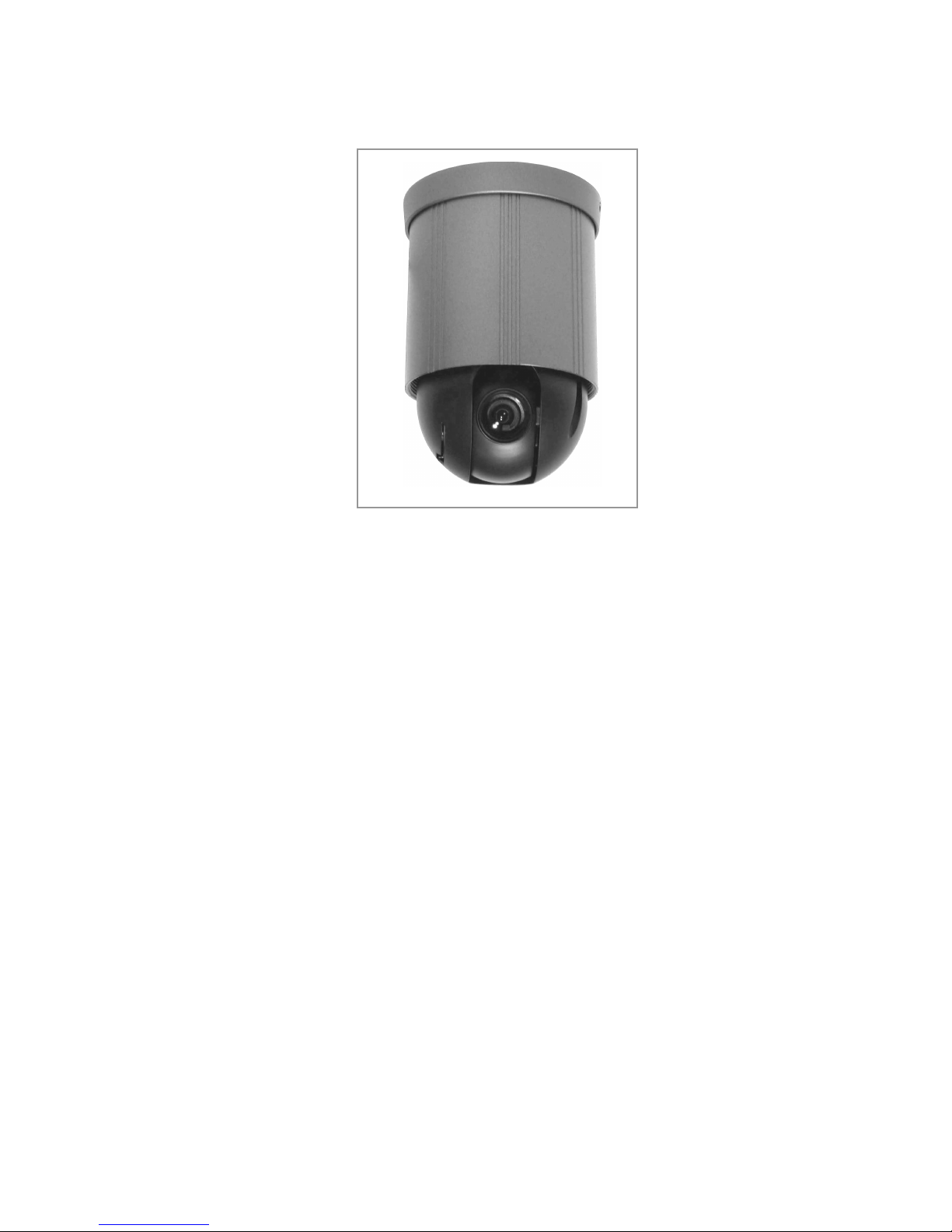
Appearance
Vidia Srl – Via Vasanello 23, 00189 Roma – Tel +39 0630316333 Fax +39 0630350231 www.vidia.it
Vidia Srl – Via Vasanello 23, 00189 Roma – Tel +39 0630316333 Fax +39 0630350231 www.vidia.it
5.1
To access DIP switches
Before the camera is mounted in place, be sure the following four settings are
properly executed, or the camera may fail the control:
Camera ID setup
Protocol selection
Baud rate selection
Terminator
(RS485 impedance)
setup
Tools:
1. Philips (or “plus type”) screw driver #2, for opening and putting back the cover
2. Pincer, paper clip or small flat screw driver, to move the lever of DIP switch
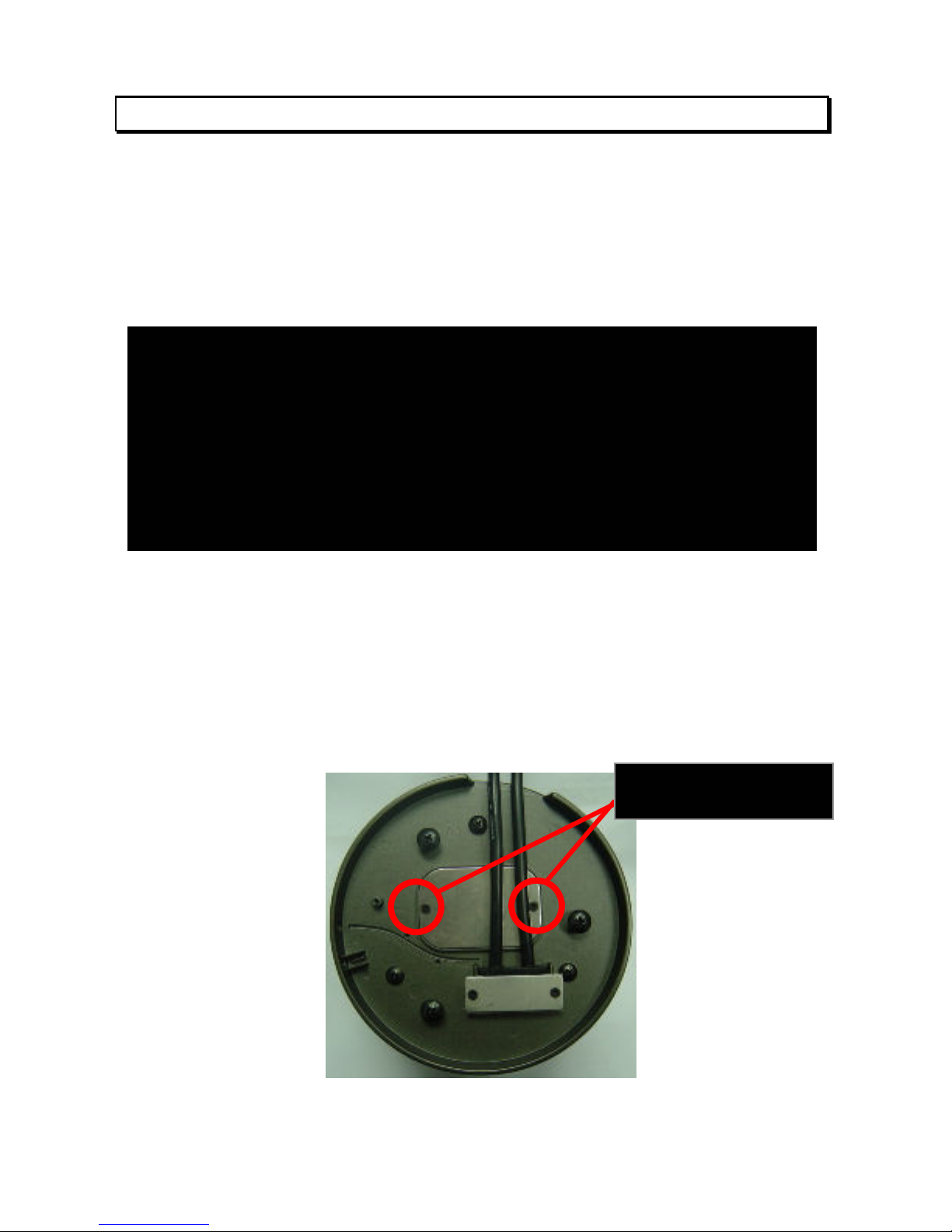
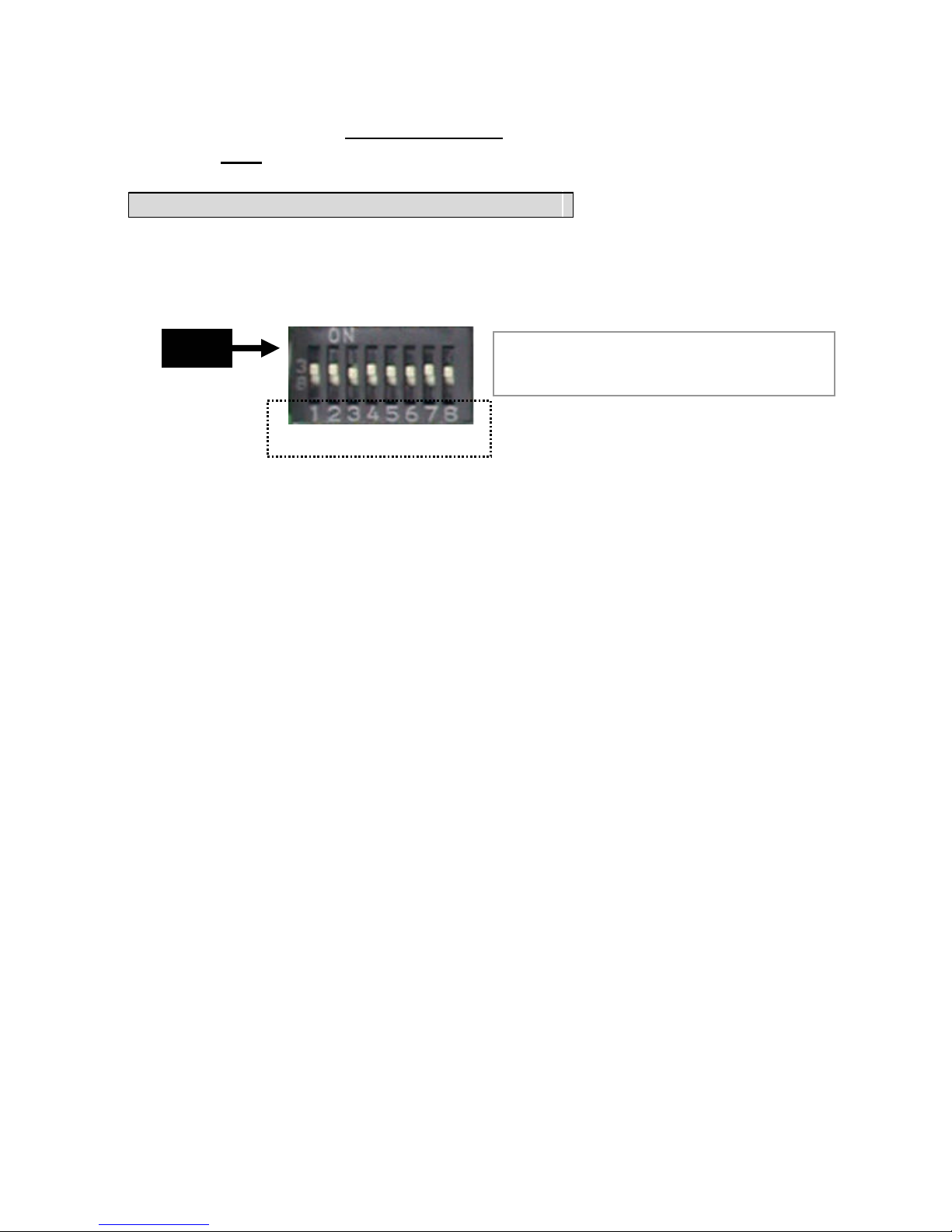
Access point to DIP switches for setups:
To open the cover, take the two screws off from bottom chassis, as the instruction on
below:
Important Notice
All the DIP switches for setting up camera ID, protocol, baud rate and RS485
terminator impedance are in the dome at the bottom side, and accessible via a
opening. In normal condition, this opening is sealed with a piece of steel cover.
The metal cover, together with a rubber around the opening, is for stopping
water and dust going the camera. Therefore, installer must be very careful
during the opening or putting back the steel cover.
Take these 2 screws
off
Vidia Srl – Via Vasanello 23, 00189 Roma – Tel +39 0630316333 Fax +39 0630350231 www.vidia.it
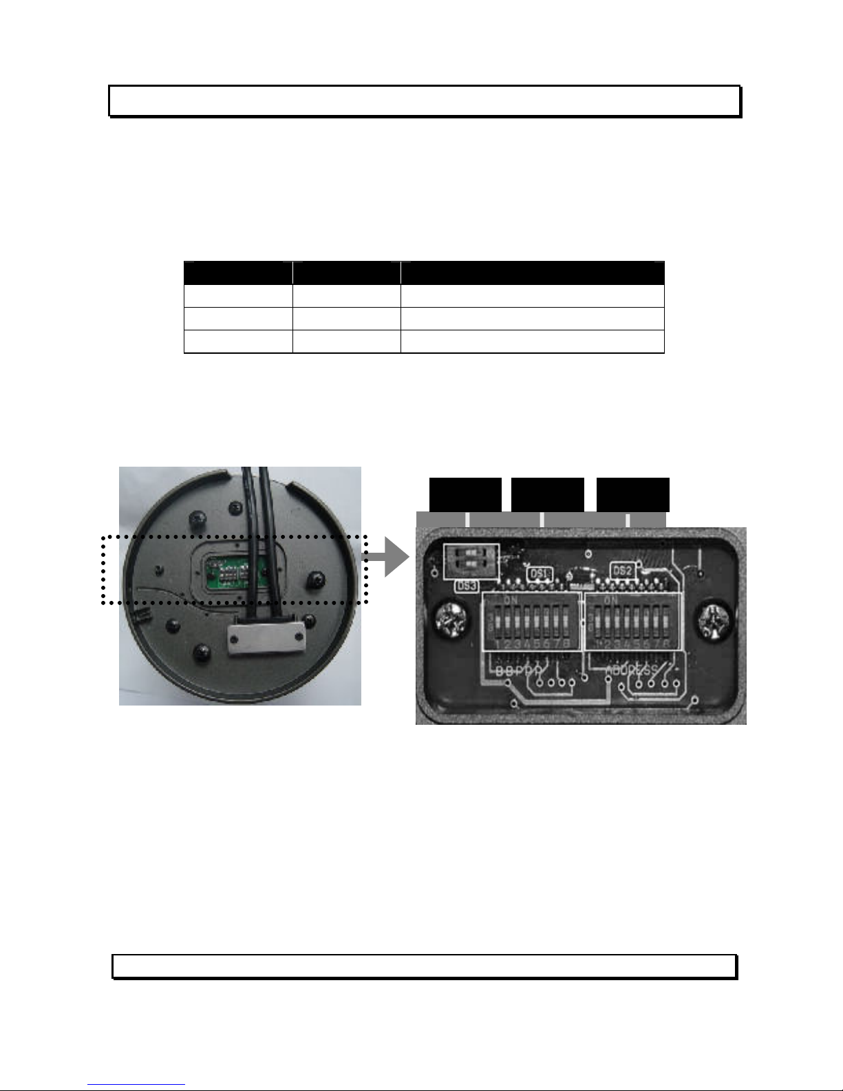
5.2
DIP switches
Overview of DIP switches
There are three sets of DIP switch on board for different setup purposes.
location # bit quantity used for
DS1 8 Protocol / baud rate setup
DS2 8 Device ID setup
DS3 2 Network impedance
Refer to the picture on below for DIP switch locations.
The following paragraphs are providing the detail descriptions of the three main
setups. Installer should read it with care, before starts doing the hardware mounting
and cabling work.
5.3
Set Up Device ID Number
DS3
DS1 DS2
Vidia Srl – Via Vasanello 23, 00189 Roma – Tel +39 0630316333 Fax +39 0630350231 www.vidia.it
To build correct network for control communication, every speed dome camera in
the network must have an unique ID number
, which is set by the bit 1 to 8 of a 8-bit
DIP switch DS2.
Note:
Factory default of device ID is 1
Find 8-bit DIP switch DS2 on the PC board
Refer to the tables in the next two pages for ID setting
(the tables shows the
relation between pin assignments of DIP switch and ID numbers 1 to 255)
The highest ID number of this camera is 255.
All the speed domes in a network must have their unique ID. It is highly
recommended to installers, for future maintenance efficiency and users’
convenience, to mark the ID of each camera onto its corresponding location on
the site map, and make out a list of cameras with their ID numbers.
The DS2 pin assignment for ID setup is in binary format.
remark: D
ash line “---“ in table means to
set the bit to “OFF” position
DS2
Bit number
Vidia Srl – Via Vasanello 23, 00189 Roma – Tel +39 0630316333 Fax +39 0630350231 www.vidia.it
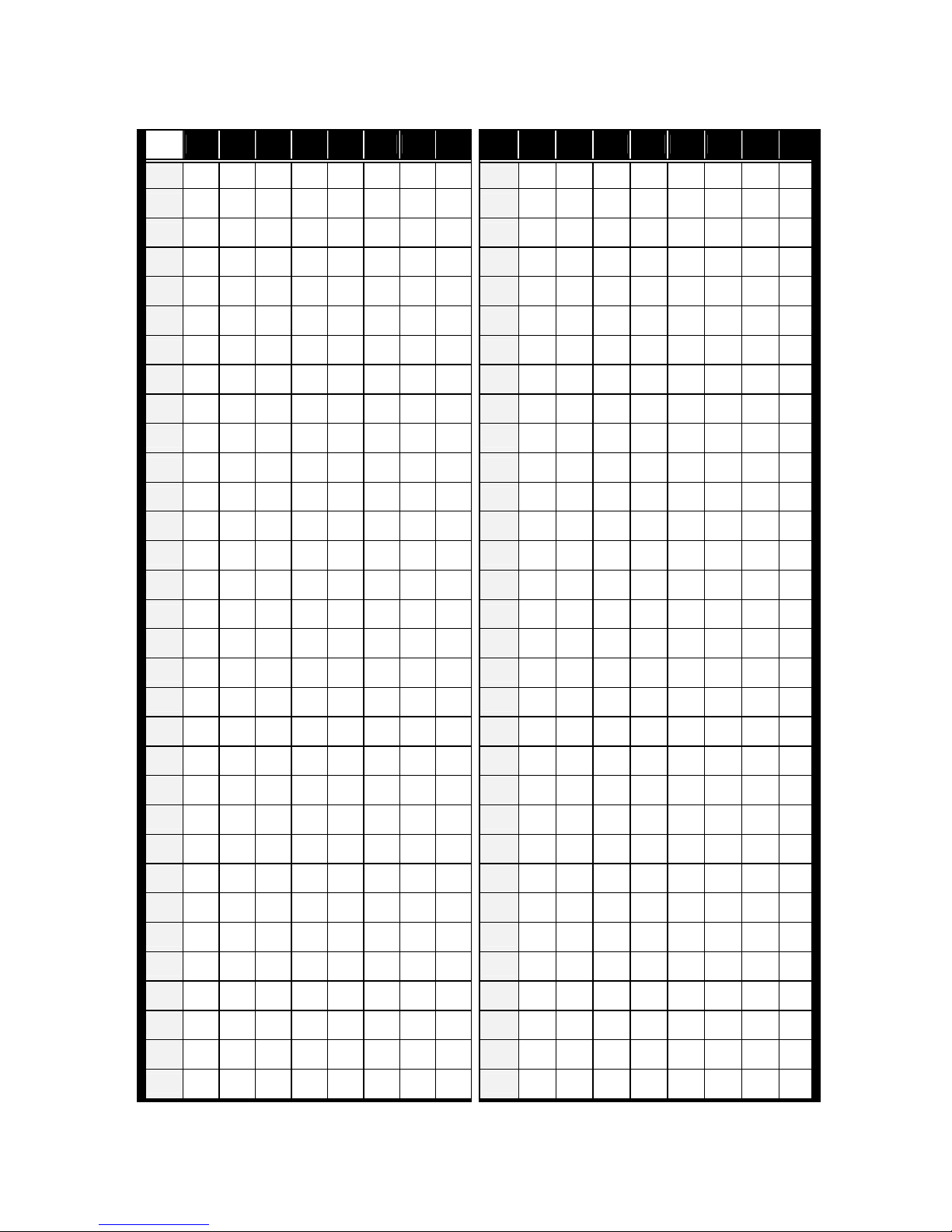
ID table (1 ~ 64)
ID 1 2 3 4 5 6 7 8 ID 1 2 3 4 5 6 7
8
1 -- -- -- -- -- -- -- -- 33 -- -- -- -- -- on --
--
2 on -- -- -- -- -- -- -- 34 on -- -- -- -- on --
--
3 -- on -- -- -- -- -- -- 35 -- on -- -- -- on --
--
4 on on -- -- -- -- -- -- 36 on on -- -- -- on --
--
5 -- -- on -- -- -- -- -- 37 -- -- on -- -- on --
--
6 on -- on -- -- -- -- -- 38 on -- on -- -- on --
--
7 -- on on -- -- -- -- -- 39 -- on on -- -- on --
--
8 on on on -- -- -- -- -- 40 on on on -- -- on --
--
9 -- -- -- on -- -- -- -- 41 -- -- -- on -- on --
--
10 on -- -- on -- -- -- -- 42 on -- -- on -- on --
--
11 -- on -- on -- -- -- -- 43 -- on -- on -- on --
--
12 on on -- on -- -- -- -- 44 on on -- on -- on --
--
13 -- -- on on -- -- -- -- 45 -- -- on on -- on --
--
14 on -- on on -- -- -- -- 46 on -- on on -- on --
--
15 -- on on on -- -- -- -- 47 -- on on on -- on --
--
16 on on on on -- -- -- -- 48 on on on on -- on --
--
17 -- -- -- -- on -- -- -- 49 -- -- -- -- on on --
--
18 on -- -- -- on -- -- -- 50 on -- -- -- on on --
--
19 -- on -- -- on -- -- -- 51 -- on -- -- on on --
--
20 on on -- -- on -- -- -- 52 on on -- -- on on --
--
21 -- -- on -- on -- -- -- 53 -- -- on -- on on --
--
22 on -- on -- on -- -- -- 54 on -- on -- on on --
--
23 -- on on -- on -- -- -- 55 -- on on -- on on --
--
24 on on on -- on -- -- -- 56 on on on -- on on --
--
25 -- -- -- on on -- -- -- 57 -- -- -- on on on --
--
26 on -- -- on on -- -- -- 58 on -- -- on on on --
--
27 -- on -- on on -- -- -- 59 -- on -- on on on --
--
28 on on -- on on -- -- -- 60 on on -- on on on --
--
29 -- -- on on on -- -- -- 61 -- -- on on on on --
--
30 on -- on on on -- -- -- 62 on -- on on on on --
--
31 -- on on on on -- -- -- 63 -- on on on on on --
--
32 on on on on on -- -- -- 64 on on on on on on --
--
Vidia Srl – Via Vasanello 23, 00189 Roma – Tel +39 0630316333 Fax +39 0630350231 www.vidia.it
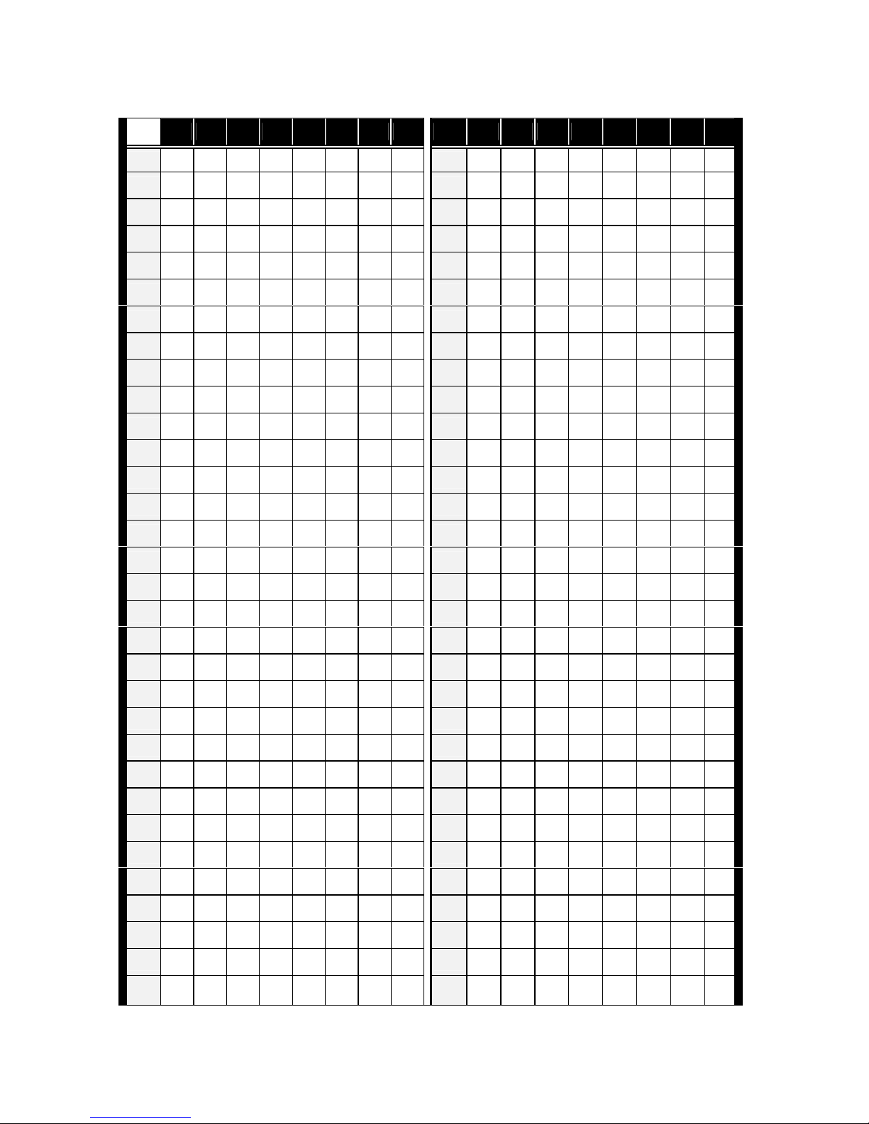
ID table (65 ~ 128)
ID
1 2 3 4 5 6 7 8 ID 1 2 3 4 5 6 7 8
65 -- -- -- -- -- -- on -- 97 -- -- -- -- -- on on --
66 on -- -- -- -- -- on -- 98 on -- -- -- -- on on --
67 -- on -- -- -- -- on -- 99 -- on -- -- -- on on --
68 on on -- -- -- -- on -- 100 on on -- -- -- on on --
69 -- -- on -- -- -- on -- 101 -- -- on -- -- on on --
70 on -- on -- -- -- on -- 102 on -- on -- -- on on --
71 -- on on -- -- -- on -- 103 -- on on -- -- on on --
72 on on on -- -- -- on -- 104 on on on -- -- on on --
73 -- -- -- on -- -- on -- 105 -- -- -- on -- on on --
74 on -- -- on -- -- on -- 106 on -- -- on -- on on --
75 -- on -- on -- -- on -- 107 -- on -- on -- on on --
76 on on -- on -- -- on -- 108 on on -- on -- on on --
77 -- -- on on -- -- on -- 109 -- -- on on -- on on --
78 on -- on on -- -- on -- 110 on -- on on -- on on --
79 -- on on on -- -- on -- 111 -- on on on -- on on --
80 on on on on -- -- on -- 112 on on on on -- on on --
81 -- -- -- -- on -- on -- 113 -- -- -- -- on on on --
82 on -- -- -- on -- on -- 114 on -- -- -- on on on --
83 -- on -- -- on -- on -- 115 -- on -- -- on on on --
84 on on -- -- on -- on -- 116 on on -- -- on on on --
85 -- -- on -- on -- on -- 117 -- -- on -- on on on --
86 on -- on -- on -- on -- 118 on -- on -- on on on --
87 -- on on -- on -- on -- 119 -- on on -- on on on --
88 on on on -- on -- on -- 120 on on on -- on on on --
89 -- -- -- on on -- on -- 121 -- -- -- on on on on --
90 on -- -- on on -- on -- 122 on -- -- on on on on --
91 -- on -- on on -- on -- 123 -- on -- on on on on --
92 on on -- on on -- on -- 124 on on -- on on on on --
93 -- -- on on on -- on -- 125 -- -- on on on on on --
94 on -- on on on -- on -- 126 on -- on on on on on --
95 -- on on on on -- on -- 127 -- on on on on on on --
96 on on on on on -- on -- 128 on on on on on on on --

Vidia Srl – Via Vasanello 23, 00189 Roma – Tel +39 0630316333 Fax +39 0630350231 www.vidia.it
ID table (129 ~ 192)
ID 1 2 3 4 5 6 7 8 ID 1 2 3 4 5 6 7
8
129 -- -- -- -- -- -- -- on 161 -- -- -- -- -- on -- on
130 on -- -- -- -- -- -- on 162 on -- -- -- -- on -- on
131 -- on -- -- -- -- -- on 163 -- on -- -- -- on -- on
132 on on -- -- -- -- -- on 164 on on -- -- -- on -- on
133 -- -- on -- -- -- -- on 165 -- -- on -- -- on -- on
134 on -- on -- -- -- -- on 166 on -- on -- -- on -- on
135 -- on on -- -- -- -- on 167 -- on on -- -- on -- on
136 on on on -- -- -- -- on 168 on on on -- -- on -- on
137 -- -- -- on -- -- -- on 169 -- -- -- on -- on -- on
138 on -- -- on -- -- -- on 170 on -- -- on -- on -- on
139 -- on -- on -- -- -- on 171 -- on -- on -- on -- on
140 on on -- on -- -- -- on 172 on on -- on -- on -- on
141 -- -- on on -- -- -- on 173 -- -- on on -- on -- on
142 on -- on on -- -- -- on 174 on -- on on -- on -- on
143 -- on on on -- -- -- on 175 -- on on on -- on -- on
144 on on on on -- -- -- on 176 on on on on -- on -- on
145 -- -- -- -- on -- -- on 177 -- -- -- -- on on -- on
146 on -- -- -- on -- -- on 178 on -- -- -- on on -- on
147 -- on -- -- on -- -- on 179 -- on -- -- on on -- on
148 on on -- -- on -- -- on 180 on on -- -- on on -- on
149 -- -- on -- on -- -- on 181 -- -- on -- on on -- on
150 on -- on -- on -- -- on 182 on -- on -- on on -- on
151 -- on on -- on -- -- on 183 -- on on -- on on -- on
152 on on on -- on -- -- on 184 on on on -- on on -- on
153 -- -- -- on on -- -- on 185 -- -- -- on on on -- on
154 on -- -- on on -- -- on 186 on -- -- on on on -- on
155 -- on -- on on -- -- on 187 -- on -- on on on -- on
156 on on -- on on -- -- on 188 on on -- on on on -- on
157 -- -- on on on -- -- on 189 -- -- on on on on -- on
158 on -- on on on -- -- on 190 on -- on on on on -- on
159 -- on on on on -- -- on 191 -- on on on on on -- on
160 on on on on on -- -- on
192 on on on on on on -- on

Vidia Srl – Via Vasanello 23, 00189 Roma – Tel +39 0630316333 Fax +39 0630350231 www.vidia.it
ID table (193 ~ 255)
ID
1 2 3 4 5 6 7 8 ID 1 2 3 4 5 6 7 8
193 -- -- -- -- -- -- on on 225 -- -- -- -- -- on on on
194 on -- -- -- -- -- on on 226 on -- -- -- -- on on on
195 -- on -- -- -- -- on on 227 -- on -- -- -- on on on
196 on on -- -- -- -- on on 228 on on -- -- -- on on on
197 -- -- on -- -- -- on on 229 -- -- on -- -- on on on
198 on -- on -- -- -- on on 230 on -- on -- -- on on on
199 -- on on -- -- -- on on 231 -- on on -- -- on on on
200 on on on -- -- -- on on 232 on on on -- -- on on on
201 -- -- -- on -- -- on on 233 -- -- -- on -- on on on
202 on -- -- on -- -- on on 234 on -- -- on -- on on on
203 -- on -- on -- -- on on 235 -- on -- on -- on on on
204 on on -- on -- -- on on 236 on on -- on -- on on on
205 -- -- on on -- -- on on 237 -- -- on on -- on on on
206 on -- on on -- -- on on 238 on -- on on -- on on on
207 -- on on on -- -- on on 239 -- on on on -- on on on
208 on on on on -- -- on on 240 on on on on -- on on on
209 -- -- -- -- on -- on on 241 -- -- -- -- on on on on
210 on -- -- -- on -- on on 242 on -- -- -- on on on on
211 -- on -- -- on -- on on 243 -- on -- -- on on on on
212 on on -- -- on -- on on 244 on on -- -- on on on on
213 -- -- on -- on -- on on 245 -- -- on -- on on on on
214 on -- on -- on -- on on 246 on -- on -- on on on on
215 -- on on -- on -- on on 247 -- on on -- on on on on
216 on on on -- on -- on on 248 on on on -- on on on on
217 -- -- -- on on -- on on 249 -- -- -- on on on on on
218 on -- -- on on -- on on 250 on -- -- on on on on on
219 -- on -- on on -- on on 251 -- on -- on on on on on
220 on on -- on on -- on on 252 on on -- on on on on on
221 -- -- on on on -- on on 253 -- -- on on on on on on
222 on -- on on on -- on on 254 on -- on on on on on on
223 -- on on on on -- on on 255 -- on on on on on on on
224 on on on on on -- on on
Vidia Srl – Via Vasanello 23, 00189 Roma – Tel +39 0630316333 Fax +39 0630350231 www.vidia.it
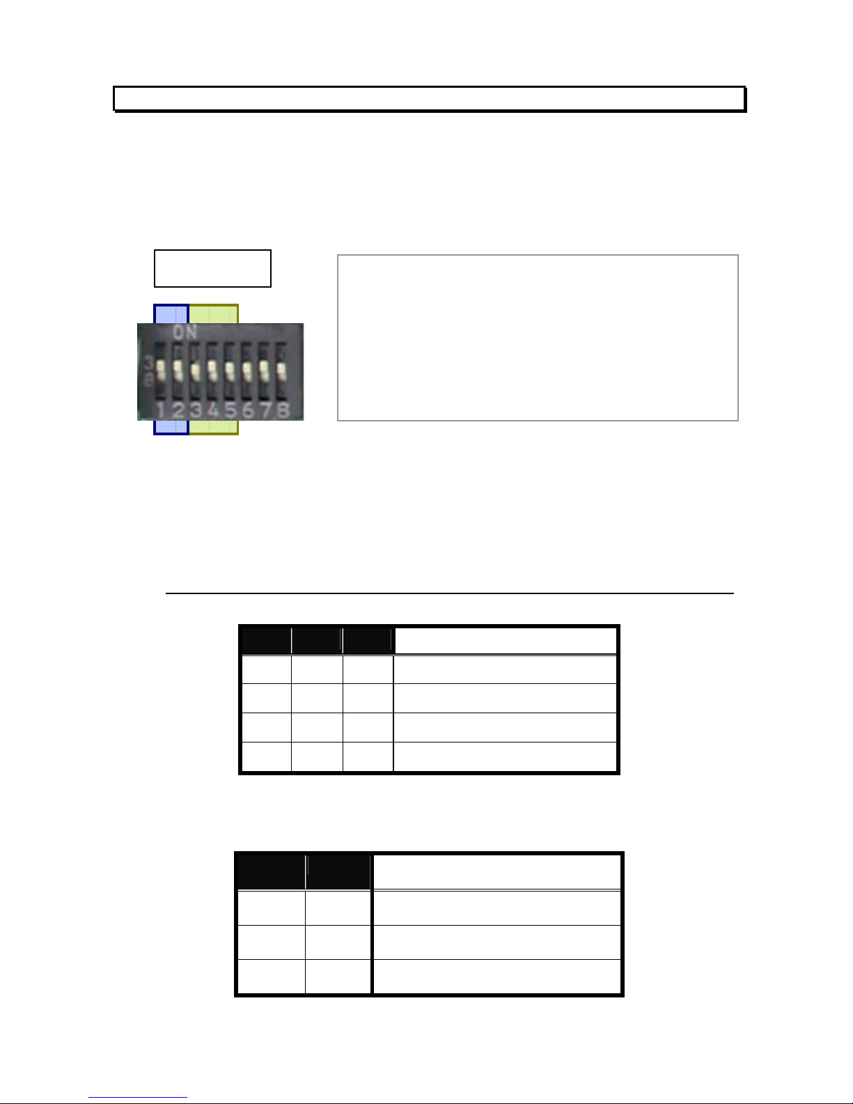
5.4
Control Protocol and Baud Rate
Control protocol and baud rate must be set correctly to the camera in order to
establish proper communication between the camera and control device.
Be sure that the same protocol and baud rate are selected in control device, too.
Presently 2 types of protocol and 3 levels of baud rate are provided by this speed
dome, through an 8-bit DIP switch labeled DS1.
First, installer needs to choose a communication protocol with bit number 3, 4
and 5. Watch that the same protocol is chosen for speed dome and controller.
The following table shows the three protocols provided in this speed dome.
Check what are available in the controller before choosing the protocol.
3 4 5
Protocol
-- -- --
Pelco-D
on -- --
Pelco-P
-- on --
Reserved
on on --
Reserved
Bit 1 and 2 are for baud rate setup. Same baud rate must be set up for the
speed dome and control device, or communication for control will fail.
1 2 Baud rate
-- --
2,400 bps
on --
4,800 bps
-- on
9,600 bps
remark:
A. “--“ means to set the bit to “OFF” position
B. Bit 1 and 2 are for baud rate setup
C. Bit 3, 4 and 5 are for protocol selection
D. Bit 6 is reserved future use
E. Bit 7 is for firmware upgrade mode
F. Bit 8 is for cooling fan on / off switching
DS 1

Vidia Srl – Via Vasanello 23, 00189 Roma – Tel +39 0630316333 Fax +39 0630350231 www.vidia.it
5.5
RS485 Network and Impedance
Transmission distances of RS485 Bus
The 0.56mm (AWG#24) twisted pair or higher grade wires are recommended for
data transmission cable
The maximum theoretical transmitting distances, for the AWG#24, are as follows:
Baud Rate Maximum Transmitting Distance
2400 Bps 1800m
4800 Bps 1200m
9600Bps 800m
If user selects thinner cables, or installs the dome in an environment surrounded by
strong electromagnetic interference, or connects lots of equipment to the RS485
bus, the maximum transmitting distance will decrease. To increase the maximum
transmitting distance, do the opposite way, i.e. use thicker wire and keep the cable
away from the interference.
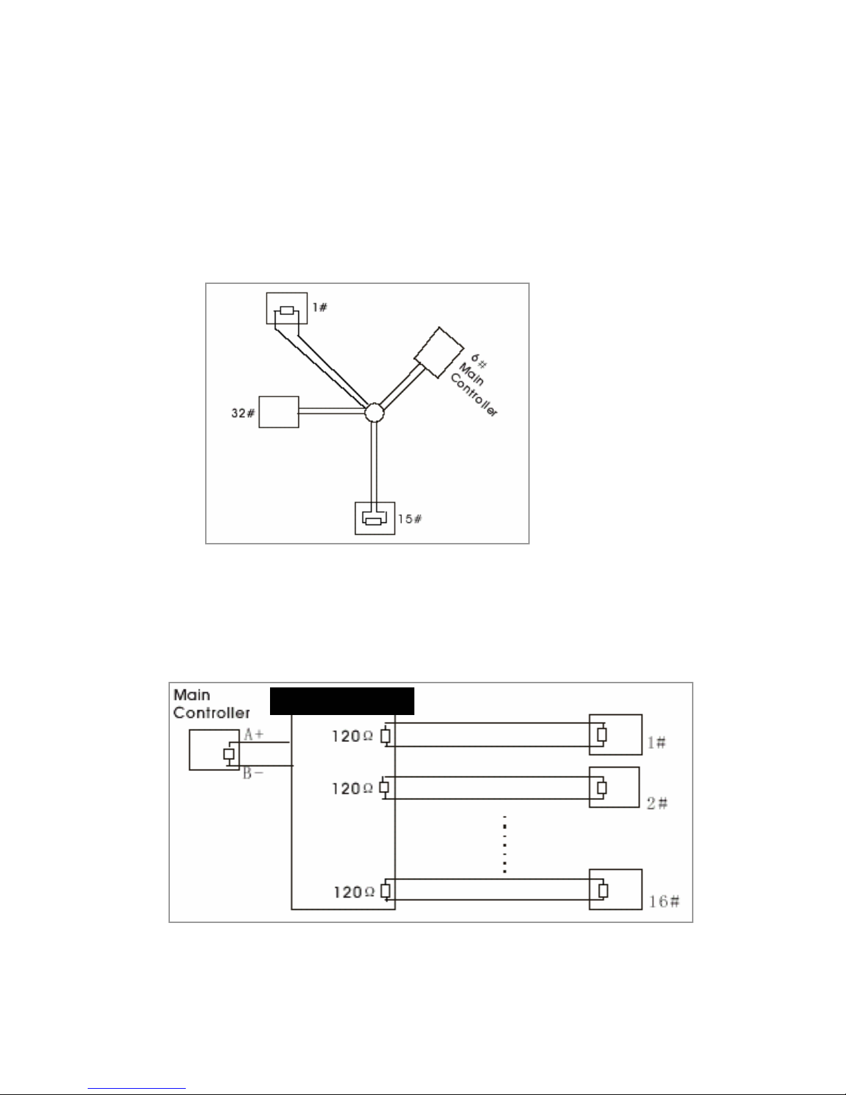
Connection and terminator resistor
The RS485 requires daisy-chain connection among the equipments. There must be
terminator resistors for impedance matching (typically 120 ohms, within the range
from 90 to 250 ohms). Terminators are to be located at both ends of each RS-485
net.
Impedance setup for the speed dome
120£[
1 2 3#
32
120£[
D
A+
B-
A+ B-
. . . . .
. . . . .
120O 120O
1# 2# 3# 4# 32#
. . . . .
Vidia Srl – Via Vasanello 23, 00189 Roma – Tel +39 0630316333 Fax +39 0630350231 www.vidia.it
Each speed dome camera has a switchable terminator resistor built in, which is set
to OFF position as the factory default.
In a network of RS485 chain, the speed domes are classified in two categories:
end unit
(unit #1 and #32)
and node
(#2 through #31). refer to chart in previous page.
To set up the resistor correctly, installer must decide if the specific dome camera is
the termination device or not, i.e. if it is at the end of the RS485 chain.
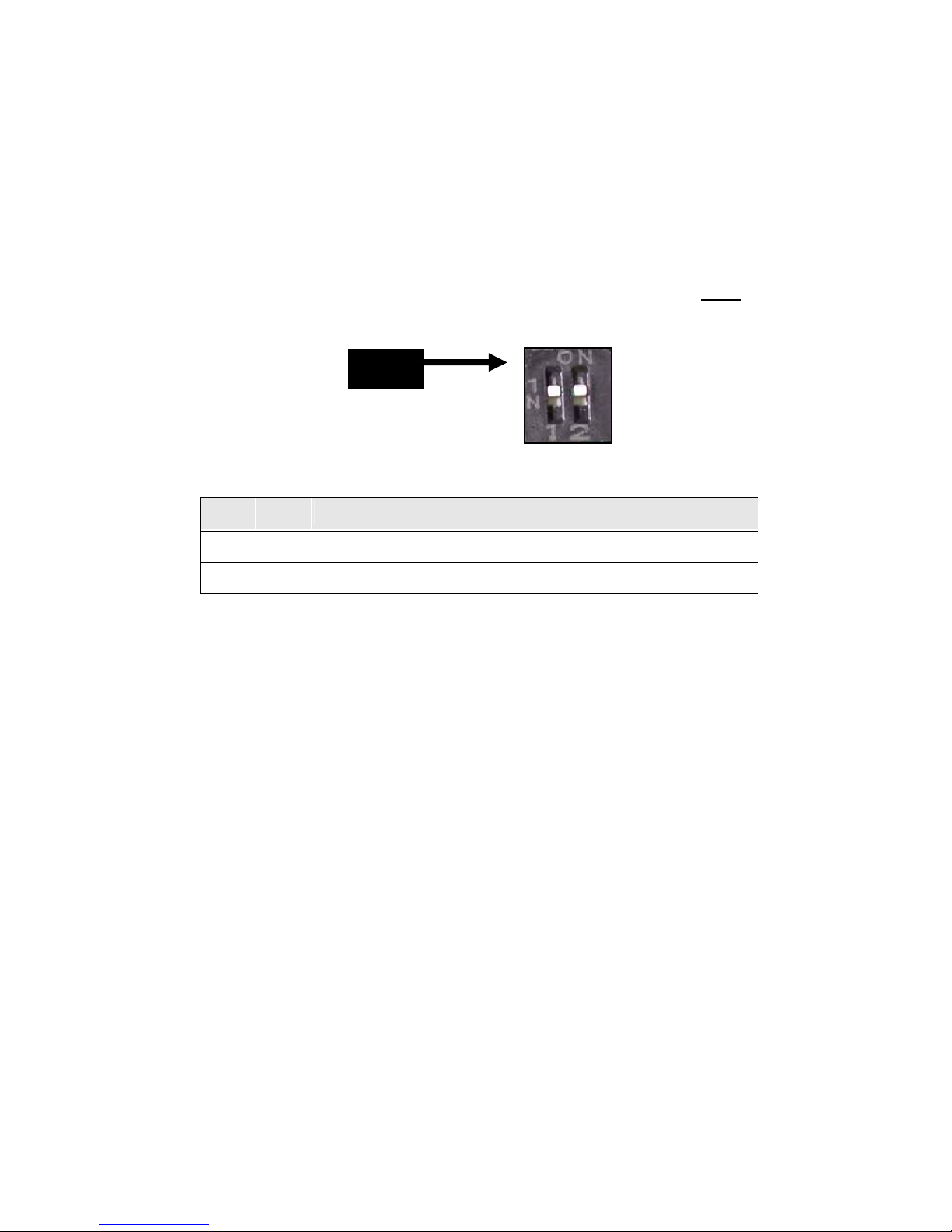
The impedance setup is provided by the bit 1 and bit 2 of DIP switch
DS3
.
Bit 1
Bit 2
Impedance
-- --
Open ( device on node )
On On
Standard 120 ohms ( device at end )
For nodes: Set both of Bit 1 and Bit 2 to OFF position
For end unit: Set both of Bit 1 and Bit 2 to ON position
Impedance of the control unit
This is generally for two cases: controller with RS485, and controller with RS232.
Controller with RS485:
Most keyboard and video server in market have RS485, and are equipped with
terminator resistor to drive a RS485 system.
Controller with RS-232
But most PC and notebook sort of devices have RS232 or USB port but no
RS485. Therefore, for PC system, a RS232 or USB to RS485 converter is neded.
Installer must check out if the converter has proper terminator resistor.
Problems in practical connection
DS3
Vidia Srl – Via Vasanello 23, 00189 Roma – Tel +39 0630316333 Fax +39 0630350231 www.vidia.it
In some circumstances user adopts a star configuration in practical connection. The
terminator resistors must be connected to the two equipment that are farthest away
from each other, such as equipment 1# and 15# in the following picture. As the star
configuration is not in conformity with the requirements of RS485 standards,
problems such as signal reflections, lower anti-interference performance arise when
the cables are long in the connection. The reliability of control signals could be
downgraded with the phenomena that your dome camera does not respond to or
just responds at intervals to the controller, or does continuous operation without stop
In such circumstances the usage of RS485 distributor is recommended. The
distributor can change the star configuration connection to the mode of connection
stipulated in the RS485 standards. The new connection achieves reliable data
transmission.
RS485 distributor

Vidia Srl – Via Vasanello 23, 00189 Roma – Tel +39 0630316333 Fax +39 0630350231 www.vidia.it
6. Mount The Dome Camera
There are 3 (Three) ways to mount the PTZ camera, which are:
1.
Attached to the ceiling surface directly
2.
Held to ceiling surface through a bracket
3.
Mounted to wall through a bracket
Please find the accessory information in the list on the next page to get
understand of what component is for which mounting.

Vidia Srl – Via Vasanello 23, 00189 Roma – Tel +39 0630316333 Fax +39 0630350231 www.vidia.it
6.1
Mounting Accessory
The following items are supplied with the speed dome for the camera mounting.
Description Photo Use
1
Mounting base
a
To hold the camera
on ceiling surface
b
Used together with
item # 2 (bowl type
holder) for ceiling
hold or wall mount
2
Metal bowl
holder
To work with item 1 for
creating ceiling or wall
mount
3
Screw pack
Screws for the build of
camera’s holding
structure

Vidia Srl – Via Vasanello 23, 00189 Roma – Tel +39 0630316333 Fax +39 0630350231 www.vidia.it
In case of dealing with a
concrete
wall
:
a. Mark the locations for screw through the holes on the base
b. Make holes on the wall, then insert the supplied plastic plugs into
the holes and squeeze them in until they are flush with the wall
surface.
c. Mount the base on the desired place tightly with screws
6.2
Surface mount onto Ceiling
1.
Locate the base onto the place the camera is to mount, and fix the base on
the place tightly with screws through the 3 holes on the
base
(be sure screws are complete in the ceiling)
2.
Get the camera and secure it to the base with the
supplied metal chain.
3.
Then fit the camera body to the base, rotate the camera
body clockwise until it is completely locked into position.
4.
Put the screw A
(anti-loss)
in position and screw it in

Vidia Srl – Via Vasanello 23, 00189 Roma – Tel +39 0630316333 Fax +39 0630350231 www.vidia.it
6.3
Wall-mounting
To mount the camera from ceiling, a metal wall-mount bracket in separate package
will be needed.
The mounting procedure
Step 1
Get the metal bowl and mounting base, put
them together with screws to make them a
sub-assembly for mounting.
Step 2
Hook the sub-assembly and camera with the safety cable located on the
bottom of camera
(left picture on below
), then put the signal cables
throughout the sub-assembly
(right picture)
.
Step 3
Fasten the sub-assembly and
camera together. Rotate camera
all the way clockwise. Fix the
base to camera with the supplied
screw and wrench.
Step 4
Get the wall-mount bracket. Remove the metal cover (sheet) from the
bracket
Fig-1

Vidia Srl – Via Vasanello 23, 00189 Roma – Tel +39 0630316333 Fax +39 0630350231 www.vidia.it
Step 5
Mount the bracket onto wall (Fig-2) but DO NOT tight the bracket to wall
completely until the Step 6 and 7 are finished.
Caution: Be sure the wall is strong enough to hold the entire
device (i.e. housing + camera)
Step 6
Lay all the signal cables
(RS485, video, power and alarm-wires)
in the trench
of bracket, and have all connectors come out bracket through the cable
outlet
(Fig-3)
.
Step 7
Fix and tighten the camera module (assembly) to the bracket with
supplied screws
Fig-4
Step 8
Put the cover back to holderFig-5
Fig-1
Fig-2
Fig-3
Fig-4
Fig-5

Vidia Srl – Via Vasanello 23, 00189 Roma – Tel +39 0630316333 Fax +39 0630350231 www.vidia.it
6.4
Ceiling -drop
To mount the camera from ceiling, a metal wall-mount bracket in separate package
will be needed.
The mounting procedure
Step 1
Get the metal bowl and mounting base, put
them together with screws to make them a
sub-assembly for mounting.
Step 2
Hook the sub-assembly and camera with the
safety cable located on the bottom of camera
(left picture on below
), then
put the signal cables throughout the sub-assembly
(right picture)
.
Step 3
Fasten the sub-assembly and camera
together at the joint of D-sub
connectors. Rotate camera all the way
in direction of clockwise. Fix the base
to camera with the supplied screw and
wrench.
step 4
Get the ceiling mount bracket. Put cables into the
tube,
advise: start with the 9-pin alarm I/O; Take the male
part off to reduce connector size, to make
cabling through tube easier ).
Have all connectors come out the tube from cable
outlet near the top of the bracket.
Step 5
Fasten the camera module (sub-assembly) to

Vidia Srl – Via Vasanello 23, 00189 Roma – Tel +39 0630316333 Fax +39 0630350231 www.vidia.it
the bracket with the supplied screws
Step 6
Mount the bracket onto ceiling and tight the bracket completely.
Caution: Be sure the wall is strong enough to hold the entire
device (i.e. housing + camera)
The figure on below shows how it looks like when ceiling-drop is finished

Vidia Srl – Via Vasanello 23, 00189 Roma – Tel +39 0630316333 Fax +39 0630350231 www.vidia.it
7. Connecting Wires
The cables, wires and connector attached to the speed dome are categories into 4
major functions of:
1.
Power
2.
Video
3.
RS485
4.
Alarm-in and out
They are easily distinguished from one to another, as being featured with different
connectors. Refer to the picture on below to learn about cable and connector
information.

Vidia Srl – Via Vasanello 23, 00189 Roma – Tel +39 0630316333 Fax +39 0630350231 www.vidia.it
7.1
Power
The camera has two versions for power: DC12V or AC24V.
1. DC12V:
When operated with DC12V, the camera may consume 1000mA DC current in
full load condition. To secure the safety and maintain correct function, always
use the 12V / 1.5A DC adapter supplied by the manufacturer.
To power the speed dome is simple. Get the DC jack from the camera, and
connect the adapter plug to the jack.
2. AC24V: (AC adapter of 24V / 1.66A is optional.)
An AC adapter of 24V / 1.66A is supplied with the camera / housing for the AC
version. To power the camera, connect adapter to camera’s power connector.
Power Connector on Speed Dome
AC 24V Connector on Adaptor
As soon as power is supplied, the speed dome will enter “initial check” mode with
the following procedures:
Move the lens around automatically for system check and calibration
Screen will show blue picture words in white for around 5 seconds
Then the camera will show normal image and get ready for control
7.2
Video
DC 12V adapter
(supplied)

Vidia Srl – Via Vasanello 23, 00189 Roma – Tel +39 0630316333 Fax +39 0630350231 www.vidia.it
Video output of 1Vp-p is delivered at the female BNC end with 75 ohms impedance.
To transmit the video to receiver properly, it is recommended to use RG59 A/U
coaxial cable with stranded center conductor, with male BNC connectors on both
ends.
RG59 is also in 75 ohm impedance, which matches the
camera’s output impedance. The A/U version is recommended,
rather than the version B/U, due of its superior performance on
flexibility for resisting severe twisting, bending and other
stresses which occur in many CCTV installations.
In case the installation distance is over than 500 meters (1,500 feet), additional
amplifier might be needed to keep the video level and image quality.
If superior video quality is strongly demanded, you may need to add the video buffer
for each 300 meters or even 250 meters.
7.3
RS485
The camera adapts RS485 in half-duplex pattern, a two-pin
connectivity as shown on the right picture.
Installer must pay attention to the polarity of these two pins –
yellow wire is the POSITIVE end, and orange is the
NEGATIVE. Communication between controller and camera
will break and control will not function if they are reversely
connected.
The RS485 communication may run for 4,000 feet if the system network is properly
built. Two important factors should be handled with care during the system
build-up--- baud rate and termination impedance. More information about RS485
are in sections “Protocol and Baud rate” and “Applications”.
7.4
Alarm Input & Alarm Output
yellow
+
--
orange

Vidia Srl – Via Vasanello 23, 00189 Roma – Tel +39 0630316333 Fax +39 0630350231 www.vidia.it
This camera is equipped with 3 alarm-in and one alarm-out for intrusion
management. Installers may connect the inputs to various sensors and program the
camera to move to specific spots for visual check when evens take place. Dwell time
is programmable, subject to the controller
(some controllers don’t offer the access to
dwell setting)
Refer to the table on below for function assignments to each alarm I/O.
Alarm in Wire Color Alarm GND Wire Color Alarm out Wire Color
Alarm in 1 Black Alarm 1 Brown N.O. Gray
Alarm in 2 Red Alarm 2 Orange N.C. Purple
Alarm in 3 Yellow Alarm 3 Green Com. Blue
Alarm inputs
This speed dome has three alarm inputs, and each input is given by the software a
companion view preset. When trigger single is sent to alarm-in, the following
reactions will be taken by the speed dome:
The pan-tilt mechanism will move lens to the preset.
The alarm-out port will act.
Via RS485, the console (control unit) will be notified
The three inputs and their correspondent view presets are independent from one to
another. Therefore, with the connections to three sensors, installer can set up
camera to monitor three different spots with different dwell time.
Presets For Events
Default settings at the alarm-ins activations are:
If setting(s) is / are done to presets 17, 18 and 19 :
At the trigger of alarm-in number 1, lens will move to preset 17.
At the trigger of alarm-in number 2, lens will move to preset 18.
At the trigger of alarm-in number 3, lens will move to preset 19.
If one or more positions of presets 17, 18 and 19 is / are empty:
At the trigger of alarm 1, lens will move to preset 1
(preset 17 is empty)
At the trigger of alarm 2, lens will move to preset 2
(preset 18 is empty)
At the trigger of alarm 3, lens will move to preset 3
(preset 19 is empty)
Note
:
All the three alarm inputs are TTL level and triggered by negative signals.
To utilize the default view positions, user must pre-set
the desired monitor
spots to presets number 17, 18 and 19 (or 1, 2 and 3).

Vidia Srl – Via Vasanello 23, 00189 Roma – Tel +39 0630316333 Fax +39 0630350231 www.vidia.it
Alarm-ON Management Protocol
With the arrangements pre-defined in its software, the PTZ camera will perform the
following surveillance functions automatically at the triggering(s) to alarm-input(s):
Camera is running Auto-run when alarm signal(s) kicks in
1. When the first alarm signal hits this camera, camera will move to the
corresponding presets (see relative information on above ) at its maximum
speed of 240o per second
2. Camera will stay at the preset position for 60 seconds
3. Camera will be back to the original auto-pan function after 60 seconds, if
no second alarm-in jumps in this 60 second time frame.
4. In case the second and third alarms occur during the 60 seconds, camera
will move to the preset set for alarm-2, stay there for 10 seconds, then
move to the next preset set for alarm-3, stay for 5 seconds and keeps
moving around these presets until the 60 second time frame is over.
5. Camera will be back to its original auto-run function after the 60 seconds.
Camera is in steady mode when alarm signal(s) kicks in
1. When the first alarm signal hits this camera, camera will move to the
corresponding presets (see relative information on above ) at maximum
speed of 240o per second
2. Camera will stay at the preset position for 60 seconds
3. Camera will be back to the original position after 60 seconds, if no second
alarm-in jumps in this 60 second time frame.
4. I In case the second and third alarms occur during the 60 seconds, camera
will move to the preset set for alarm-2, stay there for 10 seconds, then
move to the next preset set for alarm-3, stay for 5 seconds and keeps
moving around these presets until the 60 second time frame is over.
5. Camera will be back to its original position after the 60 seconds.

Vidia Srl – Via Vasanello 23, 00189 Roma – Tel +39 0630316333 Fax +39 0630350231 www.vidia.it
Alarm output
The alarm output is a hardware toggle switch of NC (normal close) and NO (normal
open). In the event the camera receives trigger signal from one of the three
alarm-inputs, the two output ports will exchange their states (i.e. NC port will turn
into OPEN condition, and NO port will become CLOSE). This is used for activating
various external alarm devices, such as siren, recorder, alarm-light or call-out
system.
Alarm-on status will be automatically relieved at the 30th minute from the triggering
point and PTZ will be back to the original conditions. To relief system the alarm-on
status manually, use the MANUAL OFF on the controller (subject to the function’s
availability to the controller)
Warning
:
The NC/NO port provided by alarm-out is a mechanical contact relay.
Make sure the device connected to the alarm-output does not drain
current
over than 0.5A and the voltage is not higher than DC 24V or AC 250V.
Any load over these may damage the alarm output port permanently.

Vidia Srl – Via Vasanello 23, 00189 Roma – Tel +39 0630316333 Fax +39 0630350231 www.vidia.it
8 Applications
The PTZ camera, by itself alone or encompassed in different numbers of domes
with comprehensive matrix switching, is mainly for link to 4 different control means
(also known in different terms such as controller, console or host):
PC-based system
Keyboard controller
DVR
(Digital Video Recorder )
Video server
8.1
Controllers and RS485
While most keyboards, DVRs and video servers are equipped with RS485 port,
which can be directly connected to speed dome, desk top and notebook computers
usually don’t provide direct output of RS485. Therefore an interface device (signal
converter) will be needed when computer is used as the controller.
Note:
Check the PC first to see if RS232 port or USB port is available to the specific unit.
Some may have both while others only have one of the two.
If you need the RS232 or USB to RS485 converter, check with your
camera supplier for the information.
RS485
co
nverter

Vidia Srl – Via Vasanello 23, 00189 Roma – Tel +39 0630316333 Fax +39 0630350231 www.vidia.it
8.2
Connect RS485
from
dome
to
console
Connect the RS485 of camera to controller
(such as a keyboard
) with a pair of
twisted cable. Tele-control to speed dome will be executed via this cable.
Connect camera’s video signal to multiplexer, monitor, DVR or video server
directly.
Power (DC12V or AC24V) shall be applied to the camera via separate DC or
AC adapter.
If there is only one PTZ camera connected to the controller, leave the
terminator resistor in the PTZ camera OPEN.
Select proper control protocol and baud rate at the controller and the speed
dome. Be sure both sides (camera / controller) have the same protocol and
baud rate.
Connect
to keyboard +
monitor
Connect
to keyboard + MUX
Connect
Speed dome to standalone DVR

Vidia Srl – Via Vasanello 23, 00189 Roma – Tel +39 0630316333 Fax +39 0630350231 www.vidia.it
Connect the RS485 of camera to controller
(in this case, the DVR
) with a pair of
twisted cable. Tele-control to speed dome will be conducted from the DVR via
the cable.
Connect video signal to a multiplexer, matrix or DVR. If video is sent to a
multiplexer or matrix instead of DVR, it needs to be relayed to DVR via the MUX
or matrix for making record.
Power (DC12V) shall be applied to the camera independently with the supplied
power adaptor.
Set the terminator resistor in speed dome to OPEN position, if only one speed
dome is connected to the controller.
If two or more speed domes are in the system, the terminator resistor of END
unit must be loaded
(more information is in the next section)
.
Select a proper protocol and corresponding baud rate for the DVR. Be sure
both sides (PTZ camera and DVR) have the same protocol and baud rate.
In case the DVR does not have PTZ control function, use a separate keyboard
for the camera control. Protocol shall be properly selected, too.
P o w e r
A d a p t e r
RS-485
M o n i to r
D V R
D o m e D o m e D o m eD o m e
R S - 4 8 5
R S - 4 8 5
Video
P o w e r
A d a p t er
P o w e r
A d a p t er
P o w e r
A d a p t er
Video
Video
Video
P o w e r
A d a p te r
RS-485
M o n i t o r
D V R
D o m e D o m e D o m e
K e y b o a rd
D o m e
R S - 4 8 5
R S - 4 8 5
Video
P o w e r
A d a p te r
P o w e r
A d a p te r
P o w e r
A d a p te r
Video
Video
Video

Vidia Srl – Via Vasanello 23, 00189 Roma – Tel +39 0630316333 Fax +39 0630350231 www.vidia.it
Video server, the contemporary device for conducting surveillance through LAN and
WAN, can also be the controlling tool for this speed dome camera.
Most video servers in market are built with RS485 port and one video-in for
connecting one camera. To work with this speed dome, installer must connect both
signals
(video and RS485)
from the server to the camera, as the picture shown on
below.
First of all, the camera ID should be kept on number “0” (zero) or 1 (one)
when it
is linked to a video server, unless your video server requires different ID. Be sure
the RS485 polarity is correctly handled. Once the wirings are completed, start the
video server control panel on computer and follow the instructions on below during
the video server setup
Choose
Pelco D
as the control protocol
choose
RS485
as the communication format
baud rate matches the setting in camera; “
2400
” is recommended
parity is set to “0” (zero) or “
None
”
Data bit is “8” (eight)
Stop bit is “1” (one)
You should be able to control to the speed dome after these are correctly set up. For
advanced functions, you must follow the instructions given by the video server
manual.
Connect
Speed dome to video server
INTERNET
Speed Dome
Power Adapter
RS-485
Power IN
Video
Server
XDSL/Cable
Modem
Video in
PC
Video out
RS-485

Vidia Srl – Via Vasanello 23, 00189 Roma – Tel +39 0630316333 Fax +39 0630350231 www.vidia.it
8.3
Connect two or more domes to console
As the RS485 supports multi-drop topology, two or more devices can be connected
to one controller as a system. For such application, the rules must be followed:
Connect all speed domes to host in daisy chain pattern as possible as you can
Star type configuration should be avoided to keep system away from
instability.
Each speed dome must have its unique ID so communication data can be
delivered to the correct target device.
Impedance-match setup is also required to keep RS485 communication
quality.
Make wire distribution
Connect the other end of the cable to a phone box with extension outlet of two.
Installer must pay attention to the pins
of the extension box to ensure the
connection is correct.
To connect more cameras, copy the same procedure on
above. You may continue extending the quantity of camera
to its maximum number of 128 per network, if the control
device has the capability of addressing that many ID..
Speed Dome
RS-485
Speed
Dome
Extension
Box
Extension
Box
More Extension Box
The extension wire and box are available in general electronic and phone shops.
Extension box

Vidia Srl – Via Vasanello 23, 00189 Roma – Tel +39 0630316333 Fax +39 0630350231 www.vidia.it
Connect Speed Dome and PC
(Capture Card)
When PC is used as the console, installer needs to connect both of video and
RS-485 signals to PC but separately.
Most capture cards have 4 video input per card, and normally each PC has
slots for 4 cards, meaning that up to 16 cameras can be hooked to one PC.
Video: connect the camera video to the video-in of a capture card.
RS485: the RS485 shall be connected to the RS232 or USB port
through an signal converter. Refer to the previous section for
the establishment of the RS485 network ( watch the
difference of impedance setup for terminal device against
single or multiple domes in a network )
Power: camera’s power is to be connected locally with the
supplied adapter.

Vidia Srl – Via Vasanello 23, 00189 Roma – Tel +39 0630316333 Fax +39 0630350231 www.vidia.it
9. Camera setup --- OSD functions
This PTZ camera has many functions available to users’ for setting and adjusting.
Most of these functions are accessible through OSD (On-Screen-Display) menu.
In OSD table 1 on the following page, you may find summary of all the OSD
functions provided in the speed dome.
In OSD table 2, following the table A, you will find a table of the keys and buttons
used for OSD operation, for different controllers you may choose.
hereunder is the briefing for the open of OSD
1.
AcutVista keyboard
(MKB-3010 / DVR)
: menu button
2.
keyboards from other makers: call preset 88
save preset 95
3.
GeoVision software OSD button
4.
Other software double click on preset 1
(quickly)
Advanced settings to DSP and optical functions are also available in the OSD menu,
in the title “CAMERA” of the main page.

Vidia Srl – Via Vasanello 23, 00189 Roma – Tel +39 0630316333 Fax +39 0630350231 www.vidia.it
OSD table 1 :
Function list
Layer
1
Layer
2
Layer
3
remark
1
System Controller Keyboard
AcutVista, Regular
PC DVR
GeoVision, Kodicom, AverMedia, V-Guard
Info (4-items; see remark) Protocol, ID, Baud rate, F/W version
2 Display
Cam ID / name, Preset name /
number, PTZ position
name and number editing
3 Camera Zoom speed (level 1-8)
Advanced functions
DSP and optical function or adjustment
focus, exposure, special, reset layer 4
4 Scan Auto pan pan/tilt, pan only, circle layer 4 auto-pan between two spots or in circle
All preset speed, dwell, run (engage) auto-run across all presets stored in the camera
Group scan group 1–4 layer 4 auto-run: group 1, 2, 3 or 4
Tour scan group 1–4 (add-in); speed, dwell, run (engage)
auto-run: mix of group 1 - 4
Patrol preset 1-32 (add-in); speed, dwell, run mixed choice among preset 1-32,
5 Control Auto-resume
preset. auto pan. all presets, group, tour.
patrol, time-set (1–10 min) layer 4
retrieve PT position or auto-
been idle for some time (setting)
Power-on resume retrieve position or auto-pan after power is on
Preset freeze
Image flip
6 Privacy Mask 1-8 position (setup), enable (On/off) layer 4
7 Alarm Relay. Input 1-3, Output
8 Initialize Power-on reset .... re-start camera to calibrate the unit one-time
Camera default retrieve factory default (not include PT function)
Factory default retrieve entire factory default (include P/T)
Lens refresh off, 1, 2, 3, ---- 15 days re-calibrate iris / focus / zoom system periodically
Camera refresh off, 1, 2, 3, ---- 15 days re-calibrate camera’s PT system periodically
OSD table 2
: Operation Key of Different Consoles

Vidia Srl – Via Vasanello 23, 00189 Roma – Tel +39 0630316333 Fax +39 0630350231 www.vidia.it
Keyboard PC-base DVR
AcutVista
MKB-3010
REGular KeyBoard
GeoVision Kodicom AverMedia VGuard
Open up OSD Menu button
Call Preset 88, or
Set Preset 95
OSD
button
Click Preset 1 twice
Move cursor
left / right or up / down
buttons;
subject to different pages
Joystick
left / right or up / down;
subject to different pages
up / down buttons
Enter sub-menu
(next layer)
enter button
Joystick to right, or
Iris open
right button or
Iris open
right button or zoom-in
Back to
previous page
exit (OSD) or
enter (keyboard)
Iris-open on
End or Exit (OSD)
Iris-open on
End or Exit
(OSD)
Zoom-in on
End or Exit (OSD)
change the options
left / right or up / down
buttons;
subject to different pages
Joystick
left / right or up / down;
subject to different pages
Left / right or up /down buttons
subject to different OSD page
Save selection enter button Iris-open button Iris-open Zoom-in
Quit menu
enter on
Exit (OSD)
Iris-open on
Exit (OSD)
Iris-open on
Exit (OSD)
Zoom-in on the exit (OSD)

Vidia Srl – Via Vasanello 23, 00189 Roma – Tel +39 0630316333 Fax +39 0630350231 www.vidia.it
1. System Info
To choose your controller and review the basic setup done to this unit.
Controller: Keyboard and DVR are two most common devices used
for PTZ control. However, controllers are different in some
functions that makes PTZ control is perfect with some
controllers but not with the others.
This happens in DVR commonly as many DVR panels do
have enough control buttons
(especially for OSD operation)
that make some PTZ controls impossible.
To solve the issue, this camera offers choices – for the
controllers don’t have enough buttons, you may use
alternative keys. (see OSD table B)
Find controller option list in the sub-menu. Select the one
matching your controller.
Info To show you the current setting of protocol, baud rate,
camera ID and firmware version.
Protocol, baud rate and
ID are set up with the DIP switches
Return To return to the main OSD menu
2. Display
To decide whether to display the number and name of this camera, current
preset and the zoom / focus information on the screen.
Camera ID
: show or not show the number of this camera on display.
Choose ON or off
(default is OFF)
Camera Name: show or not show the name of this camera.
Default is OFF.
when ON is selected, give the name in the next layer.
Naming is by choosing alphanumeric characters from the
list
(displayed one per time)
. Maximum length is 16.
Preset Name
: show or not show the names of presets.
Default is OFF
when ON is selected, give the name in the next layer. Rule
is the same as naming the camera
(see above lines)
Preset Number
: show or not show the numbers of presets.
Default is OFF.
PTZ Position
: show or not show pan, tilt, zoom positions.
Default is OFF.
3. Camera
This section is to let you choose the correct camera version, define or adjust
the image and optical functions, and decide the zooming speed.
Camera Type
: two versions of menu are in list – 30x D/N and 30x W.
The D/N and W versions are very different in mask setting and
backlight process, so be sure your OSD menu matches the

Vidia Srl – Via Vasanello 23, 00189 Roma – Tel +39 0630316333 Fax +39 0630350231 www.vidia.it
camera version.
Zoom Speed
: to set the speed of zooming. 8 levels are in option list. It is
recommended you make test to different speed before make
the choice. Fast speed saves time but may cause missing of
the best position for image size. Slow speed does the opposite
for the good and bad.
Advance Setting
: Most of the camera’s DSP and optical functions are to be
setting or adjusted here, under the sub-title.
Cam Title: This is for setting and show camera name; Similar function is
available in the main page, so we suggest you leave this OFF
constantly.

Vidia Srl – Via Vasanello 23, 00189 Roma – Tel +39 0630316333 Fax +39 0630350231 www.vidia.it
White Bal: White balance function is for setting color temperature based
on the environment the camera is in, or personal perferance:
ATW: Auto-Tracking-White balance. ATW checks the
whole image, weights all colors in the picture and
updates the white level and color temperature,
which is good for constant changing scene.
Two ATW modes in option --- indoor and outdoor.
Indoor mode tends to be more blue and outdoor
gives more red to the whole image.
AWC: Auto-White-Balance. Camera will make color
calibration to the picture for once and keep the color
temperature until
the next order is
given. To refresh
the color, you need
to make a manual
trigger to the AWC
when it is shown on
the display.
Manual: to adjust color preference manually. Manual setting
is let you fix the color temperature, which can be
good for indoor and static environment.
If the lighting is tungsten or alike (more natural), try
to add more blue or reduce red a little; If lighting is
fluorescent or within white spectrum, try to add more
red or reduce the blue.
Default values are 32 for RED, 40 for BLUE; we
suggest you not to give setting away from these two
default numbers by too much.
Back light: Backlight function is for improving the image quality in the
scene that strong light is behind the object, which usually will
wash the image out considerably. Backlight function is to
reduce exposure time and video gain, if necessary, to avoid
over-exposure.
The Backlight function in 30x D/N version is different from the
30x W version – the later one has so-called WDR instead of
regular backlight improvement.
main setup
CAM TITLE OFF
WHITE BAL AWCSET
BACKLIGHT OFF
●
` ●
EXIT
press OK, iris-open or
zoom-in, to renew
image color (AWC)

Vidia Srl – Via Vasanello 23, 00189 Roma – Tel +39 0630316333 Fax +39 0630350231 www.vidia.it
30x D/N version
D/N version works on single
time exposure. When backlight
function is engaged, it reduces
exposure time and video gain (if
necessary) to avoid overexposure.
You are suggested to make
tests with all the options in list
on site, then make final choice.
30x W version
30x W version, also known as
WDR version, provides double
exposures for one image.
When this function is engaged,
it takes one exposure at high
speed (1/6,000 or 1/10,000 sec)
and the other at normal speed
(1/50 or 1/60), leverage the
brightness and superimpose
the two into one picture. WDR will deliver better contrast in
the strong back-lighted condition.
You are suggested to make tests with all the options in list on
site, then make final choice.
Motion DET: Not an available function for this model.
main setup
CAM TITLE OFF
WHITE BAL AWCSET
BACKLIGHT LOW
●
` ●
EXIT
use left-right buttons or
joystick (left-right) to
alter options on display
main setup
CAM TITLE OFF
WHITE BAL AWCSET
BACKLIGHT WDR
●
` ●
EXIT
use left-right buttons or
joystick (left-right) to
alter options on display

Vidia Srl – Via Vasanello 23, 00189 Roma – Tel +39 0630316333 Fax +39 0630350231 www.vidia.it
Focus: Focusing is one of the most important and frequently-used
functions of a zoom camera. This camera offers 3 focusing
modes, each can be in-tracking or not with the zoom control.
see OSD table 3 to know what focus function will react to
different control or movement in each mode.
One push
: The One-push function is to drive lens to make
one-time auto-focusing per trigger. This function is
embedded in certain controls, such as making
zoom change in manual focus mode…
Auto
: The AUTO mode will enforce the lens to adjust its
focusing automatically when object moves or
scene has changed.
suggestion: if the camera is used for watching static zone constantly
with few moving object, you may set the AUTO FOCUS
on;
If the camera is watching areas with heavy traffic, it is
advised to choose other focus mode, or the image may
look “shaking” due to unnecessary focusing.
Manual: To fine tune and obtain the optimum focusing.
In certain conditions, such as weak contrast, dark
scene … camera’s auto focus function may not get
the best focus position. In such case, you can
adjust the focus manually.
OSD table 3 --- focus action vs. settings
One-push
full
-AUTO manual
zoom-tracking zoom-tracking zoom-tracking
focus
ON off ON off ON off
scene
change
no action no action
auto
focus
auto
focus
no action no action
zooming
In-focus
on trip
focusing
at stop
In-focus
on trip
auto
focus
focusing
at stop
focusing
at stop
panning
& tilting
focusing
at stop
focusing
at stop
auto
focus
auto
focus
no action no action
preset
moving
focusing
at stop
focusing
at stop
auto
focus
auto
focus
no action no action
Zoom TRK
: this is to drive focus-lens to move along and be
coordinated with zoom-lens, so you will have
in-focus image all the way during the entire
zooming journey.
Zoom TRK SPD
: the focusing speed during tracking to zooming.

Vidia Srl – Via Vasanello 23, 00189 Roma – Tel +39 0630316333 Fax +39 0630350231 www.vidia.it
Slow focus-speed may deliver better focus result
when image or target is in mono pattern or weak
ambient light.
D-Zoom
: to utilize digital zoom or not. Range is from
D/N version: 2 to 10x
W version: 2 to 8x.
Digital zoom is to fill in the display with partial of
the image, therefore will not give the same detail
as the original image does. It could make help if
the target object does not have much detail.
DISP Zoom MAG
: to show or not show zoom number.
Default is OFF.
Zoom INIT POS
: To assign zoom position for power-up condition.
Lens Initialization
: To re-calibrate the lens once. When you are
seeing abnormal focusing
(image is out-of-focus
even you engage auto-focus)
, zooming or exposure
(for example: complete white or black picture)
, you
may refresh the camera with this function.

Vidia Srl – Via Vasanello 23, 00189 Roma – Tel +39 0630316333 Fax +39 0630350231 www.vidia.it
Exposure: Exposure is the key you can get good image with. Exposure
setting is highly dependant to the ambient light (type and
strength), and varies from one situation to another.
In this section there are 3 items can change actual exposure
and 3 others are for image quality modification:
exposure factor: iris, shutter, sens-up
image quality factor: brightness, AGC, SNR
Some of these factors are conflict to each other in certain
modes; refer to OSD table 4 for the details.
Brightness: Human eyes are more sensitive to brightness than other
image factors, meaning that brightness control is quite
important. Brightness is very personal subjective, therefore
you need try the adjustment with your visual system.
.
reminder: brightness control is also available on most display.
Check your display to ensure the monitor has correct
brightness setting.
Iris : Iris is one of the two major mechanisms for exposure level
control, besides shutter speed.
Iris is the window for light to pass onto CCD (sensor), so the
size of it will determine the energy of light can reach CCD at
a time. Therefore, bigger iris provides brighter image, while
smaller iris will give darker picture.
Iris options are AUTO and MANUAL;
suggestion: AUTO is more recommended for most conditions, unless
you have particular environment (such as indoor with
stable lighting), because it adapts better to the changing
ambient illumination.
note: While iris is in auto mode, it has the priority for exposure
control. Shutter speed will be fixed,(“---“ on shutter)
unless you manually apply shutter with other setting.
note: Manual control allows you to adjust iris size from
complete closed (“0”) to fully open (“100”).
If you set iris to “manual”, then shutter takes over the
priority position for exposure control (seeing “ESC” on
shutter setting).
Shutter : Shutter is the “pseudo” mechanism for controlling exposure
time. In normal indoor condition, shutter speed is usually set to
1/60 second
(1/50 for PAL system)
. In stronger light condition,
shutter must be reduced, or image could be washed out. For

Vidia Srl – Via Vasanello 23, 00189 Roma – Tel +39 0630316333 Fax +39 0630350231 www.vidia.it
darker scene, shutter should be increased. This camera offers
3 options to you:
ESC
(auto):
If iris is set to “manual” mode, ESC is the choice
used for the most conditions. Software will check
light level and set up shutter speed automatically.
Manual: to assign a fixed shutter speed
This can be the choice if camera stays indoor with
constantly stable ambient light.
In normal light, try speed between 1/60 --- 1/500.
Be advised that, for speed higher than 1/120,
color rolling can be easily observed.
In constant faint or dark condition, use extended
exposure (
x2, x4, ---);
Try the low number first. If
picture is still dark and with much noise, try the
higher times.
Extreme high
(1/2000 and above)
and sens-up
exposure
(x64, x128)
are not recommended unless
you have special condition to deal with.
Anti-Flicker: Automatically set the shutter speed to 1/50
(1/60
for PAL system)
to avoid the flicker created by the
normal lighting system
(especially in the fluorescent
light environment)
AGC : Auto-Gain-Control, for keeping video output level stable and
stays within standard range. Turn AGC to high in dark, or low
in strong light condition;
OFF
, low, mid and high are the option
note: If you turn the AGC off, then SNR and sens-up functions will be
defeated automatically. (see OSD table 4)
SSNR : Super Noise Reduction, for improving quality of the video
captured in dark. OFF
, low, mid and high are the options
When camera works in dark conditions, a lot of noise will be in
video
(snow-like spots, easily seen on display).
Such noise will
down grade the quality and performance of the entire security
system, from surveillance to recording
(DVR),
significantly.
SNR function is to reduce the noise level when video level is
down due to darkness.
Be aware that the SNR will also reduce image’s sharpness, so
try different noise reduction grade , check sharpness change,

Vidia Srl – Via Vasanello 23, 00189 Roma – Tel +39 0630316333 Fax +39 0630350231 www.vidia.it
then decide which SNR level you will live with.
SENS-UP: sens-up is an useful function for increasing image brightness in
dark condition, in 12 different levels of gain with auto-control:.
Auto
: when surrounding is detected for too dark,
extended exposure will be automatically applied to
increase image’s brightness to provide reasonable
signal-to-noise ratio.
You need to give the limit in sub-page.
Limit:
Maximum gain the function will do.
Off
: to defeat this function.
note: If you turn the AGC off, or assign a fixed shutter speed
(manual or A-FLK mode) the sens-up function will be
defeated automatically. (see OSD table 4)
note: If you are familiar with still image camera, the sens-up is
like the B-shutter.
suggestion: Because sens-up is carried out by extending exposure
time, ghost-like image (in transparent and slow motion)
will be unavoidable for moving objects. The higher
number of sens-up is given, the worse such phenomena
you may get. You are advised to make test to all the
levels before making the final setting if the function is to
be applied.

Vidia Srl – Via Vasanello 23, 00189 Roma – Tel +39 0630316333 Fax +39 0630350231 www.vidia.it
OSD table 4 … exposure setting combination
iris shutter AGC SNR Sens-up
auto manual
--- ESC
manual
A-FLK off ON off ON off AUTO
auto
iris
manual --- (fixed)
D
ESC (auto)
D
manual
shutter
A-FLK
off
AGC
ON
off
SNR
ON
off
Sens-up
AUTO
valid
setting
valid combination invalid combination

. .
User’s manual
D06479810012G
51
Special: In this section more advanced functions. However, some of
them are not available in this model.
User Preset: not available to this model;
although you may access the sub-menu, do changes
to the settings, they won’t be executed nor saved.
Keep it in OFF position all the time.
Privacy: Privacy setting and management function is moved to
the main page, in title of “Privacy Mask”; see page __
Keep it in OFF position all the time.
DAY/NIGHT: An IR
(Infra-Red)
filter is placed CCD and lens, to cut
off non-visible light from going to CCD, for obtaining
better image quality. Such filter must be removed
when IR light source is provided in dark, or camera
can not receive the IR signal and no image will be
reproduced.
Mode: Color
(light): (color) burst level is adjustable
B/W
(dark): burst on / off switch; we suggest
you keep OFF all the time, for having
higher image resolution
Auto
(cycle): no user changeable function
note: when you change to Auto from B/W, picture may
remain in B/W
Make change from Color mode to Auto.
SYNC: This model does not provide external sync option, so
nothing needs to take care for this.
Comm. Adj.: this is the communication setup for camera and the
main CPU, not a user function. Please leave it
untouched.
If you make change to it, camera will re-start
automatically to retrieve normal communication..
Image Adj: To adjust image quality by changing the number of
each item.
FREEZE: to freeze image permanently until off is
re-assigned.
(freezing image for running
presets is provided in CONTROL page)

. .
User’s manual
D06479810012G
52
H-rev to turn image left to right
V-rev to turn image up-side down
Sharpness to improve the details of objects.
Color give moderate adjustment to color
Reset
This is to help you to get the camera factory default back
(NOT include pan-tilt settings)
.
Such refreshment is helpful if you are lost with settings, or when
camera needs re-calibration to iris, focus or zoom position.
Exit
Back to the main menu
4.
Scan
You may choose the most suitable auto-run function among the
various patterns given by this camera; When engaged, camera
will move, in clockwise direction, from one preset to the next until
stop is called.
Auto Pan
3 sub-items:
Pan / Tilt To carry out continuous pan / tilt between two
positions A and B. Complete the settings of start
position, end position, moving speed and dwell first .
If you wish to engage it right away, press RUN on
the menu.
Pan Only This is for continuous panning between two spots A /
B. Camera will not move in vertical direction,
however.
Circle To perform continuous panning in 360o. You need to
choose the start point and panning speed.
All Preset
To make camera move around all the presets stored
in this camera. Set up the speed and dwell, then start
running the scan with RUN command on list.
Group Scan
To make camera move around all the presets stored
in this camera..
This camera automatically grouping the first 16
presets stored in it into 4 groups (1 ~ 4). The 4
groups can run separately, at their own speed and

. .
User’s manual
D06479810012G
53
dwell length per group.
In the sub-menu there is of 4 groups. Each has its
own selection of speed and dwell, and you may run
or stop one of these four alone
Tour Scan
This function allows you to select and run the 4
groups in different combinations.
. In each Group in the list, you may choose to turn it
on or off. You may also redefine the speed and dwell
length, or skip them. Once the selection is done,
press RUN on menu to start the journey.
Patrol
Patrol is defined as the scanning to selected Presets
(among 1 to 16). To organize the route, go through
all the 16 presets one by one with decision of ON or
OFF. Then choose the speed and dwell length for all
the stops. Activate the function with RUN command
on list.
5.
Control
In this section you can define how the camera will react to
recovery from power down, long release from control, and make
adjustment to image.
Auto Resume
To decide whether camera will go auto-run after
manual control stops for certain time. First you
decide if you want to drive the camera into
AUTO-RUN with ON / OFF selection, then you
choose what type of auto-run and how long the
camera will start doing it after control stops.
ON / OFF to turn this function on or shut it off
Mode the AUTO-RUN type you want to have.
6 modes are in option list::
Auto-pan
(two spots)
, Auto-scan
(all presets)
, Group
scan
(one of the 4 groups)
, Tour-scan
(mixed groups)
and Patrol
(selected presets
)
Time how long before the auto-run will go. Options are 1,
2, 3, 4, 5 and 10 minutes.

. .
User’s manual
D06479810012G
54
Power-on resume
When this function is set ON and after power
retrieves from breaking, this camera will
automatically go the state it was running before
power went down.
Preset Freeze
This will keep image at rest when camera is
running from one preset to another. It is useful if
motion detection is set up in your DVR or you have
network surveillance.
(a moving picture will cause false alarm)
Image Flip To turn the image up side down and left to right.
Return Back to the main menu
6. Privacy Mask To provide mask for privacy protection. Total 8 masks are
available in this camera
(D/N version has these 8 masks into 2
groups equally -- each group has 4; The two groups can not be
applied on working simultaneously)
. The 8 masks can be
configured independently – save, delete, sizing, positioning,
and ON/off.
Setup procedure for all the 8 masks is identical:
Position: To locate your mask and define its size.
1
2
3
4

. .
User’s manual
D06479810012G
55
(1) Enter “POSITION”, amark “⌐“
(capital L in horizontal position)
will be on display, as the first boarder
note: For W version, mark is a square, instead of the L)
(2) Move the target to the lower-right area of boarder -- DO
NOT let your target over the boarder. Press “ENTER” when
you are OK with the position.
(3) As soon as you press ENTER, the second boarder will
appear on the screen. If it resides your target area,
(4) move lens into left-upper direction until the target is on the
left-upper of the second boarder completely.
important:
It is strongly suggested to set up mask in comply with factors:
1. have the target in relative large size
2. give mask size twice big as the target’s, or even larger
Although not recommended, it is also possible that the second
boarder is out of the target area
(fig.3; target is in small size)
. In
this case, move the lens to right-lower direction until target hits
the second boarder. This is not recommended because
target may come out the mask when you zoom it in.

. .
User’s manual
D06479810012G
56
At the confirmation of the second boarder, black mask will
appear in a proper size and block the target from being viewed.
The black mask will also move to new position or change to
new size, along with your PT and zoom in/out controls.
Enable:
After the mask is created, you need to decide if it
will be engaged. This is the place for you to enable
or shut off the individual mask.
Return
Back to the main menu
7. Alarm This camera has 3 sensor inputs, one relay out (toggle) and
software motion detection function.
Relay
The relay
(marked as “alarm-out” on unit)
has three
pins – NC
(normal close)
, NO
(normal open)
and
common point.
Relay, as the alarm-out, is usually controlled by the
residential software for reacting to trigger given by
the alarm inputs.
Here you can use the relay as a manual switch.
On
To drive the device connected to this relay for desired
function
Off To turn the device to stop the function
1
5
mask size is not in proper
scale in this example
4
3
2
at
finish
havi ng
ta rget
in smal l s ize
is not reco mmended

. .
User’s manual
D06479810012G
57
Factor default position is “DEFEAT”. Make sure you
have device connected to the correct pins.
Input 1 -3
The 3 alarm inputs have almost identical functions,
except different PRESET positions are appointed to
each input as default.
Default position: INPUT 1 PRESET 17
INPUT 2 PRESET 18
INPUT 3 PRESET 19
Through this OSD menu, you may redefine one or all
the presets.
Options are from preset 1 to 32.
Overlap
(multi-input to one preset)
is allowed.
Output
This is to decide if running to preset at trigger will be
applied. Choose ON is you want this function armed.
Default is ON.
Return
Back to main menu
8. Initialize Functions in this section are for retrieving the camera from
hang-up, or refreshing internal mechanism and software to avoid
malfunction.
Device hang-up may occur due to misuse, interference, electrical
surge or instability, cable-failure …. It happens in real live.
This camera provides restoring options for taking function back to
normal through RS485 from remote end:
Function What it does When to use
1
Power-On
reset
Turn power off and restart the
device automatically
Control of device fails (camera or
PT function)
2
Camera
Default
Restore camera’s default setting
(not include pan-tilt function)
Software reboot only;
NOT turning power off and on
Get lost in making camera setup, or
iris, focus or zoom functions
abnormally, or seeing white / dark
picture
3
Factory
Default
Restore unit’s default settings given
by factory
(include camera and PT functions)
Mostly for device relocation or new
installation.
Operation setting are back to
factory mode for new configuration

. .
User’s manual
D06479810012G
58
4
Lens
Refresh
Re-calibrate lens mechanism and
control to avoid improper lens
function (focus, iris or zoom)
Suggest to make it routine;
3 to 5 days if zoom and focus are
frequently used;
otherwise 15 days should be fine.
5
Camera
Refresh
Re-align both of the lens and Pan
and Tilt mechanisms, to avoid
malfunctions of PT and lens
Suggest to make it routine;
3 to 5 days if controls (PT and lens)
are frequently used;
otherwise 15 days should be fine.
10. Supplementary Notice ---
Advanced Setting via Preset function
Note
:
Functions in the following table MAY NOT be applied to other keyboards.
Preset Function for Keyboard
Preset
No.
Call preset
Number key
Preset
Save Preset:
Number key
Preset / hold
for 3 sec
34 Return to home position
70 Start All Preset Scan
71 Start Group 1 (Preset 1~4) Scan
72 Start Group 2 (Preset 5~8) Scan
73 Start Group 3 (Preset 9~12) Scan
74 Start Group 4 (Preset 13~16) Scan
75
76
77
78
79
80
81 Set Alarm Out OFF
82 Set Alarm Out ON

. .
User’s manual
D06479810012G
59
88 Set OSD Menu ON
92 Set Line scan left stop(F1)
93 Set Line scan right stop(F2)
95 Set OSD Menu ON
96 Stop Scan
99 Star Line Scan(F4)
Preset No. + Preset button = Call Preset Function
Preset No. + Preset button (hold for 3 sec.) = Set Preset Function
11.
Spe c if i c a ti o n
30x Power Zoom
WDR version
CCD Manufacturer Sony
Resolution 520 TV lines – color
570 TV lines – B/W
Size / type 1/4 “ Ex-view
Image control OSD menu
Zoom Optical 30 times
Digital 8 times
Focal length 3.3 ~ 99 mm
Aperture size F 1.6 ~ 3.2
Light sensitivity Color mode 0.4 lux
B/W mode 0.08 lux
ICR-ON mode 0 lux
(with IR illumination)
WDR Range 52dB
30x Power Zoom D/N version
CCD Manufacturer Sony
Resolution 520 TV lines -- color
570 TV lines – B/W
Size 1/4 inch Super HAD CCD
Image control OSD menu
Zoom Optical 30 times
Digital 10 times
Focal length 3.3 ~ 99 mm
Aperture size F 1.6 ~ 3.4
Light sensitivity Color mode 0.6 lux
B/W mode 0.1 lux

. .
User’s manual
D06479810012G
60
ICR-ON mode 0 lux (with IR illumination)
Pan / Tilt Functions
PT driving system Stepping motors
Scan / Search
Navigation range Pan 360o / continuous
Tilt 180
o
Navigation speed 0.5 ~ 240
o
/ sec; programmable
Preset Search 240
o
per second
Preset Quantity Max to 64 positions
Dwell time 1 ~ 255 seconds
Tour group 4
Auto-pan Yes
Communication RS-485
Protocol Pelco D, Pelco P
Baud rate 2400, 4800, 9600
Camera ID 1 ~ 255
Miscellaneous
Video Format NTSC or PAL (optional)
Output Level 1.0 V (typical)
Alarm function Input 3 sets
Input level TTL 5V; Negative trigger
Output 1 set; NC / NO
Max. load of O/P DC24V / 1A or AC120V / 0.5V
Connectivity Video BNC female
RS485 Terminal block
Power DC input jack
Power consumption DC 12V / 1.0A or AC 24V / 1.66A
Operation Temperature -10 ~ 50
Humidity 20 ~ 85% RHD
Storage Temperature -20 ~ 60
Humidity 20 ~ 85% RHD
Water proof IP-66
Certification FCC, CE
Inside the box Dome camera 1 set
User’s manual 1 set
Power adapter 1 set
Screw Pack 1 set

. .
User’s manual
D06479810012G
61
Installation base 1 piece
Metal bowl holder 1 piece
 Loading...