

Page 1
Art.VX800N
Installation Instructions
MODELS:
VX800N-2
VX800N-2L
VX800N/F
VX800N/S
VX800N-3
VX800N-3L
FEATURES
Access control system with 2 codes and 2 Relay outputs (3 codes, 3
-
relays on VX800N-3..version).
Engineer’s code to enter into the “Programming Menu” ( from 4 to 8
-
digits).
Programming of theactivation time of eachrelay from 1 up to 99 seconds
-
or latching.
Possibility to activate relay 1 by shorting terminal ”SW1” to GND and
-
relay 2 by shorting terminal “SW2” to GND. Both relays will operate for
the programmed time ( this feature is not available on VX800N-3
version).
Keypad gives an acoustic (buzzer) signal during the entering of codes
-
and a continuous melody for 4 or more seconds, according to the
number of mistakes(self protection).
Keypad includes panel illumination (VX800N-..L only) and 2 LED’s to
-
show the following:
Correct relay code(green LED on for2 seconds).
·
Red LED toindicate when in the“programming menu”.
·
Contacts of the relays are available ( N.O and N.C) with 5A max
-
24Vac/dc.
Power requirements: 12/24V AC/DC, 2VA.
-
Working temperature: -10 +50°C
-
OPERATION
To use the system, type in the programmed code and press “ENTER” , the
green LED will illuminate and the relay will operate for the programmed
time.To cancel remain open time, type in the same code and press
“CLEAR”. If a wrong code is entered, a continuous melody will sound for 4
or more seconds,according to the numberof mistakes.
Module 2 Relay
Module 2 Relayplus panel illumination
Stand alone unit2 Relay.Flush mounting
Stand alone unit2 Relay.Surface mounting
3 Relay
3 Relay pluspanel illumination
GENERAL DIRECTIONS FOR INSTALLATION
In order to achieve the best results from the schematics described it is necessary to
install only original equipment, strictly keeping to the items indicated on each
schematic and followthese General Directions for Installation:
The system must be installed according to national rules in force, in any case the
!
running of cables of any intercom unit must be carried out separately from the
mains;
All multipair cables should be compliant to CW1308 specification (0.5mm twisted
!
pair telephone cable.
Cables for speechline and service should have amax resistance of 10
!
Lock release wires should be doubled up (Lock release wires and power supply
!
wires should havea max resistance of 3 );
The cable sizes above can be used for distances up to 50m. On distances above
!
50m the cable sizes should be increased to keep the overall resistance of the
cable below theRESISTANCES indicated above;
Double check theconnections before power up;
!
Power up thesystem then check all functions.
!
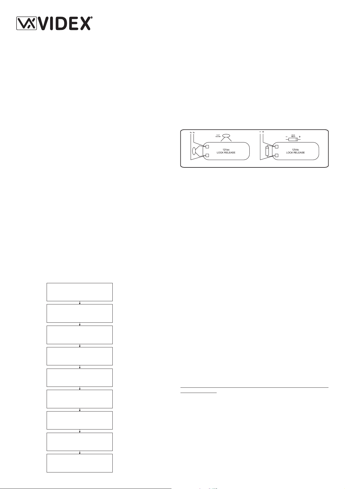
LOCK RELEASE BACKEMF PROTECTION
A capacitor must be fitted across the terminals on AC lock release (Fig.1A) and a
diode must be fitted across the terminals on a DC lock release (Fig.1B) to suppress
back EMF voltages.
Connect the componentsto the lock releases as shownin figures.
BUZZER BACK EMF
When usingintercoms with buzzer call (Art.924/926, SMART1/2, 3101/2, 3001/2and
3021/2) add one0,1uF capacitor between terminals 6 and3.
If help is required for installing or operating this unit please contact our
technical department on +39 0734 631669 (all countries) or +44 0191 224 3174
(UK).
Factory -Office
VIDEX ELECTRONICS S.p.A
Phone: (+39) 0734 - 631669 Fax: (+39) 0734 - 632475 www.videx.it e-mail: info@videx.it
Northern UK Office
VIDEX LTD
Ne6 2XX
Phone: (+44) 0870 3001240 Fax: (+44) 0191 - 2241559 www.videx-security.com
VIDEX
W
W
Fig.1A Fig.1B
. Via del lavoro,1 63020 MONTEGIBERTO (AP) - ITALY
Unit 4-7 Chillingam Industrial Estate Chapman Street NEWCASTLE UPON TYNE
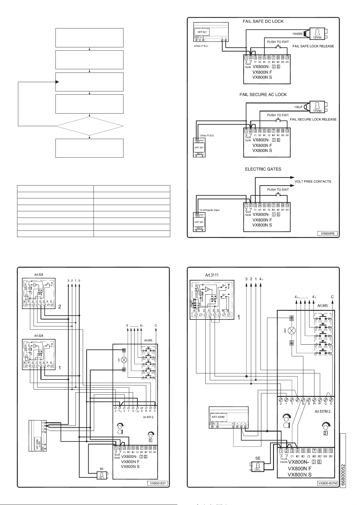
INITIALIZATION
When the installation is concluded and carried out according to the wiring
diagram, power up the system and program it by following the “VX800
PROGRAMMING” Flow Chart.
FIRST TIME SIX TIMES
1 “111111 ” FACTORY
PRESET
TYPE AGAIN SIX TIMES “1” OR
THE NEWENGINEER’S CODE
4 TO 8DIGITS
CODE TO ENABLE
RELAY1
4 TO 8 DIGITS
TWO DIGITS (01TO 99)
I.E. 05=5 SECONDS
00= REMAIN OPEN
CODE TO ENABLE
RELAY2
4 TO 8 DIGITS
TWO DIGITS (01TO 99)
ONLY800-3 VERSION
ONLY800-3 VERSION
RED LED WILLBE OFF
Press Enter
(Red LED will be
ON)
Press Enter
(Melody)
Press Enter
(Melody)
Press Enter
(Melody)
Press Enter
(Melody)
Press Enter
(Melody)
Press Enter
(Melody)
Press Enter
(Melody)
ENTER
“ENGINEER’S CODE”
CONFIRM OR CHANGE
“ENGINEER’S CODE”
ENTER
“ACCESS 1 CODE”
ENTER
“ACCESS 1 TIME”
ENTER
“ACCESS 2 CODE”
ENTER
“ACCESS 2 TIME”
ENTER
“ACCESS 3 CODE”
ENTER
“ACCESS 3 TIME”
SYSTEM READY TO
USE
PROGRAMMING(refer also toflow chart)
>
Enter “ENGINEER’S CODE”: first time type six times “1” (111111 factory
preset) and pressENTER (The red LEDwill illuminate).
Confirm “ENGINEER’S CODE” (typing again the same) or type the new
>
code (4 to 8 digits) then press ENTER (Melody). Pressing twice the
ENTER button without changing the “ENGINEER’S CODE”, will exit
from the programming.
Enter the code to enable “RELAY 1” (ACCESS 1) or re-
>
enter the existing then press ENTER(Melody).
Enter the “RELAY1” operation time (2 digits01 to 99 I.E. 05=5 seconds,
>
(4 to 8 digits)
code
00= remain open time) or re-enter the existing time then press ENTER
(Melody).
Enter the code (4 to 8 digits) to enable “RELAY 2” (ACCESS 2) or re-
>
enter the existingcode then press ENTER(Melody).
Enter the “RELAY2” operation time (2 digits01 to 99 I.E. 05=5 seconds,
>
00= remain open time) or re-enter the existing time then press ENTER
(Melody).
Enter the code (4 to 8 digits) to enable “RELAY 3” (ACCESS 3 only for 3
>
relay models) orre-enter the existing codethen press ENTER (Melody).
Enter the “RELAY3” (only for 3 relay models) operation time (2 digits 01
>
to 99 I.E. 05=5 seconds, 00= remain open time) or re-enter the existing
time then pressENTER (Melody).
The system isready to use (thered LED will beoff).
>
INSTRUCTION TO RETURN SYSTEM TO PRESET ENGINEER’S
FACTORY CODE
Turn off power to codelock.
>
Keep “ENTER” button pressed while turning back on the power to the
>
code lock.
Release “ENTER” button.
>
The master codeis now set atfactory engineer’s code“111111” (six times
>
“1”).
Proceed with programmingfor a new system.
>
NOTES
To switch off any relay while operating, type in the relevant code then
>
press the “CLEAR”button.
To operaterelays together,set the same codefor each relay.
>
If a wrong code is entered, the system will lock out for 5 seconds which
>
will increase each time a wrong code is entered. The systemwill operate
only when thecorrect code is entered.
Page 2
RE-PROGRAMMING GUIDE
ENTER THE
Press Enter
(Red light will
illuminate*)
Press Enter
Press Enter
Press Enter
Repeat steps for
relay 2 and 3
Notes:
* If the red light does not illuminate, the engineer’s code is incorrect. Follow
instructions to return system to preset engineer’s factory code.
** On the first loop of the flow chart its relay 1, second loop is relay 2 and the
third loop is relay 3.
Engineer’s Code
Relay 1 Code
Relay 2 Code
Relay 3 Code
ENGINEER’S CODE
RE-ENTER THE
ENGINEER’S CODE
ENTER ACCESS CODE
ENTER ACCESS TIME
More
YES
DOORS
PRESS ENTER TWICE TO
EXIT PROGRAMMING
?
NO
ALTERNATIVELY ENTER
A NEW ENGINEER’S
CODE (4 TO8DIGITS)
RELAY CODE (4-8 DIGITS)
OPERATE THE DOOR OR
GATE.**
TWO DIGITS (01-99 Sec
OR 00 FOR REMAIN
OPEN)
RED light will
switch OFF
Relay 1 Time
Relay 2 Time
Relay 3 Time
18/12/2006
 Loading...