

Page 1
VX2300 2 Wire Video Digital System
PrtCode:VX2300_3_1.doc – Pag.27 04/09/2012 Rev.3.1
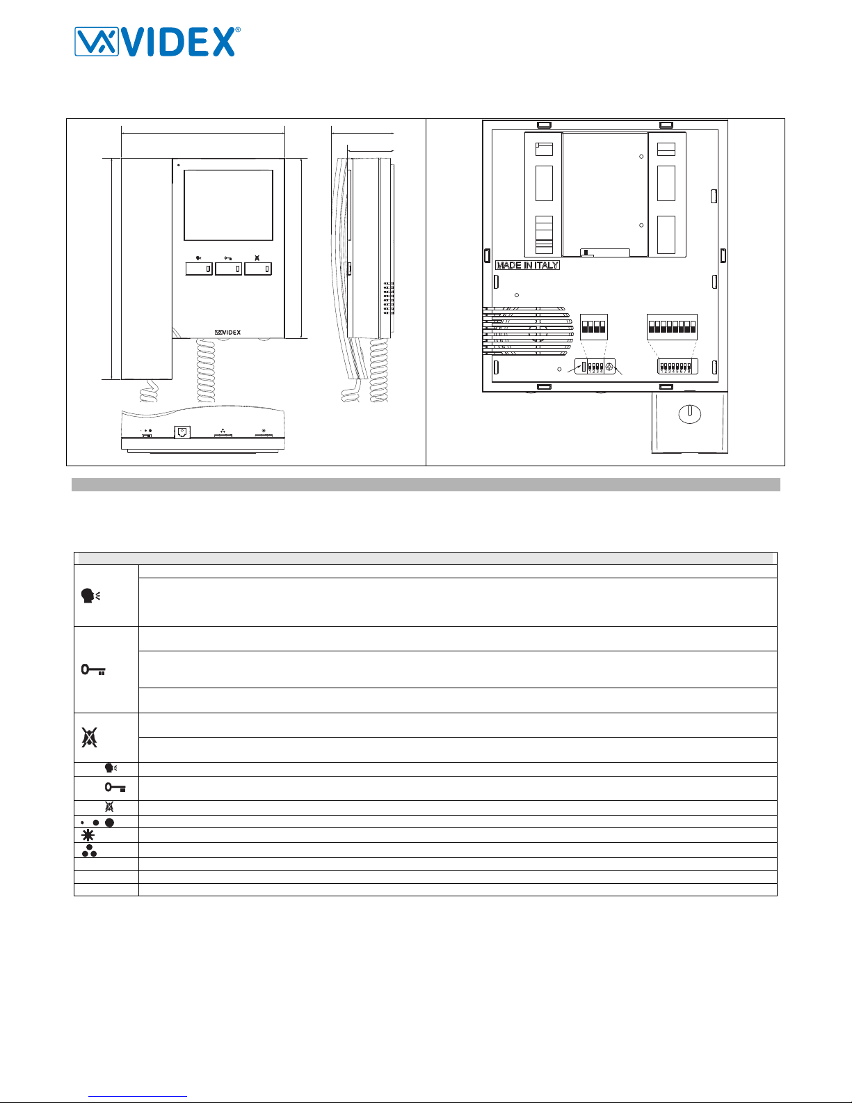
Art.3686
Digital Videophone
161
178
218
62
46
678
1
2
3
5
4
ON
SW1
1
2
3
4
ON
SW3
JP1
SWCH1
TR1
Fig.1 Fig.2
DESCRIPTION
An intelligent Videophone using 3.5” full colour active matrix LCD monitor for VX2300. Including 3 buttons “camera recall”, “dooropen/intercommunicating call”, “privacy/service” plus 3 LED’s* for visual indication of all functions. Adjustments & programmable options: call tone volume on 3 levels (low, medium, high), picture hue, brightness and contrast, call tone melody, number of rings, privacy duration and address. Also includes a local bell function. The Art. 3686 is surface mount and requires the Art. 5980 connection board and wall mounting plate.
PUSH BUTTONS, LEDS AND CONTROLS (FIG.1)
Camera recall push button. Pick up the handset and press as many times as the DEVICE N. of the door station to switch on.
Camera switch push button. If the door station uses the Art.4303N plus the Art.4330N, pressing this button during a conversation
switches the video signal coming from the camera module to the video signal coming from the camera module input for external camera. During the conversation, press and keep pressed the button until the camera switches. Repeat the operation to switch back to
main camera.
Door open push button. Press this button to open the door when you receive a call.
Dry contact relay push button. During a conversation, keep pressed this button for more than 3 seconds to close the dry contacts relay
(terminals “3” and “5” on Art.5980 PCB connection board). The internal link remains closed until the button remains pressed (Max
50Vdc@100mA).
Intercommunication push button. For an intercommunicating call, pick up the handset and press as many times as the extension or
address value to call (see SW3 Intercommunication Settings).
Privacy ON-OFF push button. To enable the function press this button when the videophone is in stand-by. The privacy duration time
can be programmed.
Activate bus relay board Art.2305 push button. To activate a bus relay, during a conversation, press this button quickly as many times
as the address value of the relay.
LED
ON LED. It illuminates when the videophone is switched ON.
LED
Generic use LED. It is supplied from the terminals “6” and “7” of the PCB connection board Art.5980. Normally used to signal th e door
status (open or closed).
LED
PRIVACY ON LED. It illuminates when the privacy service is enabled.
Call tone volume control (3 levels).
Brightness control.
Colour intensity control.
JP1
Jumper for future expansion (must remain closed).
TR1
Contrast control trimmer (rotate left to increase or right to decrease.
SWCH1
Bus termination switch (Left position = BUS termination active, Right position = BUS termination disabled)
Page 2

VX2300 2 Wire Video Digital System
PrtCode:VX2300_3_1.doc – Pag.28 04/09/2012 Rev.3.1
PROGRAMMING
The videophone setup consists of the following settings:
- Number of Rings;
- Melody selection;
- Privacy duration;
- Unit address (1..127, switches 1 to 7 of SW1);
- Bus Termination (open or close, switch SWCH1);
- Intercommunication mode (between apartments or within apartment switch 1 of SW3);
- Extension address (1..4, switches 2,3 of SW3);
- Slave mode (switch 4 of SW3);
The programming of the number of rings, melody and privacy duration are carried out through the videophone push buttons, all other settings are carried out on the two dip-switch banks (SW1 and SW3) on the rear side of the video monitor (all the settings can be done without open the videophone).
Except the number of rings programming, it is necessary to remove temporary the power supply after making any other programming
changes.
NUMBER OF RINGS, MELODY SELECTION AND PRIVACY DURATION
To make these settings, it is necessary to pick up the handset first when the system is in stand-by.
Number of rings
Keep pressed the button “
” until the two LEDs and .are switched on.
Press the “
” button for a number of times corresponding to the required number of rings to set. A beep confirms each time the button is pressed.
Once set the required number of rings, wait approx 5 seconds of idle time that the two LEDs switch off. The new value is stored.
Melody selection
Keep pressed the button “
” until the two LEDs and .are switched on. The unit emits the current selected melody.
Press the “
” button and keep it pressed to listen the next melody. Repeat the operation until the required melody is found.
Once set the required melody is found, wait approx 5 seconds of idle time that the two LEDs switch off. The new melody is set.
Privacy duration
Keep pressed the button “
” until the two LEDs and .are switched on.
Press the “
” button for a number of times corresponding to the required privacy duration to set. Each time the button is pressed, the duration is in-
creased of 15 minutes: to set 2 hours, press the button 8 times.
Once set the required privacy duration, wait approx 5 seconds of idle time that the two LEDs switch off. The new melody is set.
VIDEOPHONE ADDRESS – SW1.1..7
The table above shows how to set the address of the videophone. Considering that ON = 1 and OFF = 0, multiply each
digit for the relevant decimal weight then sum values obtained to get the address: E.g. as highlighted in the table
OFF,ON,OFF,OFF,ON, OFF,ON in binary is equal to 0100101 then multiplying each digit for the relevant decimal weight
you obtain the address that is 37.
Switches Status Binary Code – Decimal Weight
Address
7 6 5 4 3 2 1 64 32 16 8 4 2 1
OFF OFF OFF OFF OFF OFF ON 0 0 0 0 0 0 1 1
OFF OFF OFF OFF OFF ON OFF 0 0 0 0 0 1 0 2
OFF OFF OFF OFF OFF ON ON 0 0 0 0 0 1 1 3
OFF OFF OFF OFF ON OFF OFF 0 0 0 0 1 0 0 4
OFF ON OFF OFF ON OFF ON 0 1 0 0 1 0 1 37
ON ON ON ON ON ON ON 1 1 1 1 1 1 1 127
Note
The maximum number of units allowed is 100 but the address of each unit can be a value between 1 and 127.
VIDEOPHONE ADDRESS – SWCH1
Looking at the videophone from the rear side:
SWCH1
SWCH1
Move the switch to the left position to enable the bus termination Move the switch to the right position to disable the bus termination
In case of more units (intercoms, videophones or video monitors) in a parallel connection (bus wires are connected to the terminals of the first unit then
from this to the second and so on up to 4 units max) the BUS termination must be enabled only for the last unit in the chain while on all other units must
be set to disabled.
INTERCOMMUNICATION MODE – SW3.1
This switch establishes the intercommunication mode: in OFF position (default) intercommunication is between units in the same
apartment (same addresses but different extension); in ON position the intercommunication is between units in different apartments (different addresses).
On installations where there are more than one intercom/videophone in the same apartment and intercommunication between different
apartments is required, only one intercom/videophone may be set wit h this function (SW3.1=ON, SW3.2=OFF, SW3.3=OF F). The other intercom/videophones in the apartment must be set for local intercommunication with extension addresses “2-4” (slaves). From the intercom/videophone set for intercommunication wi th ot her apartm ents it will be not possible to i ntercom munica te wit hin the apartme nt but slave
extensions 2-4 will be able to intercommunicate with each other.
4
3
ON
2
1
=OFF
=ON
ON
SW3.1
SW1.1..7
5
4
3 876
ON
2
1
=OFF
=ON
ON
Page 3

VX2300 2 Wire Video Digital System
PrtCode:VX2300_3_1.doc – Pag.29 04/09/2012 Rev.3.1
EXTENSION NO – SW3.2..3
If the intercommunication between apartments is enabled (switch 1 of SW3 = ON) leave these two switches in default position (both to OFF). Otherwise,
if the intercommunication is between the same apartment (switch 1 of SW3 = OFF), set the extension addresses starting always from 1. During the external call, all video monitors in the same flat will ring but the video will be shown only from the videmononitor with extension address 1.
2 3 Extension No.
OFF OFF 1 (default, master)
ON OFF 2 (slave)
OFF ON 3 (slave)
ON ON 4 (slave)
4
3
ON
2
1
=OFF
=ON
ON
SW3.2..3
SLAVE MODE - SW3.4
This set up concerns the answering mode of the video monitor when there is more than one unit (max 4) in the same apartment.
OFF (default) = during a call, only the video monitor with extension 1 (master) will show the video. ON = the video monitor will be
switched on independently of the extension address: in this case the video monitor must be supplied locally using a power supply Art.2321 and connecting respectively BUS+ to terminal 14 and BUS- to terminal 11 of the pcb connection board provided
with the Art.5980 (the local power supply is required for each black & white slave videophone or starting from the third slave vid-
eophone when are used all colour videophones). If you set ON this switch for one slave video phone, you must set ON t he same switch also for
the relevant master videophone.
VIDEOMONITOR CONNECTION BOARD ART.5980
SIGNAL ON CONNECTION TERMINALS
Terminal Signal Description
1 GND
Ground
2 BUS1
Bus input
3 C
Dry contacts relay common contact (during a conversation, keep pressed the button
for more than 3 seconds to
enable the internal link between terminals “3” and “5” – the link remains until the button remains pressed) Max 50Vdc @
100mA
4 BUS2
Bus input
5 NO
Dry contacts relay common contact (during a conversation, keep pressed the button
for more than 3 seconds to
enable the internal link between terminals “3” and “5” – the link remains until the button remains pressed) Max 50Vdc @
100mA
6 DOL
Auxiliary LED power supply input (+12Vdc)
7 DOL
Auxiliary LED power supply input (ground)
8 GND
Ground
9 GND
Ground
10 LB
Local bell input (active low)
11 GND
Ground
12
13
14 +VAUX
Auxiliary power supply input (to be used when the switch 4 of SW3 is set to ON)
15
16
17
18 AL
Alarm input (not implemented yet)
19
AL-LB_GND
Ground output for use in combination with “AL” & “LB” active low inputs
20
4
3
ON
2
1
=OFF
=ON
ON
SW3.4
Page 4

VX2300 2 Wire Video Digital System
PrtCode:VX2300_3_1.doc – Pag.30 04/09/2012 Rev.3.1
VIDEOMONITOR WALL MOUNTING INSTRUCTIONS
135cm
Fig.1
a
a
a
b
c
c
f
f
f
f
g
e
d
b
b
b
a
Fig.2
A
B
h
i
l
m
m
m
m
c
Fig.3
n
Fig.4
Cables must be fed through the opening “e ” (Fig. 2A) of the mountin g plate “c ”, which should be fitted approximately 135cm from finished floor level
as shown in Fig 1;
Place the mounting plate “c ” against the wall feeding the wire group “d” through opening “e” of the mounting plate and mark the fixing holes “a ”
(Fig. 2A)
Drill the fixing holes “a”, insert the wall plugs “b” then with the cables threaded through opening “e” fix the mounting plate “c” to the wall with the 4
screws provided “f” (Fig. 2A).
Hook the pcb connection board “g ” to the mounting plate “c ”as shown in Fig2B and connect the wire s (using the screwdriver provided) to the t ermi-
nals as shown in the diagram provided;
Once the wires are connected, hook the videophone “h” to the Mounting plate “c” as shown in Fig. 3.
o Connect the Plug “I” on the ribbon cable from the videophone to the plug “l” on the PCB connection board “g”;
o Place the videophone “h” against the 4 hooks “m” on the mounting plate “c” (in line with the 4 openings “n” on the rear side of the video-
phone Fig. 4) and push down as suggested by the pointers in Fig. 3, the videophone will lock into place;
To remove the videophone, hold it firmly and push the unit in an upward direction until the videophone “h” unlocks from the mounting plate “c”
SPECIFICATION
Housing/Mounting
3600 Series Videophones / mounting plate plus connection board
Push buttons
Yes, 3
Programming
Yes, carried out by the buttons and the dip-switches located on the rear of the videophone
Controls
Call tone volume, brightness and hue
Power Supply
Supplied by the BUS line
Working Temperature
-10 +50 ºC
CUSTOMER SUPPORT INFORMATION
All Countries Customers UK Customers
VIDEX Electronics S.p.A.
www.videx.it – technical@videx.it
Tel.+39 0734 631669
Fax +39 0734 632475
VIDEX Security LTD
www.videx-security.com
Tech Line 0191 224 3174
Fax 0191 224 1559
The product is CE marked demonstrating its conformity and is for distribution within all
member states of the EU with no restrictions.
This product follows the provisions of the European Directives
89/336/EEC & 92/31/EEC (EMC),
73/23/EEC (LVD) and 93/68/EEC (CE marking).
Il prodotto è marchiato CE a dimostrazione della sua conformità e può essere distribuito liberamente all’interno dei paesi membri dell’unione europea EU.
Questo prodotto è conforme alle direttive Europee
89/336/EEC & 92/31/EEC (EMC),
73/23/EEC (LVD) e 93/68/EEC (Marcatura CE).
 Loading...