

Page 1
TECHNICAL MANUAL
EDITION 1.0
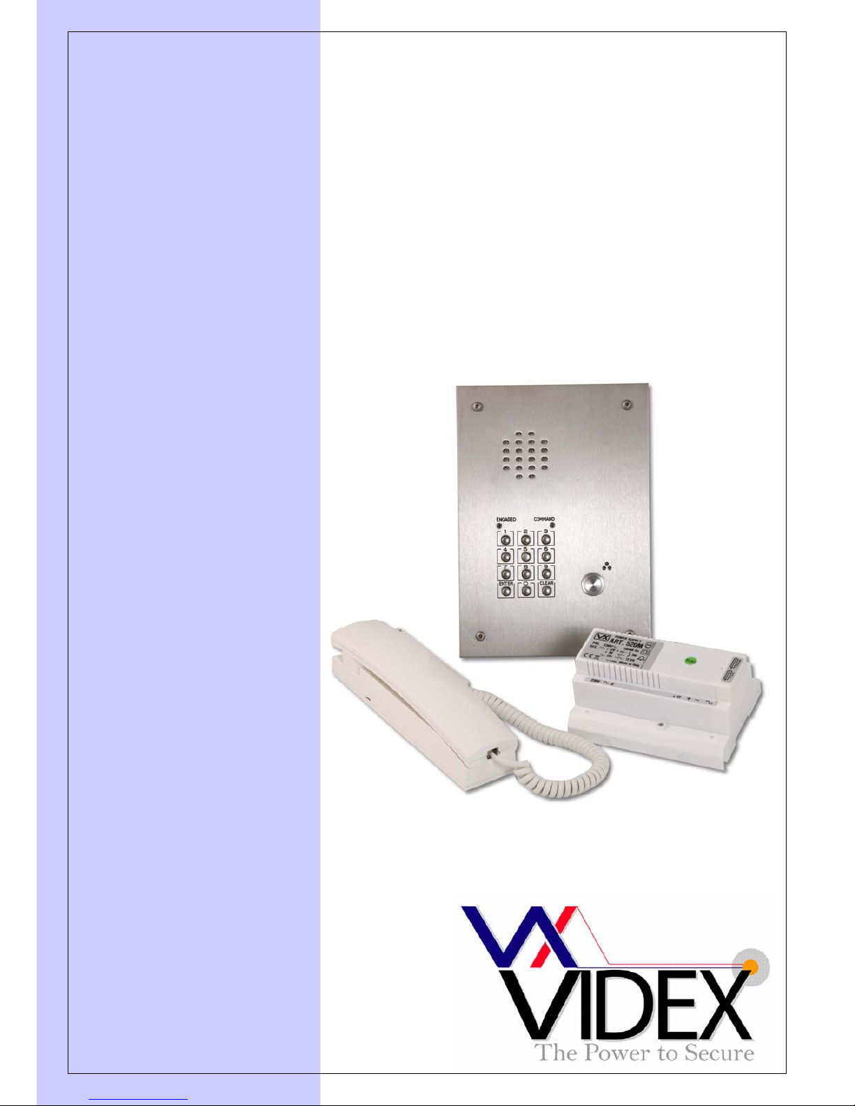
VANDAL RESISTANT
ONE BUTTON + CODED
ACCESS DOOR ENTRY
KIT
VRDK1/CL (25H/CL)
Page 2

PAGE 2 of 12 VRDK1/CL TECHNICAL MANUAL VER1.0
Page 3
PAGE 3 of 12 VRDK1/CL TECHNICAL MANUAL VER1.0
MANUAL INTRODUCTION
The information in this manual is intended as an installation and commissioning guide for
the vandal resistant one button audio intercom kit. This manual should be read carefully
before the installation commences. Any damage caused to the equipment due to faulty
installations where the information in this manual has not been followed is not the
responsibility of Videx Security Ltd.
VIDEX run free training courses for engineers who are not familiar with the Videx product
range. Technical help is also available on 0191 224 3174 during office hours or via e-mail
tech@videx-security.com.
SYSTEM INTRODUCTION
This kit will enable a caller at an entrance point to signal an occupant in the dwelling by
pressing a call button which will buzz an audio telephone inside. A two way conversation
can take place once the telephone is answered and then if required, the occupant can
release an electric lock release by pressing a button on the telephone. Additionally users
can gain access using an access code. The kit does not include the electric lock release. A
12V AC release should be used with this kit.
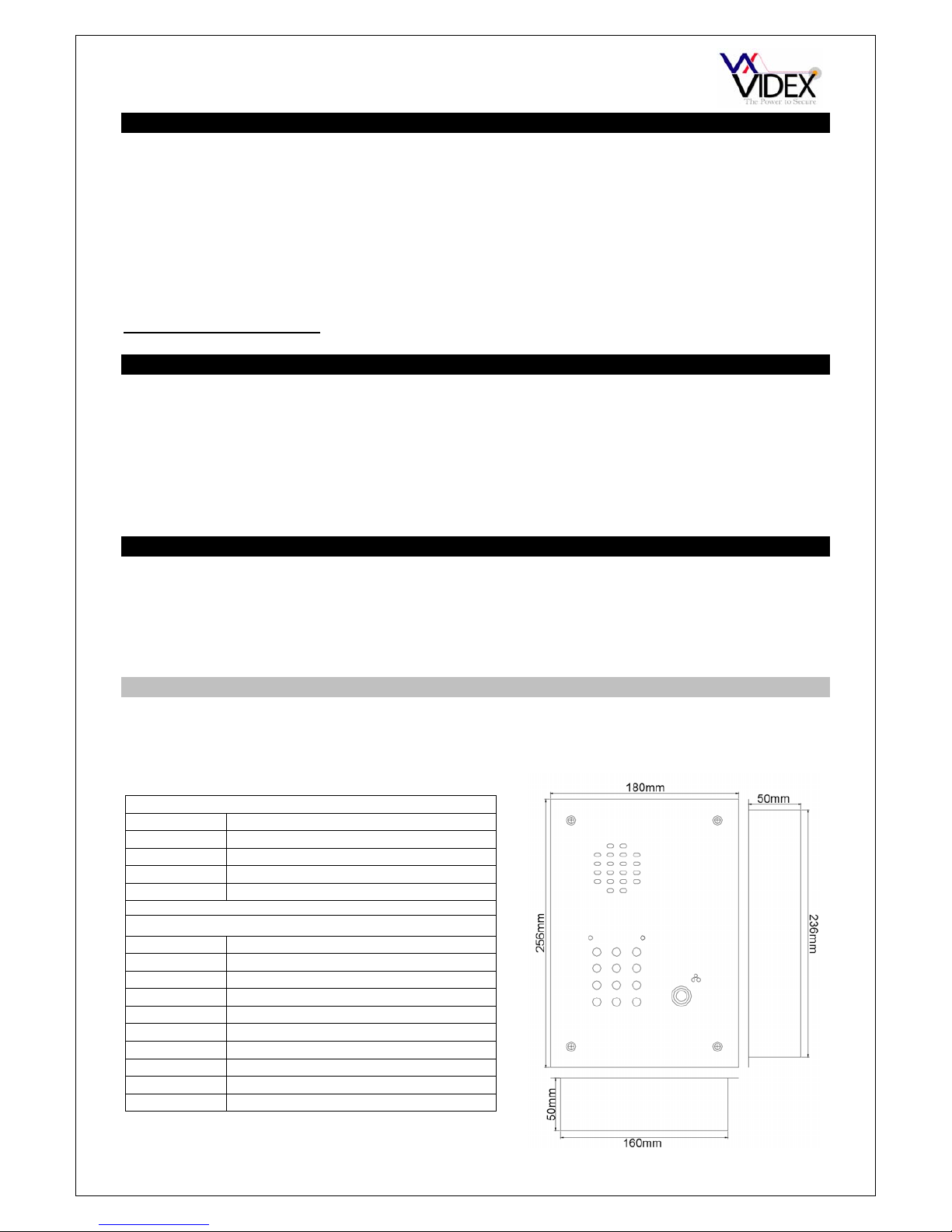
SYSTEM COMPONENTS
This kit comprises of a flush vandal resistant door panel with coded access, audio
telephone and PSU. The door panel can be converted to surface by ordering the VR/S2
surface back box. Up to a maximum of three telephones can be used on the system to call
in parallel.
DOOR PANEL
The vandal resistant door panel will consist of an amplifier module, codelock module,
button, vandal resistant plate and back box.
Amplifier module (Art.437 or Art.537)
Connection Function
1 Receive speech from apartment
2 Transmit speech to apartment
3 +8Vdc to +12Vdc input
4 0V (Ground)
Codelock module connections (VX800N)
1 12V power input from PSU
2 Ground 0V from PSU
3 Common connection on relay 1
4 Normally open connection on relay 1
5 Normally closed connection on relay 1
6 Common connection on relay 2
7 Normally open connection on relay 2
8 Normally closed connection on relay 2
9 Push to exit input triggering relay 2
10 Push to exit input triggering relay 1
Page 4
PAGE 4 of 12 VRDK1/CL TECHNICAL MANUAL VER1.0
Speech volume adjustments are carried out at the door panel using a small trimmer driver.
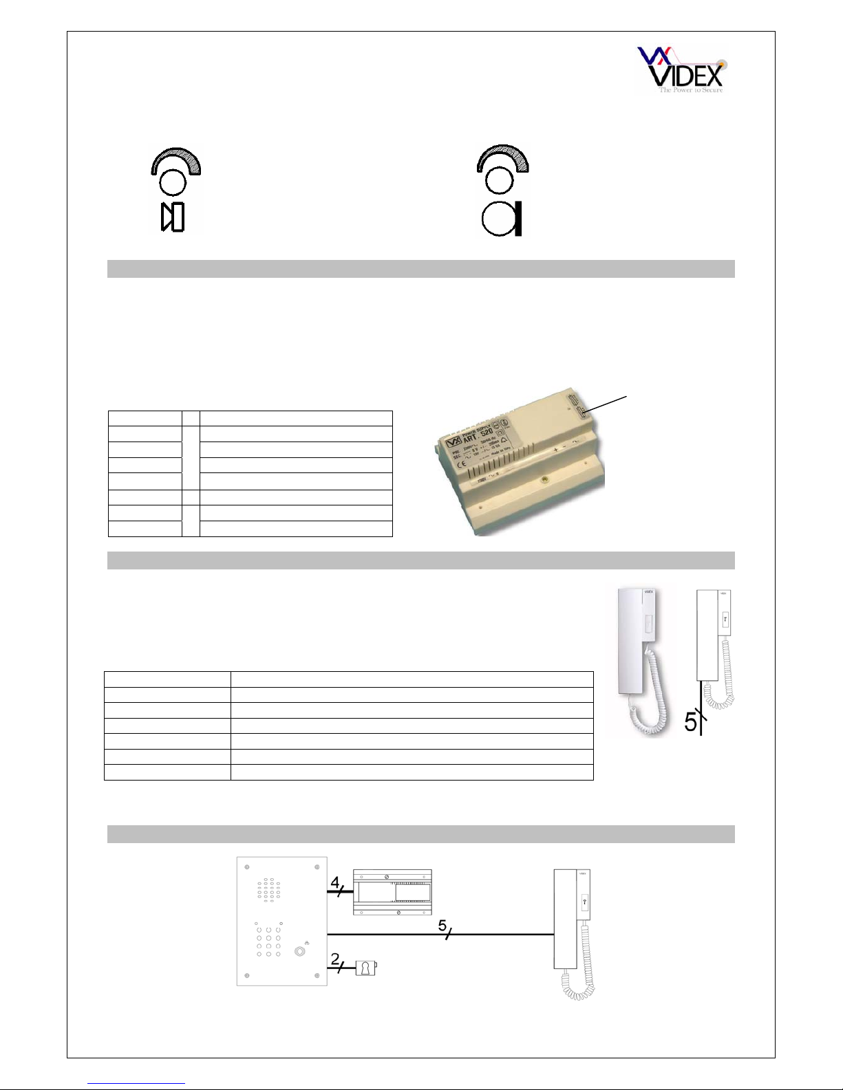
POWER SUPPLY
Art.520M
The power supply is the Art.520M. Outputs of 12Vdc (200mA), 8Vdc (300mA) and 13Vac
(1A) are available. The dc outputs are designed to power the amplifier modules only and
can not be used to power other devices such as lock releases etc. These items must be
connected to the AC output of this power supply.
.
TELEPHONE
Art.3021
BLOCK DIAGRAM
CONNECTIONS
Terminal Function
+12 12Vdc output (200mA Max.)
+8 8Vdc output (300mA Max.)
- 0V (Ground)
~
13Vac (1A Max.)
230 Mains in (Live connection)
0 Mains in (Neutral connection)
The Smart line Art.3021 is a wall mountable AC buzzer phone and
includes a lock release push button.
CONNECTIONS:-
Function
1 Transmit speech to the door panel
2 Receive speech from the door panel
3 0V
4 Not used (Electronic call tone input)
5 Lock trigger (Switched 0V)
6 Call line (13Vac input to trigger buzzer)
Adjustment for
speech volume level
at the door station
Adjustment for
speech volume at the
apartment
Fuse
compartment
Page 5

PAGE 5 of 12 VRDK1/CL TECHNICAL MANUAL VER1.0
INSTALLATION
The wiring diagram towards the back of this manual should be followed carefully. Heavy
duty conductors on wiring diagrams are shown heavily outlined, These wires should be
doubled up.
- Check that all components are free from damage before installing (Do not proceed with
installation in the event of damage).
- Keep all packaging away from children.
- Do not obstruct the ventilation openings or slots on any of the devices.
- All connections to mains voltages must be made to the current national standards (IEE
Wiring regulations)
- Install an appropriate fused spur or isolation switch to isolate the mains.
- Isolate the mains before carrying out any maintenance work on the system.
- All intercom and access control cables must be routed separately from the mains.
Lock release and AC buzzer back EMF protection : A capacitor must be fitted across
the terminals on an AC lock release and the AC buzzer inside the telephone. When using
a DC lock release with a separate DC PSU a diode must be fitted across the terminals of
the lock release as shown in the diagrams below to suppress back EMF voltages.
LOCK RELEASE
12V AC
~~
0.1uF capacitor
+
-
1N4002
+
-
12V DC
LOCK RELEASE
DIODE
Safety Note : An earth connection should also be fitted to the door panel stainless steel
facia using one of the studs provided.
Page 6

PAGE 6 of 12 VRDK1/CL TECHNICAL MANUAL VER1.0
CABLE SIZE GUIDE
AUDIO SYSTEM
Connections from door panel to telephone.
Connections 50m 100m 200m 300m 400m
1
0.25mm² 0.35mm² 0.5mm² 0.75mm² 1.0mm²
2
0.25mm² 0.35mm² 0.5mm² 0.75mm² 1.0mm²
3
0.25mm² 0.35mm² 0.5mm² 0.75mm² 1.0mm²
5
0.25mm² 0.35mm² 0.5mm² 0.75mm² 1.0mm²
6
0.25mm² 0.35mm² 0.5mm² 0.75mm² 1.0mm²
When ever possible connection 1(Tx) should be twisted with connection 3(Gnd) and connection 2(Rx) should
be twisted with connection 3(Gnd) as pairs.
Maximum acceptable resistance for terminals = 10Ω
Connections for power supply output to door panel and lock release connections. These
connections are shown heavily outlined on the wiring diagram.
50m 100m
Connections
0.5mm² 0.75mm²
The power supply should be located as close to the door panel as possible for best performance.
Maximum acceptable resistance for above cables = 3Ω
TESTING THE INSTALLATION
- Check all the connections have been made correctly and then power up the system.
- Call the apartment. Check for call to the apartment, speech in both directions and lock
release.
- If the volume of speech needs to be adjusted, this can be done by adjusting the presets
on the rear of the amplifier at the door panel.
PANEL CARE
The door panels are manufactured from either 12 Gauge 304 grade stainless steel or
mirror finished brass. It is important that the facia is cleaned on regular occasions to
prevent dirt build up and tarnishing of the metal. A general household metal polish can be
used but care should be taken to follow the grain of the metal when polishing and also
avoid any polish build up around the call button which may prevent the button from
operating correctly.
Page 7

PAGE 7 of 12 VRDK1/CL TECHNICAL MANUAL VER1.0
ACCESSORIES CONNECTION GUIDE
3021
Page 8

PAGE 8 of 12 VRDK1/CL TECHNICAL MANUAL VER1.0
WIRING DIAGRAM
Page 9

PAGE 9 of 12 VRDK1/CL TECHNICAL MANUAL VER1.0
VX800N CODELOCK
The VX800N includes two relays (5A contacts), two push to exit inputs (Switched negative)
and can have up to two 4 to 8 digit access codes programmed (One per relay). The relay
times can be programmed from 01 second up to 99 seconds or by setting the relay time to
00, latch the relay(To latch, enter the code followed by enter and to unlatch enter the code
followed by clear).
INITIAL PROGRAMMING
All programming is carried out using the codelock keypad. The programming menu is
protected by an engineer’s code. The factory default engineers code is 111111 (6x1). This
code can be changed to any four to six digit code during the program but must be different
to the codes used to gain entry. Follow the flow chart to setup the system:-
Enter the master code.
111111
Then press enter
The red LED will illuminate to acknowledge programming mode. If the red
LED does not illuminate check the master code is correct. If the master
code may have been changed from the factory default and you do not
know what it is then follow the factory default procedure on the following
page.
Enter a new engineers
code or enter the same
engineers code again
followed b
y
enter
This code can be from 4 – 8 digits and will not activate a relay. It can only
be used to enter programming mode.
Note this new code in the box provided on the next page. It will be needed
to re-program the codes in the future.
Enter the access code
for relay 1 and then
press enter
This code will be used to open the door/gate (Relay 1). The code can be
from 4 – 8 digits long and must be different from the engineer’s code.
Enter a two digit relay 1
time from 00 – 99 and
then press enter
This is the time the relay 1 will energise for. 00 will latch the relay when
the code is entered and require the code followed by clear to unlatch.
Enter the access code
for relay 2 and then
press enter
This code will be used to open the door/gate (Relay 2). The code can be
from 4 – 8 digits long and must be different from the engineer’s code.
Enter a two digit relay 2
time from 00 – 99 and
then press enter
This is the time the relay 2 will energise for. 00 will latch the relay when
the code is entered and require the code followed by clear to unlatch.
More
codes?
YES
NO
Press enter twice
The red LED will go off to confirm the exit from programming mode.
Page 10

PAGE 10 of 12 VRDK1/CL TECHNICAL MANUAL VER1.0
VX800N CODELOCK REPROGRAMMING GUIDE
Enter the
engineer’s
code
Press Enter
RED Light will
illuminate *
Notes:
* If the red light does not illuminate, the engineers code is incorrect. Follow the factory default procedure below.
** On the first loop of the flow chart its relay 1, second loop is relay 2.
FACTORY DEFAULT PROCEDURE
Step 1 Remove the power from the keypad
Step 2 Press and hold the enter button while re-powering the keypad
Step 3 Release the enter button. The factory engineer’s code is restored to 111111 (6 x 1)
Re-Enter the
engineer’s
code
Alternatively enter a
new engineer’s
code (4-8 digits)
Press Enter
Enter relay
code
Relay code (4 – 8
digits) operates the
door or gate. **
Press Enter
Enter relay
time
Press Enter
Two digits (01 – 99 Sec
or 00 for remain open)
More
doors?
NO
Press Enter
twice to exit
prog
rammin
g
RED Light will
switch off
Repeat steps
for relay 2
YES
Engineers code
Relay 1 code
Relay 2 code
Relay 1 Time
Relay 2 Time
Page 11

PAGE 11 of 12 VRDK1/CL TECHNICAL MANUAL VER1.0
TROUBLE SHOOTING
SYMPTOM TEST
No speech from the door panel to the
telephone.
Check terminal 2 on the amplifier for continuity to
terminal 2 on the telephone.
Before lifting the handset, check the voltage to
terminal 2 of the amplifier is 8-12Vdc. Trace this
voltage to terminal 2 to the telephone.
Check the voltage drops to approx. 1Vdc after the
handset is lifted. (If not try another telephone)
If all else fails try another amplifier at the door station
No speech from the telephone to the door
panel.
Check terminal 1 on the door panel amplifier for
continuity back to terminal 1 on the telephone.
Before lifting the handset, check the voltage to on
terminal 1 of the amplifier is 8-12Vdc. Trace this
voltage to terminal 1 to the telephone.
Check the voltage drops to approx. 4Vdc after the
handset is lifted. (If not try another telephone)
If all else fails try another amplifier at the door station
No speech in either direction
Check the 315mA fuse in the power supply
Check for 8-12Vdc across terminals 3 & 4 on the
door panel amplifier. This should be there all the time
and comes directly from the PSU.
Lock will not operate from telephone
Check terminal 5 on the telephone. This terminal
shorts to terminal 3 of the telephone when pressed
(Becomes 0V).
Check terminal 5 of the telephone is connected
correctly to terminal 10 of the keypad. Try touching a
wire across terminal 10 & terminal 2 on the keypad
to ensure the codelock is operating the relay.
If a push to exit is also connected to terminal 10 of
the codelock ensure it is not a normally closed switch
or in short.
Nothing happens when any call button is
pressed
Check the common of the buttons has 13Vac
present at all times.
When a call button is pressed you should be able to
read 13Vac on terminals 3 & 6 of the telephone (6 of
the telephone comes direct from the call button). If
voltage is there then check/change the buzzer.
Hum on the speech lines
Ensure all intercom cables do not run close to higher
voltage cables
Try another amplifier at the door panel.
Codelock not operating Check power on terminals 1 & 2 on the codelock is
12V. If this voltage is lower it may not operate the
relays correctly.
Check the keys beep when pressed. This will not
happen if the codelock is faulty or has the incorrect
power connected to terminals 1 & 2
Try re-programming the codelock
Page 12

PAGE 12 of 12 VRDK1/CL TECHNICAL MANUAL VER1.0
Northern Office
Videx Security Ltd
Unit 4-7 Chillingham Ind. Est.
Newcastle Upon Tyne
NE6 2XX
TEL 0870 300 1240
FAX 0191 224 5678
Southern Office
1 Osprey
Trinity Park
Trinity Way
London
E4 8TD
FAX 0208 523 5825
TECHNICAL SUPPORT
tech@videx-security.com
TEL 0191 224 3174
FAX 0191 224 4938
http://www.videx-security.com
 Loading...