

Page 1
VR GSM AUDIO INTERCOM KIT
4000 Series Vandal Resistant GSM Audio Intercom
with Proximity Facility
66250675-EN
V1.0 - 05/09/17
We recommend
This equipment is installed by a
Competent Electrician, Security or
Communications Engineer.
Technical Manual
ENG
GSMVRK
GSMVRKC
Page 2
66250675-EN - V1.0 - 05/09/17
THE POWER TO SECURE
2
4000 Series Vandal Resistant GSM - Technical Manual
4000 Series Vandal Resistant GSM Audio Intercom with Proximity Facility
EU RoHS DECLARATION OF CONFORMITY
Telit Communications certies that the GL865-QUAD V3 (Quad Band GSM850/EGSM900/DCS1800/PCS1900 GPRS Wireless
Module) is in conformity with Directive 2011/65/EU of the European Parliament and the Council of 8th June 2011 on the
restriction of the use of certain hazardous substances in electrical and electronic equipment. The conformity with the applicable
requirements of the Directive 2011/65/EU has been demonstrated against the following harmonized standard: EN 50581:2012
Technical Documentation for the assessment of electrical and electronic products with respect to the restriction of hazardous
substances.
WARNING!
To comply with FCC RF exposure requirements, a separation distance of 20cm (7.87”) or more
must be maintained between the antenna of this product and all persons.
Separate FCC approval for this product is not required as it will be classed as a xed installation.
THIS PRODUCT IS NOT DESIGNED TO BE USED AS AN EMERGENCY CALL POINT.
MANUFACTURER
All Countries:
VIDEX ELECTRONICS S.P.A.
www.videx.it - technical@videx.it
Tel: +39 0734-631699 - Fax: +39 0734-632475
The product is CE marked demonstrating its conformity and is for distribution
within all member states of the EU with no restrictions. This product follows
the provisions of the European Directives 2014/30/EU (EMC); 2014/35/EU
(LVD); 2011/65/EU (RoHS): CE marking 93/68/EEC.
UK Customers:
VIDEX SECURITY LTD.
www.videxuk.com - tech@videxuk.com
Tech Line: 0191 224 3174 - Fax: 0191 224 1559
CUSTOMER SUPPORT
VIDEX ELECTRONICS S.P.A.
Via del Lavoro, 1 - 63846 Monte Gilberto (FM) Italy
Tel: (+39) 0734-631699 - Fax: (+39) 0734-632475
www.videx.it - info@videx.it
Declaration of Conformity
Page 3
66250675-EN - V1.0 - 05/09/17
3
4000 Series Vandal Resistant GSM - Technical Manual
4000 Series Vandal Resistant GSM Audio Intercom with Proximity Facility
Contents
Introduction .......................................................................................................................................................................................4
System Components and Available Versions ..................................................................................................................................6
Technical Information .................................................................................................................................................................... 13
Additional Modules ........................................................................................................................................................................ 19
Wiring Diagrams ............................................................................................................................................................................. 23
Auxiliary Input & Output ............................................................................................................................................................... 26
USB Connection .............................................................................................................................................................................. 28
General Directions for Installation ................................................................................................................................................ 29
Fitting the SIM & Connecting Power ............................................................................................................................................. 32
Reset Procedure .............................................................................................................................................................................. 33
4000 Series Back Box Installation ................................................................................................................................................. 34
Programming the GSM Intercom .................................................................................................................................................. 38
System Operation ........................................................................................................................................................................... 49
User Commands .............................................................................................................................................................................. 51
Additional User Information .......................................................................................................................................................... 52
User Management .......................................................................................................................................................................... 54
Troubleshooting ............................................................................................................................................................................. 55
General Information ....................................................................................................................................................................... 57
Notes ................................................................................................................................................................................................ 58
Page 4
66250675-EN - V1.0 - 05/09/17
4
4000 Series Vandal Resistant GSM - Technical Manual
4000 Series Vandal Resistant GSM Audio Intercom with Proximity Facility
Introduction
MANUAL INTRODUCTION
The information in this manual is intended as an installation and commissioning guide for the 4000 series vandal resistant GSM audio
intercom system. This manual should be read carefully before the installation commences. Any damage caused to the equipment due
to faulty installation where the information in this manual has not been followed is not the responsibility of Videx Security Ltd.
It is recommended that the vandal resistant GSM audio intercom is installed by a competent electrician, security or communications
engineer.
For UK customers Videx run free training courses for engineers who are unfamilier or who have not installed this system before. Technical
help is also available on tel: 0191 224 3174 during oce hours (8:30am - 5:00pm MON to FRI) or via e-mail: tech@videxuk.com.
A copy of this Technical Manual can also be downloaded from the Videx website: www.videxuk.com, www.videx.it.
SYSTEM INTRODUCTION
The 4000 series vandal resistant GSM is designed to work on the same technology as mobile phones. It enables a call to be made
from an entry point (door, gate etc), to any telephone number (mobile or land line). Up to 24 users can be programmed into the
door panel, each able to call up to four telephone numbers (if the primary number is busy or not answered, the call can be diverted
through to up to three dierent divert numbers). The standard vandal resistant GSM works on a 2G network. A 3G variant is also
available (sux /3G to the part number e.g. Art.VR4KGSM-0/3G, Art.VR4KGSM-1/3G etc.).
Key features of the system include:
• Vandal resistant brushed stainless steel (2.5mm thick) front panel for the 4000 series range.
• Call progress LED indication.
• Dial to Open facility (this feature enables up to 1000 stored numbers to dial the GSM intercom, the intercom panel will not
answer these calls, but will activate the door/gate relay without being charged for the call).
• Micro-USB connection (for ease of programming using the GSMSK PC software).
• Wiegand proximity connection feature (allows connection of a Wiegand proximity reader to store up to 1000 fobs/cards,
these cards when presented to the reader will activate the door/gate).
• VR4KDM (UIM138/MODULE) interface connection for additional call progress indication and voice annunciation.
• A dry contact relay.
• A switched 0V auxiliary input (AI).
• An open collector auxiliary output (AO).
• Push to exit input.
• 24 programmable buttons (each with 4 numbers, 1 primary and 3 diverts).
• Programmable timeband facility.
• Integrated bootloader function (for updating the GSM intercom rmware via the GSMSK PC software).
• Event logging system (which can record up to 4000 events).
Programming of the telephone numbers and the additional features, including programming key fobs/cards for the Wiegand
proximity access, can be carried out via text messaging (refer to pages 38 to 48) or PC using the GSMSK PC software (refer to the
GSMSK PC software manual).
SIM CARD SELECTION
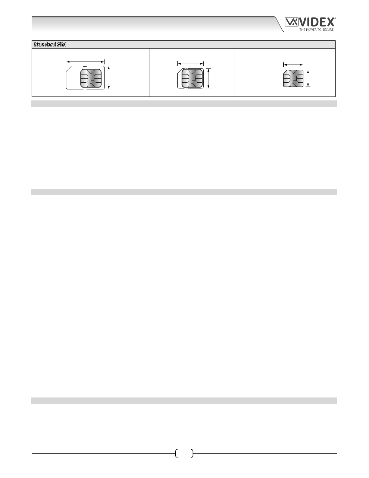
A SIM card is required for this product but not supplied by Videx. The GSM intercom can only accept a standard size SIM card
(refer to the following SIM card size chart on page 5), both a micro-SIM and nano-SIM are not suitable. It is recommended to choose
the SIM card which has the best coverage for the area in which the intercom panel will be installed. Both contract and ‘Pay as
you go’ SIM cards can be used, however if using a ‘Pay as you go’ we would recommend setting up an automatic top up to avoid
running short on credit and losing the use of the intercom panel. Alternatively if you already have a contract mobile phone it should
be possible to get a second SIM card and telephone number on the existing account. For more information contact the SIM card
provider or visit their web sites.
Page 5
66250675-EN - V1.0 - 05/09/17
5
4000 Series Vandal Resistant GSM - Technical Manual
4000 Series Vandal Resistant GSM Audio Intercom with Proximity Facility
Standard SIM Micro-SIM Nano-SIM
;
25mm
15mm
:
15mm
12mm
:
12.3mm
8.8mm
NETWORK PROVIDER SELECTION
It is imperative that for the reliable operation of the system that the best network provider for the area is selected. Problems such as
network disconnection can occur if the provider has signal or interference problems for that area. We would recommend using a GSM
signal strength meter (not supplied by Videx) to survey the intended antenna location. Contact Videx for more information on where
to purchase a tester.
For UK customers, as an initial check we also recommend visiting the ofcom website www.ofcom.org.uk and follow the onsite links to
their online mobile coverage tool. This tool will advise on the best coverage for the main network providers and other general queries
that you may have about the service provider.
For customers from other countries we suggest consulting the website of the network provider that will be used to check the coverage.
The antenna should always be mounted vertically at the highest point possible. Metal structures and sources of interference such as
power cables, control panels etc. can aect signals and so the antenna should be mounted away from these.
PRECAUTIONARY ADVICE
• When mounting the GSM antenna, choose a location which is away from human interaction and away from the intercom panel.
Route the GSM antenna cable from the intercom panel so that it is separate from the power supply cables and microphone wire.
• Always ensure the power is switched OFF to the intercom panel before inserting or removing the SIM card.
• New SIM cards will need registering with the network service provider before they can be used. Full details of how this is done
can normally be found in the SIM card pack. It will normally require that the SIM card is inserted into a mobile phone, a number
dialled and instructions followed. While the SIM is in the mobile phone it would be a good time to disable any PIN codes, call
diverts, ring back and disable features such as voicemail and text alerts. Details of how to do this can be found on the SIM card
provider’s web site or by calling their customer services. Recommended SIM card providers are: Vodafone, T-Mobile, O2 or
Orange/EE. The 3 network can only be used on our 3G devices (Art.VR4KGSM-1/3G etc.), also refer to page 6.
• To be able to receive text messages from the intercom panel, the SIM card will require an SMS service centre number. This is
normally preinstalled on new SIM cards but if you are having trouble receiving SMS messages you will need to conrm this by
inserting the SIM card into a mobile phone and using the phones menu options to check it. If a number is not programmed then
it should be programmed while in the phone (the number can be obtained from the network service provider).
• Voicemail and text alerts must be switched OFF on the SIM card when using the dial in to release the door/gate feature. For
Vodafone and O2 this can be done while the SIM card is in the intercom panel. For Orange/EE, T-Mobile and other providers the
SIM card must be removed from the intercom panel, inserted into a mobile phone and the mobile phone menu instructions
followed.
• When storing the intercom panel’s telephone number in your own mobile phone avoid using an obvious name such as ‘Front
Door, or ‘My Gate’ as this would make it easy to decipher if your phone was lost or stolen.
• The PIN request feature must be disabled on the SIM card before using it in the Intercom panel. It is likely on a new SIM card that
it will not be enabled but if it is, it will prevent the system from working at all.
• This product may not be suitable for installation in hospitals, health care facilities or in the presence of ammable gases or
liquids. Seek advice and authorisation before installing this product in these locations. This product is not designed to be used
as an emergency call point.
Network provider and services conguration codes mentioned in this manual are specic for the UK. For overseas customers please contact
the network provider of your country for the corresponding codes.
IMPORTANT NOTE ABOUT THE SIM
When using a pay monthly SIM card you must ask the service provider to put a spend limit (credit limit) on the account (Vodafone
call this service ‘spend checker’). This is to safeguard against possible problems which could result in a large phone bill at the end of
the month. All providers oer this service. You will need to either ring them or e-mail them to set this up. Automatic top ups should
also have a monthly limit. We would suggest a limit of £50.00 which should be more than enough. This service is not provided by
Videx.
Introduction
Page 6
66250675-EN - V1.0 - 05/09/17
6
4000 Series Vandal Resistant GSM Audio Intercom with Proximity Facility
4000 Series Vandal Resistant GSM - Technical Manual
DESCRIPTION
A system comprises of an intercom panel, power supply, SIM card (SIM card not provided by Videx) and antenna. The intercom panel
is part of the Videx 4000 series vandal resistant modular design allowing it to be customised to the installation requirements for
example including coded access or including the correct number of call buttons (up to 24 call buttons).
ART. VR4KGSM ART. 150 INTERCOM AVAILABLE VERSIONS
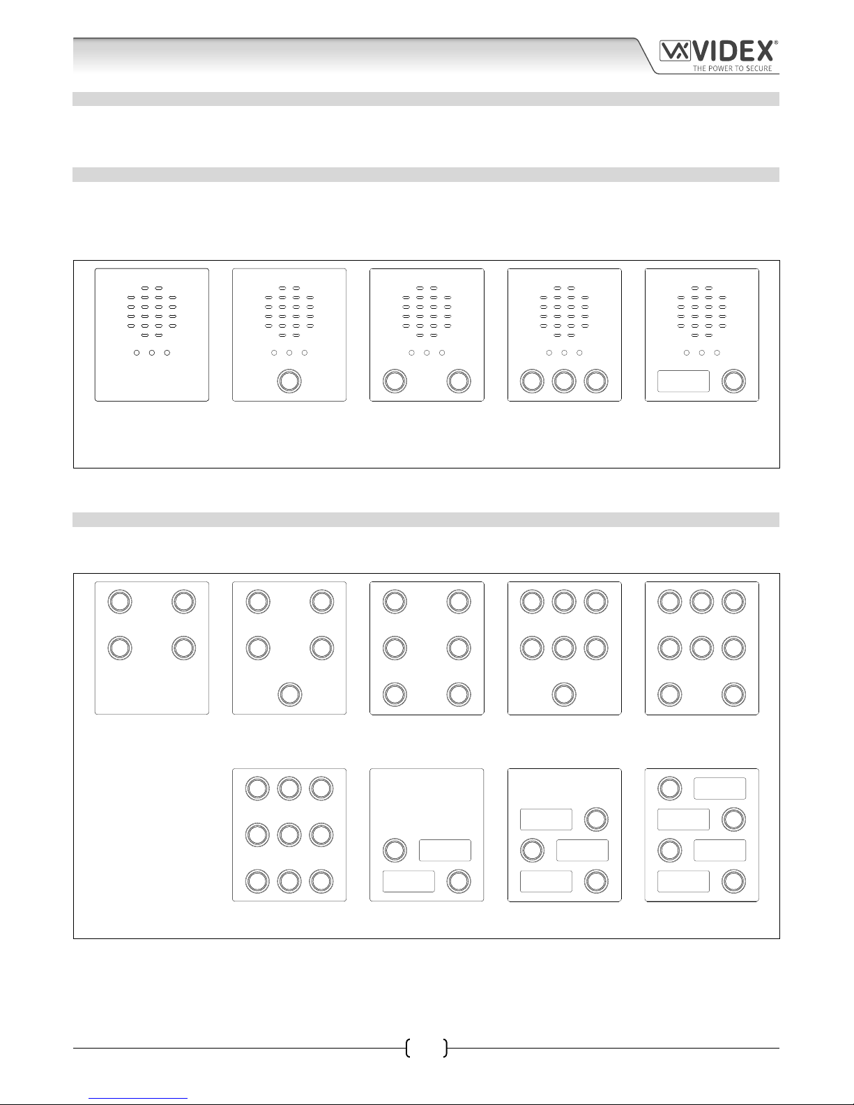
The intercom panel can include any of the modules from the 4000 series vandal resistant range and uses the standard 4000 series
surface and ush mounting frames. The GSM module is however essential and includes all the GSM communication electronics,
SIM card (supplied separately) and connections. The intercom module is available in a 0 button, 1 button, 2 button, 3 button and 1
button with nameplate conguration, as shown in Fig.1, along with their part numbers.
SPEAK BUSY OPENSPEAK BUSY OPEN SPEAK BUSY OPEN
SPEAK BUSY OPEN
SPEAK BUSY OPEN SPEAK BUSY OPEN
VR4KGSM-0 VR4KGSM-1 VR4KGSM-2 VR4KGSM-3 VR4KGSM-1NP
VR4KGSM-0/3G VR4KGSM-1/Y VR4KGSM-2/Y VR4KGSM-3/Y VR4KGSM-1NP/3G
VR4KGSM-1/3G VR4KGSM-2/3G VR4KGSM-3/3G
Fig. 1 VR4KGSM-1/Y/3G VR4KGSM-2/Y/3G VR4KGSM-3/Y/3G
Standard versions of theVR4KGSM modules (e.g. VR4KGSM-0 etc.) works on a 2G network A 3G variant is also available (see Fig.1
above) that works on a 3G network, sux /3G to the part number as shown.
EXTENSION BUTTON MODULES
The GSM intercom module will accept up to 24 call buttons. Any of the standard 4000 series vandal resistant button modules can
be used as shown in Fig.2 along with their part numbers.
VR4KBM-4 VR4KBM-5 VR4KBM-6 VR4KBM-7 VR4KBM-8
VR4KBM-4/Y VR4KBM-5/Y VR4KBM-6/Y VR4KBM-7/Y VR4KBM-8/Y
VR4KBM-9 VR4KBM-2NP VR4KBM-3NP VR4KBM-4NP
Fig. 2 VR4KBM-9/Y
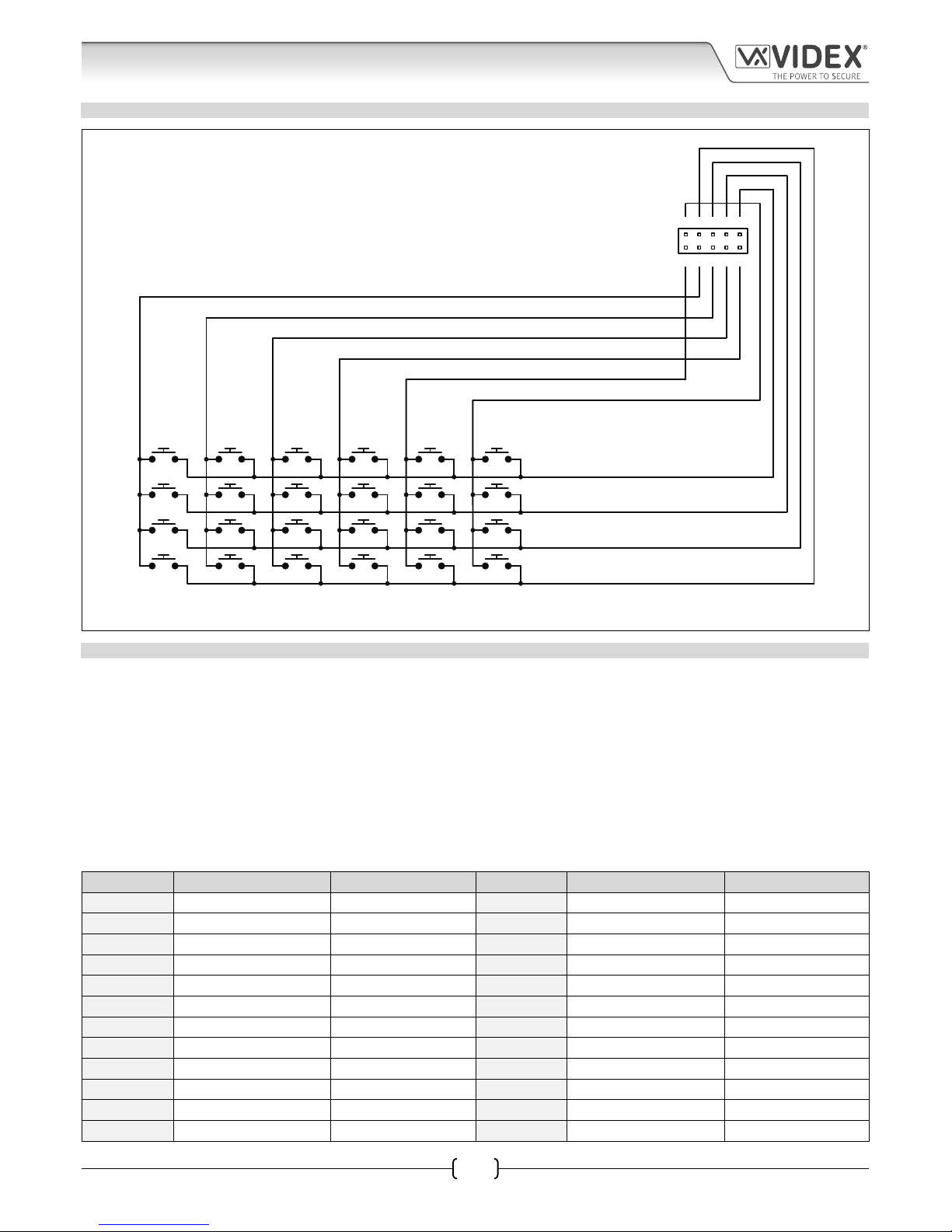
Button connections to the GSM module are shown in Fig.3 on page 7 (only the wiring of the button harness is shown). It is important
to take care when using additional button modules with a GSM intercom module which also has onboard buttons. For example,
an intercom module with one button (VR4KGSM-1) means the extension button module used must start wiring from button 2 on
the button harness (the green “b” and white “1” wires would be used), an intercom module with 2 buttons (VR4KGSM-2) means the
extension button module used must start wiring from button 3 on the button harness (the blue “c” and white “1” wires would be
used) and so on.
System Components and Available Versions
Page 7
66250675-EN - V1.0 - 05/09/17
7
4000 Series Vandal Resistant GSM Audio Intercom with Proximity Facility
4000 Series Vandal Resistant GSM - Technical Manual
BUTTON HARNESS WIRING
6abcd
51234
8
7
6
5
4
3
2
1
12
11
10
9
16
15
14
13
20
19
18
17
24
23
22
21
white wire
red wire
brown wire
black wire
grey wire
yellow wire
violet wire
blue wire
green wire
orange wire
button harness connector
Fig. 3
BUTTON MODULE NOTES
If the GSM module has 1 button (VR4KGSM-1), the additional button module buttons should be wired starting from button number
2 (i.e. the rst button of the button module should be connected using the green “b” and white “1” wires, the next button using the
blue “c” and white “1” wires etc.).
If the GSM module has 2 buttons (VR4KGSM-2), the additional button module buttons should be wired starting from button number
3 (i.e. the rst button of the button module should be connected using the blue “c” and white “1” wires, the next button using the
violet “d” and white “1” wires etc.).
If the GSM module has 3 buttons (VR4KGSM-3), the additional button module buttons should be wired starting from button number
4 (i.e. the rst button of the button module should be connected using the violet “d” and white “1” wires, the next button using the
orange “a” and pink “2” wires etc.).
The button harness table below can also be used to determine the required button module wiring.
Button No. Harness Connector Pins Wire Colours Button No. Harness Connector Pins Wire Colours
1 a - 1 orange / white 13 a - 4 orange / black
2 b - 1 green / white 14 b - 4 green / black
3 c - 1 blue / white 15 c - 4 blue / black
4 d - 1 violet / white 16 d - 4 violet / black
5 a - 2 orange / red 17 a - 5 orange / grey
6 b - 2 green / red 18 b - 5 green / grey
7 c - 2 blue / red 19 c - 5 blue / grey
8 d - 2 violet / red 20 d - 5 violet / grey
9 a - 3 orange / brown 21 a - 6 orange / yellow
10 b - 3 green / brown 22 b - 6 green / yellow
11 c - 3 blue / brown 23 c - 6 blue / yellow
12 d - 3 violet / brown 24 d - 6 violet / yellow
System Components and Available Versions
Page 8
66250675-EN - V1.0 - 05/09/17
8
4000 Series Vandal Resistant GSM Audio Intercom with Proximity Facility
4000 Series Vandal Resistant GSM - Technical Manual
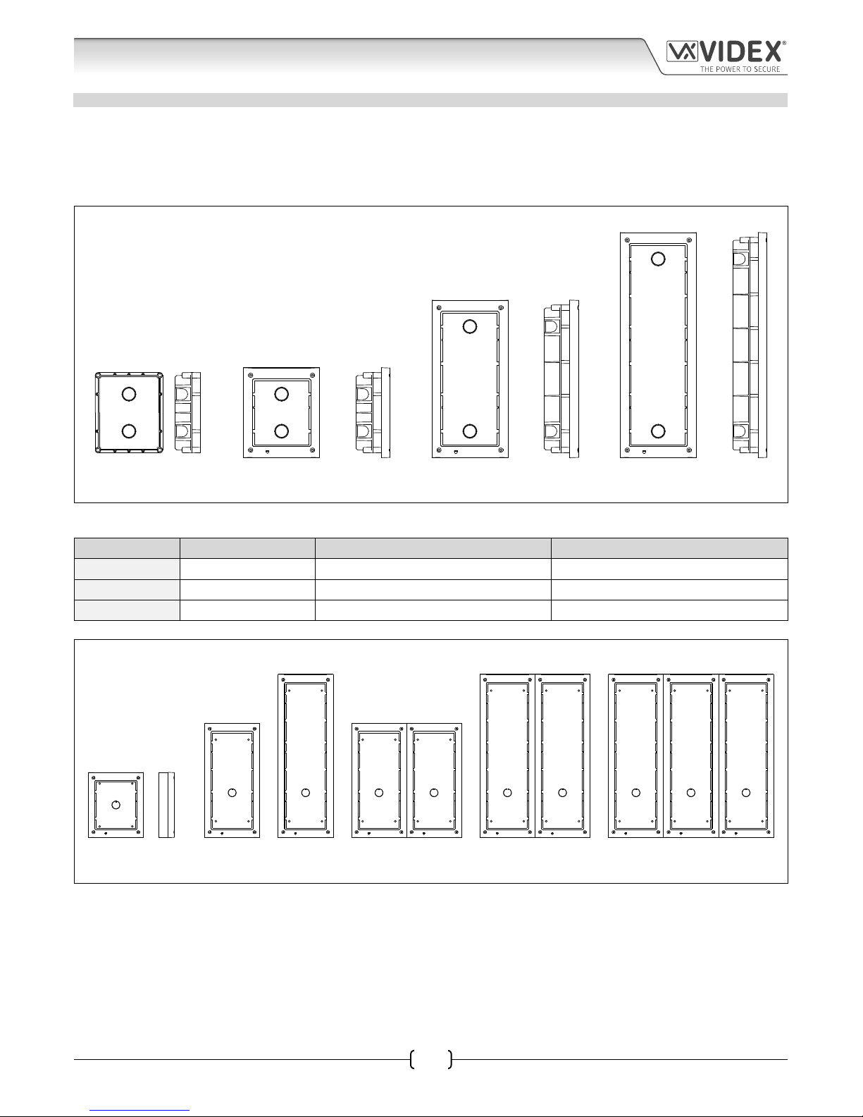
4000 SERIES BACK BOXES AND MOUNTING FRAMES
Both surface and ush back boxes and mounting frames are available. The size of the frame will depend on the number of modules
that make up the GSMVRK/GSMVRKC kit. The last digit of the frame code indicates the number of modules it will take. Frames are
available in gun metal gray nish, chrome nish (sux \C to the frame code) or gold nish (sux \G to the frame code). The 4000
series mounting frames available are shown in Fig.4 (ush) and Fig.5 (surface) with the following tables showing the back box
dimensions.
Flush Back Boxes and Mounting Frames
Art. 4851 Art. 4852 Art. 4853
Fig. 4
Flush Back Box Dimensions
Part No. Housed Modules Front Frame (W x H x D) mm Back Box (W x H x D) mm
Art.4851 1 135 x 160 x 15.7 120 x 143 x 46
Art.4852 2 135 x 280.2 x 15.7 120 x 263.2 x 46
Art.4853 3 135 x 400.4 x 15.7 120 x 383.4 x 46
Surface Back Boxes and Mounting Frames
Art. 4881 Art. 4882 Art. 4883 Art. 4884 Art. 4886 Art. 4889
Fig. 5
System Components and Available Versions
Page 9
66250675-EN - V1.0 - 05/09/17
9
4000 Series Vandal Resistant GSM Audio Intercom with Proximity Facility
4000 Series Vandal Resistant GSM - Technical Manual
System Components and Available Versions
Surface Back Box Dimensions
Part No. Housed Modules No. of Columns Back Box (W x H x D) mm
Art.4881 1 1 135 x 160 x 43
Art.4882 2 1 135 x 280.2 x 43
Art.4883 3 1 135 x 400.4 x 43
Art.4884 4 2 270 x 280.2 x 43
Art.4886 6 2 270 x 400.4 x 43
Art.4889 9 3 405 x 400.4 x 43
DL1512, 12VDC 1.25A POWER SUPPLY
The VR4KGSM (Art.150) module is designed to work with power supplies in the
range of 12Vdc-14Vdc and should be capable of supplying a constant current
of no less than 1.25A. Both the GSMVRK and GSMVRKC kits are supplied with a
12Vdc 2A power supply the DL-15-12 psu (refer to Fig.6).
Fig. 6
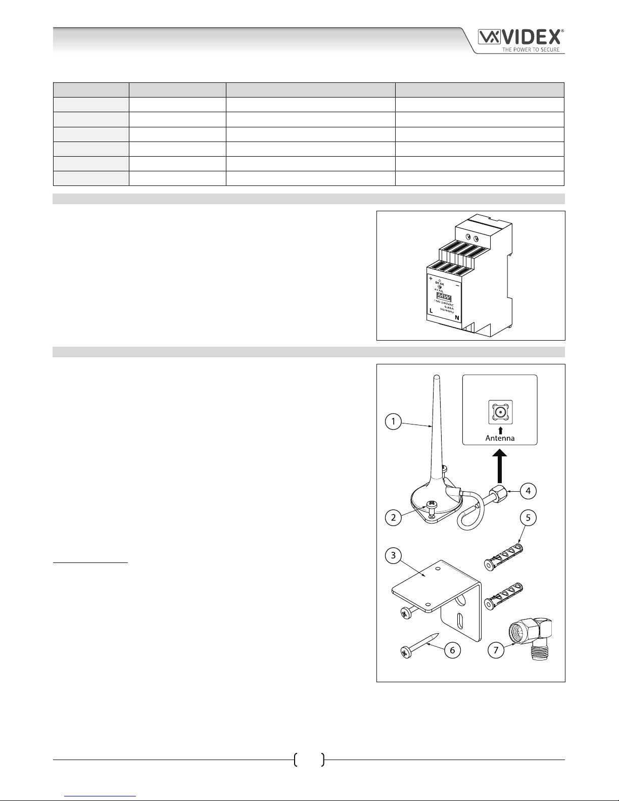
ART. 432 GSM ANTENNA
The Art.432 GSM antenna connects to the SMA female bulkhead connection on
the rear of the Art.150 GSM module. A GSM antenna with an SMA male connector
should be used (refer to Fig.7).
Antenna Parts
1. GSM antenna with magnetic base.
2. Self-threading screw (Ø3.5mm x 9.5mm).
3. Aluminium L bracket for mounting.
4. SMA male connector (cable length 2.5m).
5. Expansion type wall plugs (Ø6mm).
6. Self-threading screw (Ø4mm x 30mm).
7. Right angled SMA adapter.
IMPORTANT NOTE: An antenna must always be tted for the GSM module to
work. Always route the GSM antenna cable away from the microphone wires
and the power supply wires to avoid interference on the speech channels.
In instances where there is a tight tting space for the SMA male connector on
the antenna cable the right angled SMA adapter can be used to help reroute the
cable down the back side of the GSM module.
Fig. 7
SMA female bulkhead
connection on rear of
VR4KGSM module
Page 10
66250675-EN - V1.0 - 05/09/17
10
4000 Series Vandal Resistant GSM Audio Intercom with Proximity Facility
4000 Series Vandal Resistant GSM - Technical Manual
System Components and Available Versions
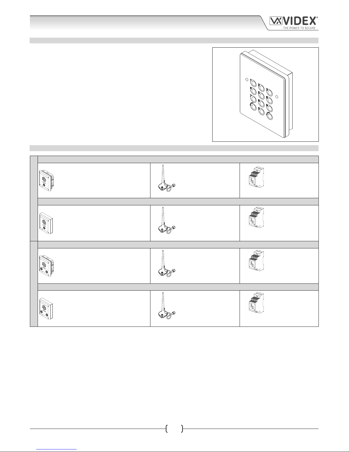
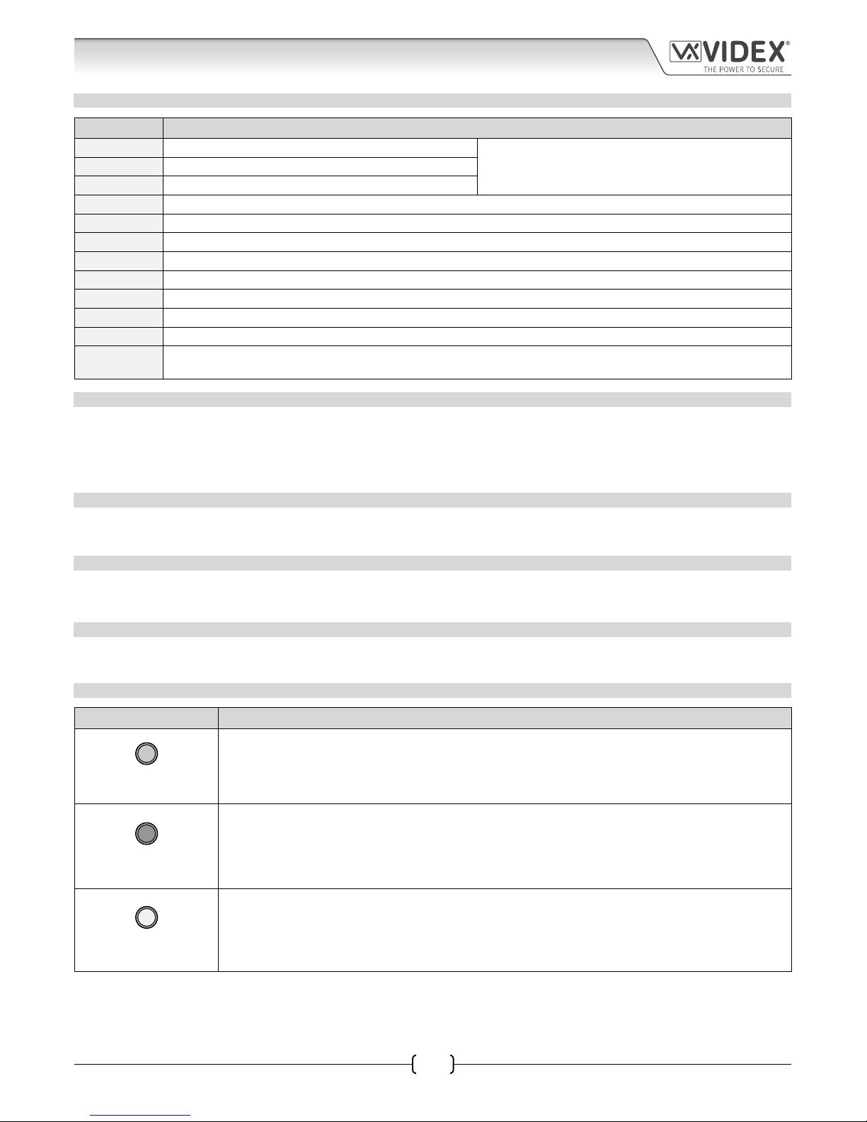
ART. VR4KCLM CODELOCK
The VR4KCLM codelock module (included as part of the GSMVRKC kits), see
Fig.8, can be powered from 12-24V AC or DC and includes three dry contact
relay outputs and two switched 0V push to exit inputs which can be used to
trigger relay 1 & 2.
One code per relay can be programmed into the device. Codes can be between
4 - 8 digits long.
The relay time can be 01 - 99 seconds or set for latching (00). When in latching
mode, enter the code followed by ‘ENTER’ to latch the relay and the code
followed by ‘CLEAR’ to unlatch the relay.
Fig. 8
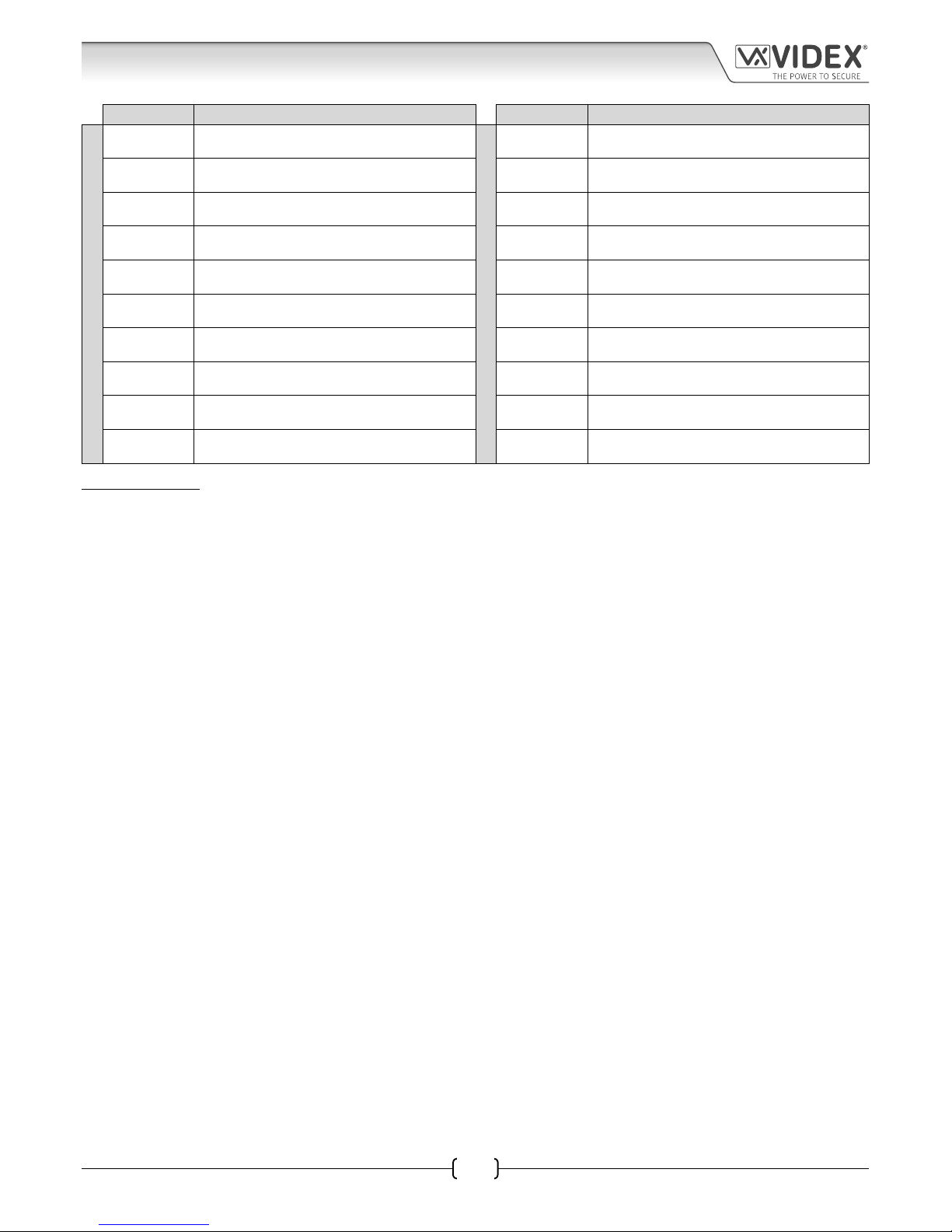
VANDAL RESISTANT GSM INTERCOM AUDIO KITS
ONE WAY VERSIONS
GSMVRK-1 - ush mounting
1 Outdoor station composed of:
1 Art.VR4KGSM-1: 1 button VR GSM unit
1 Art.4851: Flush mounting box
1 GSM antenna
Art.432
1 Power supply
DL-15-12
12Vdc 1.25A
GSMVRK-1S - surface mounting
1 Outdoor station composed of:
1 Art.VR4KGSM-1: 1 button VR GSM unit
1 Art.4881: Surface mounting box
1 GSM antenna
Art.432
1 Power supply
DL-15-12
12Vdc 1.25A
TWO WAY VERSIONS
GSMVRK-2 - ush mounting
1 Outdoor station composed of:
1 Art.VR4KGSM-2: 2 button VR GSM unit
1 Art.4851: Flush mounting box
1 GSM antenna
Art.432
1 Power supply
DL-15-12
12Vdc 1.25A
GSMVRK-2S - surface mounting
1 Outdoor station composed of:
1 Art.VR4KGSM-2: 2 button VR GSM unit
1 Art.4881: Surface mounting box
1 GSM antenna
Art.432
1 Power supply
DL-15-12
12Vdc 1.25A
Page 11

66250675-EN - V1.0 - 05/09/17
11
4000 Series Vandal Resistant GSM Audio Intercom with Proximity Facility
4000 Series Vandal Resistant GSM - Technical Manual
ONE WAY VERSIONS
GSMVRKC-1 - ush mounting
1 Outdoor station composed of:
1 Art. VR4KGSM-1: 1 button VR GSM unit
1 Art.VR4KCLM-1: VR4K series codelock
1 Art.4852: Flush mounting box
1 GSM antenna
Art.432
1 Power supply
DL-15-12
12Vdc 1.25A
GSMVRKC-1S - surface mounting
1 Outdoor station composed of:
1 Art. VR4KGSM-1: 1 button VR GSM unit
1 Art.VR4KCLM-1: VR4K series codelock
1 Art.4882: Surface mounting box
1 GSM antenna
Art.432
1 Power supply
DL-15-12
12Vdc 1.25A
TWO WAY VERSIONS
GSMVRKC-2 - ush mounting
1 Outdoor station composed of:
1 Art.VR4KGSM-2: 2 button VR GSM unit
1 Art.VR4KCLM-1: VR4K series codelock
1 Art.4852: Flush mounting box
1 GSM antenna
Art.432
1 Power supply
DL-15-12
12Vdc 1.25A
GSMVRKC-2S - surface mounting
1 Outdoor station composed of:
1 Art.VR4KGSM-2: 2 button VR GSM unit
1 Art.VR4KCLM-1: VR4K series codelock
1 Art.4882: Surface mounting box
1 GSM antenna
Art.432
1 Power supply
DL-15-12
12Vdc 1.25A
GSMVRK AUDIO KITS
Additional GSMVRK-n (ush) kit versions available from 3 way kits up to 12 way kits: GSMVRK-3 up to GSMVRK-12. Each audio kit
comes with the appropriate VR4KGSM module, appropriate extension button module(s) and appropriate ush back box depending
on the GSMVRK-n kit required (where n = the number of call buttons), refer to table below.
Additional GSMVRK-nS (surface) kit versions available from 3 way kits up to 12 way kits: GSMVRK-3S to GSMVRK-12S. Each audio
kit comes with the appropriate VR4KGSM module, appropriate extension button module(s) and appropriate surface back box
depending on the GSMVRK-nS kit required (where n = the number of call buttons), refer to table below.
Kit No. Outdoor station composed of: Kit No. Outdoor station composed of:
FLUSH
GSMVRK-3 1 Art.VR4KGSM-3; 1 Art.4851
SURFACE
GSMVRK-3S 1 Art.VR4KGSM-3; 1 Art.4881
GSMVRK-4 1 Art.VR4KGSM-0; 1 Art.VR4KBM-4; 1 Art.4852 GSMVRK-4S 1 Art.VR4KGSM-0; 1 Art.VR4KBM-4; 1 Art.4882
GSMVRK-5 1 Art.VR4KGSM-0; 1 Art.VR4KBM-5; 1 Art.4852 GSMVRK-5S 1 Art.VR4KGSM-0; 1 Art.VR4KBM-5; 1 Art.4882
GSMVRK-6 1 Art.VR4KGSM-0; 1 Art.VR4KBM-6; 1 Art.4852 GSMVRK-6S 1 Art.VR4KGSM-0; 1 Art.VR4KBM-6; 1 Art.4882
GSMVRK-7 1 Art.VR4KGSM-0; 1 Art.VR4KBM-7; 1 Art.4852 GSMVRK-7S 1 Art.VR4KGSM-0; 1 Art.VR4KBM-7; 1 Art.4882
GSMVRK-8 1 Art.VR4KGSM-0; 1 Art.VR4KBM-8; 1 Art.4852 GSMVRK-8S 1 Art.VR4KGSM-0; 1 Art.VR4KBM-8; 1 Art.4882
GSMVRK-9 1 Art.VR4KGSM-0; 1 Art.VR4KBM-9; 1 Art.4852 GSMVRK-9S 1 Art.VR4KGSM-0; 1 Art.VR4KBM-9; 1 Art.4882
GSMVRK-10 1 Art.VR4KGSM-1; 1 Art.VR4KBM-9; 1 Art.4852 GSMVRK-10S 1 Art.VR4KGSM-1; 1 Art.VR4KBM-9; 1 Art.4882
GSMVRK-11 1 Art.VR4KGSM-2; 1 Art.VR4KBM-9; 1 Art.4852 GSMVRK-11S 1 Art.VR4KGSM-2; 1 Art.VR4KBM-9; 1 Art.4882
GSMVRK-12 1 Art.VR4KGSM-3; 1 Art.VR4KBM-9; 1 Art.4852 GSMVRK-12S 1 Art.VR4KGSM-3; 1 Art.VR4KBM-9; 1 Art.4882
GSMVRKC AUDIO KITS
Additional GSMVRKC-n (ush) kit versions available from 3 way kits up to 12 way kits: GSMVRKC-3 up to GSMVRKC-12. Each
audio kit comes with the appropriate VR4KGSM module, appropriate extension button module(s), VR4KCLM codelock module and
appropriate ush back box depending on the GSMVRKC-n kit required (where n = the number of call buttons), refer to table of page
12.
Additional GSMVRKC-nS (surface) kit versions available from 3 way kits up to 12 way kits: GSMVRK-3S to GSMVRK-12S. Each
audio kit comes with the appropriate VR4KGSM module, appropriate extension button module(s), VR4KCLM codelock module and
appropriate surface back box depending on the GSMVRKC-nS kit required (where n = the number of call buttons), refer to table on
page 12.
System Components and Available Versions
Page 12
66250675-EN - V1.0 - 05/09/17
12
4000 Series Vandal Resistant GSM Audio Intercom with Proximity Facility
4000 Series Vandal Resistant GSM - Technical Manual
System Components and Available Versions
Kit No. Outdoor station composed of: Kit No. Outdoor station composed of:
FLUSH
GSMVRKC-3 1 Art.VR4KGSM-3; 1 Art.VR4KCLM; 1 Art.4852
SURFACE
GSMVRKC-3S 1 Art.VR4KGSM-3; 1 Art.VR4KCLM; 1 Art.4882
GSMVRKC-4
1 Art.VR4KGSM-0; 1 Art.VR4KBM-4;
1 Art.VR4KCLM; 1 Art.4853
GSMVRKC-4S
1 Art.VR4KGSM-0; 1 Art.VR4KBM-4;
1 Art.VR4KCLM; 1 Art.4883
GSMVRKC-5
1 Art.VR4KGSM-0; 1 Art.VR4KBM-5;
1 Art.VR4KCLM; 1 Art.4853
GSMVRKC-5S
1 Art.VR4KGSM-0; 1 Art.VR4KBM-5;
1 Art.VR4KCLM; 1 Art.4883
GSMVRKC-6
1 Art.VR4KGSM-0; 1 Art.VR4KBM-6;
1 Art.VR4KCLM; 1 Art.4853
GSMVRKC-6S
1 Art.VR4KGSM-0; 1 Art.VR4KBM-6;
1 Art.VR4KCLM; 1 Art.4883
GSMVRKC-7
1 Art.VR4KGSM-0; 1 Art.VR4KBM-7;
1 Art.VR4KCLM; 1 Art.4853
GSMVRKC-7S
1 Art.VR4KGSM-0; 1 Art.VR4KBM-7;
1 Art.VR4KCLM; 1 Art.4883
GSMVRKC-8
1 Art.VR4KGSM-0; 1 Art.VR4KBM-8;
1 Art.VR4KCLM; 1 Art.4853
GSMVRKC-8S
1 Art.VR4KGSM-0; 1 Art.VR4KBM-8;
1 Art.VR4KCLM; 1 Art.4883
GSMVRKC-9
1 Art.VR4KGSM-0; 1 Art.VR4KBM-9;
1 Art.VR4KCLM; 1 Art.4853
GSMVRKC-9S
1 Art.VR4KGSM-0; 1 Art.VR4KBM-9;
1 Art.VR4KCLM; 1 Art.4883
GSMVRKC-10
1 Art.VR4KGSM-1; 1 Art.VR4KBM-9;
1 Art.VR4KCLM; 1 Art.4853
GSMVRKC-10S
1 Art.VR4KGSM-1; 1 Art.VR4KBM-9;
1 Art.VR4KCLM; 1 Art.4883
GSMVRKC-11
1 Art.VR4KGSM-2; 1 Art.VR4KBM-9;
1 Art.VR4KCLM; 1 Art.4853
GSMVRKC-11S
1 Art.VR4KGSM-2; 1 Art.VR4KBM-9;
1 Art.VR4KCLM; 1 Art.4883
GSMVRKC-12
1 Art.VR4KGSM-3; 1 Art.VR4KBM-9;
1 Art.VR4KCLM; 1 Art.4853
GSMVRKC-12S
1 Art.VR4KGSM-3; 1 Art.VR4KBM-9;
1 Art.VR4KCLM; 1 Art.4883
IMPORTANT NOTE: The GSM audio kits listed above work on a 2G network. For the 3G variant remember to sux the kit part
no. with /3G, e.g. GSMVRK-7/3G, GSMVRKC-10S/3G etc.
Page 13
66250675-EN - V1.0 - 05/09/17
13
4000 Series Vandal Resistant GSM Audio Intercom with Proximity Facility
4000 Series Vandal Resistant GSM - Technical Manual
Technical Information
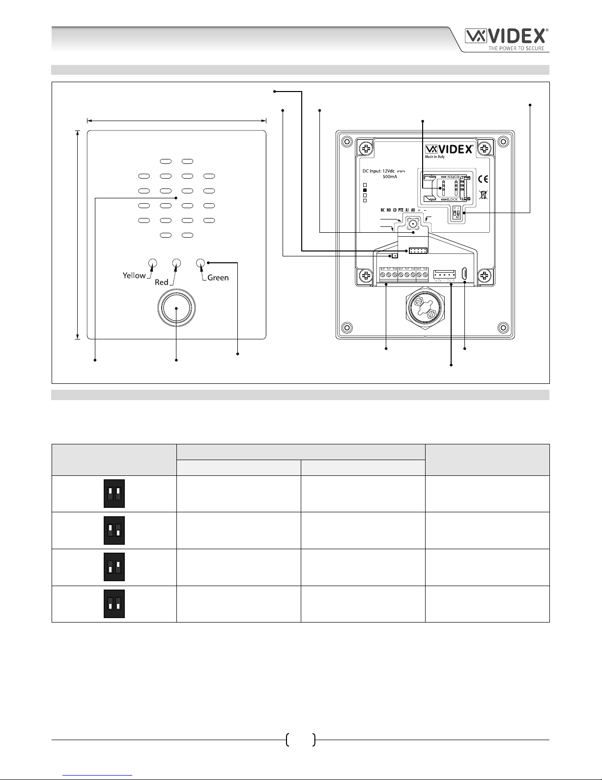
ART. VR4KGSM MODULE
SPEAK BUSY OPEN
103mm
120mm
CN3
CN1
USB
CN6
CN5
Art.150
GSM Unit for VR Panels
Antenna
Wiegand
Button
Harness
UIM-138 USB
VR4KGSM-0
VR4KGSM-1
VR4KGSM-2
VR4KGSM-3
Fig. 9
SPEAKER VOLUME ADJUSTMENT DIPSWITCH SETTINGS
There are 2 dip-switches located on the back of the VR4KGSM module under the SIM card holder, see Fig.9. They can be used to
adjust the volume from the door intercom speaker (see table below). Additionally, the volume can also be adjusted during a call
electronically via the telephone keypad (refer to user command table 1 on page 51).
Dip-Switch
Dip-Switch Status
Gain (dB)
Dip No.1 Dip No.2
12
ON
ON ON 6
12
ON
ON OFF 12
12
ON
OFF ON 18
12
ON
OFF OFF 23.5
Call progress LED’s
(speak, busy & open)
Terminal connections
SIM card holder
Intercom speaker
Speaker volume dip-switches
Display interface connection
Micro USB
connection
Antenna connectionWiegand reader connection
Button harness connection
Call button
Page 14
66250675-EN - V1.0 - 05/09/17
14
4000 Series Vandal Resistant GSM Audio Intercom with Proximity Facility
4000 Series Vandal Resistant GSM - Technical Manual
TERMINAL CONNECTIONS AND HARNESS CONNECTIONS
Terminal Description
NC Normally oclosed relay contact.
Relay contacts:
3A@24Vdc
3A@120Vac
NO Normally open relay contact.
CO Common relay contact.
PTE Push to exit input (switched 0V).
AI Auxiliary input (switched 0V).
AO Auxiliary output (open collector, 150mA max.)
+ +12Vdc power input (500mA max.)
– 0V ground power.
USB Micro USB connection (CN1).
UIM-138 Display interface harness connection (CN3).
Wiegand Wiegand proximity reader harness connection (CN5).
Button
Harness
Pre-wired button harness connection (CN6). Refer to Fig.3 and button harness table on page 7 for wiring colour
codes and button congurations.
USB CONNECTION CN1
The micro-USB connection allows the VR4KGSM module to be connected to a laptop/PC for ease of programming (refer to page 28
for connecting the GSM module to a laptop/PC). Further information on programming using the GSMSK PC software can be found
in the following manual:
GSMSK-66251720-EN-V1-3 (or later version)
UIM138 DISPLAY HARNESS INTERFACE CONNECTION, CN3
The UIM-138 connection allows the VR4KGSM module to be connected to the display interface module, the VR4KDM, (refer to page
20 for connecting the GSM module to a VR4KDM module.
WIEGAND WIEGAND PROXIMITY READER HARNESS CONNECTION, CN5
The Wiegand connection allows for a Wiegand proximity reader, the VR4KPPM, to be connected to the VR4KGSM module (refer to
page nn for connections). Further information on programming proximity fobs/cards can be found on pages nn - nn of this manual.
BUTTON HARNESS CONNECTIONS CN6
The pre-wired button harness is used to connect the buttons and button modules (described on page 6) to the VR4KGSM module.
For complete button harness wiring refer to Fig.3 and the button harness table on page 7.
CALL PROGRESS LED’S
LED (sign) Description
SPEAK
(Yellow)
The speak LED when illuminated, indicates that it is possible to speak because the call has been
answered or a call made to the GSM intercom (with the exception of a call from a dial to open (DTO)
number). The LED will switch OFF at the end of a conversation when the telephone/mobile that has
been dialled hangs up or at the end of the call time (SPT).
BUSY
(Red)
The busy LED when illuminated, indicates that it is not possible to make a call because a call or a
conversation is in progress. The LED will be OFF when the system is in standby. If there is power on
the GSM intercom and the Art.432 antenna is not connected this LED will ash continuously until the
antenna is connected. The LED will ash while connecting to a network and continue to ash until it
has found the network.
OPEN
(Green)
The open LED when illuminated, indicates that the door lock (GSM relay) has been operated. It will
switch OFF at the end of the programmed “door opening” time. The LED will also illuminate and operate
the relay (for the programmed relay, RLT, time) if a programmed key fob is presented to an o board
Wiegand proximity reader that is connected to the Wiegand reader input connections.
Technical Information
Page 15
66250675-EN - V1.0 - 05/09/17
15
4000 Series Vandal Resistant GSM Audio Intercom with Proximity Facility
4000 Series Vandal Resistant GSM - Technical Manual
TECHNICAL SPECIFICATION
Working Voltage : 12Vdc +/- 10%
Standby Current : approx. 60mA
Max. Current : approx. 500mA (max.)
Call Buttons : up to 24 (max.)
Telephone Numbers per Button : 4 telephone numbers (1 primary, 3 diverts)
Dial to Open Numbers : up to 1000 (max.)
Wiegand Proximity Connection : 1, for connection of a Wiegand proximity reader the Art.VR4KPPM
Proximity Access (fobs/cards) : up to 1000 users (max.)
Call Progress LED’s : 4 (busy, call, speak and open)
Programming : SMS messaging or PC software
Push to Exit : 1 (switched 0V across terminals PTE/-)
Auxiliary Inputs : 1 (switched 0V across terminals AI/-)
Auxiliary Outputs : 1 (AO, open collector output, switched 0V, 150mA max.)
Dry Contact Relay : 1, 3A @ 24Vdc, 3A @ 120Vac
Event Log : up to 4000 events
USB Port : micro USB
Display Module Interface : 1, for connection of the Art.VR4KDM (UIM-138) display interface module
Timebands : 1 programmable timeband
Dimensions : 103mm (W) x 120mm (L) x 37mm (D)
Working Temp. : -10 +50
o
C
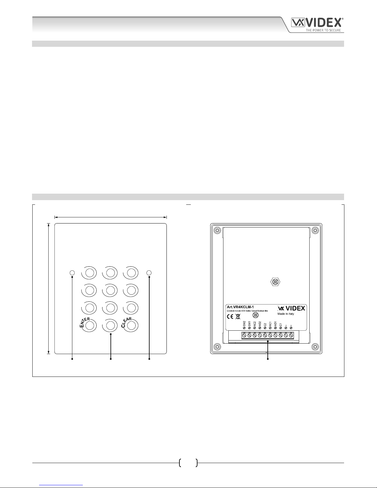
ART. VR4KCLM1 CODELOCK MODULE
1 2 3
4 65
7 98
0
103mm
120mm
VR4800-10
CO2
Fig. 10
The VR4KCLM-1 codelock module (see Fig.10) can be connected to the GSM intercom and is supplied with the GSMVRKC kits. It can
be programmed with 2 access codes, one per relay (also see notes on page 10).
Technical Information
green
accept LED
red prog. LEDkeypad terminal connections
Page 16
66250675-EN - V1.0 - 05/09/17
16
4000 Series Vandal Resistant GSM Audio Intercom with Proximity Facility
4000 Series Vandal Resistant GSM - Technical Manual
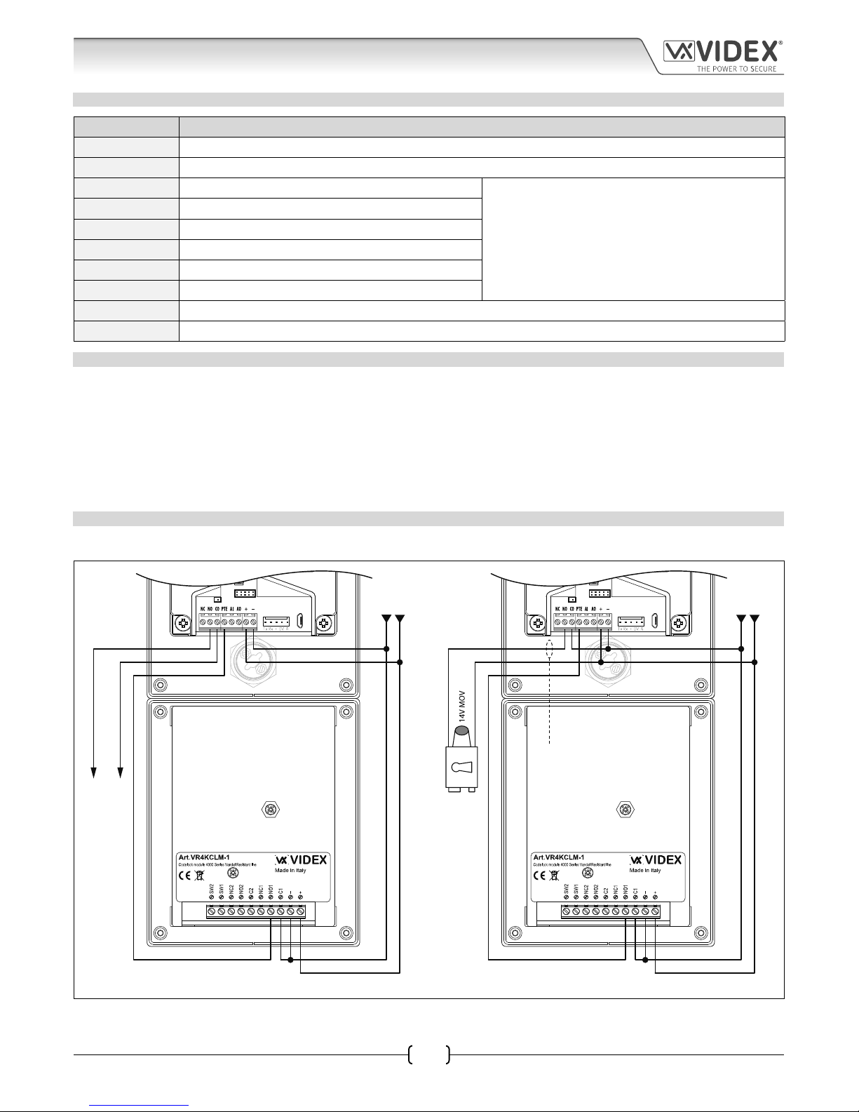
TERMINAL CONNECTIONS
Connection Description
+ 12-24V AC or DC power input
- 0V power input
C1 Relay 1 common connection
Relay contacts:
3A@24Vac/dc
NO1 Relay 1 normally open connection
NC1 Relay 1 normally closed connection
C2 Relay 2 common connection
NO2 Relay 2 normally open connection
NC2 Relay 2 normally closed connection
SW1 Switched 0V input to trigger relay 1
SW2 Switched 0V input to trigger relay 2
TECHNICAL SPECIFICATION
Working Voltage : 12V - 24Vac/dc +/- 10%
Current (standby) : 20mA
Current (during operation) : 70mA (max.)
Dry Contact Relays : 2, relay 1 and relay 2, 3A @ 24Vac/dc (max.)
Relay Codes : 2 (one code per relay, 4 - 6 digits)
Push to Exit : 2, SW1 and SW2 (switched 0V across terminals SW1/- for relay 1 and SW2/- for relay 2)
Dimensions : 103mm (W) x 120mm (L) x 40mm (D)
Working Temp. : -10 +50
o
C
CONNECTING THE CODELOCK TO THE GSM INTERCOM
Follow the connections as shown in Fig.11 when connecting the VR4KCLM-1 codelock to the GSM intercom.
VR4800-10
CO2
CN3
CN1
USB
CN6
Wiegand
UIM-138 USB
VOLT FREE
RELAY CONTACTS
1
0V
+12Vdc
VR4800-10
CO2
CN3
CN1
USB
CN6
Wiegand
UIM-138 USB
0V
+12Vdc
FAIL SECURE
LOCK RELEASE
1
Fig. 11
Remember to set the VR4KCLM-1 relay time to a shorter time than that of the GSM relay time (RLT).
for fail safe lock wiring move
lock wire from NO to NC
Technical Information
Page 17
66250675-EN - V1.0 - 05/09/17
17
4000 Series Vandal Resistant GSM Audio Intercom with Proximity Facility
4000 Series Vandal Resistant GSM - Technical Manual
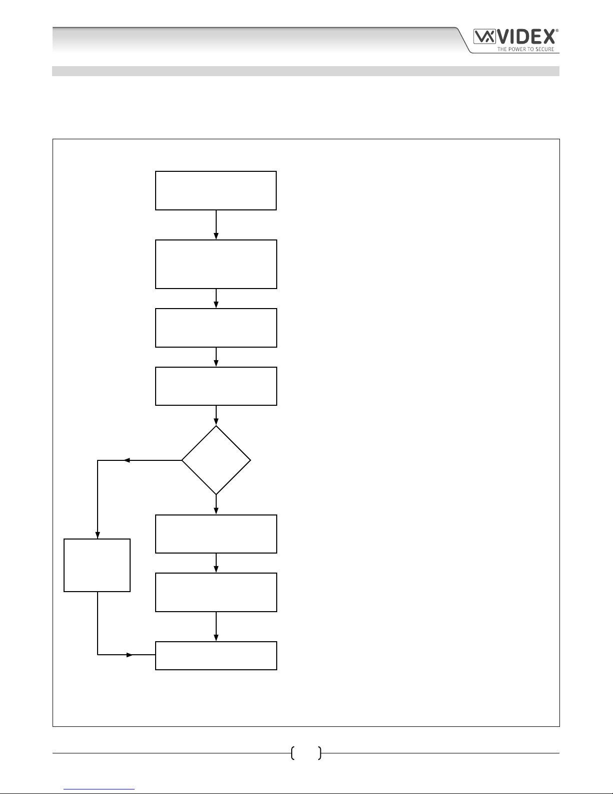
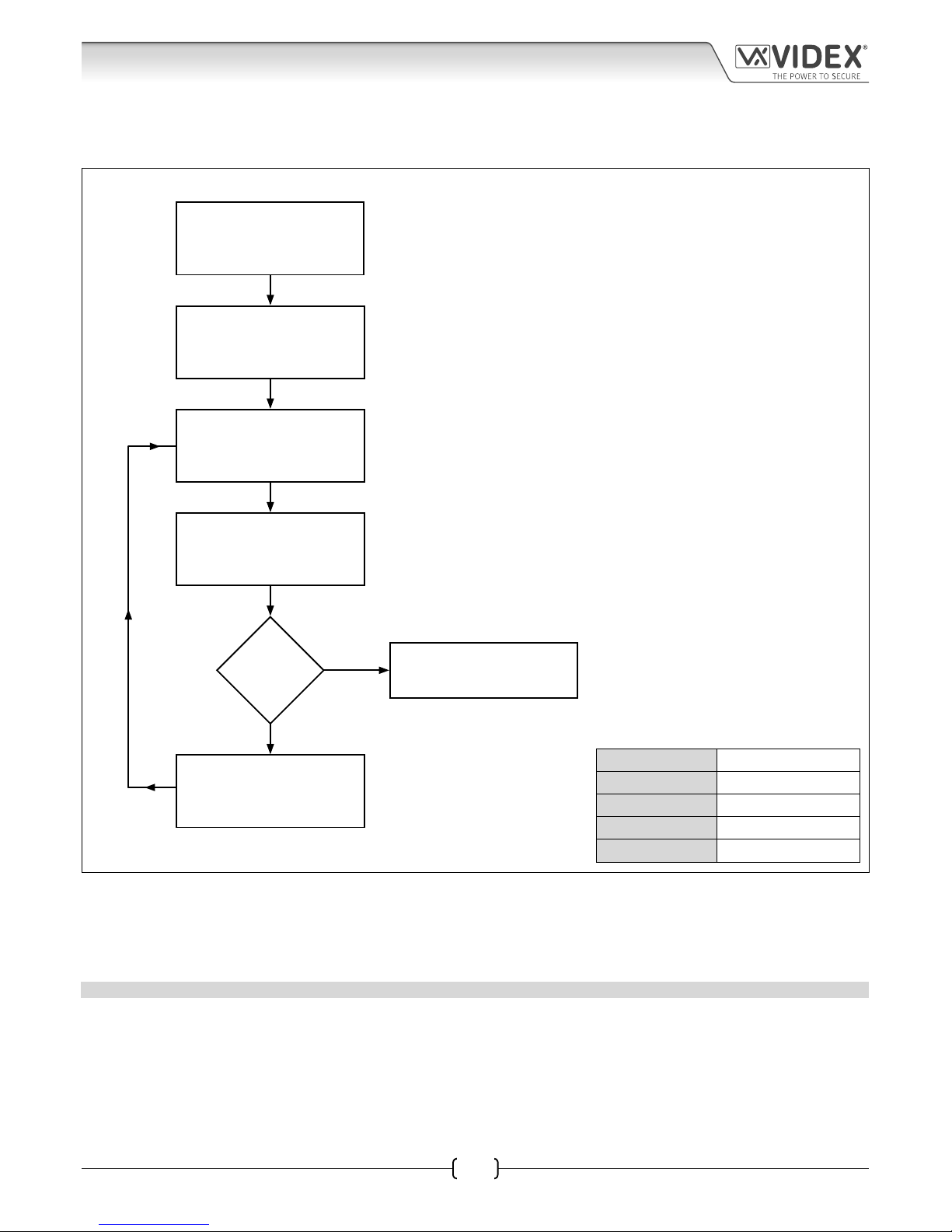
ART. VR4KCLM1 PROGRAMMING GUIDE
Initial Programming
All programming is carried out using the keypad. The programming menu is protected by an engineer’s code. The factory default
engineer’s code is ‘111111’ (6x1). This code can be changed to any 4 to 6 digit engineer’s code during the programming, but must
be dierent to the access codes used to gain entry. Follow the ow chart below to setup the access codes:
Technical Information
The red LED will illuminate to acknowledge the Art.VR4KCLM-1 is in programming
mode. If the red LED does not illuminate check the engineer’s code is correct. If
the engineer’s code has been changed from the factory default and you do not
know what it is then follow the factory default procedure on page 18.
Enter a new engineer’s code
or enter the same engineer’s
code again.
Then press ENTER.
Enter the access code
for relay 1.
Then press ENTER.
Enter a two digit relay 1 time
from 00 - 99 seconds.
Then press ENTER.
Enter the default engineer’s
code ‘111111’.
Then press ENTER.
More codes?
Enter a two digit relay 2
time from 00 - 99 seconds.
Then press ENTER.
SYSTEM READY
TO USE
Enter the access code
for relay 2.
Then press ENTER.
YES
NO
This new engineer’s code can be from 4 – 8 digits long and will not activate the
relays. It can only be used to enter programming mode. Please note that this new
engineer’s code will be needed to re-program the Art.VR4KCLM-1 relay codes in
the future.
This access code will be used to open the door/gate for relay 1. The code can be
from 4 – 8 digits long and must be dierent from the engineer’s code.
This is the time that relay 1 will activate for. It is a two digit number, for example
if relay 1 needs to activate for 5 seconds then enter ‘05’ followed by ENTER. ‘00’
will latch the relay when the access code is entered and require the access code
followed by CLEAR to unlatch.
This access code will be used to open the door/gate for relay 2. The code can
be from 4 – 8 digits long and must be dierent from the engineer’s code and
dierent from the previous access codes.
This is the time that relay 2 will activate for. It is a two digit number, for example
if relay 2 needs to activate for 5 seconds then enter ‘05’ followed by ENTER. ‘00’
will latch the relay when the access code is entered and require the access code
followed by CLEAR to unlatch.
The Art.VR4KCLM-1 codelock will play a melody and the red LED will switch OFF
to conrm all the settings are saved and exit from programming mode.
Melody
Melody
Melody
Melody
Melody
Melody
Press ENTER
twice to
exit
programming
Page 18
66250675-EN - V1.0 - 05/09/17
18
4000 Series Vandal Resistant GSM Audio Intercom with Proximity Facility
4000 Series Vandal Resistant GSM - Technical Manual
Re-programming the Codelock
If the VR4KCLM-1 codelock has been programmed with an existing access code and it needs to be changed then follow the ow
chart below to re-program a new acces code:
Re-enter the existing
engineer’s code again.
Then press ENTER.
Enter a new access
code for the relay.
Then press ENTER.
Enter a two digit relay time
from 00 - 99 seconds.
Then press ENTER.
Enter the existing
engineer’s code.
Then press ENTER.
More codes?
Repeat steps for a new
access code and time
for relay 2
Press ENTER twice to
exit programming
YES
NO
The red LED will illuminate to indicate that
the codelock is in programming mode 2.
Alternatively enter a new eningeer’s code (4 - 6 digits).
Relay access code (4 - 6 digits) that operates the door or gate 3
2 digit relay time (01 - 99 seconds or 00 for latching).
The red LED will switch OFF to
indicate that the codelock has
exited programming mode.
Melody
Melody
Melody
Melody
Melody
Programming Notes
If the red LED does not illuminate then the engineer’s code has been previously changed or is incorrect. To reset this code follow
the factory reset procedure below.
On the rst loop of the ow chart above the access code is for relay 1 on the second loop the access code is for relay 2.
RESETTING THE ENGINEER’S CODE BACK TO FACTORY DEFAULT ‘111111’ 6x1
1. Remove/disconnect the power from the VR4KCLM-1 codelock.
2. Press and hold down the ENTER button while the power is switched back onto the codelock.
3. Once power is restored to the codelock release the ENTER button.
4. The engineer’s code has been reset back to the factory default of ‘111111’ (6x1).
Engineer’s Code
Relay 1 Code
Relay 1 Time
Relay 2 Code
Relay 2 Time
Technical Information
Page 19

66250675-EN - V1.0 - 05/09/17
19
4000 Series Vandal Resistant GSM Audio Intercom with Proximity Facility
4000 Series Vandal Resistant GSM - Technical Manual
Additional Modules
As previously mentioned on page 14 additional modules can be connected to the vandal resistant GSM intercom:
• a display interface module the VR4KDM;
• an o-board Wiegand proximity reader the VR4KPPM (XPROX).
ART. VR4KDM DISPLAY INTERFACE MODULE
The VR4KDM display interface module (as shown in Fig.12) can be connected to the GSM module using the ‘plug-in’ UIM-138
connection harness. The module aids users with disabilities to make the process of calling a number or apartment more user friendly
helping comply with the Equality Act 2010.
The VR4KDM module has a 2 line 16 character blue back-lit LCD which is protected behind a 6mm lexan window and displays the
call progress information whilst also producing spoken call progress messages through the speaker of the GSM module.
Programming of the display module can be carried out using the current VX2X00 programming software (version 7.0.0.17 or later)
allowing user names, apartment numbers and additional displayed messages to be programmed. The VR4KDM module connects
to the GSM intercom using the ‘plug-in’ connector described above and then connects to the PC/laptop using a standard USB cable
connection (refer to the connection diagram, Fig.15, on page 20).
Further programming information can be found in the following technical manual:
• UIM-138 Display Module Manual - Technical Manual Edition 1.0.
103mm
120mm
UIM-138
User information module
Made in Italy
USB 0V A0 I1 I2 I3 I4 I5
Up Down High Low
UIM138 1.3 - UIM138 SP10
Art. VR4KDM
Fig. 12
CONTRAST ADJUSTMENT AND SPEECH ANNUNCIATION VOLUME CONTROLS
There are 2 adjustment controls on the back of the display module, see Fig.12 above. The ‘CON’ adjustment POT controls the
contrast and ‘back-lit’ intensity of the display; turning the POT anti-clockwise increases the contrast and intensity of the display;
turning the POT clockwise decreases the contrast and intensity of the display, see Fig.13. The ‘VOL’ adjustment POT controls the
speech annunciation volume through the GSM module’s speaker; turning the POT anti-clockwise turns the speech volume high;
turning the POT clockwise turns the speech volume low, see Fig.14.
UP DOWN
CON
HIGH LOW
VOL
Fig. 13 Fig. 14
Terminal connections
display contrast adjustment
2 line 16 character blue back-lit display
USB connection
UIM-138 harness connection
speech annunciation volume adjustment
Page 20

66250675-EN - V1.0 - 05/09/17
20
4000 Series Vandal Resistant GSM Audio Intercom with Proximity Facility
4000 Series Vandal Resistant GSM - Technical Manual
TERMINAL CONNECTIONS, HARNESS CONNECTIONS AND USB INPUT
Terminal Description
0V Switched 0V input.
AO Programmable auxiliary output (switched 0V).
I1
5 programmable auxiliary inputs. To program these inputs please refer to the technical manual:
UIM-138 Display Module Manual - Technical Manual Edition 1.0
I2
I3
I4
I5
UIM-138 Harness
Connection
5 pin UIM-138 harness input to CN3 connection on the GSM module.
(see connection diagram below).
USB Input
USB cable input to connect laptop ⁄ PC for programming the VR4KDM module.
(see connection diagram below).
TECHNICAL SPECIFICATION
Working Voltage : 12 - 14Vdc +/- 10%
Standby Current : approx. 29mA
Max. Current : approx. 34mA (max.)
Harness Connection : 5 pin connector
USB Port : standard USB cable input
Dimensions : 103mm (W) x 120mm (L) x 32mm (D)
Working Temp. : -10 +50
o
C
CONNECTING THE VR4KDM TO THE GSM MODULE
Fig.15 below shows how to connect the display module to the vandal resistant GSM module using the UIM-138 connection harness
and then connecting the display module to a laptop/PC via the USB cable input.
UIM-138
User information module
Made in Italy
USB 0VA0 I1 I2 I3 I4 I5
Up Down High Low
UIM138 1.3 - UIM138 SP10
Art. VR4KDM
CN3
CN1
USB
CN6
CN5
CN1
CN
Art.150
GSM Unit for VR Panels
Antenna
Wiegand
Button
Harness
UIM-138 USB
VR4KGSM-0
VR4KGSM-1
VR4KGSM-2
VR4KGSM-3
Antenna
PC
USB cable UIM-138 harness
Fig. 15
Additional Modules
Page 21

66250675-EN - V1.0 - 05/09/17
21
4000 Series Vandal Resistant GSM Audio Intercom with Proximity Facility
4000 Series Vandal Resistant GSM - Technical Manual
ART. VR4KPPM WIEGAND PROXIMITY READER
The VR4KPPM Wiegand proximity reader (as shown in Fig.16) can be connected to the GSM module using the ‘plug-in’ proximity
connection harness. Further information on programming proximity fobs/cards can be found on pages 46 and 47 of this manual.
103mm
120mm
+LR
-LR
+LG
-LG
D1/DATA
D0/CLOCK/DATA
Art. VR4KPPM (XPROX)
Fig. 16
TERMINAL CONNECTIONS
Connection Description
1 +LR Access denied (red) LED +positive connection.
2LR Access denied (red) LED -negative switch connection.
3+LG Access granted (green) LED +positive connection.
4LG Access granted (green) LED -negative switch connection.
5 D1/DATA Data connection.
D0 and D1 Wiegand clock and data terminals.
6 D0/CLOCK/DATA Clock data connection.
7 0V ground power input.
8+ 12Vdc power input.
TECHNICAL SPECIFICATION
Working Voltage : 12Vdc +/- 10%
Current (standby) : 20mA
Current (during operation) : 70mA (max.)
Wiegand Connection : D0 and D1 clock and data
Dimensions : 103mm (W) x 120mm (L) x 30mm (D)
Working Temp. : -10 +50
o
C
Additional Modules
Terminal connectionsData/standby LED
(amber)
Access granted LED
(green)
Access denied LED
(red)
Page 22

66250675-EN - V1.0 - 05/09/17
22
4000 Series Vandal Resistant GSM Audio Intercom with Proximity Facility
4000 Series Vandal Resistant GSM - Technical Manual
Additional Modules
CONNECTING THE VR4KPPM TO THE GSM INTERCOM
Follow the connections as shown in Fig.17 when connecting the VR4KPPM Wiegand proximity module to the GSM intercom when
using the ‘plug-in’ proximity connection harness. The table below shows the harness signal colours.
Connection Signal Harness Wire Colour
1 +LR red wire linked across to terminals 3 and 8 (+positive).
2LR orange wire (red LED).
3+LG red wire linked across to terminals 1 and 8 (+positive).
4LG green wire (green LED).
5 D1/DATA yellow wire (data)
6 D0/CLOCK/DATA white wire (data).
7 black wire (0V).
8+ red wire linked across to terminals 3 and 1 (+positive).
+LR
-LR
+LG
-LG
D1/DATA
D0/CLOCK/DATA
Art. VR4KPPM (XPROX)
CN3
CN1
USB
CN6
CN5
Art.150
GSM Unit for VR Panels
Antenna
Wiegand
Button
Harness
UIM-138 USB
VR4KGSM-0
VR4KGSM-1
VR4KGSM-2
VR4KGSM-3
red
black
white
orange
green
yellow
CN1
CN1
Antenna
Fig. 17
Page 23

66250675-EN - V1.0 - 05/09/17
23
4000 Series Vandal Resistant GSM - Technical Manual
4000 Series Vandal Resistant GSM Audio Intercom with Proximity Facility
Wiring Diagrams
GSMVRK CONNECTIONS
Fig.18 shows the wiring connections for a GSMVRK-1 / GSMVRK-1S audio kit.
Fig. 18
CN3
CN1
USB
CN6
CN5
Art.150
GSM Unit for VR Panels
Antenna
Wiegand
Button
Harness
UIM-138 USB
VR4KGSM-0
VR4KGSM-1
VR4KGSM-2
VR4KGSM-3
CN1
CN1
FAIL SECURE
LOCK RELEASE
GSMVRKC CONNECTIONS
Fig.19 shows connections for a GSMVRKC-1 / GSMVRKC-1S audio kit (also see Fig.11 on page 16 for volt free connections and fail
secure lock wiring).
Fig. 19
VR4800-10
CO2
CN3
CN1
USB
CN6
CN5
Art.150
GSM Unit for VR Panels
Antenna
Wiegand
Button
Harness
UIM-138 USB
VR4KGSM-0
VR4KGSM-1
VR4KGSM-2
VR4KGSM-3
CN1
CN1
FAIL SAFE
LOCK RELEASE
4
Remember to set the VR4KCLM-1 relay time to a shorter time than that of the GSM relay time (RLT).
for fail secure lock wiring move
lock wire from NC to NO.
Page 24

66250675-EN - V1.0 - 05/09/17
24
4000 Series Vandal Resistant GSM - Technical Manual
4000 Series Vandal Resistant GSM Audio Intercom with Proximity Facility
Wiring Diagrams
CONNECTING TO A GATE CONTROLLER
If the GSM intercom is going to be connected to an electric gate then the wires from the gate controls can be connected directly
into the CO and NO relay terminals on the GSM module. Follow the connections shown in Fig.20.
Fig. 20
CN3
CN1
USB
CN6
CN5
Art.150
GSM Unit for VR Panels
Antenna
Wiegand
Button
Harness
UIM-138 USB
VR4KGSM-0
VR4KGSM-1
VR4KGSM-2
VR4KGSM-3
CN1
CN1
VOLT FREE
CONTACTS TO
GATE CONTROLS
CONNECTING A PUSH TO EXIT BUTTON
The push to exit button must be congured as a push-to-make switch and connected across terminals PTE & - (0V) on the GSM
module. When the exit button is pressed the GSM relay will trigger for the programmed time, RLT (see Fig.21).
Fig. 21
CN3
CN1
USB
CN6
CN5
Art.150
GSM Unit for VR Panels
Antenna
Wiegand
Button
Harness
UIM-138 USB
VR4KGSM-0
VR4KGSM-1
VR4KGSM-2
VR4KGSM-3
CN1
CN1
VOLT FREE
CONTACTS
Page 25

66250675-EN - V1.0 - 05/09/17
25
4000 Series Vandal Resistant GSM - Technical Manual
4000 Series Vandal Resistant GSM Audio Intercom with Proximity Facility
Wiring Diagrams
CONNECTING A TRADE BUTTON USING AN ART. 701T 28G TIMECLOCK
If required a digital timeclock, the Art.701T, can be used for connecting a trade button. First isolate a button either on the VR4KGSM
module or VR4K button module (see button module variations in Fig.1 and Fig.2 on page 6). Connect the isolated button to the
Art.701T timeclock as shown in Fig.22. The timeclock should be set to timeclock mode (see Fig.22). For programming and set up of
the timeclock please refer to the Art.701T (28G) Installation Instructions: 66250340-701T-EN-V1.1.
When the programmed timeband is reached on the timeclock pressing the trade button will trigger the GSM module’s push to exit
(PTE) input and the GSM relay will trigger for the programmed time, RLT.
CN3
CN1
USB
CN6
CN5
Art.150
GSM Unit for VR Panels
Antenna
Wiegand
Button
Harness
UIM-138 USB
VR4KGSM-0
VR4KGSM-1
VR4KGSM-2
VR4KGSM-3
CN1
CN1
VOLT FREE
CONTACTS
Isolated Trade button (from VR4KGSM module
or VR4K button module) wired into PTE input
Fig. 22
Page 26

66250675-EN - V1.0 - 05/09/17
26
4000 Series Vandal Resistant GSM - Technical Manual
4000 Series Vandal Resistant GSM Audio Intercom with Proximity Facility
Auxiliary Input & Output
The GSM’s auxiliary output can be programmed to 3 dierent modes (00 - 02), please refer to programming notes on how to set up
the auxiliary output mode (A1M) on page 41.
AUXILIARY OUTPUT AO WHEN SET TO MODE 00 ON DURING A CALL
Fig.23 below shows the connection for auxiliary output AO when the A1M mode is set to 00. The auxiliary output AO will activate
once a call to an apartment has been made and will stay activated for the duration of the call.
CN3
CN1
USB
CN6
CN5
Art.150
GSM Unit for VR Panels
Antenna
Wiegand
Button
Harness
UIM-138 USB
VR4KGSM-0
VR4KGSM-1
VR4KGSM-2
VR4KGSM-3
CN1
CN1
When the auxiliary output mode (A1M) is set to mode 00. The
auxiliary output AO will activate from when a call is made to
an apartment and stay activated for the duration of the call.
When the call is nished the auxiliary output AO will deactivate.
Fig. 23
AUXILIARY INPUT AI AND AUXILIARY OUTPUT AO WHEN SET TO MODE 01 ON WHEN TRIGGERED
Fig.24 below shows the connection for auxiliary output AO when the A1M mode is set to 01. The auxiliary output AO can be
activated remotely by the user sending the text message 1111A1O to the GSM intercom or by pressing 6 on the telephone during a
call and will stay activated for the programmed auxiliary output time A1T. The auxiliary output can also be triggered by a normally
open switch (switched 0V) connected into the auxiliary input AI.
CN3
CN1
USB
CN6
CN5
Art.150
GSM Unit for VR Panels
Antenna
Wiegand
Button
Harness
UIM-138 USB
VR4KGSM-0
VR4KGSM-1
VR4KGSM-2
VR4KGSM-3
CN1
CN1
The auxiliary output AO will activate for the
programmed auxiliary output time (A1T) when the
auxiliary input AI is triggered from a normally open
switch (switched 0V) and the auxiliary output mode
(A1M) is set to mode 01.
The auxiliary output AO can also be triggered
remotely by sending the text message 1111A1O to
the GSM module or by pressing 6 on the telephone
during a call.
Fig. 24
Page 27

66250675-EN - V1.0 - 05/09/17
27
4000 Series Vandal Resistant GSM - Technical Manual
4000 Series Vandal Resistant GSM Audio Intercom with Proximity Facility
Auxiliary Input & Output
AUXILIARY OUTPUT AO WHEN SET TO MODE 02 CALL ACTIVATED
Fig.25 below shows the connection for auxiliary output AO when the A1M mode is set to 02. The auxiliary output AO will activate
once a call to an apartment has been made and will stay activated for the programmed auxiliary output time A1T.
CN3
CN1
USB
CN6
CN5
Art.150
GSM Unit for VR Panels
Antenna
Wiegand
Button
Harness
UIM-138 USB
VR4KGSM-0
VR4KGSM-1
VR4KGSM-2
VR4KGSM-3
CN1
CN1
When the auxiliary output mode (A1M) is set to mode 02. The
auxiliary output AO will activate from when a call is made to an
apartment and stay activated for the auxiliary output time (A1T).
Fig. 25
CONNECTING A SECONDARY DEVICE TO THE AUXILIARY OUTPUT AO
Since the auxiliary output AO is a transistor switched output (switched low output) it can be connected to a relay (e.g. an Art.506N).
This is particularly useful if a secondary device requires triggering. Fig.26 shows how to connect an Art.506N relay.
CN3
CN1
USB
CN6
CN5
Art.150
GSM Unit for VR Panels
Antenna
Wiegand
Button
Harness
UIM-138 USB
VR4KGSM-0
VR4KGSM-1
VR4KGSM-2
VR4KGSM-3
CN1
CN1
VOLT FREE
CONTACTS
Fig. 26
Page 28

66250675-EN - V1.0 - 05/09/17
28
4000 Series Vandal Resistant GSM - Technical Manual
4000 Series Vandal Resistant GSM Audio Intercom with Proximity Facility
USB Connection
CONNECTIONS TO A PC
The vandal resistant GSM intercom also includes a micro-USB connection allowing the module to be connected to a laptop/
PC for ease of programming and for downloading the event log. Programming is carried out using the GSMSK PC software. All
programming features described in this manual are also accessible using the software. Further information on using the GSMSK PC
software can be found in the technical manual GSMSK-66251720-EN-V1-3 (or later version).
USB CONNECTION
The GSM module can be connected using a standard micro-USB to USB cable as shown in Fig.27.
CN3
CN1
USB
CN6
CN5
Art.150
GSM Unit for VR Panels
Antenna
Wiegand
Button
Harness
UIM-138 USB
VR4KGSM-0
VR4KGSM-1
VR4KGSM-2
VR4KGSM-3
CN1
CN1
PC
micro-USB/USB
cable
Fig. 27
IMPORTANT NOTE: The USB is not intended for a permanent connection to a PC and should only be used for programming and
setup of the GSMVRK module.
Page 29

66250675-EN - V1.0 - 05/09/17
29
4000 Series Vandal Resistant GSM - Technical Manual
4000 Series Vandal Resistant GSM Audio Intercom with Proximity Facility
CABLE SIZE GUIDE
Refer to the table below for the connections for the power supply output to the VR4KGSM intercom and the lock release connections.
Distance 20m 50m 100m
Cross Sectional Area (CSA) 0.5mm
2
1.0mm
2
1.5mm
2
Ideally the power supply should be located as close to the intercom panel as possible for best performance. The maximum
acceptable resistance for the above cables = 3Ω or less for best possible performance.
IMPORTANT NOTE: Only bare copper (BC) cable should be used (solid or stranded is acceptable). Please be aware that when
selecting a cable the following should NOT be used: Copper Coated Steel (CCS) and Copper Clad Aluminium (CCA). While these
types of cable may oer a low cost solution they will have a higher resistance than pure copper cable and can aect the overall
performance of the system therefore Videx DO NOT recommend these types of cable.
GENERAL INSTALLATION NOTES
• Check that all components are free from damage before installing (do not proceed with installation in the event of damage).
• Keep all packaging away from children.
• Do not obstruct the ventilation openings or slots on any of the devices.
• All connections to mains voltages must be made to the current national standards (I.E.E. wiring regulations or the
appropriate standards of your country).
• Install an appropriate fused spur or isolation switch to isolate the mains.
• Isolate the mains before carrying out any maintenance work on the system.
• Avoid water ingress into the rear of the module, always seal the module frame after installation using a suitable silicon
based sealant.
• All intercom and access control cables must be routed separately from the mains.
LOCK RELEASE WIRING AND BACK EMF PROTECTION
When tting an electric lock release back EMF protection will be required. If tting an AC lock release then a 100nF ceramic disc
capacitor must be tted across the terminals of the lock, shown in Fig.28. If tting a DC lock release (fail secure or fail safe) then a
1N4002 diode must be tted across the terminals on the lock, shown in Fig.29.
100nF CAP
+
-
1N4002 DIODE
Fig. 28 Fig. 29
If a 100nF ceramic disc capacitor or a 1N4002 diode are not available then a 14 - 20V MOV (metal oxide varistor) can be tted across
the lock terminals instead (refer to Fig.28 above) and can be tted on both an AC and DC lock. Connection examples can also be
seen on the wiring diagrams on pages 16 and 23.
General Directions for Installation
Page 30

66250675-EN - V1.0 - 05/09/17
30
4000 Series Vandal Resistant GSM - Technical Manual
4000 Series Vandal Resistant GSM Audio Intercom with Proximity Facility
General Directions for Installation
CONNECTION TO MAINS, SAFETY AND GUIDANCE NOTES
IMPORTANT: PLEASE READ THESE INSTRUCTIONS CAREFULLY BEFORE COMMENCING WITH THE INSTALLATION.
Videx recommends that any cabling and Videx product be installed by a competent and qualied electrician, security installation
speclialist or communications engineer.
• DO NOT install any Videx product in areas where the following may be present or occur:
• Excessive oil or a grease laden atmosphere.
• Corrosive or ammable gases, liquids or vapours.
• Possible obstructions which would prevent or hinder the access and/or removal of the Videx product.
MAINS CONNECTION
The system MUST be installed in accordance with the current I.E.E regulations (in particular I.E.E. Wiring regulations BS7671), or the
appropriate standards of your country, in particular Videx recommends:
• Connecting the system to the mains through an all-pole circuit breaker (refer to Fig.30) which shall have contact separation
of at least 3mm in each pole and shall disconnect all poles simultaneously.
• That the all-pole circuit breaker shall be placed in such a way to allow for easy access and the switch shall remain readily
operable.
• Ensuring that the mains supply (Voltage, Frequency and Phase) complies with the product rating label.
• Isolating the mains before carrying out any maintenance work on the system.
FUSE
N
L
Mains
1 PHASE SUPPLY
(220 - 240Vac, 50/60Hz)
SWITCHED FUSE SPUR
Fig. 30
POWER SUPPLY INSTALLATION
Follow the steps below when tting the DL-15-12, 12Vdc 1.25A power supply.
• First remove the terminal side covers by unscrewing the retaining screws (if applicable).
• Fix the power supply to a DIN rail (following Fig.31, Fig.32 and Fig.33).
• Switch OFF the mains using the circuit breaker (mentioned previously) and then make the connections as shown on the
installation diagrams.
• Check the connections and secure the wires into the terminals ensuring that the low voltage (signal) cables are routed
separately from the high voltage (mains) cables.
• Replace the terminal covers and x them back into place using the relevant screws (if applicable).
• When all connections are made restore the mains supply.
Page 31

66250675-EN - V1.0 - 05/09/17
31
4000 Series Vandal Resistant GSM - Technical Manual
4000 Series Vandal Resistant GSM Audio Intercom with Proximity Facility
Fig. 31 Fig. 32
Fig. 33
PANEL CARE
The digital GSM panel facia is brushed stainless steel. It is important that the facia is cleaned on regular occasions to prevent dirt
build up and tarnishing of the metal. A general household metal polish can be used but care should be taken to follow the grain
of the metal when polishing and also avoid any polish build up around the panel buttons which may prevent the buttons from
operating correctly.
General Directions for Installation
Page 32

66250675-EN - V1.0 - 05/09/17
32
4000 Series Vandal Resistant GSM - Technical Manual
4000 Series Vandal Resistant GSM Audio Intercom with Proximity Facility
Fitting the SIM & Connecting Power
FITTING THE SIM CARD AND CONNECTING THE POWER TO THE GSM INTERCOM
After connecting the power supply, antenna, lock output and any auxiliary devices as shown in this manual and before powering
up, a SIM card must be installed (the SIM must already be registered with the network provider). The SIM holder can be found on the
back of the module next to the SMA antenna connection. A SIM card from most network providers can be used with the exception
of the 3 network. Follow the steps below to insert the SIM card:
1. On the GSM module slide the SIM holder on the back
of the unit to the right until it ‘clicks’, as shown in Fig.34.
2. The SIM holder is hinged and will open out to the right,
see Fig.35.
3. Place the SIM card into the holder (it will only t one
way, see Fig.36) and fold the holder back down, see
Fig.37.
4. Slide the SIM holder back to the left until it ‘clicks’, see
Fig.38.
5. Once the SIM is in place connect the appropriate call
buttons following the example shown in Fig.3 and
using the table on page 7 of this manual.
6. Connect the Art.432 GSM antenna and then connect
the DR-15-12, 12Vdc power supply but DO NOT power
up the system yet.
7. Follow the initialisation process described below.
Fig. 34 Fig. 35
Fig. 36 Fig. 37
Fig. 38
POWER UP INITIALISATION SEQUENCE
The GSM module requires approximately 30 seconds to initialise properly. We recommend
NOT sending SMS messages or pressing buttons during this time.
1. First check all the connections have been made correctly and then power up the
system.
2. Two short beeps will be heard from the GSM module and the busy LED will switch
ON, as shown in Fig.39.
3. After approximately 10 seconds the busy LED will start to ash for a further 10
seconds and then emit a single beep, as shown in Fig.40.
4. The busy LED will continue to ash while it registers with the chosen network.
5. After a further delay the busy LED will stop ashing to indicate that the GSM module
has registered with the network and is ready to begin programming.
If you hear a dierent combination of beeps during the initialisation process then you
can nd the meaning of these beeps towards the back of the manual.
Fig. 39
Fig. 40
SPEAK BUSY OPEN
SPEAK BUSY OPEN
Page 33

66250675-EN - V1.0 - 05/09/17
33
4000 Series Vandal Resistant GSM - Technical Manual
4000 Series Vandal Resistant GSM Audio Intercom with Proximity Facility
Reset Procedure
RESETTING THE GSM MODULE TO FACTORY DEFAULTS
There are two reset options for the GSM module. The rst will reset the master code only and the second will reset everything and
clear all stored telephone numbers, proximity cards and settings.
RESETTING THE MASTER CODE TO 1111 4x1
1. Ensure the power is switched OFF to the GSM module;
2. Short out the blue (c) and yellow (6) wires together from the button harness cable
(refer to Fig.3 and the button harness table on page 7);
3. Switch the power back ON to the GSM module;
4. Two short beeps will be heard from the GSM module and the busy LED will switch
ON, as shown in Fig.41;
5. After approximately 5 seconds the busy LED will start to ash;
6. The busy LED will continue to ash for a further 15-20 seconds while it resets the
master code and then emit a single beep, as shown in Fig.42;
7. After a short delay of approximately 5 seconds the busy LED will stop ashing,
as shown in Fig.43, to indicate that the master code has been reset back to the
factory default 1111 (4x1);
8. After the reset remove the short between the blue (c) and yellow (6) wires.
IMPORTANT NOTE: When a master code reset is performed on the GSM module it
will only reset the 4 digit programming code back to factory default 1111, all the
settings and programmed information (telephone numbers, proximity fobs/cards,
etc.) will still be stored in the GSM module.
Fig. 41
Fig. 42
Fig. 43
FULL SYSTEM RESET
1. Ensure the power is switched OFF to the GSM module;
2. Short out the violet (d) and yellow (6) wires together from the button harness
cable (refer to Fig.3 and the button harness table on page 7);
3. Switch the power back ON to the GSM module;
4. Two short beeps will be heard from the GSM module and the busy LED will switch
ON, as shown in Fig.44;
5. After approximately 8 seconds the busy LED will start to ash as shown in Fig.45;
6. The busy LED will continue to ash while it resets the GSM module;
7. After a short delay of approximately 6 seconds the busy LED will stop ashing and
the GSM will emit a single beep to indicate that the module has been fully reset,
as shown in Fig.46. All the settings will be reset back to factory default and any
stored user information etc. will be deleted from the module;
8. After the reset remove the short between the violet (d) and yellow (6) wires.
IMPORTANT NOTE: When a full system reset is performed on the GSM module it
will default any settings back to factory presets and delete all the user information
(telephone numbers, proximity fobs/cards etc.). This method of reset clears all the
programming in the GSM module so it is advisable to save or record the information
beforehand.
If a high volume of information is stored in the GSM module it can be downloaded
and saved using the GSMSK PC software, more details on how to do this can be
found in the following manual: GSMSK-66251720-EN-V1-3.
Fig. 44
Fig. 45
Fig. 46
SPEAK BUSY OPEN
SPEAK BUSY OPEN
15 - 20 secs...
SPEAK BUSY OPEN
5 secs...
SPEAK BUSY OPEN
SPEAK BUSY OPEN
8 secs...
SPEAK BUSY OPEN
6 secs...
Page 34

66250675-EN - V1.0 - 05/09/17
34
4000 Series Vandal Resistant GSM - Technical Manual
4000 Series Vandal Resistant GSM Audio Intercom with Proximity Facility
4000 Series Back Box Installation
EXAMPLE: INSTALLING A 4000 SERIES TWO MODULE SURFACE BACK BOX ART. 4882
Fig. 47 Fig. 48 Fig. 49
Fig. 50 Fig. 51 Fig. 52
Fig. 53 Fig. 54 Fig. 55
Fig. 56 Fig. 57 Fig. 58
C
F
E
D
B
A
M
C
D
G
Y
H
G
J
K
C
L
H
L
M
C
M
H
C
N
M
H
CN3
CN1
USB
CN6
CN5
E
Q
G
P
R
H C
Page 35

66250675-EN - V1.0 - 05/09/17
35
4000 Series Vandal Resistant GSM - Technical Manual
4000 Series Vandal Resistant GSM Audio Intercom with Proximity Facility
4000 Series Back Box Installation
INSTALLING A SURFACE MOUNT DOOR STATION
1. Place the surface box against the wall (165-170cm between the top of the box and the oor level as shown in Fig.47) and mark
the xing holes
for the wall plugs and the hole for the cables (Fig.48). Observe the orientation of the surface box with
the hinge mount
on the left;
In order to prevent water ingress we highly recommend using a silicon sealant between the wall and the back box ,
ON THE LEFT, TOP AND RIGHT SIDES ONLY AND AROUND ALL THE HOLES
. DON'T USE SILICON SEALANT ON THE
BOTTOM SIDE OF THE BACK BOX Fig.49;
2. As shown in Fig.48, drill the xing holes , insert the wall plugs and feed the cables through the surface box opening
, x the surface box to the wall using the screws ;
3. Next t the neoprene seal
(removing the thin lm rst) along the top side of the module , as shown in Fig.50;
4. Before installation of the module support frame
to the surface box , t the module to the support frame as shown
in Fig.51 then, as shown in Fig.52, t the module xing brackets
using the xing screws ;
5. Next take the frame’s hinges
and hook the module support frame to the surface box , starting from the left following
the guide arrows, as shown in Fig.53. Ensure that the frame’s hinges
(Fig.53) t inside the relevant hinge mounts inside the
surface box
, following the guide arrows, as shown in Fig.54;
6. Pull back the module support frame
from the surface box while moving it slightly to the left, following the guide arrows,
as shown in Fig.55;
7. Next open the module support frame
and clip the hinge locks to the hinge mounts , following the guide arrows, as
shown in Fig.56;
8. Take the cable wires
and make the required wiring connections into the terminals on the back of the module , as
shown in Fig.57, using the screwdriver provided
(from Fig.58 and using the at blade end);
9. Make any other necessary panel adjustments required, tting the SIM card and setting the dip-switches etc. For the button
module conguration refer to Fig.3 and the button harness table on page 7 and for connecting the antenna refer to Fig.7 on
page 9;
10. After the system has been tested and is working correctly, move back the module support frame
carefully and then x it to the
surface box
using the screwdriver provided (using the torx end) and the torx pin security screws provided , as shown in
Fig.45. Note: do not over tighten the screws more than is necessary.
Note: if additional holes are made in the surface box, oxidation problems may appear unless the unprotected metal is
coated with a protective paint.
NOTES
• The screwdriver's blade has two sides, one at and one torx, to select one of them unplug the blade from the screwdriver body
and plug it into the required side;
• The example shows the use of only one back box hole
for the wires, this is done to keep the le drawings clear. Naturally the
installer can use more than one back box hole if required.
Page 36

66250675-EN - V1.0 - 05/09/17
36
4000 Series Vandal Resistant GSM - Technical Manual
4000 Series Vandal Resistant GSM Audio Intercom with Proximity Facility
EXAMPLE: INSTALLING A 4000 SERIES TWO MODULE FLUSH BACK BOX ART. 4852
Fig. 59 Fig. 60 Fig. 61
Fig. 62 Fig. 63 Fig. 64
Fig. 65 Fig. 66 Fig. 67
Fig. 68 Fig. 69 Fig. 70
w
h
d
E
C
D
E
D
C
H
CN3
CN1
USB
CN6
CN5
C L
L
H
H
M
C
CN3
CN1
USB
CN6
C
N5
H
N
M
E
Q
G
P
R
H
C
S
T
T
S
4000 Series Back Box Installation
Page 37

66250675-EN - V1.0 - 05/09/17
37
4000 Series Vandal Resistant GSM - Technical Manual
4000 Series Vandal Resistant GSM Audio Intercom with Proximity Facility
INSTALLING A FLUSH MOUNTING DOOR STATION
1. It is recommended that the ush box
is mounted into the wall approximately 165-170cm between the top of the box and the
oor level as shown in Fig.59.
2. Using the ush box
and the hole dimensions (w=120mm x h=263.2mm x d=46mm), as shown in Fig.60, use appropriate
tools to cut out the recommended hole size in the wall (where required it may be necessary to wear the appropriate clothing, e.g.
protective gloves and eye protection, when doing this). Remember to allow room for the connecting cables
(Fig.60);
Before tting the ush box into the wall it is recommended that in order to prevent water ingress a silicon sealant is
used between the wall and the ush box and around the ush box holes
(Fig.61);
3. Set the ush box into the hole in the wall feeding the connecting cables through the appropriate ush box hole , as
shown in Fig.62;
4. Follow steps 3 and 4, from ‘installing a surface mounting door station’ , to t the module into the module support frame
as
shown in Fig.50, Fig.51 and Fig.52 (on pages 34 and 35);
In order to prevent water ingress it is highly recommended that a silicon sealant is used between the module support
frame
and the ush box. The silicon sealant should be used on the left, top and right sides only of the module
support frame. Don't use silicon sealant on the bottom side of the module support frame
(Fig.63);
5. Take the frame’s hinges and hook the module support frame to the ush box , starting from the left following the guide
arrows, as shown in Fig.64. Ensure that the frame’s hinges
(Fig.64) t inside the relevant hinge mounts inside the ush
box
, as shown in Fig.65;
6. Next close in the front support frame
and then pull it back from the ush box while moving it slightly to the left, following
the guide arrows, as shown in Fig.65;
7. With the front support frame
opened out (to allow for easy access to the hinge mounts ) take the hinge locks and clip
them in place locking into the hinge mounts
, following the guide arrows as shown in Fig.66;
8. Take the cable wires
and make the required wiring connections into the terminals on the back of the module , as shown
in Fig.67, using the screwdriver provided
(from Fig.68 and using the at blade end);
9. Make any other necessary panel adjustments required, tting the SIM card and setting the dip-switches etc. For the button module
conguration refer to Fig.3 and the button harness table on page 7 and for connecting the antenna refer to Fig.7 on page 9;
10. After the system has been tested and is working correctly, move back the module support frame
carefully and then x it to the
ush box
using the screwdriver provided (using the torx end) and the torx pin security screws provided , as shown in
Fig.68. Note: do not over tighten the screws more than is necessary.
FITTING ADDITIONAL FLUSH BOXES
If the number of ush back box modules exceeds 3 modules, the required back boxes need to be linked together before embedding
them into the wall (follow the steps below). It should also be noted that the size of the hole in the wall will vary depending on the
number of ush box modules required, please refer to the ush box dimension table on page 8 to obtain the width, height and
depth of the hole required.
1. Take the ush box clips
and slide them into the side slots on the 1st ush box, as shown in Fig.69;
2. Next take the 2nd ush box module and align the side slots
(on the 2nd ush box) with the side clips from the 1st ush
box. Following the guide arrows push down on the 2nd ush box so that it clips into position, as shown in Fig.70.
NOTES
• The screwdriver's blade has two sides, one at and one torx, to select one of them unplug the blade from the screwdriver body
and plug it into the required side;
• The example shows the use of only one back box hole
for the wires, this is done to keep the le drawings clear. Naturally the
installer can use more than one back box hole if required.
4000 Series Back Box Installation
Page 38

66250675-EN - V1.0 - 05/09/17
38
4000 Series Vandal Resistant GSM - Technical Manual
4000 Series Vandal Resistant GSM Audio Intercom with Proximity Facility
Programming the GSM Intercom
PROGRAMMING THE GSM INTERCOM
Programming the GSM intercom can be carried out in two ways, either by sending text (SMS) messages or by using the GSMSK PC
software (ver 3.1.0.10 or later), also refer to the programming manual GSMSK-66251720-EN-V1-3 (or later).
IMPORTANT NOTE: When you are required to use “ in a text message it is very important to use the correct symbol and not for
example ‘ (or two ‘ single apostrophes side by side which you will see look the same but will be interpreted dierently by the
GSM intercom panel).
PROGRAMMING BY TEXT MESSAGE
Programming by text message is a simple way to customise the settings of the GSM intercom panel and add or delete telephone
numbers. If you have a large number of buttons or telephone numbers to enter you may nd programming easier with the GSMSK
PC software. Simply send texts in the following format shown below to the telephone number of the SIM within the GSM intercom
panel:
<4 DIGIT CODE> <3 DIGIT FUNCTION CODE> <OPTIONAL DATA> <OPTIONAL ?>
4 DIGIT CODE This code prevents unauthorised access to the programmable features of the system. The code
must be four digits long but can be any combination using digits 0 – 9. The default code is 1111
and will be used for all examples in this manual.
3 DIGIT FUNCTION CODE The 3 digit function code identies the programmable feature to be changed. The code must
be in capital letters. The following table lists the available codes.
DESCRIPTION CODE EXAMPLE SETTINGS DEFAULT PAGE
Store a primary telephone no. STN 1111STNnnn”01912243174” nnn = 001 - 024 n/a 39
Store divert 1 telephone no. STD 1111STDnnn”01912241559” nnn = 001 - 024 n/a 39
Store divert 2 telephone no. STE 1111STEnnn”01912243678” nnn = 001 - 024 n/a 39
Store divert 3 telephone no. STF 1111STFnnn”01912245326” nnn = 001 - 024 n/a 39
Store dial to open no. STR 1111STRnnn”07771234567” nnn = 000 - 999 n/a 40
Set call time SPT 1111SPTnn nn = 01 - 12 02 (40s) 40
Set relay time RLT 1111RLTnn nn = 00 - 99 05 (5s) 40
Set auxiliary AO output time A1T 1111A1Tnn nn = 00 - 99 05 (5s) 40
Set auxiliary AO out mode A1M 1111A1Mnn nn = 00 - 02 01 41
Keep connection facility NOD 1111NODnn nn = 01 - 99 0 (disabled) 41
Divert to next no. time DIT 1111DITnn nn = 01 - 99 15 (15s) 41
Check GSM signal strength SIG 1111SIG? n/a n/a 41
Check software version VER 1111VER? n/a n/a 41
Dial a number DLE 1111DLE”123” n/a n/a 42
Change 4 digit code CDE 1111CDE1234 Any 4 digits 1111 42
Trigger the relay RLY 1111RLY n/a n/a 42
Trigger the auxiliary output AO A1O 1111A1O n/a n/a 42
Store balance check dial string SDL 1111SDL”*#1345#” n/a n/a 42
Check credit balance BAL 1111BAL? n/a n/a 42 - 43
Store master telephone no. STM 1111STM”07771234567” n/a n/a 43
Latch the relay RLA 1111RLA n/a n/a 43
Unlatch the relay RUL 1111RUL n/a n/a 43
Latch the auxiliary AO output A1L 1111A1L n/a n/a 43
Unlatch the auxiliary AO output A1U 1111A1U n/a n/a 43
Store time band TBA 1111TBA”06002300” HHMMHHMM 00002359 44
Check/Set date & time CLK 1111CLK”yy/mm/dd,hh:mm”? yy/mm/dd,hh:mm n/a 44
Silent dialling mode AUE 1111AUEnn nn = 00 or 01 01 44
Send tone after answer (But 1) DTP 1111DTPn n = 0 - 9 or X X 44 - 45
Send tone after answer (Div 1) DTD 1111DTDn n = 0 - 9 or X X 44 - 45
Page 39

66250675-EN - V1.0 - 05/09/17
39
4000 Series Vandal Resistant GSM - Technical Manual
4000 Series Vandal Resistant GSM Audio Intercom with Proximity Facility
Programming the GSM Intercom
Send DTMF tone delay DT T 1111DTTnn nn = 01 - 12 03 44 - 45
Enable dial 0 on answer function EDZ 1111EDZnn? nn = 00 or 01 00 45
Enable # (hash) function ED# 1111ED#nn? nn = 00 or 01 00 45
Enable proximity EPR 1111EPRnn? nn = 00 or 01 00 46
Proximity number of bytes to
check
PBY 1111PBYnn? nn = 02, 03 or 04 02 46
Store/query a fob or card FOB 1111FOBnnn”site”,”user” nnn = 000 - 999 n/a 46 - 47
Find a telephone number FDT 1111FDT” number or ends in” n/a n/a 47
Find a fob or card number FDF 1111FDF”user code” n/a n/a 47
Shutdown and Restart RBT 1111RBT n/a n/a 48
Initiate a special command PRG 1111PRG(command) AT commands n/a 48
AT command to send at start up AT 1 1111AT1”ATxxxxxx”? Any AT command n/a 48
AT command to send at start up AT 2 1111AT2”ATxxxxxx”? Any AT command n/a 48
AT command to send at start up AT 3 1111AT3”ATxxxxxx”? Any AT command n/a 48
OPTIONAL DATA The optional data will vary depending on the command used. It may be a telephone number,
a time setting or may not be used at all. For more information refer to the following command
settings.
OPTIONAL ? Most of the commands support the ? feature. When this is added to the end of the text message,
a conrmation text message will be sent back to the sender indicating the new data has been
received and stored.
When sending text messages there may be a delay from when you send the message to when it is received by the GSM intercom
depending on how congested the network is. If you are at the door panel when sending the message you will hear a short single
beep from the GSM intercom to indicate it has successfully received the message. For unsuccessful (error) messages the GSM
intercom will indicate this with two long beeps.
STORING THE CALL BUTTON TELEPHONE NUMBERS STN, STD, STE AND STF
Telephone numbers can be stored for the 24 available call buttons. Each call button can call up to four telephone numbers (if the
rst is busy or not answered in a certain time it can call a 2nd, 3rd and 4th number if the divert facility is setup). The STN code stores
the rst number called (primary telephone number) when the button is pressed. The STD, STE and STF codes stores the diverted
telephone numbers if the rst is busy or not answered (the GSM intercom will divert to the 2nd number then divert to the 3rd
number and nally the 4th number). The messages to store/check numbers are as follows (replace STN with STD, STE or STF when
storing/checking divert numbers).
1111STNnnn”yyyyyyyyyyy” Store the primary telephone number yyyyyyyyyyy in position nnn.
1111STNnnn”yyyyyyyyyyy”? Store the telephone number yyyyyyyyyy in position nnn and send a conrmation text
message to conrm storage of new number.
1111STNnnn? Query the telephone number stored in location nnn. A text message will be sent to the
sender with the stored number for that location.
1111STNnnn”” Delete the telephone number stored in location nnn.
1111STNnnn””? Delete the telephone number stored in location nnn. A text message will be sent to the
sender with the delete conrmation for that location.
nnn is a button number between 001 & 024. The telephone number y can be a maximum of 30 digits. For example: to store the
number 01912243174 for button 5 and three divert numbers (if that one is not answered or busy) of 01912241558, 07771234567
and 01912241559 respectively, the following SMS messages would be sent to the GSM intercom:
1111STN005”01912243174”
1111STD005”01912241558”
1111STE005”07771234567”
1111STF005”01912241559”
Page 40

66250675-EN - V1.0 - 05/09/17
40
4000 Series Vandal Resistant GSM - Technical Manual
4000 Series Vandal Resistant GSM Audio Intercom with Proximity Facility
Programming the GSM Intercom
STORING A TELEPHONE NUMBER FOR DIAL IN DOOR RELEASE STR
Dial in door release allows users to release the door/gate simply by dialling the telephone number of the SIM in the GSM intercom
panel. The intercom panel will check the callers ID when it receives a call and if it matches the list of stored numbers, it will clear the
call down (avoiding the caller being charged for the call) and will activate the relay for the programmed time. Up to 1000 numbers
can be stored. The messages to check, store or delete numbers are as follows.
1111STRnnn”yyyyyyyyyyy” Store the telephone number yyyyyyyyyyy in position nnn, where nnn = 000 - 999.
1111STRnnn”yyyyyyyyyyy”? Store the telephone number yyyyyyyyyy in position nnn, where nnn = 000 - 999, and
send a conrmation text message to conrm storage of new number.
1111STRnnn? Query the telephone number stored in location nnn, where nnn = 000 - 999. A text
message will be sent to the sender with the stored number for that location.
1111STRnnn”” Delete the telephone number stored in location nnn, where nnn = 000 - 999.
1111STRnnn””? Delete and conrm deletion of a telephone number in location nnn, where nnn = 000 -
999.
IMPORTANT NOTE: It is important to switch OFF voicemail and automatic SMS features on the SIM card in the GSM intercom
when using this feature (see the ‘Forced Dial’ section for more details). Also note that it will not be possible to use the dial in to
speak facility from a number stored to release the door/gate when dialling in (door release takes priority).
Please also note it is important that the number stored, when dialling in to release the door/gate, must have any “caller ID” or
“withheld number” function switched OFF on the telephone/mobile that is making the call to the GSM intercom. If this feature is
not switched OFF the GSM intercom will not recognise the caller’s number.
SET CALL TIME SPT
The call time is the maximum time in seconds that a call can last before the intercom panel automatically clears the call down. The
time can be from 20 seconds up to 240 seconds (4 minutes) and begins from when the call button is pressed. The default time is 40
seconds. The following messages are used to set/check the maximum call time.
1111SPTnn Store the time nn x 20 seconds (e.g. nn = 03, time = 60 seconds).
1111SPTnn? Store the time nn x 20 seconds (e.g. nn = 02, time = 40 seconds. Also send a conrmation
text back to the sender.
1111SPT? Query the current stored time. A text message will be sent back to the sender showing
the stored time (remember to multiply the number in the received text by 20 seconds).
nn multiplier:
nn = 01, time = 20 secs nn = 02, time = 40 secs nn = 03, time = 60 secs
nn = 04, time = 80 secs nn = 05, time = 100 secs nn = 06, time = 120 secs
nn = 07, time = 140 secs nn = 08, time = 160 secs nn = 09, time = 180 secs
nn = 10, time = 200 secs nn = 11, time = 220 secs nn = 12, time = 240 secs
SET RELAY TIME RLT
The relay time can be from 01 – 99 seconds or latching (set the relay time to 00 for latched mode. In latch mode, the relay will stay
energised until the command is sent again).
1111RLTnn Store the relay time nn = time in seconds (e.g. nn = 05, time = 5 seconds).
1111RLTnn? Store the relay time nn = time in seconds. Also send a conrmation text back to the sender.
1111RLT? Query the current stored relay time. A text message will be sent back to the sender
showing the stored relay time.
SET AUXILIARY OUTPUT AO TIME A1T, FOR A1M = 01 ONLY
The auxiliary output AO time can be set from 01 - 99 seconds or latching (set the AO output time to 00 for latched mode. In latch
mode the AO output will stay triggered until the relevant command is sent again to unlatch the AO output. This option is only
available when the AO output mode, A1M, is set to mode 01. Please refer to the A1M commands below for more details).
1111A1Tnn Store the AO time nn = time in seconds (e.g. nn = 05, time = 5 seconds).
1111A1Tnn? Store the AO time nn = time in seconds. Also send a conrmation text back to the sender.
1111A1T? Query the current stored AO time. A text message will be sent back to the sender showing
the stored AO time.
Page 41

66250675-EN - V1.0 - 05/09/17
41
4000 Series Vandal Resistant GSM - Technical Manual
4000 Series Vandal Resistant GSM Audio Intercom with Proximity Facility
Programming the GSM Intercom
SET AUXILIARY OUTPUT AO MODE A1M, MODES 00 02
The auxiliary output AO has up to 3 modes that can be set:
Call Activated (on during a call): nn = 00
AO output will activate when a call begins and deactivate when a call ends. See example on page 26.
User Activated (on when triggered): nn = 01 (default)
To activate the AO output either short terminals g to 5 (auxiliary 1 input AI) on the GSM intercom or press 6 on the telephone during
a call. See example on page 26.
Call Activated (Timed, on at the beginning of the call for the programmed AO time): nn = 02
AO output will activate when a call begins and deactivate when the auxiliary 1 output time (A1T) expires. See example on page 27.
1111A1Mnn Store the AO mode nn = 00 - 02.
1111A1Mnn? Store the AO mode nn = 00 - 02. Also send a conrmation text back to the sender.
1111A1M? Query the current stored AO mode. A text message will be sent back to the sender
showing the stored A1O mode.
SET DAYS TO WAIT BEFORE MAKING A CALL NOD
In the event the GSM intercom panel is not used for long periods of time it could be possible that the network disconnects it. To
prevent this from happening it is possible to program a time period (from 01 – 99 days or disabled 00) to wait before the intercom
panel makes a short call to refresh the connection to the network. This time period is reset after each call is made on the system and
will only happen if the full time period elapses without any incoming or outgoing calls.
1111NODnn Store the time nn = time in days (e.g. nn = 07, time = 7 days).
1111NODnn? Store the time nn = time in days. Also send a conrmation text back to the sender.
1111NOD? Query the current stored time. A text message will be sent back to the sender showing
the stored time.
DIVERT TIME DIT
The divert time is the number of seconds to wait for a call to be answered before diverting to the 2nd, 3rd and 4th number. The
default time is 15 seconds (the count down begins from when the call button is pressed, but is refreshed when the telephone
begins to ring) and can be set from 01 – 99 seconds.
1111DITnn Store the divert time nn = time in seconds (e.g. nn = 15, time = 15 seconds).
1111DITnn? Store the divert time nn = time in seconds. Also send a conrmation text back to the
sender.
1111DIT? Query the current stored divert time. A text message will be sent back to the sender
showing the stored divert time.
CHECK SIGNAL STRENGTH SIG
At any time the signal strength of the GSM intercom can be checked (also see notes on understanding the signal strength on page
nn). It is advisable that when the GSM is rst setup and before any other programming is carried out to check the signal strength of
the GSM intercom. If the signal strength is too low the GSM intercom may not operate properly and therefore the GSM antenna will
need to be repositioned to increase the signal strength. Use the following command to check the signal strength.
1111SIG? Check the signal strength of the GSM intercom and send a conrmation text back to the
sender.
CHECK SOFTWARE VERSION VER
It is possible to check the current version of software on the GSM intercom. This may be necessary to see if an update is required for
any additional features or updates on the GSM intercom which may be included on later versions. Use the following command to
check the software version.
1111VER? Check the software version of the GSM intercom and send a conrmation text back to
the sender.
Page 42

66250675-EN - V1.0 - 05/09/17
42
4000 Series Vandal Resistant GSM - Technical Manual
4000 Series Vandal Resistant GSM Audio Intercom with Proximity Facility
Programming the GSM Intercom
FORCED DIAL/DIAL A NUMBER DLE
A useful feature of the GSM intercom panel is its ability to call a number sent to it in a text message. This feature can be used
when setting up the SIM card. For example, disabling the voicemail facility or disabling automatic SMS messages or missed calls.
Any number up to 15 digits can be called and the call will last for a maximum of 40 seconds. The example below would switch o
voicemail on a Vodafone SIM card. Substitute the Vodafone number for other service providers.
1111DLE”1210” Dial 1210 for the intercom panel.
Other useful numbers which can be used with this feature are as follows. Please also check the service provider’s web sites for other
useful codes.
Vodafone O
2
DISABLE VOICEMAIL 1210 1760
DISABLE TEXT ALERTS #148# 1760
IMPORTANT NOTE: Disabling voicemail and text alerts is very important as there is no way to retrieve either of these services
from a GSM intercom panel. Disabling these features will also prevent the intercom panel switching to voicemail or sending a
text when dialling in from another phone.
CHANGE THE FOUR DIGIT CODE CDE
The four digit code can be any combination of numbers between 0-9 but must be 4 digits long. The code allows access to the
programming menu in dial in mode and must be used when sending text messages to the GSM intercom panel. Use the following
message to change the code.
1111CDEnnnn Change the 4 digit code to nnnn (where nnnn = new 4 digit code).
TRIGGER THE RELAY RLY
There are several ways to trigger the GSM relay. The rst is to press button 3 on the telephone during a call and the relay will operate
for the programmed time. Another way is to send the following text message.
1111RLY Operate the GSM relay (for the programmed time).
1111RLY? Operate the GSM relay (for the programmed time) and send a conrmation text back to
the sender.
TRIGGER AUXILIARY OUTPUT AO A1O
It is possible to trigger the auxiliary output AO for the programmed A1T output time (please note that this method of triggering
auxiliary output AO is only possible when the A1M mode has been set to mode 01, refer to page 41 and the example on page 26).
The auxiliary output AO can be triggered by pressing button 6 on the telephone during a call or by sending the following message
to the GSM intercom.
1111A1O Trigger auxiliary output AO (for the programmed A1T time).
1111A1O? Trigger auxiliary output AO (for the programmed A1T time) and send a conrmation text
back to the sender.
STORE BALANCE CHECK DIAL STRING SDL
Several network providers oer the facility to check available balance on their pay as you go taris. For example, on Vodafone the
string is *#1345# and on O2 the string is *#10#. Other networks may also have this feature. Because the intercom will not know the
details of the network provider’s SIM card which you have inserted it will be necessary to store the correct string in order to use the
credit balance check features.
1111SDL”*#1345#” Store the balance check string for a Vodafone pay as you go.
1111SDL”*#10#” Store the balance check string for an O
2
pay as you go.
IMPORTANT NOTE: Videx are only aware of the balance check dial string codes for the network providers mentioned above.
Check dial string codes for other networks are currently unavailable at this time. Please also note that this programming
function is only applicable for pay as you go SIM cards.
CHECK CREDIT BALANCE BAL
The balance can only be checked if the correct balance check string has previously been stored using the SDL code explained
above. At any point the user will be able to send the following text message and the GSM intercom will reply with the current
balance stored on the SIM card.
Page 43

66250675-EN - V1.0 - 05/09/17
43
4000 Series Vandal Resistant GSM - Technical Manual
4000 Series Vandal Resistant GSM Audio Intercom with Proximity Facility
Programming the GSM Intercom
1111BAL? Check current balance of the SIM in the GSM intercom and send a conrmation text back
to the sender.
In addition to this feature the GSM intercom also has the facility to monitor the available credit and then text the user to inform
them when the credit has fallen below £5.00, €5.00 or $5.00. It will then remind the user with another text after every 5 calls until
the credit has either increased or if it runs out.
To use this feature, the following settings must rst be made:
1. A Pay As You Go SIM card from a provider that oers this service (Vodafone, O2) must be used.
2. The correct balance check string must be stored using the SDL code (see store balance check dial string on page 42).
3. A mobile phone number that is to receive the ‘balance low’ text must be stored in the master telephone number location
using the STM code (refer to ‘store master telephone number’ feature below).
STORE THE MASTER TELEPHONE NUMBER STM
The master telephone number is the number which will receive automatic balance updates when the balance gets low (if this
feature is setup) To store a master telephone number the following programming texts can be sent to the GSM intercom.
1111STM”yyyyyyyyyyy” Store the telephone number yyyyyyyyyyy.
1111STM”yyyyyyyyyyy”? Store the telephone number yyyyyyyyyyy and send a conrmation text back to the
sender.
1111STM? Query the master telephone number stored. A text message will be sent to the sender with the
stored number for that location.
1111STM”” Delete the master telephone number stored.
1111STM””? Delete the master telephone number stored and send a conrmation text back to the
sender.
LATCH THE RELAY RLA
It is possible to latch the GSM intercom relay closed. This function is particularly useful if the GSM intercom relay is connected to a
gate controller and the user wishes to ‘hold open’ the gate. The following text message can be sent to the GSM intercom.
1111RLA Latch the GSM relay to the C/NO position.
1111RLA? Latch the GSM relay to the C/NO position and send a conrmation text back to the sender.
UNLATCH THE RELAY RUL
If the GSM intercom relay has been latched it is possible to unlatch the relay with the following text message.
1111RUL Unlatch the GSM relay back to the C/NC position.
1111RUL? Latch the GSM relay to the C/NC position and send a conrmation text back to the sender.
IMPORTANT NOTE: The GSM intercom relay can also be unlatched by pressing 3 on the telephone during a call.
LATCH AUXILIARY OUTPUT AO A1L
The auxiliary output AO, like the onboard relay, can be latched. To latch auxiliary output AO the following text message can be sent
to the GSM intercom.
1111A1L Latch auxiliary output AO.
1111A1L? Latch auxiliary output AO and send a conrmation text back to the sender.
UNLATCH AUXILIARY OUTPUT AO A1U
The auxiliary output AO can also be unlatched. To unlatch auxiliary output AO the following text message can be sent to the GSM
intercom.
1111A1U Unlatch auxiliary output AO.
1111A1U? Unlatch auxiliary output AO and send a conrmation text back to the sender.
Page 44

66250675-EN - V1.0 - 05/09/17
44
4000 Series Vandal Resistant GSM - Technical Manual
4000 Series Vandal Resistant GSM Audio Intercom with Proximity Facility
Programming the GSM Intercom
STORE TIME BAND TBA
IMPORTANT NOTE: This feature relies on the network providers time zone setting and also if they support NITZ (Network Identity
and Time Zone). First check the time/date is correct by sending the SMS message 1111CLK? (also refer to check intercoms time
& date feature below). If the time/date returned is incorrect, it maybe that they do not support it. The clock can be set manually
but any power cut will result in the time and date being lost unless battery backup is included.
The time band feature allows the call buttons to be disabled or diverted to the master telephone number outside a certain time
window. For example, if the time band is set from 6:00am to 11:30pm then the user will only receive calls between the hours of 06:00
in the morning until 23:30 at night. Remember to always use the 24hr clock notation and also ensure the start time is earlier than
the stop time. Use the following text messages to store, query and delete the time band.
1111TBA”HHMMHHMM” Store the time using this format. The rst HHMM is the start time to receive calls (i.e. 0600
for 6am in the morning) and the second HHMM is the time to stop receiving calls (i.e.
2330 for 11:30pm at night).
1111TBA”HHMMHHMM”? As above but also send a conrmation text back to the sender with the stored setting.
1111TBA? Query time band setting. A text message will be sent to the sender with the stored time
window.
1111TBA”” Delete the time band and allow calls to be received at any time.
1111TBA””? Delete and conrm deletion of the time band.
CHECK/SET DATE & TIME CLK
The check date and time feature relies on the network providers time zone setting (also refer to important note above). After a
SIM has been placed into the GSM intercom and powered up the SIM will attempt to register with the network and automatically
synchronise with the network providers time zone setting. The following text messages can be sent to the GSM intercom to check
and set the current time and date. The date and time format is as follows: yy/mm/dd, hh:mm, where yy = year, mm = month, dd =
date and hh = hour, mm = minutes.
1111CLK? Check current time & date and send a conrmation text back to the sender.
1111CLK”yy/mm/dd,hh:mm” Set current time & date.
1111CLK”yy/mm/dd,hh:mm”? Set current time & date and send a conrmation text back to the sender.
Example: Setting the current time & date to 10:05am, 18th April 2016, the following text can be sent to the GSM intercom:
1111CLK”16/04/18,10:05”?
The GSM intercom will reply with the following text:
CLK = 16/04/18, 10.05
OK
VIDEX GSM
SILENT DIALLING MODE AUE
When the GSM intercom is calling the telephone number stored there is a choice of either hearing the ringing tone from the
intercom panel or just hearing beeps to indicate a call is in progress.
• Ringing heard during calling: nn = 01
• Beeps heard during calling: nn = 00
The following text messages can be sent to the GSM intercom to enable (00), disable (01) or query the setting of the silent dialling
feature. By default this feature is disabled i.e. set to 01, a ringing tone will be heard whilst dialling the number.
1111AUEnn Set the silent dialling mode nn: 01 or 00.
1111AUEnn? Set the silent dialling mode nn: 01 or 00 and send a conrmation text back to the sender.
1111AUE? Query the current mode stored. A text message will be sent back to the sender conrming
which silent dialling mode has been set.
SEND DTMF TONE AFTER CALL ANSWERED FOR CALL BUTTON 1DTP, DTD AND DTT
It is possible to set the GSM intercom to send a DTMF tone after a call is answered. This option is only available for both the primary
number of button 1 and the divert 1 number for button 1. This feature is useful if the intercom is dialling into a telephone system
where an automated menu is present and a DTMF tone is required to select a particular option from the menu. By default this
feature is disabled. The following programming text messages allow the user to setup the DTMF tone(s) required.
Page 45

66250675-EN - V1.0 - 05/09/17
45
4000 Series Vandal Resistant GSM - Technical Manual
4000 Series Vandal Resistant GSM Audio Intercom with Proximity Facility
Programming the GSM Intercom
• The DTP command sets the DTMF tone required (from 0 - 9) after a call is answered for button 1.
• The DTD command sets the DTMF tone required (from 0 - 9) after divert 1 call is answered for button 1.
• The DTT command sets the delay time from when the call is answered to when the DTMF is sent.
SET DTMF TONE REQUIRED FOR BUTTON 1 PRIMARY CALL
1111DTPn Set DTMF tone required, where n = 0 - 9 for DTMF tones 0 - 9 or X to disable this feature
(for button 1).
1111DTPn? Set DTMF tone required, where n = 0 - 9 for DTMF tones 0 - 9 or X to disable this feature.
Also send a conrmation text back to the sender with the stored DTMF tone setting (for
button 1).
SET DTMF TONE REQUIRED FOR BUTTON 1 DIVERT CALL
1111DTDn Set DTMF tone required, where n = 0 - 9 for DTMF tones 0 - 9 or X to disable this feature
(for divert 1).
1111DTDn? Set DTMF tone required, where n = 0 - 9 for DTMF tones 0 - 9 or X to disable this feature.
Also send a conrmation text back to the sender with the stored DTMF tone setting (for
divert 1).
SET THE DELAY TIME FROM WHEN THE CALL IS ANSWERED TO WHEN THE DTMF TONE IS SENT
1111DTTnn Set the time nn, where nn = 01 - 12 seconds.
1111DTTnn? Set the time nn, where nn = 01 - 12 seconds and also send a conrmation text back to the
sender of the time stored.
QUERY THE SETTINGS
1111DTP? Query the DTMF tone set, replies TP = n.
1111DTD? Query the DTMF tone set, replies TD = n.
1111DTT? Query the delay time set, replies TT = nn.
ENABLE THE DIAL ‘0’ ON ANSWER FUNCTION EDZ
When enabled this feature allows an incoming call to be diverted to the programmed divert telephone number if the ‘0’ button on
the telephone has not been pressed after answering the call. This can be useful if the user’s number has an answerphone service (or
answer machine) and they do not want the call to be answered by this service or if the primary number (mobile no.) is switched o.
By default this function is disabled (set to 00). The following texts can be used to enable or disable this function.
1111EDZnn Set the dial ‘0’ function nn: 01 or 00 (01 = enable, 00 = disabled).
1111EDZnn? Set the dial ‘0’ function nn: 01 or 00 (01 = enable, 00 = disabled) also send a conrmation
text back to the sender.
1111EDZ? Query the dial ‘0’ mode set.
When this feature is set the user answering the call must press ‘0’ on their phone to accept the call otherwise the call will be diverted
to the next number.
ENABLE THE # HASH FUNCTION ED#
Once enabled the end user must press the # button on their phone before pressing any other button (also refer to the user command
table on page 50) with the exception of when the user needs to enter the 4 digit programming code “1111”.
The user will have up to 3 seconds to press the user command button (e.g. button 3 to activate the relay), if the user doesn’t press
the next button within the 3 second window they will have to press the # button again.
By default this function is disabled (set to 00). The following texts can be used to enable or disable this function.
1111ED#nn Set the # function nn: 01 or 00 (01 = enable, 00 = disabled).
1111ED#nn? Set the # function nn: 01 or 00 (01 = enable, 00 = disabled) also send a conrmation text
back to the sender.
1111ED#? Query the # mode set.
Page 46

66250675-EN - V1.0 - 05/09/17
46
4000 Series Vandal Resistant GSM - Technical Manual
4000 Series Vandal Resistant GSM Audio Intercom with Proximity Facility
Programming the GSM Intercom
ENABLE PROXIMITY READER EPR
IMPORTANT NOTE: As the Art.VR4KGSM module does not have a built-in proximity reader a Wiegand proximity reader (Art.
VR4KPPM) must rst be connected to the GSM intercom (refer to notes on page 21 and 22 for connection) and then enabled.
The Wiegand proximity reader can be enabled or disabled. By default this function is disabled. The following programming texts are
used to enable or disable the proximity reader.
1111EPRnn Set proximity reader nn: 01 or 00 (01 = enabled, 00 = disabled).
1111EPRnn? Set proximity reader nn: 01 or 00 (01 = enabled, 00 = disabled) and send a conrmation
text back to the sender.
1111EPR? Query mode. A text message will be sent back to the sender conrming if the proximity
reader is enabled or disabled.
PROXIMITY NUMBER OF BYTES TO CHECK PBY, 02, 03 & 04
This function will only be applicable if the Wiegand proximity reader has been connected and enabled (see EPR function above).
After the proximity reader is enabled the number of bytes that the reader checks is dependant on which type of proximity fob/card
is used (also refer to the GSM PC software manual GSMSK-66251720-EN-V1-3 (or later).
Understanding the Fob Format and Card Number
It is important to understand the relationship between the fob format and the card number when setting up the proximity reader
to check for the correct number of bytes.
• Fobs/Cards with 5 digit number (user code): If a proximity fob/card has no site code but a 5 digit user code
(e.g. 955/T or 955/C) the PBY format should be set to check for 2 bytes (02).
• Fobs/Cards with 3 digit site code and 5 digit user code: If using a fob/card with a 3 digit site code and 5 digit
user code (e.g. PBX1E or PBX2) the PBY format can be set to check for 2 bytes (02) or 3 bytes (03).
• Fobs/Cards programmed using the PROXE desktop reader: If using the PROXE desktop reader the PBY format
can be set to check for 2 bytes (02), 3 bytes (03) or 4 bytes (04).
The default setting for this function is set to check for 2 bytes, ‘02’. The following texts can be used to change this setting.
1111PBYnn Set proximity reader to check for number of bytes nn: 02, 03 or 04 (02 = check for 2 bytes,
03 = check for 3 bytes, 04 = check for 4 bytes).
1111PBYnn? as above and send a conrmation text back to the sender.
1111PBY? Query the number of bytes that the GSM PRO has been set to check for.
PBY setting Description
2 bytes Will read all fobs/cards types programmed.
3 bytes Will not read fobs/cards programmed with only 2 bytes (5 digit) information.
4 bytes Will not read fobs/cards programmed with only 2 bytes (5 digit) or 3 bytes (8 digit) information.
IMPORTANT NOTE: It is recommended that only one fob/card type is used to allow for easier set up and programming of the
proximity reader. HID and Mifare cards cannot be used.
STORE/QUERY A PROXIMITY FOB/CARD FOB, 000 999
Once the built-in proximity reader has been enabled and the number of bytes to check for has been set (refer to the EPR and PBY
setup described above) the proximity fobs/cards can be programmed into the GSM intercom.
The GSM intercom can store up to 1000 fobs/card (000 - 999). The Art.VR4KPPM proximity reader can be programmed with any one
of the following fobs:
• 955/T or 955/C = Videx fobs or cards. These fobs and cards have no site code and have a 5 digit user code, so
the PBY function must be set to 02 (the default setting, checking for 2 bytes).
• PBX1E or PBX2 = Portal Plus fobs or cards. These fobs and cards have a 3 digit site code and 5 digit user code,
so the PBY function can be set to 02 or 03.
The following texts can be used to program fobs or cards.
1111FOBnnn”site”,”user” Store fob/card in location nnn, where nnn = the memory location from 000 - 999 of where
the fob/card is actually stored (see examples below for each type of fob/card). The “site”
and “user” code is the number taken directly from the fob/card.
Page 47

66250675-EN - V1.0 - 05/09/17
47
4000 Series Vandal Resistant GSM - Technical Manual
4000 Series Vandal Resistant GSM Audio Intercom with Proximity Facility
Programming the GSM Intercom
1111FOBnnn? Query the fob/card stored in memory location nnn and send a conrmation text back to
the sender with the stored fob/card details.
The following examples show how to program each fob/card type:
Example 1: Programming a 955/T or 955/C with no site code, a 5 digit user code of 12345 and storing it in memory location 001, the
following text can be sent to the GSM intercom:
1111FOB001”0”,”12345”
(for these fob/card types a ‘0’ must be inserted for the “site” code).
Example 2: Programming a PBX1E or PBX2 with a 3 digit site code of 123, a 5 digit user code of 45678 and storing it in memory
location 010, the following text can be sent to the GSM intercom:
1111FOB010”123”,”45678”
FIND A TELEPHONE NUMBER FDT
The nd a telephone number feature allows the user to nd the dial to open location (between 000 - 999) of where a particular
telephone number is stored in the GSM intercom. It can locate the number either from using the full telephone number or a
minimum of the last 4 digits of a number (see following examples). The following text messages can be used.
1111FDT”yyyyyyyyyyy”? Find dial to open location of telephone number yyyyyyyyyyy stored, where yyyyyyyyyyy
= telephone number (minimum of 4 digits).
Example 1: Find dial to open location of the telephone number using the full number 01234567890, the following text can be
sent to the GSM intercom:
1111FDT”01234567890”?
The GSM intercom will reply with the following text:
STORED IN nnn
OK
VIDEX GSM
(where nnn = the dial to open location of where the number is stored).
Example 2: Find dial to open location of the telephone number using the last 4 digits of the number 4567, the following text can
be sent to the GSM intercom:
1111FDT”4567”?
The GSM intercom will reply with the following text:
STORED IN nnn
OK
VIDEX GSM
(where nnn = the dial to open location of where the number is stored).
FIND A FOB OR CARD FDF
The nd a fob or card feature allows the user to search and nd the fob/card location (between 000 - 999) of where a proximity fob
or card is stored in the GSM intercom. It locates the fob or card using the 5 digit user code printed on the fob (see the following
example). The following text message can be used.
1111FDF”nnnnn”? Find the fob/card location with user code nnnnn, where nnnnn = user code (5 digit user
code printed on fob/card).
Example: Find fob/card location of card no. 12345, the following text can be sent to the GSM intercom:
1111FDF”12345”?
The GSM intercom will reply with the following text:
STORED IN nnn
OK
VIDEX GSM
(where nnn = the fob/card location of where the fob/card is stored).
Page 48

66250675-EN - V1.0 - 05/09/17
48
4000 Series Vandal Resistant GSM - Technical Manual
4000 Series Vandal Resistant GSM Audio Intercom with Proximity Facility
Programming the GSM Intercom
SHUTDOWN AND RESTART RBT
This command feature allows the GSM intercom to be remotely shutdown and then rebooted again. The following command can
be sent to the GSM module.
1111RBT Shutdown and restart the GSM module.
IMPORTANT NOTE: This feature should not be confused with the ‘hard-wired’ reset (described on page 33). The RBT function
simply powers down the GSM module and then powers it back up again.
The following commands are reserved for the technical department for interrorgating the GSM module when testing and applying
specic additional features that are not covered in this technical manual. For the application of these commands please contact
Videx Technical on tel: 0191 224 3174. For overseas customers please contact Videx customer support on tel: (+39) 0734 631 699.
PROGRAM BY ‘AT’ COMMANDS PRG
This is an advanced feature of the system which can allow an ‘AT’ format command to be sent to the OEM GSM module.
1111PRG(command) Send an ‘AT’ command to the OEM module.
AT COMMAND SEND AT START UP AT1, AT2 AND AT3
The AT commands AT 1, AT2 and AT 3 are advanced commands of the GSM intercom that allows additional features to be incorprated
into the module for testing purposes and include additional features for a specic application that is not already covered in this
manual. The following commands can be sent to the GSM module.
1111AT1”ATxxxxxx”? Include any AT command for AT1.
1111AT2”ATxxxxxx”? Include any AT command for AT2.
1111AT3”ATxxxxxx”? Include any AT command for AT3.
Page 49

66250675-EN - V1.0 - 05/09/17
49
4000 Series Vandal Resistant GSM - Technical Manual
4000 Series Vandal Resistant GSM Audio Intercom with Proximity Facility
System Operation
MAKING A CALL AND ANSWERING A CALL FROM THE GSM INTERCOM
When the system is in standby all the LED’s
(speak, busy and open) on the front of the
GSM intercom will be switched OFF, as
shown in Fig.71.
To make a call simply press the call button
required. The GSM intercom will emit two
beeps and the busy LED will switch ON
to indicate a call is in progress and the
system is busy, see Fig.72.
Fig. 71 Fig. 72
When the call is answered the speak LED will switch ON, as shown in Fig.73, and a
conversation between the caller and the user can take place.
Please note that the busy LED will stay switched ON for the duration of the call and will
switch OFF at the end of a call when either the user hangs up the telephone or if the call
time SPT expires (also refer to SPT notes on page 40).
IMPORTANT NOTE: If the same button is pressed again after ve seconds of placing
the initial call this will also clear the call down. Pressing the same button before the
ve seconds is up will do nothing.
Fig. 73
DIVERTED CALL
First make a call from the GSM intercom, as described above. If any divert numbers are programmed and the primary number is not
answered the GSM will then dial the divert number(s) after the programmed divert time DIT has elapsed (also refer to STD, STE and
STF divert number programming on page 39 and DIT divert time setup on page 41).
IMPORTANT NOTE: When the GSM intercom diverts to a programmed divert number there will be a brief pause before the
intercom then proceeds to dial the divert number. This is normal behaviour from the GSM module. If the silent dialling mode
AUE has been left on default (i.e. silent dialling mode disabled) a normal telephone dial tone will be heard from the GSM’s
speaker after the brief pause to indicate that the divert number is being called.
DOOR/GATE RELEASE INLCUDING LATCHING AND UNLATCHING THE GSM RELAY
After a call has been answered (either from a direct call or diverted call) to activate the
relay to trigger the door/gate press 3 on the telephone. The open LED will switch ON
and the GSM intercom will emit a single beep at 1 second intervals for the duration of
the relay time RLT (refer to relay time RLT setup on page 40), as shown in Fig.74. After
the relay time has elapsed it will then switch OFF.
Pressing 1 followed by 0 will latch the relay (door/gate) in the open position. In this
instance the open LED will stay switch ON until the relay has been unlatched. To unlatch
the relay press 3 on the telephone and the door/gate will unlatch after the programmed
RLT time or send the SMS text message 1111RUL (also refer to unlatch the relay notes
on page 43 and the user command table on page 51 for other useful commands).
Fig. 74
RELEASING THE DOOR/GATE BY DIALLING THE GSM INTERCOM DIAL IN DOOR RELEASE STR
Releasing the door/gate by dail in door release STR is only possible if the caller’s
number has been stored correctly for this feature (also refer to store dial to open no.
notes on page 40 for correct setup).
Simply dial the mobile number of the SIM in the GSM intercom. The GSM intercom will
recognise the stored dial to open number calling and the busy and open LED’s will
switch ON, as shown in Fig.75. The GSM will drop the call and open the gate/door for
the programmed RLT time, after the relay time has elapsed the busy and open LED’s
will switch OFF.
Fig. 75
IMPORTANT NOTE: For this function to operate correctly the stored dial to open number must have any “caller ID” feature or
“witheld number” feature switched OFF. If this feature is not switched OFF on the number making the call to the GSM intercom
then the GSM module will not recognise the caller’s number and simply drop the call and the door/gate will not operate.
SPEAK BUSY OPEN
SPEAK BUSY OPEN
SPEAK BUSY OPEN
SPEAK BUSY OPEN
SPEAK BUSY OPEN
Page 50

66250675-EN - V1.0 - 05/09/17
50
4000 Series Vandal Resistant GSM - Technical Manual
4000 Series Vandal Resistant GSM Audio Intercom with Proximity Facility
USING A PROXIMITY READER ONLY APPLICABLE IF AN ART.VR4KPPM READER IS CONNECTED
In order for the Art.VR4KPPM proximity reader to work correctly it must rst be connected to the GSM intercom using the 'plug-in'
proximity harness as shown in Fig.17 on page 22 and the proximity reader enabled (also refer to enable proximity reader EPR notes
and proximity bytes PBY notes on page 46 for correct setup).
Fobs/cards must also be stored in the GSM intercom following the store a fob or card FOB programming notes on pages 46 and
47 (programming fobs/cards can also be carried out using the GSMSK PC software, more information on this can be found in the
technical manual GSMSK-66251720-EN-V1-3 (or later version).
PRESENTING A FOB/CARD TO THE READER
When the system is in standby all the LED’s (speak, busy and
open) on the front of the GSM intercom will be switched OFF.
The amber LED on the reader will ash at 5 second intervals to
indicate there is power on ther reader, see Fig.76.
ACCESS GRANTED
To operate the GSM relay present a programmed fob/card to
the proximity reader. The busy LED on the GSM intercom will
ash once, the open LED will switch ON and the GSM will emit
a single beep at 1 second intervals for the duration of the relay
time RLT. The access granted LED (middle green LED on the
reader) will also switch ON for the duration of the GSM relay
time and the reader will emit a single beep, see Fig.77.
ACCESS DENIED
If a fob/card is presented to the reader that has not been
programmed then the busy LED on the GSM intercom will
switch ON for approximately 2 seconds and the GSM will emit
a long single beep. The access denied LED (right red LED on the
reader) will also switch ON for approximately 2 seconds and the
reader will emit a single beep, see Fig.78. The GSM’s relay will
not operate.
IMPORTANT NOTE: If the proximity reader has not been
enabled and a fob/card is presented the reader will not respond
(however the amber LED will still continue to ash at 5 second
intervals as normal).
Fig. 76
Fig. 77
Fig. 78
Additional user operations can be carried out using the commands and/or SMS text messages shown in the user command tables
on page 51.
SPEAK BUSY OPEN
Proximity Reader LED’s GSM module LED’s
SPEAK BUSY OPEN
Proximity Reader LED’s GSM module LED’s
SPEAK BUSY OPEN
Proximity Reader LED’s GSM module LED’s
System Operation
Page 51

66250675-EN - V1.0 - 05/09/17
51
4000 Series Vandal Resistant GSM - Technical Manual
4000 Series Vandal Resistant GSM Audio Intercom with Proximity Facility
USER COMMAND TABLES
The following user command table shows the user commands that can be carried out during a call. Successful commands are
signalled by two beeps from the telephone, errors are signalled by four beeps.
IMPORTANT NOTE: When the ED# function has been enabled the user must press the # button on their phone before pressing
any of the following user commands (also refer to page 45 for further information).
FUNCTION 1st KEY TO PRESS 2nd KEY TO PRESS
Latch the relay (unlatch by pressing 3) 10
Release the door or gate 3 n/a
Activate auxiliary output AO
5
6 n/a
Adjust door speech volume (GSM speaker) 4 0 - 9 (0 = lowest, 9 = highest)
Adjust phone speech volume (GSM mic) 7 0 - 9 (0 = lowest, 9 = highest)
Activating auxiliary output AO in this way is only possible when A1M mode has been set to mode 01 (also see notes on page 41,
‘set auxiliary output AO mode’) and will operate for the programmed A1T time. If the AO output time has been set to latch simply
press 6 on the phone to unlatch the output again.
The next user command table shows the SMS text messages that can be sent to the GSM intercom while in standby (the examples
shown in the table use the default 4 digit master code 1111).
FUNCTION MESSAGE TO SEND
Check the signal strength 1111SIG?
Check the available balance
6
1111BAL?
Check the software version 1111VER?
Release the door/gate 1111RLY? (? optional, send if conrmation is required)
Latch the relay 1111RLA? (? optional, send if conrmation is required)
Unlatch the relay 1111RUL? (? optional, send if conrmation is required)
Activate auxiliary output AO 1111A1O? (? optional, send if conrmation is required)
Latch auxiliary output AO 1111A1L? (? optional, send if conrmation is required)
Unlatch auxiliary output AO 1111A1U? (? optional, send if conrmation is required)
Check Time band setting 1111TBA?
Check Intercom Time and Date 1111CLK?
Check Input Status 1111CHK?
Find a Dial to Open (dial to open) number 1111FDT”yyyyyyyyyyy”? (where yyyyyyyyyyy = telephone number, minimum of 4
digits, also refer to page 47)
Find a Fob or Card location 1111FDF”nnnnn”? (where nnnnn = 5 digit user code printed on fob/card, also refer
to page 47)
The balance can only be checked if the correct balance check string has been stored (also see SDL notes on page 42).
User Commands
Page 52

66250675-EN - V1.0 - 05/09/17
52
4000 Series Vandal Resistant GSM - Technical Manual
4000 Series Vandal Resistant GSM Audio Intercom with Proximity Facility
Additional User Information
UNDERSTANDING THE SIGNAL STRENGTH SIG
When a request for signal strength message is sent to the GSM intercom panel it will reply with a 4 digit code. The code is broken
down into two parts, a signal strength code which will be between 0 – 31 or 99. Ideally the signal strength should be as close to 31 as
possible. The lower the number, the weaker the signal. Signal strengths lower than 10 may cause operational problems such as loss
of speech quality (and possibly missing DTMF tones) and network loss. A signal strength of 99 indicates it could not be detected.
The second part of the code is the BER (bit error rate). Ideally the BER code should be as close to 0 as possible, the lower the BER the
better. The example below shows the reply to expect from the GSM intercom:
SIGNAL = 31
BER = 0
OK VIDEX GSM
DIALLING INTO THE GSM INTERCOM FROM ANOTHER TELEPHONE
There are three possible outcomes to dialling into the GSM intercom depending on the telephone number you are dialling in from
and the features setup during programming. The three possible outcomes are shown in the table below and are shown in order of
priority. For example, if the number is programmed to automatically activate the relay, this will take priority over the following two
options and if the telephone number is stored as a telephone number called from one of the push buttons, this will take priority
over the last option.
FUNCTION REQUIREMENT PRIORITY
Dial in to open the Door.
After dialling the GSM number, the relay will activate
and the call will be dropped.
The telephone number of the telephone dialling
in must be stored in memory location (dial to open
list) STR000 - STR999.
1st
Dial in to activate a call (live speech, activate relay/
auxiliary AO).
After dialling the GSM number, the call will be
answered and two beeps will be heard. The speech will
then be live.
The telephone number of the telephone dialling
in must be stored in memory location:
STN001 - STN024
STD001 - STD024
STE001 - STE024
STF001 - STF024
2nd
Dial in to open the speech from a telephone number
not stored in the GSM intercom.
After dialling the GSM number, the call will be answered
and two beeps will be heard. You will then be required
to enter the 4 digit code to open the speech.
If neither of the two requirements above are met.
3rd
Page 53

66250675-EN - V1.0 - 05/09/17
53
4000 Series Vandal Resistant GSM - Technical Manual
4000 Series Vandal Resistant GSM Audio Intercom with Proximity Facility
UNDERSTANDING THE BEEPS
Functions and errors are indicated by beeps from the GSM intercom panel. The following will help you understand the dierent
beeps heard and what, if anything, needs to be done in response to the beeps.
BEEP REASON SOLUTION
Short beeps at 1 second
intervals.
Relay or auxiliary output activated. None, this is normal.
Single short beep while
the system is in standby
and not being used.
A valid text message has been received and
processed.
None, this is normal.
Two short beeps followed
by a long beep.
Button pressed but no number stored. Program a telephone number for the button
pressed.
Two long beeps while the
system is in standby.
Invalid text message received. If this has happened when sending one of the
programming text messages then check the
message for errors. These beeps will also be heard
if the 4 digit code in the text message is incorrect. If
you are unsure of the 4 digit code, try resetting it to
1111.
Long beep followed by a
brief delay then a short
beep while the system is
in use.
Manually ending a call by pressing a call button. None, this conrms the call has been cancelled.
Another call can be placed if required.
Four long beeps. Not registered with a network provider but still
trying.
Leave it a short while to see if it manages to nd
the network. If the beeps repeat every 30 seconds
then try moving the antenna to a better location
or changing the SIM to another network provider.
Six long beeps. Unknown registering problem. Try moving the antenna to a better location.
Try changing the SIM card to another network
provider.
Single short beep every
10 seconds after power
up.
Unable to see the SIM card. Check the SIM card is tted correctly. Try removing
the SIM card, cleaning and tting again. Try a
dierent SIM card.
PROXIMITY READER (ONLY APPLICABLE IF THE ART.VR4KPPM WIEGAND READER IS CONNECTED AND ENABLED)
BEEP REASON SOLUTION
Successive short beeps
lasting for the duration of
the relay time.
A programmed fob/card is presented to the
proximity reader.
None, this is normal.
Single long beep.
Fob/card presented to the proximity reader is not
programmed.
Program the fob/card into the GSM intercom
making the correct number of bytes is set for the
type of fob/card used. Also ensure the proximity
reader is enabled.
Single short beep and
the proximity reader is
unresponsive.
The proximity reader has not been enabled
(regardless of whether fobs have or have not
been programmed).
Enable the proximity reader.
Additional User Information
Page 54

66250675-EN - V1.0 - 05/09/17
54
4000 Series Vandal Resistant GSM - Technical Manual
4000 Series Vandal Resistant GSM Audio Intercom with Proximity Facility
RECORD SHEET
In order to manage the GSM intercom eectively it is recommended that an up to date record sheet is kept for all the programming
particularly if there is a high volume of telephone numbers and fob/cards stored in the GSM intercom. This will also be useful if any
future changes need to be made. The following table format can be used to record the GSM’s basic information.
GSM PRO intercom telephone No.
IMEI number
Master code (default 1111)
Master telephone No.
The table format below can be used to record the call button numbers and the three divert numbers (from 001 to 024).
BUTTON MEM. LOCATION TELEPHONE NO. USER NAME
Button 1 STN001
Button 1 (divert 1) STD001
Button 1 (divert 2) STE001
Button 1 (divert 3) STF001
ªª ª ª
Button 24 STN024
Button 24 (divert 1) STD024
Button 24 (divert 2) STE024
Button 24 (divert 3) STF024
It is also recommended that a record sheet, following the table format below, of the dial to open (STR) numbers should be kept
(from 000 to 999).
MEM. LOCATION TELEPHONE NO. USER NAME
STR000....STR999
If the onboard proximity reader is being used it is recommended that a record sheet, following the table format below, of the fob/
card (FOB) numbers should be kept (from 000 to 999).
MEM. LOCATION SITE CODE USER CODE USER NAME
FOB000....FOB999
USING THE GSMSK PC SOFTWARE TO MANAGE USER INFORMATION
Because of the high volume of user information that may need to be recorded it is possible to use the GSMSK PC software (version
3.1.0.10 or later) to record and save the user’s information as an excel spreadsheet using the ‘Export’ feature. The GSMSK software
can be used to record and save the call button setup (including divert numbers), the dial to open numbers and the proximity fob/
card numbers.
Further information on how to do this can be found in the following technical manual:
• GSMSK-66251720-EN-V1-3 (or later version)
User Management
Page 55

66250675-EN - V1.0 - 05/09/17
55
4000 Series Vandal Resistant GSM - Technical Manual
4000 Series Vandal Resistant GSM Audio Intercom with Proximity Facility
SYSTEM CHECKS AND TESTING
The following table can be used to help diagnose any potential issues that may be occur during installation and the system checks
that can be carried out to help resolve them.
SYMPTOM TEST
Interference on the speech. Check the signal strength 1111SIG? (if the signal strength is too low the GSM module increases
it’s power to compensate, causing interference with the speech circuits). Try relocating the
antenna or using a more powerful or directional antenna (e.g. high gain antenna).
Ensure the antenna cables are not running close to the power supply cables or the microphone
wires inside the intercom panel.
Try a dierent SIM card from a dierent service provider as they may have better coverage in
that area.
The intercom panel repeatedly beeps
twice.
Check the power supply has adequate voltage as described earlier in this manual (refer to
pages 9 and 30).
Try a full reset (refer to page 33), powering up with the violet (d) and yellow (6) wires shorted.
Try a dierent SIM card.
The GSM intercom module may have a fault.
A long beep is heard when the
button is pressed.
No telephone number setup for that button. Check the programming.
Check the SIM card is tted correctly (refer to page 32).
The intercom panel does not respond
to SMS messages.
Check the SIM card has an SMS service centre number stored. This will require putting the
SIM card into a mobile phone to check. Contact the SIM card provider if you are not sure.
Check the number you are sending the message to is correct (the mobile number of the SIM
card in the GSM intercom panel).
After sending an SMS message to the GSM intercom listen for a single short beep from the
intercom panel. This will indicate that the message was received and understood. If a two long
beeps are heard it indicates the message was either not understood or the 4 digit master code
was incorrect.
Try resetting the 4 digit master code to 1111 (refer to page 33), powering up with the blue
(c) and yellow (6) wires shorted.
The GSM intercom does not respond
to SMS messages, but all other
functions appear to operate ok,
e.g. DTO feature, adjusting speech
volumes, releasing the door/gate
when button 3 pressed on the phone
etc.
This issue can occur on smartphones where the SMS messaging input method is set to
UNICODE. Smartphones generally have 3 input methods: GSM alphabet, Automatic and
UNICODE. The UNICODE setting is typically used when emoticons/emojis are used in the
message so the digital GSM will not recognise text messages that are set to this mode.
Check that the SMS messaging input method setting on the smartphone is not set up as
UNICODE and is set to either GSM alphabet or Automatic. This can ususally be done via
the settings icon on the smartphone. If you are unsure of how to do this Videx recommend
consulting with the user’s manual that came with the smartphone or consulting directly
with the manufacturer of the smartphone.
The call keeps dropping out. Increase the call time (SPT) in programming (refer to page 40).
Check the signal strength and if necessary, move or change the antenna or try a dierent
SIM card provider.
Speech echoes and feeds back. Try lowering the speaker volume using the dip-switches on the back of the GSM intercom
(refer to page 13).
Try adjusting the volume using the programmable settings during a call (refer to user
commands on page 51).
Check the microphone is tted correctly in the intercom panel and that the mic hole is not
blocked in any way.
Troubleshooting
Page 56

66250675-EN - V1.0 - 05/09/17
56
4000 Series Vandal Resistant GSM - Technical Manual
4000 Series Vandal Resistant GSM Audio Intercom with Proximity Facility
ERROR message returned in SMS
when programming or no SMS
returned at all even though a ? was
included at the end of the message
sent.
Check over the message sent again and compare it with the examples in this manual.
Common errors include:
1. Using two apostrophe marks side by side instead of “. Note that these look the
same in the message. An easy way to see if this is the problem is to move the cursor
along in the message and if the cursor can get between the two “ then it is not the
correct character used.
2. Lower case letters instead of upper case. For example using stn when STN should be used.
Unable to open the gate/door from
the telephone during a call (DTMF
tones not being recognised)
If the DTMF tone to release the gate/door (or other DTMF tones shown in the rst user
command on page 50) does not work then check to see if the ED# funtion has been enabled:
1. Send the following SMS command 1111ED#? to the GSM intercom and wait for a
reply conrming the status of this function.
2. Note: If the 1111EDZ function (also see notes on page 45) is set to 01 (enabled) then
when answering the call it will be necessary to rst press 0 to accept the call before 3
can be used to operate the gate/door.
Further notes on how to eectively use this function and on the setup of this function can
be found on page 45.
If the DTMF tones are not working reliably then try the following adjustments:
1. Send the following SMS command 1111AT1”AT#DTMFCFG=8,2500,1500”? to the
GSM intercom and wait for a reply.
2. After receiving the reply send the SMS command 1111RBT then wait for the GSM
intercom to reboot.
3. After the GSM intercom has rebooted test the door opening feature from the
telephone during a call.
If the option above doesn’t resolve the issue then try the following:
1. Send the following SMS command 1111AT1”AT#DTMFCFG=7,2300,1300”? to the
GSM intercom and wait for a reply.
2. After receiving the reply send the SMS command 1111RBT then wait for the GSM
intercom to reboot.
3. After the GSM intercom has rebooted test the door opening feature from the
telephone during a call.
If neither of the above solutions resolve the problem then please contact Videx technical
on tel: 0191 224 3174 for further assistance. For overseas customers contact Videx
customer support on tel: (+39) 0734 631 699 for further assistance.
Troubleshooting
Page 57

66250675-EN - V1.0 - 05/09/17
57
4000 Series Vandal Resistant GSM - Technical Manual
4000 Series Vandal Resistant GSM Audio Intercom with Proximity Facility
General Information
SOFTWARE REVISION
DATE SOFTWARE VERSION REVISION
11/09/17 VR3.0.0 (2G) , VR3.1.0 (3G) Launch of Vandal Resistant GSM (Art.150) series.
FURTHER READING
Additional programming information using the GSMSK PC software can be found in the following technical manual:
• GSMSK-66251720-EN-V1-3 (or later version)
Additional programming information using the Art.VR4KDM can be found in the following technical manual:
• UIM-138 Display Module Manual - Technical Manual Edition 1.0 (or later version)
Additional programming information using the Art.701T timeclock can be found in the following technical manual:
• 66250340-701T-EN-V1-1
Additional information regarding connection to mains supply voltage can be found in the following regulations (for the UK only):
• I.E.E. Wiring Regulations BS7671
Page 58

66250675-EN - V1.0 - 05/09/17
58
4000 Series Vandal Resistant GSM - Technical Manual
4000 Series Vandal Resistant GSM Audio Intercom with Proximity Facility
Notes
Page 59

66250675-EN - V1.0 - 05/09/17
59
4000 Series Vandal Resistant GSM - Technical Manual
4000 Series Vandal Resistant GSM Audio Intercom with Proximity Facility
Notes
Page 60

THE POWER TO SECURE
The product is CE marked demonstrating its conformity and is for distribution
within all member states of the EU with no restrictions. This product follows
the provisions of the European Directives 2014/30/EU (EMC); 2014/35/EU
(LVD); 2011/65/EU (RoHS): CE marking 93/68/ECC.
Main UK oce:
VIDEX SECURITY LTD
1 Osprey Trinity Park
Trinity Way
LONDON E4 8TD
Phone: (+44) 0870 300 1240
Fax: (+44) 020 8523 5825
www.videxuk.com
marketing@videxuk.com
Northern UK oce:
VIDEX SECURITY LTD
Unit 4-7
Chillingham Industrial Estate
Chapman Street
NEWCASTLE UPON TYNE - NE6 2XX
Tech Line: (+44) 0191 224 3174
Phone: (+44) 0870 300 1240
Fax: (+44) 0191 224 1559
Greece oce:
VIDEX HELLAS Electronics
48 Filolaou Str.
11633 ATHENS
Phone: (+30) 210 7521028
(+30) 210 7521998
Fax: (+30) 210 7560712
www.videx.gr
videx@videx.gr
Danish oce:
VIDEX DANMARK
Hammershusgade 15
DK-2100 COPENHAGEN
Phone: (+45) 39 29 80 00
Fax: (+45) 39 27 77 75
www.videx.dk
videx@videx.dk
VIDEX ELECTRONICS S.P.A.
Via del Lavoro, 1 - 63846 Monte Giberto (FM) Italy
Tel (+39) 0734 631669 - Fax (+39) 0734 632475
www.videx.it - info@videx.it
Benelux oce:
VIDEX BENELUX
E3 Iaan, 93
B-9800 DEINZE
Phone: (+32) 9 380 40 20
Fax: (+32) 9 380 40 25
www.videx.be
info@videx.be
Dutch oce:
NESTOR COMPANY BV
Business Centre Twente (BCT)
Grotestraat, 64
NL-7622 GM Borne
www.videxintercom.nl
info@videxintercom.nl
All Countries:
VIDEX ELECTRONICS S.P.A.
www.videx.it - technical@videx.it
Tel (+39) 0734 631669 - Fax (+39) 0734 632475
UK Customers:
VIDEX SECURITY LTD
www.videxuk.com - tech@videxuk.com
Tech Line: 0191 224 3174 - Fax: 0191 224 1559
MANUFACTURER CUSTOMER SUPPORT
 Loading...