

Page 1
18/11/16 08:35
Or Search
Enter Number
18/11/16 08:35
Enter Number
DIGITAL GSM
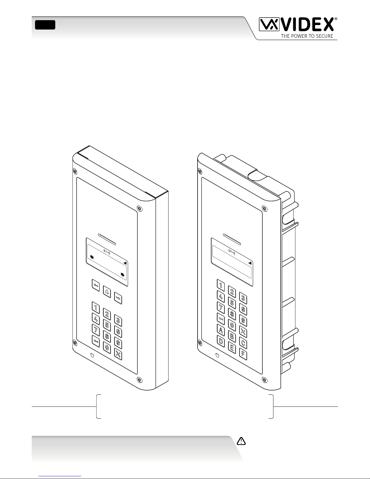
4000 Series Vandal Resistant Digital GSM Audio Intercom
with Proximity
66251750-EN
V1.0 - 05/06/17
We recommend
This equipment is installed by a
Competent Electrician, Security or
Communications Engineer.
Technical Manual
ENG
4812 / VR4812
4812R / VR4812R
Page 2
66251750-EN - V1.0 - 05/06/17
2
4000 Series Vandal Resistant Digital GSM - Technical Manual
4000 Series Vandal Resistant Digital GSM Audio Intercom with Proximity
EU RoHS DECLARATION OF CONFORMITY
Telit Communications certies that the GL865-QUAD V3 (Quad Band GSM850/EGSM900/DCS1800/PCS1900 GPRS Wireless
Module) is in conformity with Directive 2011/65/EU of the European Parliament and the Council of 8th June 2011 on the
restriction of the use of certain hazardous substances in electrical and electronic equipment. The conformity with the applicable
requirements of the Directive 2011/65/EU has been demonstrated against the following harmonized standard: EN 50581:2012
Technical Documentation for the assessment of electrical and electronic products with respect to the restriction of hazardous
substances.
WARNING!
To comply with FCC RF exposure requirements, a separation distance of 20cm (7.87”) or more
must be maintained between the antenna of this product and all persons.
Separate FCC approval for this product is not required as it will be classed as a xed installation.
THIS PRODUCT IS NOT DESIGNED TO BE USED AS AN EMERGENCY CALL POINT.
CUSTOMER SUPPORT
All Countries:
VIDEX ELECTRONICS S.P.A.
www.videx.it
technical@videx.it
Tel: +39 0734-631699
Fax: +39 0734-632475
CE conformity marking indicates that the product respects the requirements of the
applicable European Community Directives in force specically EMC 2004/108/
ECC, LVD 2006/95/ECC and CE-MARKING 93/68/ECC. CE marking is applied by the
manufacturer (or party delegated to do so by the manufacturer) under their own
responsibility. It was created to eliminate obstacles to the circulation of products
in European Union Member States by harmonising dierent national standards.
UK Customers:
VIDEX SECURITY LTD.
www.videxuk.com
tech@videxuk.com
Tech Line: 0191 224 3174
Fax: 0191 224 1559
Declaration of Conformity
Page 3
66251750-EN - V1.0 - 05/06/17
3
4000 Series Vandal Resistant Digital GSM - Technical Manual
4000 Series Vandal Resistant Digital GSM Audio Intercom with Proximity
Contents
Introduction .......................................................................................................................................................................................4
System Components and Available Versions ..................................................................................................................................6
Technical Information .......................................................................................................................................................................8
Additional Components ....................................................................................................................................................................9
Wiring Diagrams ............................................................................................................................................................................. 11
Auxiliary Input & Output ............................................................................................................................................................... 13
USB & RS485 Connection ............................................................................................................................................................... 15
General Directions for Installation ................................................................................................................................................ 17
Reset Procedure .............................................................................................................................................................................. 21
4000 Series Back Box Installation ................................................................................................................................................. 22
Programming via Alpha-Numeric Keypad .................................................................................................................................... 26
Programming Flowcharts .............................................................................................................................................................. 27
Programming Screens .................................................................................................................................................................... 36
Programming via Text Message .................................................................................................................................................... 45
System Operation ........................................................................................................................................................................... 61
User Commands .............................................................................................................................................................................. 63
Additional User Information .......................................................................................................................................................... 64
User Management .......................................................................................................................................................................... 66
Troubleshooting ............................................................................................................................................................................. 67
General Information ....................................................................................................................................................................... 69
Notes ................................................................................................................................................................................................ 70
Page 4
66251750-EN - V1.0 - 05/06/17
4
4000 Series Vandal Resistant Digital GSM - Technical Manual
4000 Series Vandal Resistant Digital GSM Audio Intercom with Proximity
Introduction
MANUAL INTRODUCTION
The information in this manual is intended as an installation and commissioning guide for the Digital GSM audio intercom system. This
manual should be read carefully before the installation commences. Any damage caused to the equipment due to faulty installation
where the information in this manual has not been followed is not the responsibility of Videx Security Ltd.
It is recommended that the Digital GSM audio intercom is installed by a competent electrician, security or communications engineer.
For UK customers Videx run free training courses for engineers who are unfamilier or who have not installed this system before. Technical
help is also available on tel: 0191 224 3174 during oce hours (8:30am - 5:00pm MON to FRI) or via e-mail: tech@videxuk.com.
A copy of this Technical Manual can also be downloaded from the Videx website: www.videxuk.com, www.videx.it.
SYSTEM INTRODUCTION
The vandal resistant digital GSM is designed to work on the same technology as mobile phones. It enables a call to be made from
an entry point (door, gate etc), to any telephone number (mobile or land line). Up to 500 users can be programmed into the door
panel, each able to call up to four telephone numbers (if the primary number is busy or not answered, the call can be diverted
through to up to three dierent divert numbers).
Key features of the system include:
• Vandal resistant brushed stainless steel (2mm thick) front panel.
• Blue back-lit alpha-numeric keypad (for system operation and programming).
• Blue back-lit 128x64 pixel graphical LCD display.
• Speech annunciation.
• Micro-USB connection (for ease of programming using the GSMSK PC software).
• A dry contact relay.
• A switched 0V auxiliary input (AI).
• An open collector auxiliary output (AO).
• Push to exit input.
• Trade input.
• RS485 connection (for ease of programming using the GSMSK PC software).
• Proximity fobs/cards for up to 2000 users.
• DTO (dial to open) facility for up to 2000 numbers.
• 500 programmable users (each with 4 numbers, 1 primary and 3 diverts).
• 500 programmable door access codes (1 code per user).
• 10 timebands (9 of which are programmable).
• Event log for 8000 events.
IMPORTANT NOTE: Although all the features and general installation instructions mentioned in this technical manual make
reference to the Art.4812 and Art.4812R digital GSM intercoms the same features and instructions can also be applied when
installing the VR4812 and VR4812R digital GSM intercoms.
SIM CARD SELECTION
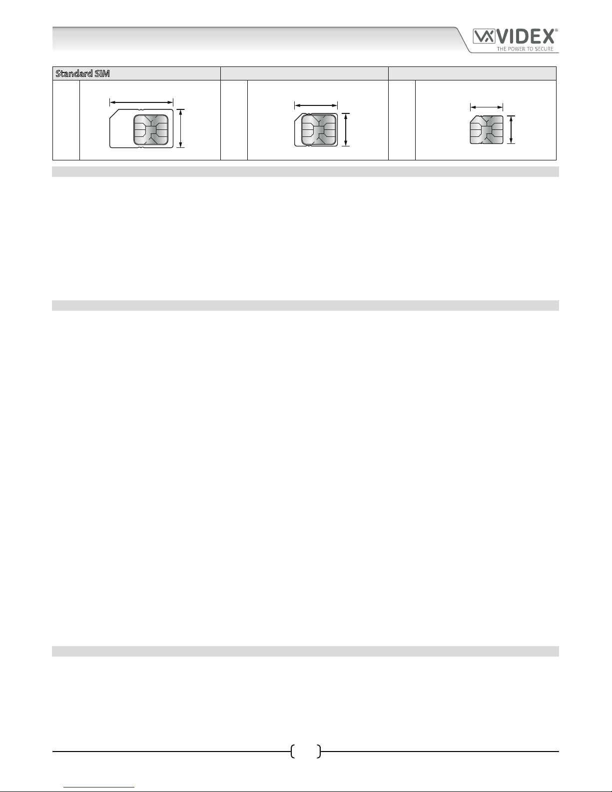
A SIM card is required for this product but not supplied by Videx. The digital GSM intercom can only accept a standard size SIM
card (refer to the following SIM card size chart), both a micro-SIM and nano-SIM are not suitable. It is recommended to choose the
SIM card which has the best coverage for the area in which the intercom panel will be installed. Both contract and ‘Pay as you go’
SIM cards can be used, however if using a ‘Pay as you go’ we would recommend setting up an automatic top up to avoid running
short on credit and losing the use of the intercom panel. Alternatively if you already have a contract mobile phone it should be
possible to get a second SIM card and telephone number on the existing account. For more information contact the SIM card
provider or visit their web sites.
Page 5
66251750-EN - V1.0 - 05/06/17
5
4000 Series Vandal Resistant Digital GSM - Technical Manual
4000 Series Vandal Resistant Digital GSM Audio Intercom with Proximity
Standard SIM Micro-SIM Nano-SIM
;
25mm
15mm
:
15mm
12mm
:
12.3mm
8.8mm
NETWORK PROVIDER SELECTION
It is imperative that for the reliable operation of the system that the best network provider for the area is selected. Problems such as
network disconnection can occur if the provider has signal or interference problems for that area. We would recommend using a GSM
signal strength meter to survey the intended antenna location. Contact Videx for more information on where to purchase a tester.
For UK customers, as an initial check we also recommend visiting the ofcom website www.ofcom.org.uk and follow the onsite links to
their online mobile coverage tool. This tool will advise on the best coverage for the main network providers and other general queries
that you may have about the service provider.
For customers from other countries we suggest consulting the website of the network provider that will be used to check the coverage.
The antenna should always be mounted vertically at the highest point possible. Metal structures and sources of interference such as
power cables, control panels etc. can aect signals and so the antenna should be mounted away from these.
PRECAUTIONARY ADVICE
• When mounting the GSM antenna, choose a location which is away from human interaction and away from the intercom panel.
Route the GSM antenna cable from the intercom panel so that it is separate from the power supply cables and microphone wire.
• Always ensure the power is switched OFF to the intercom panel before inserting or removing the SIM card.
• New SIM cards will need registering with the network service provider before they can be used. Full details of how this is done
can normally be found in the SIM card pack. It will normally require that the SIM card is inserted into a mobile phone, a number
dialled and instructions followed. While the SIM is in the mobile phone it would be a good time to disable any PIN codes, call
diverts, ring back and disable features such as voicemail and text alerts. Details of how to do this can be found on the SIM card
provider’s web site or by calling their customer services. Recommended SIM card providers are: Vodafone, T-Mobile, O2 or
Orange/EE. We do not recommend using the 3 network at this present time.
• To be able to receive text messages from the intercom panel, the SIM card will require an SMS service centre number. This is
normally preinstalled on new SIM cards but if you are having trouble receiving SMS messages you will need to conrm this by
inserting the SIM card into a mobile phone and using the phones menu options to check it. If a number is not programmed then
it should be programmed while in the phone (the number can be obtained from the network service provider).
• Voicemail and text alerts must be switched OFF on the SIM card when using the dial in to release the door/gate feature. For
Vodafone and O2 this can be done while the SIM card is in the intercom panel. For Orange/EE, T-Mobile and other providers the
SIM card must be removed from the intercom panel, inserted into a mobile phone and the mobile phone menu instructions
followed.
• When storing the intercom panel’s telephone number in your own mobile phone avoid using an obvious name such as ‘Front
Door, or ‘My Gate’ as this would make it easy to decipher if your phone was lost or stolen.
• The PIN request feature must be disabled on the SIM card before using it in the Intercom panel. It is likely on a new SIM card that
it will not be enabled but if it is, it will prevent the system from working at all.
• This product may not be suitable for installation in hospitals, health care facilities or in the presence of ammable gases or
liquids. Seek advice and authorisation before installing this product in these locations. This product is not designed to be used
as an emergency call point.
Network provider and services conguration codes mentioned in this manual are specic for the UK. Please contact the network provider
of your country for the corresponding codes.
IMPORTANT NOTE ABOUT THE SIM
When using a pay monthly SIM card you must ask the service provider to put a spend limit (credit limit) on the account (Vodafone
call this service ‘spend checker’). This is to safeguard against possible problems which could result in a large phone bill at the end of
the month. All providers oer this service. You will need to either ring them or e-mail them to set this up. Automatic top ups should
also have a monthly limit. We would suggest a limit of £50.00 which should be more than enough. This service is not provided by
Videx.
Introduction
Page 6

66251750-EN - V1.0 - 05/06/17
6
4000 Series Vandal Resistant Digital GSM - Technical Manual
4000 Series Vandal Resistant Digital GSM Audio Intercom with Proximity
DESCRIPTION
The 4000 series vandal resistant (front plate in brushed stainless steel with 2mm thickness) digital GSM is designed to work on the
same technology as mobile phones. The panel is compatible with the vandal resistant 4000 series modular range and is the size
of two 4000 series modules. It enables a call to be made from an entry point (door, gate etc), to any telephone number (mobile or
land line). Up to 500 users can be programmed into the door panel, each able to call up to four telephone numbers (if the primary
number is busy or not answered, the call can be diverted through to up to three dierent divert numbers).
Additionally, each user can have a unique access code up to 6 digits, an apartment number up to 6 digits, their numbers added to
the ‘DTO’ dial to open list (to allow them to dial into the panel and release the door/gate), a timeband facility to restrict when an
apartment can receive calls (up to 10 timebands are available 9 of which can be programmed). On the scroll panel version a user
name option is available with up to 16 characters.
Also, integrated into the panel is a proximity reader enabling up to 2000 user fobs/cards to be stored and used individually or in
combination with the access code. In addition the panel includes a 128x64 pixel graphical LCD display with blue back light that
provides both text and graphical messages guiding a user through the panel programming and operation. The LCD graphical
display can also be used to display a company logo or name which can switch between the panel’s standard (or customised)
welcome message and the logo.
AVAILABLE VERSIONS
Two optional panels are available the Art.4812 (VR4812) and the Art.4812R (VR4812R) each with an integrated programmable
keypad. The Art.4812 has 18 back lit buttons, 6 of which are alpha buttons (A - F), 10 are numeric buttons (0 - 9), plus an “ENTER”
and a “CLEAR” button. The Art.4812R has 15 back lit buttons, 10 are numeric buttons (0 - 9), plus an “ENTER” and “CLEAR”
button with a “CALL”
and two “SEARCH” buttons , . To compliment the visual messages provided by the display, the
panel has a voice annunciation facility to supply audio messages concerning the system operation.
The onboard programming menu and setup menu are protected by two access codes with dierent login levels:
The master code: this code grants full access to all the programming functions (default ‘1111’):
1. Apartment menu - allows the programming of the apartment details, e.g. apartment name/numbers, telephone
numbers etc.
2. Proximity menu - allows the programming of proximity fobs/cards.
3. General settings menu - allows the general set up of the digital GSM, e.g. the panel’s volume controls, proximity
reader enabling etc.
4. Code settings menu - allows the programming of the master code, admin code and trade code.
5. Time settings menu - allows the set up and programming of the digital GSM’s time settings, e.g. call time, diver time,
relay time and timebands etc.
The admin code: this code is limited to only specic programming functions (default ‘0000’):
1. Apartment menu - allows the programming of the apartment details, e.g. apartment name/numbers, telephone
numbers etc.
2. Proximity menu - allows the programming of proximity fobs/cards.
Programming of the telephone numbers and the additional features, including programming key fobs for the integrated proximity
access, can be carried out either using the alpha-numeric keypad on the front of the panel via graphical menus, text messaging
(refer to pages 45 to 59) or by using the GSMSK PC software (refer to the GSMSK PC software manual).
System Components and Available Versions
Page 7

66251750-EN - V1.0 - 05/06/17
7
18/11/16 08:35
Or Search
Enter Number
18/11/16 08:35
Enter Number
103mm
240mm
%0
A
B
GND
12V
0V
PTE
AI
TRD
AO
NC
CO
NO
USB
4812
4812R
RS485
Vandal Resistant 4000 Series Digital GSM Panel
%0
A
B
GND
12V
0V
PTE
AI
TRD
AO
NC
CO
NO
USB
RS485
4000 Series Vandal Resistant Digital GSM - Technical Manual
4000 Series Vandal Resistant Digital GSM Audio Intercom with Proximity
ART. 4812 DIGITAL FRONT PANEL
System Components and Available Versions
Art. 4812 / VR4812 Art. 4812R / VR4812R
Speaker
Display
Keypad
Proximity Reader
Fig. 1 - Front View
Fig. 2 - Rear View
RS485
bus connection terminals
Connection terminals
SMA antenna connection
Speaker
volume adjustment switches
micro-USB connection
SIM card holder
Page 8
66251750-EN - V1.0 - 05/06/17
8
4000 Series Vandal Resistant Digital GSM - Technical Manual
4000 Series Vandal Resistant Digital GSM Audio Intercom with Proximity
Technical Information
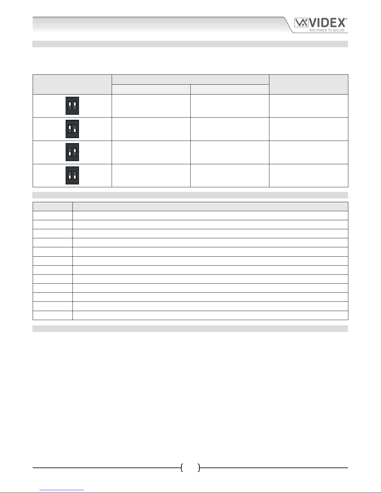
SPEAKER VOLUME ADJUSTMENT DIPSWITCH SETTINGS
There are 2 dip-switches located on the back of the digital GSM module next to the SIM card holder. They can be used to adjust the
volume from the door intercom speaker (see table below). Additionally, the volume can also be adjusted during a call electronically
via the telephone keypad (refer to user command table 1 on page 62).
Dip-Switch
Dip-Switch Status
Gain (dB)
Dip No.1 Dip No.2
12
ON
ON ON 6
12
ON
ON OFF 12
12
ON
OFF ON 18
12
ON
OFF OFF 23.5
TERMINAL CONNECTIONS
Terminal Description
A RS485 A connection.
B RS485 B connection.
GND RS485 ground connection.
12V +12Vdc power (500mA max.).
0V 0V ground power.
PTE Push to exit input (switched 0V).
AI Auxiliary input.
TRD Trade input.
AO Auxiliary output.
NC Normally closed relay connection.
CO Common relay connection.
NO Normally open relay connection.
TECHNICAL SPECIFICATION
Working Voltage : 12Vdc +/- 10%
Standby Current : 60mA (max.)
Max. Current : 500mA (max.)
No. of Users : up to 500 (max.)
Telephone Numbers (per apartment) : 4 telephone numbers (1 primary, 3 diverts)
Dial to Open Numbers : up to 2000 (max.)
Proximity Access (fobs/cards) : up to 2000 (max.)
Door/Gate Access Codes : up to 500 (max., 1 per user)
Timebands : 10 (1 preset, 9 programmable)
Programming : via alpha-numeric keypad, SMS messaging or PC software
Push to Exit : 1 (switched 0V input)
Auxiliary Input : 1 (switched 0V input)
Auxiliary Output : 1 (open collector output, switched 0V, 150mA max.)
Dry Contact Relay : 3A @ 24Vdc, 3A @ 120Vac
Event Log : up to 8000 events
USB port : micro USB
RS485 connection : 1 (A, B and GND)
Working Temp. : -10 +50°C
Page 9

66251750-EN - V1.0 - 05/06/17
9
4000 Series Vandal Resistant Digital GSM - Technical Manual
4000 Series Vandal Resistant Digital GSM Audio Intercom with Proximity
Additional Components
Apart from the requirement of a SIM card additional parts will be required for the successful installation of the digital GSM. The
following components will also be required:
4000 SERIES BACK BOXES AND MOUNTING FRAMES
Both the Art.4812 and Art.4812R are designed to t the 4000 series range of back boxes and frames, both surface and ush back
boxes and mounting frames are available. The digital GSM requires a 2 module back box and frame. Front support frames are
available in a gun metal grey nish, chrome nish (sux \C to the frame code) or gold nish (sux \G to the frame code). The
following surface (see Fig.3) and ush (see Fig.4) options are available.
Fig. 3 Fig. 4
Surface Back Box Dimensions
Part No. Housed Modules No. of Columns Back Box (W x H x D) mm
Art.4882 2 1 135 x 280.2 x 43
Flush Back Box Dimensions
Part No. Housed Modules Front Frame (W x H x D) mm Back Box (W x H x D) mm
Art.4852 2 135 x 280.2 x 15.7 120 x 263.2 x 46
12VDC 2A POWER SUPPLY
The digital GSM intercom is designed to work with power supplies in the range
of 12Vdc to 14Vdc and should be capable of supplying a constant current of no
less than 2A. Typically the digital GSM can use a 12Vdc 2A power supply (refer
to Fig.5).
Fig. 5
Page 10

66251750-EN - V1.0 - 05/06/17
10
4000 Series Vandal Resistant Digital GSM - Technical Manual
4000 Series Vandal Resistant Digital GSM Audio Intercom with Proximity
Additional Components
ART. 432 GSM ANTENNA
The digital GSM also requires an antenna to function, the Art.432 GSM antenna
connects to the SMA female bulkhead connection on the rear of the digital GSM
module. A GSM antenna with an SMA male connector should be used (refer to
Fig.6).
Antenna Parts
1. GSM antenna with magnetic base.
2. Self-threading screw (Ø3.5mm x 9.5mm).
3. Aluminium L bracket for mounting.
4. SMA male connector (cable length 2.5m).
5. Expansion type wall plugs (Ø6mm).
6. Self-threading screw (Ø4mm x 30mm).
IMPORTANT NOTE: An antenna must always be tted for the digital GSM module
to work. Always route the GSM antenna cable away from the microphone wires
and the power supply wires to avoid interference on the speech channels.
Fig. 6
SMA female bulkhead
connection on rear of
digital GSM module
Page 11
66251750-EN - V1.0 - 05/06/17
11
4000 Series Digital GSM - Technical Manual
4000 Series Digital GSM Audio Intercom with Proximity
Wiring Diagrams
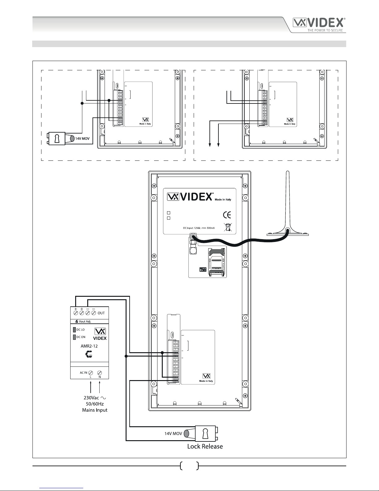
LOCK RELEASE AND VOLT FREE CONNECTIONS
Fig.7 below shows connections for a fail secure and a fail safe lock release and also volt free contacts.
%0
A
B
GND
12V
0V
PTE
AI
TRD
AO
NC
CO
NO
USB
RS485
Fail Safe
Lock Release
+12Vdc
0V
Fail Safe
Lock Release
%0
A
B
GND
12V
0V
PTE
AI
TRD
AO
NC
CO
NO
USB
RS485
Volt Free
Contacts
+12Vdc
0V
%0
A
B
GND
12V
0V
PTE
AI
TRD
AO
NC
CO
NO
USB
4812
4812R
RS485
Vandal Resistant 4000 Series Digital GSM Panel
Fig. 7
Page 12
66251750-EN - V1.0 - 05/06/17
12
4000 Series Digital GSM - Technical Manual
4000 Series Digital GSM Audio Intercom with Proximity
Wiring Diagrams
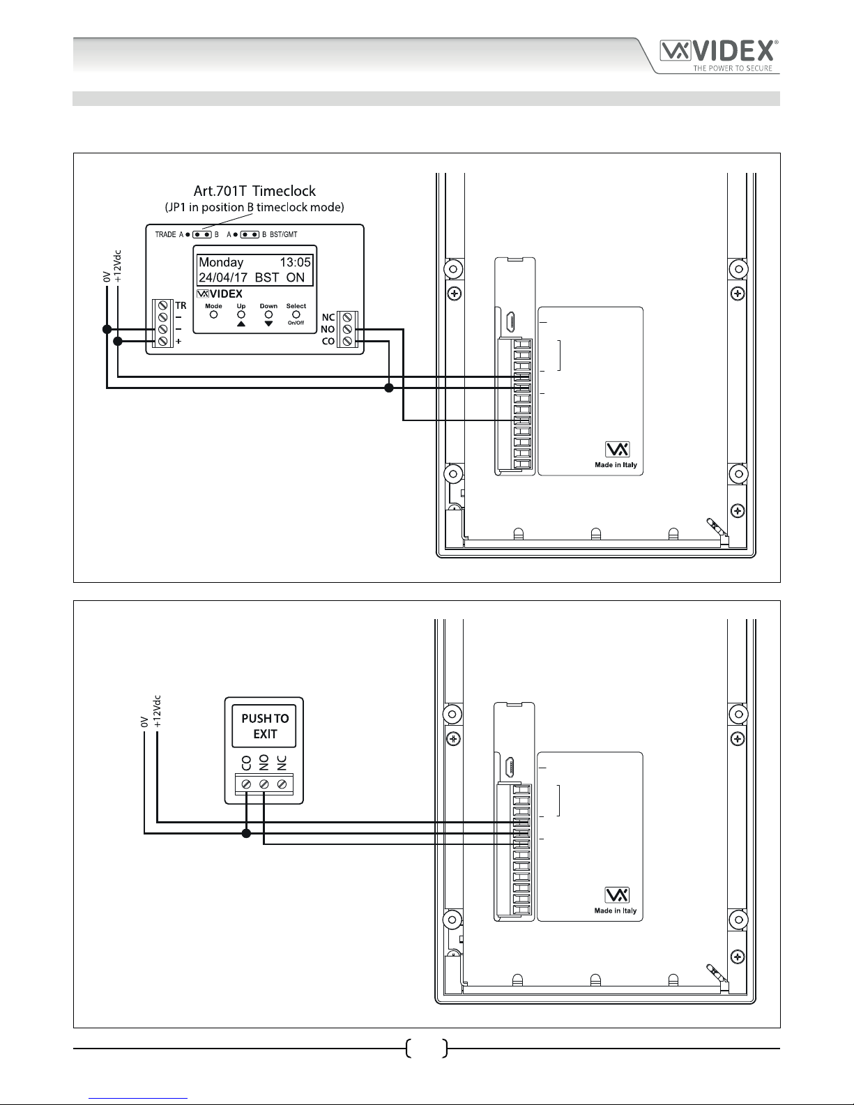
TRADE INPUT AND PUSH TO EXIT INPUT CONNECTIONS
Fig.8 below shows connections for the trade input using an Art.701T timeclock (in timeclock mode) and Fig.9 shows connections
for the push to exit input using a push-to-make (normally open going closed) switch/button.
%0
A
B
GND
12V
0V
PTE
AI
TRD
AO
NC
CO
NO
USB
RS485
Fig. 8
%0
A
B
GND
12V
0V
PTE
AI
TRD
AO
NC
CO
NO
USB
RS485
Fig. 9
Page 13
66251750-EN - V1.0 - 05/06/17
13
4000 Series Digital GSM - Technical Manual
4000 Series Digital GSM Audio Intercom with Proximity
Auxiliary Input & Output
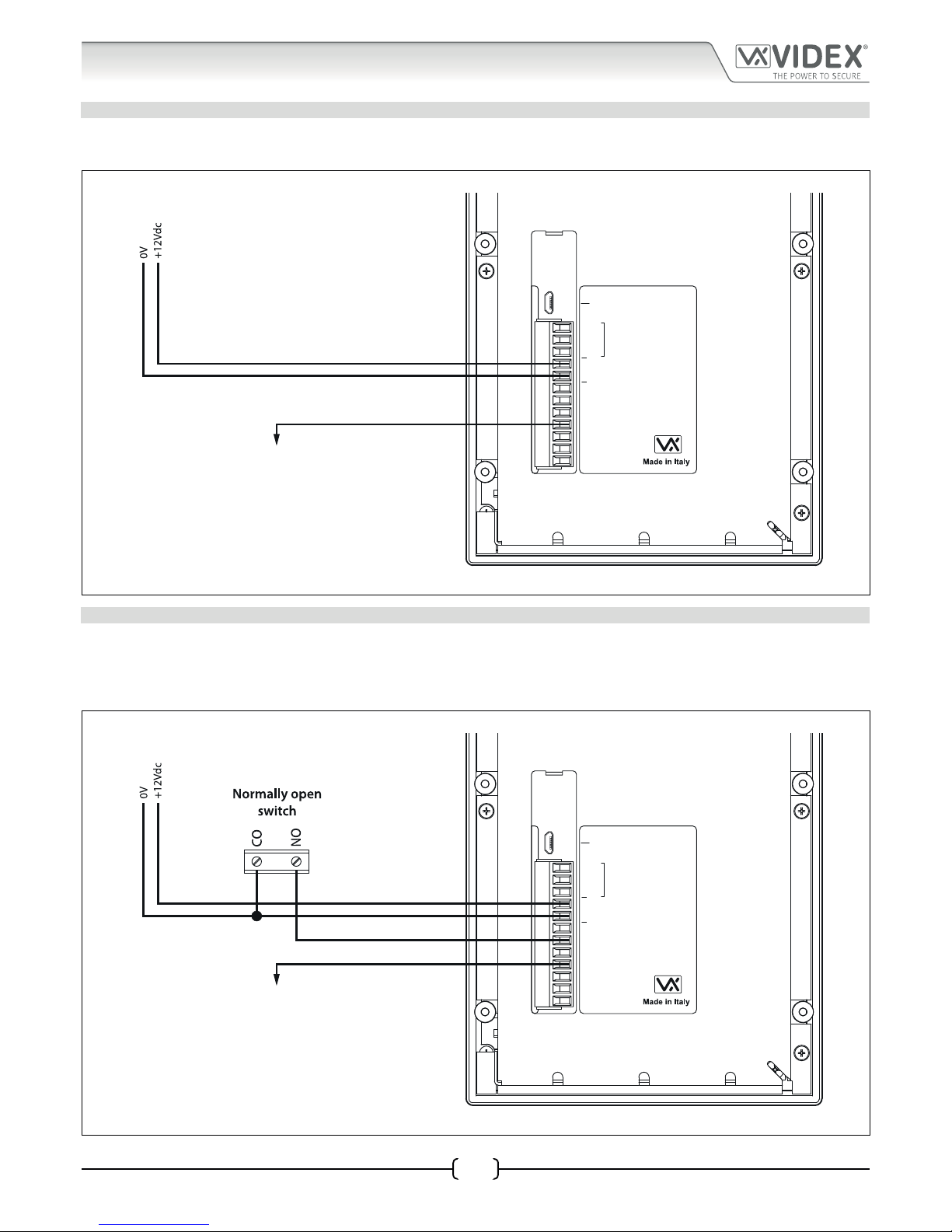
AUXILIARY OUTPUT AO WHEN SET TO MODE 000 ON DURING A CALL
Fig.10 below shows the connection for auxiliary output AO when the AOM mode is set to 000. The auxiliary output AO will activate
once a call to an apartment has been made and will stay activated for the duration of the call.
%0
A
B
GND
12V
0V
PTE
AI
TRD
AO
NC
CO
NO
USB
RS485
When the auxiliary output mode (AOM) is set to mode 000.
The auxiliary output AO will activate from when a call is made
to an apartment and stay activated for the duration of the call.
When the call is nished the auxiliary output AO will
deactivate.
Fig. 10
AUXILIARY INPUT AI AND AUXILIARY OUTPUT AO WHEN SET TO MODE 001 ON WHEN TRIGGERED
Fig.11 below shows the connection for auxiliary output AO when the AOM mode is set to 001. The auxiliary output AO can be
activated remotely by the user sending the text message 1111 A1O to the digital GSM intercom or by pressing 6 on the telephone
during a call and will stay activated for the programmed auxiliary output time A1T. The auxiliary output can also be triggered by a
normally open switch (switched 0V) connected into the auxiliary input AI.
%0
A
B
GND
12V
0V
PTE
AI
TRD
AO
NC
CO
NO
USB
RS485
The auxiliary output AO will activate for the programmed
auxiliary output time (A1T) when the auxiliary input AI is
triggered from a normally open switch (switched 0V) and the
auxiliary output mode (AOM) is set to mode 001.
The auxiliary output AO can also be triggered remotely by
sending the text message 1111A1O to the digital GSM or by
pressing 6 on the telephone during a call.
Fig. 11
Page 14

66251750-EN - V1.0 - 05/06/17
14
4000 Series Digital GSM - Technical Manual
4000 Series Digital GSM Audio Intercom with Proximity
Auxiliary Input & Output
AUXILIARY OUTPUT AO WHEN SET TO MODE 002 CALL ACTIVATED
Fig.12 below shows the connection for auxiliary output AO when the AOM mode is set to 002. The auxiliary output AO will activate
once a call to an apartment has been made and will stay activated for the programmed auxiliary output time A1T.
%0
A
B
GND
12V
0V
PTE
AI
TRD
AO
NC
CO
NO
USB
RS485
When the auxiliary output mode (AOM) is set to mode 002.
The auxiliary output AO will activate from when a call is made
to an apartment and stay activated for the auxiliary output
time (A1T).
Fig. 12
CONNECTING A SECONDARY DEVICE TO THE AUXILIARY OUTPUT AO
Since the auxiliary output AO is a transistor switched output (switched low output) it can be connected to a relay (e.g. an Art.506N).
This is particularly useful if a secondary device requires triggering. Fig.13 shows how to connect an Art.506N relay.
%0
A
B
GND
12V
0V
PTE
AI
TRD
AO
NC
CO
NO
USB
RS485
Fig. 13
Page 15

66251750-EN - V1.0 - 05/06/17
15
4000 Series Digital GSM - Technical Manual
4000 Series Digital GSM Audio Intercom with Proximity
USB & RS485 Connection
CONNECTIONS TO A PC
The digital GSM intercom also includes two options for connecting to a PC: via a USB connection or via an RS485 connection. Both
methods of connection are to allow for ease of programming and monitoring using the GSMSK PC software. All programming
features described in this manual are also accessible using the software. Further information on using the GSMSK PC software can
be found in the technical manual GSMSK-PC-SOFTWARE-MANUAL-ENUK-V1-2 (or later version).
OPTION 1: USB CONNECTION
The digital GSM can be connected using a standard micro-USB to USB cable as shown in Fig.14. This method of connection is
primarily used for programming and setup of the digital GSM panel.
%0
A
B
GND
12V
0V
PTE
AI
TRD
AO
NC
CO
NO
USB
4812
4812R
RS485
Vandal Resistant 4000 Series Digital GSM Panel
PC
USB cable
Fig. 14
Page 16
66251750-EN - V1.0 - 05/06/17
16
4000 Series Digital GSM - Technical Manual
4000 Series Digital GSM Audio Intercom with Proximity
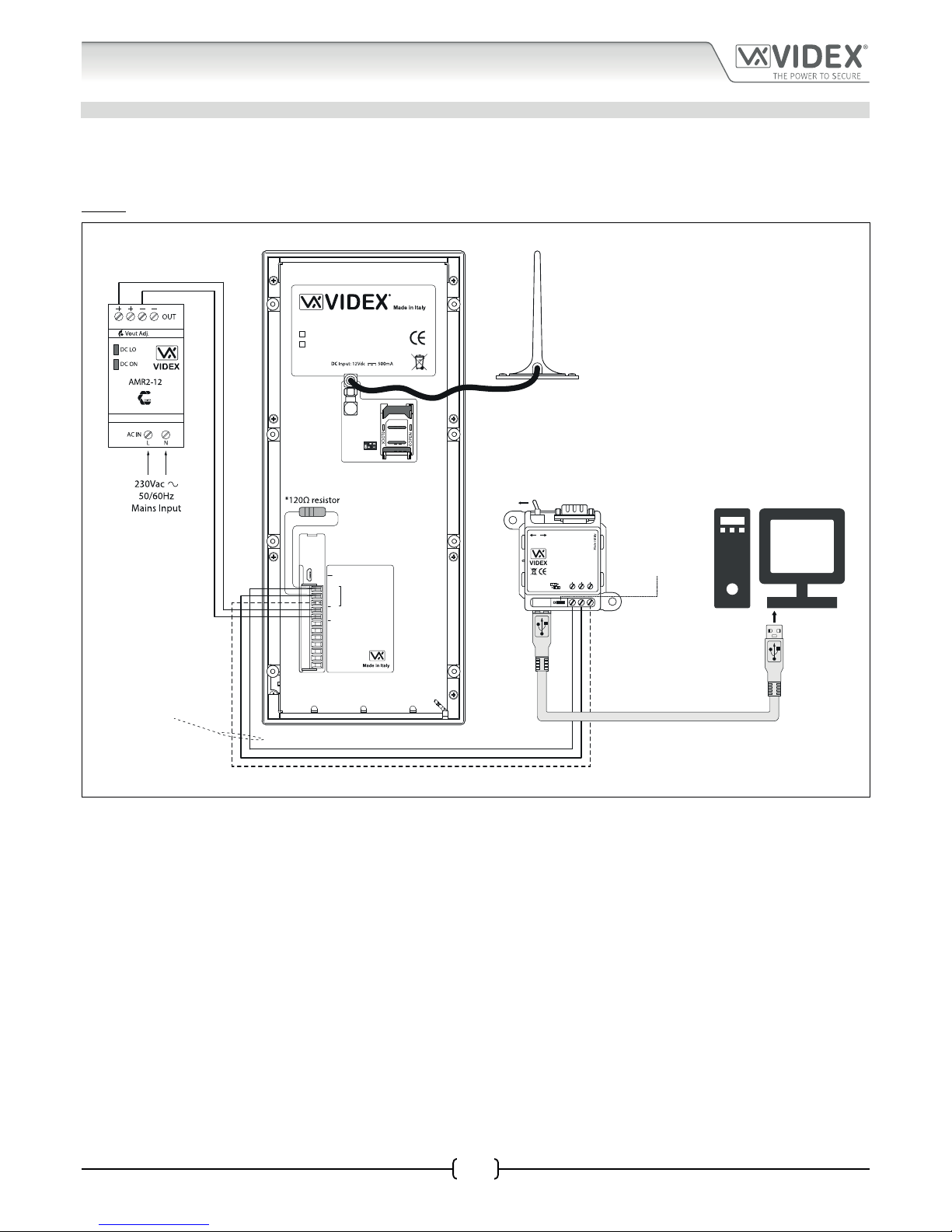
OPTION 2: RS485 CONNECTION
The digital GSM intercom can also be connected using an RS485 bus connection via an RS485 to USB converter (Art.481) as shown
in Fig.15. This method of connection, like option 1, can be used for programming and setup of the digital GSM, but can also be
used in instances where a permanent connection to a PC is required for monitoring purposes and downloading event logs. When
connected in this way the digital GSM can only be connected as a ‘one-to-one’ bus connection to the PC, another GSM module
cannot be connected on the same RS485 bus to the PC.
%0
A
B
GND
12V
0V
PTE
AI
TRD
AO
NC
CO
NO
USB
4812
4812R
RS485
Vandal Resistant 4000 Series Digital GSM Panel
485 / 232
RS-485
USB-PC
A B GND
RS-232
Art. 481
USB-Serial Converter
Open
Close
BUS
Termination
PC
USB cable
RS485 cable
switch to RS485 position
BUS termination
jumper in the
closed position
Fig. 15
*For end of line termination a 120 Ohm resistor must be tted across the RS485 terminals A and B, as shown in Fig.15.
USB & RS485 Connection
Page 17
66251750-EN - V1.0 - 05/06/17
17
4000 Series Vandal Resistant Digital GSM - Technical Manual
4000 Series Vandal Resistant Digital GSM Audio Intercom with Proximity
CABLE SIZE GUIDE
Refer to the table below for the connections for the power supply output to the Art.4812/Art.4812R digital GSM intercom and the
lock release connections.
Distance 20m 50m 100m
Cross Sectional Area (CSA) 0.5mm
2
1.0mm
2
1.5mm
2
Ideally the power supply should be located as close to the intercom panel as possible for best performance. The maximum
acceptable resistance for the above cables = 3Ω or less for best possible performance.
IMPORTANT NOTE: Only bare copper (BC) cable should be used (solid or stranded is acceptable). Please be aware that when
selecting a cable the following should NOT be used: Copper Coated Steel (CCS) and Copper Clad Aluminium (CCA). While these
types of cable may oer a low cost solution they will have a higher resistance than pure copper cable and can aect the overall
performance of the system therefore Videx DO NOT recommend these types of cable.
GENERAL INSTALLATION NOTES
• Check that all components are free from damage before installing (do not proceed with installation in the event of damage).
• Keep all packaging away from children.
• Do not obstruct the ventilation openings or slots on any of the devices.
• All connections to mains voltages must be made to the current national standards (I.E.E. wiring regulations or the
appropriate standards of your country).
• Install an appropriate fused spur or isolation switch to isolate the mains.
• Isolate the mains before carrying out any maintenance work on the system.
• Avoid water ingress into the rear of the module, always seal the module frame after installation using a suitable silicon
based sealant.
• All intercom and access control cables must be routed separately from the mains.
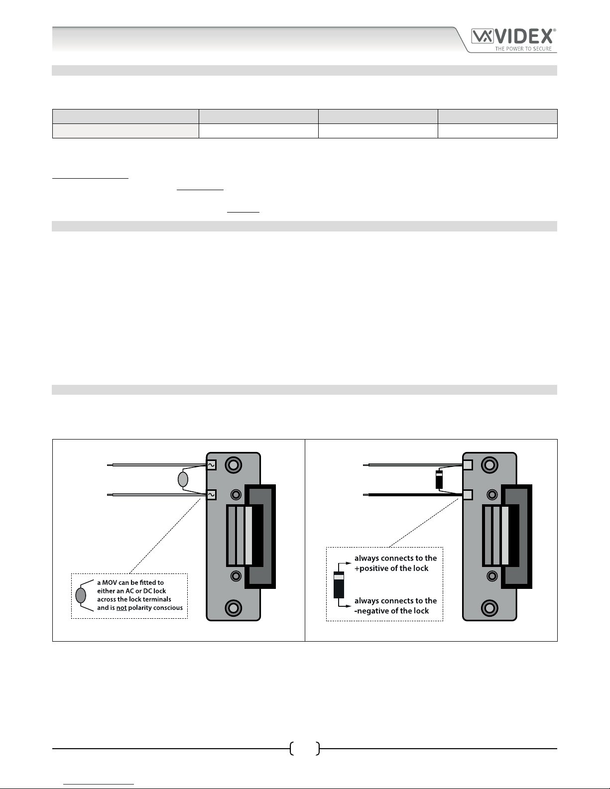
LOCK RELEASE WIRING AND BACK EMF PROTECTION
When tting an electric lock release back EMF protection will be required. If tting an AC lock release then a 100nF ceramic disc
capacitor must be tted across the terminals of the lock, shown in Fig.16. If tting a DC lock release (fail secure or fail safe) then a
1N4002 diode must be tted across the terminals on the lock, shown in Fig.17.
100nF CAP
+
-
1N4002 DIODE
Fig. 16 Fig. 17
If a 100nF ceramic disc capacitor or a 1N4002 diode are not available then a 14 - 20V MOV (metal oxide varistor) can be tted across
the lock terminals instead (refer to Fig.16 above) and can be tted on both an AC and DC lock. Connection examples can also be
seen on the wiring diagrams on page 11.
General Directions for Installation
Page 18
66251750-EN - V1.0 - 05/06/17
18
4000 Series Vandal Resistant Digital GSM - Technical Manual
4000 Series Vandal Resistant Digital GSM Audio Intercom with Proximity
General Directions for Installation
CONNECTION TO MAINS, SAFETY AND GUIDANCE NOTES
IMPORTANT: PLEASE READ THESE INSTRUCTIONS CAREFULLY BEFORE COMMENCING WITH THE INSTALLATION.
Videx recommends that any cabling and Videx product be installed by a competent and qualied electrician, security installation
speclialist or communications engineer.
• DO NOT install any Videx product in areas where the following may be present or occur:
• Excessive oil or a grease laden atmosphere.
• Corrosive or ammable gases, liquids or vapours.
• Possible obstructions which would prevent or hinder the access and/or removal of the Videx product.
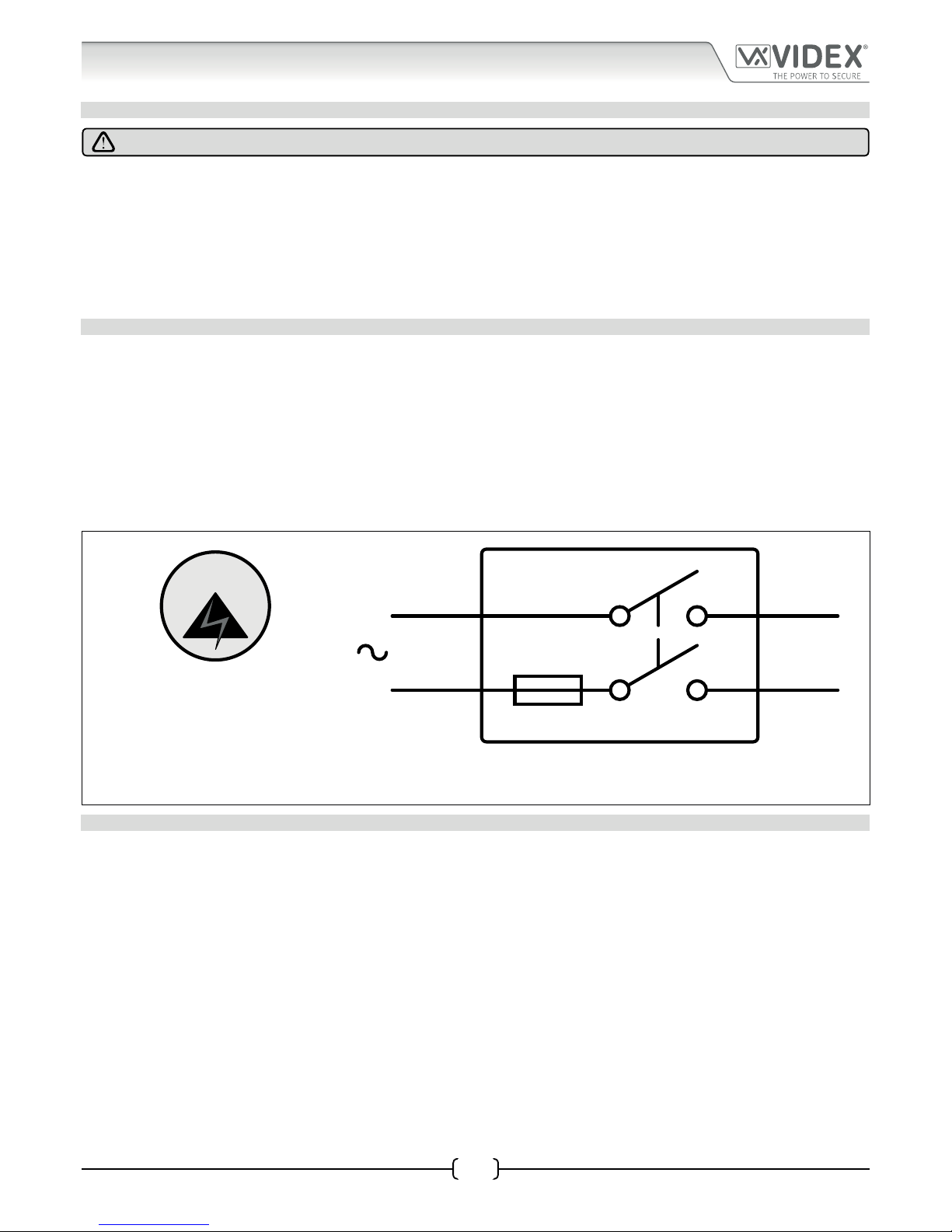
MAINS CONNECTION
The system MUST be installed in accordance with the current I.E.E regulations (in particular I.E.E. Wiring regulations BS7671), or the
appropriate standards of your country, in particular Videx recommends:
• Connecting the system to the mains through an all-pole circuit breaker (refer to Fig.18) which shall have contact separation
of at least 3mm in each pole and shall disconnect all poles simultaneously.
• That the all-pole circuit breaker shall be placed in such a way to allow for easy access and the switch shall remain readily
operable.
• Ensuring that the mains supply ( Voltage, Frequency and Phase) complies with the product rating label.
• Isolating the mains before carrying out any maintenance work on the system.
FUSE
N
L
Mains
1 PHASE SUPPLY
(220 - 240Vac, 50/60Hz)
SWITCHED FUSE SPUR
Fig. 18
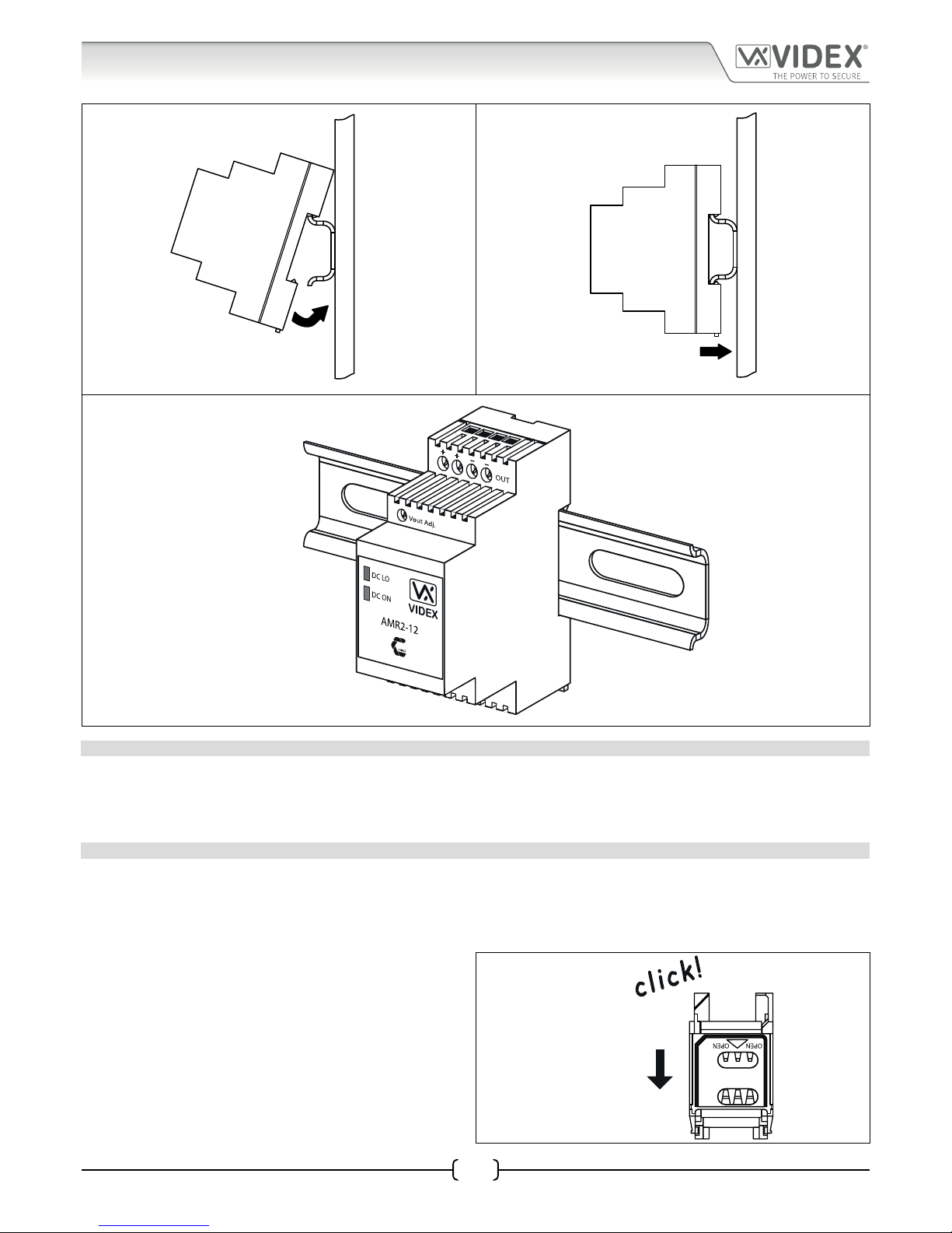
POWER SUPPLY INSTALLATION
Follow the steps below when tting the 12Vdc 2A power supply.
• First remove the terminal side covers by unscrewing the retaining screws.
• Fix the power supply to a DIN rail (following Fig.19, Fig.20 and Fig.21).
• Switch OFF the mains using the circuit breaker (mentioned previously) and then make the connections as shown on the
installation diagrams.
• Check the connections and secure the wires into the terminals ensuring that the low voltage (signal) cables are routed
separately from the high voltage (mains) cables.
• Replace the terminal covers and x them back into place using the relevant screws.
• When all connections are made restore the mains supply.
Page 19
66251750-EN - V1.0 - 05/06/17
19
4000 Series Vandal Resistant Digital GSM - Technical Manual
4000 Series Vandal Resistant Digital GSM Audio Intercom with Proximity
Fig. 19 Fig. 20
Fig. 21
PANEL CARE
The digital GSM panel facia is brushed stainless steel. It is important that the facia is cleaned on regular occasions to prevent dirt
build up and tarnishing of the metal. A general household metal polish can be used but care should be taken to follow the grain
of the metal when polishing and also avoid any polish build up around the panel buttons which may prevent the buttons from
operating correctly.
FITTING A SIM CARD
After connecting the power supply, antenna, lock output and any auxiliary devices as shown in this manual and before powering
up, a SIM card must be installed (the SIM must already be registered with the network provider). The SIM holder can be found on the
back of the module next to the SMA antenna connection. A SIM card from most network providers can be used with the exception
of the 3 network. Follow the steps below to insert the SIM card:
1. First slide the SIM holder on the back of the digital GSM
module down until it ‘clicks’, as shown in Fig.22.
Fig. 22
General Directions for Installation
Page 20
66251750-EN - V1.0 - 05/06/17
20
4000 Series Vandal Resistant Digital GSM - Technical Manual
4000 Series Vandal Resistant Digital GSM Audio Intercom with Proximity
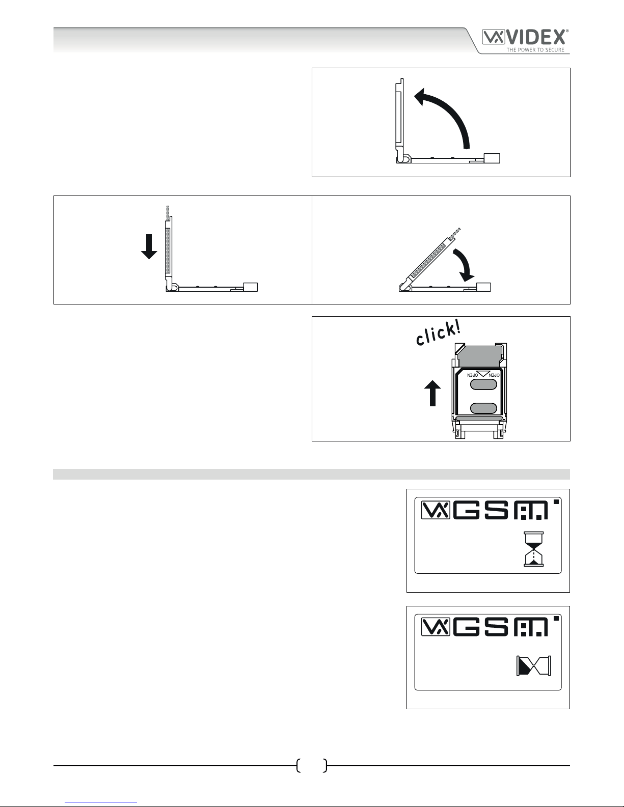
2. The SIM holder is hinged and will open out, see Fig.23.
Fig. 23
3. Place the SIM card into the holder (it will only t one way, see Fig.24) and fold the holder back down, see Fig.25.
Fig. 24 Fig. 25
4. Slide the SIM holder back up until it ‘clicks’, see Fig.26.
Fig. 26
5. Once the SIM is in place follow the initialisation process.
POWER UP INITIALISATION SEQUENCE
The digital GSM intercom requires approximately 25 - 30 seconds too initialise properly.
We recommend NOT sending any SMS messages or pressing buttons during this time.
1. First check all the connections have been made correctly and then power up the
system.
2. The graphical display and the keypad buttons will illuminate.
3. After approximately 5 seconds the display will show the Videx GSM logo and
current rmware version number, as shown in Fig.27.
4. After a further 10 seconds the GSM will emit a beep and below the Videx logo it
will indicate the digital GSM is registering with the network, as shown in Fig.28.
5. After a further delay the display will then show the default welcome screen (refer
to Fig.100 for the Art.4812 and Fig.101 for the Art.4812R on page 61).
Fig. 27
Fig. 28
PLEASE WAIT...
VER DG4.0.0
VIDEX
PLEASE WAIT...
REGISTERING...
VIDEX
General Directions for Installation
Page 21
66251750-EN - V1.0 - 05/06/17
21
4000 Series Vandal Resistant Digital GSM - Technical Manual
4000 Series Vandal Resistant Digital GSM Audio Intercom with Proximity
Reset Procedure
RESETTING THE DIGITAL GSM INTERCOM TO FACTORY DEFAULTS
There are two reset procedures for the digital GSM panel. The rst will reset the master code only and the second will reset everything
and clear all stored telephone numbers, proximity cards and settings.
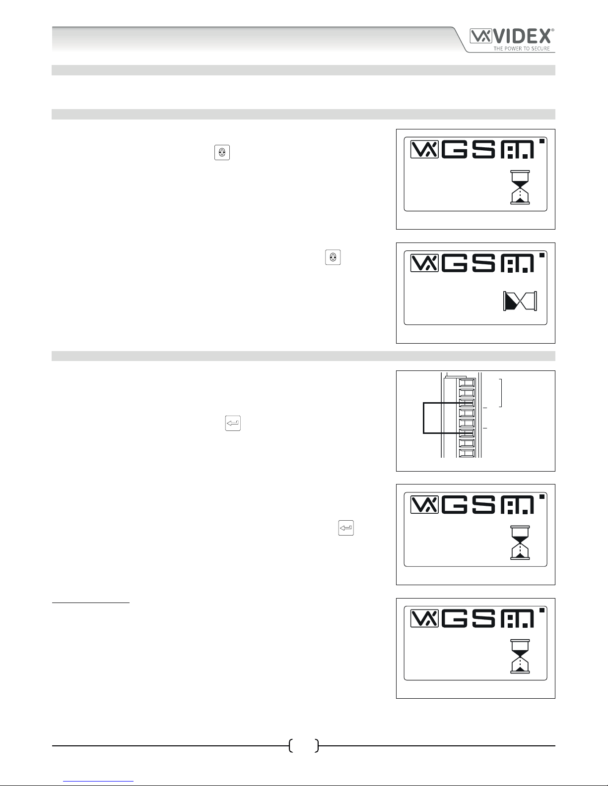
RESETTING THE MASTER CODE TO 1111 4x1
1. Ensure the power is switched o to the digital GSM panel.
2. Press and hold down the ‘0’ button, , and keep it pressed down while the
power is switched back on.
3. The graphical display and the keypad buttons will illuminate.
4. After a brief delay the display will show the Videx GSM logo and current rmware
version number, as shown in Fig.29.
5. After another delay the GSM will emit a beep and below the Videx logo it will
indicate the digital GSM is registering with the network, as shown in Fig.30.
6. When the display shows that it is registering release the ‘0’ button,
.
7. After a further delay the display will then show the default welcome screen (refer
to Fig.100 for the Art.4812 and Fig.101 for the Art.4812R on page 61).
8. The master code has been reset back to factory default 1111 (4x1).
Fig. 29
Fig. 30
FULL SYSTEM RESET
1. Ensure the power is switched o to the digital GSM panel.
2. On the rear of the GSM panel link out the GND and PTE terminals, as shown in
Fig.31.
3. Press and hold down the ‘ENTER’ button,
, and keep it pressed down while the
power is switched back on.
4. The graphical display and the keypad buttons will illuminate.
5. After a brief delay the display will show the Videx GSM logo and current rmware
version number, as shown in Fig.32.
6. After another delay the GSM will emit a beep and below the Videx logo it will
indicate the digital GSM is resetting, as shown in Fig.33.
7. When the display shows that it is resetting release the ‘ENTER’ button,
.
8. After a further delay the digital GSM will automatically follow the ‘power up
initialisation sequence’ as described on page 20.
9. The digital GSM panel has been fully reset.
IMPORTANT NOTE: When performing a full system reset all the data stored in
the digital GSM will be deleted from the panel. If any data is still required it is
recommended that this information is rst downloaded from the digital GSM using
the GSMSK PC software and then saved. It can then later be uploaded back into the
digital GSM after the full reset has been completed.
Fig. 31
Fig. 32
Fig. 33
PLEASE WAIT...
VER DG4.0.0
VIDEX
PLEASE WAIT...
REGISTERING...
VIDEX
A
B
GND
12V
0V
PTE
AI
TRD
RS485
PLEASE WAIT...
VER DG4.0.0
VIDEX
PLEASE WAIT...
VIDEX
RESETTING...
Page 22
66251750-EN - V1.0 - 05/06/17
22
4000 Series Vandal Resistant Digital GSM - Technical Manual
4000 Series Vandal Resistant Digital GSM Audio Intercom with Proximity
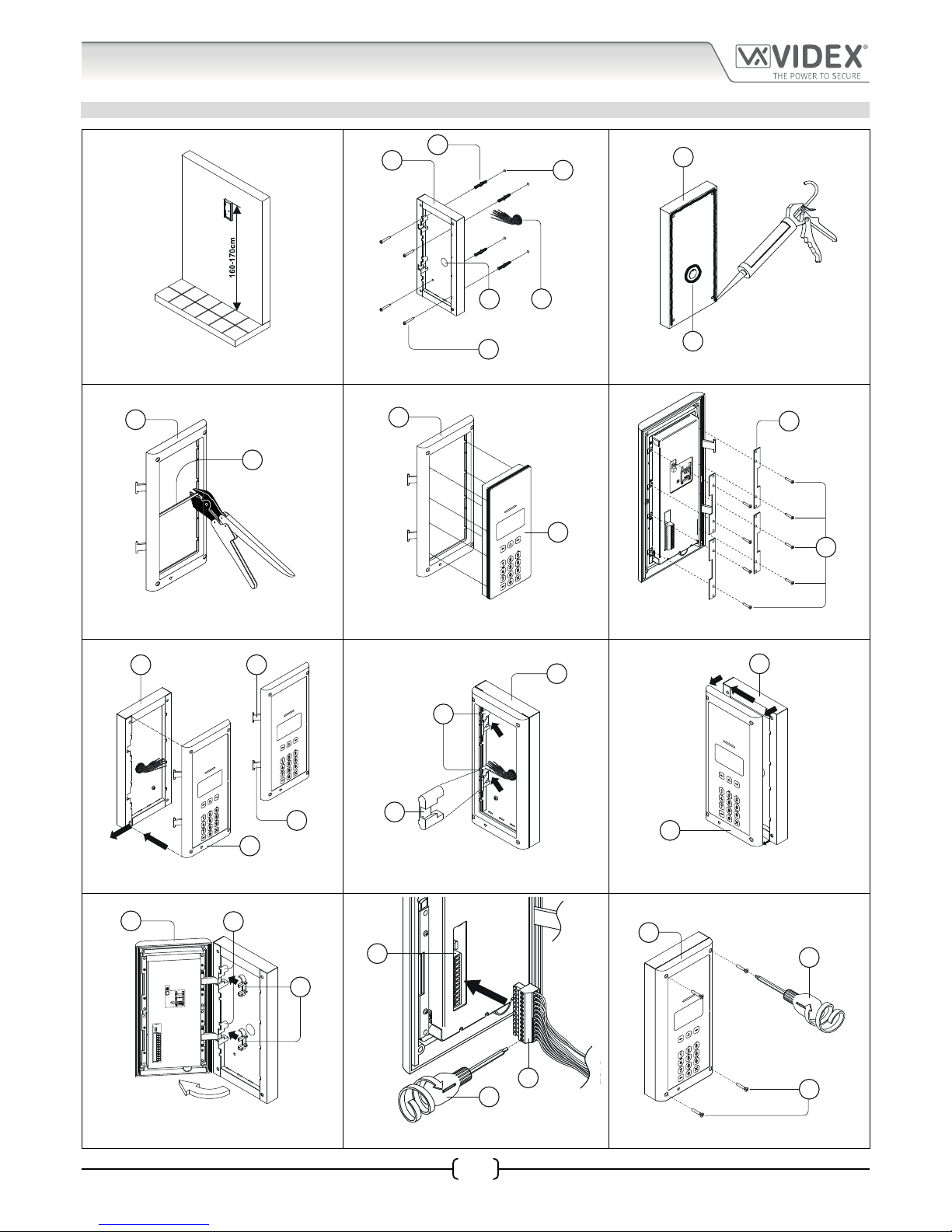
4000 Series Back Box Installation
EXAMPLE: INSTALLING A 4000 SERIES TWO MODULE SURFACE BACK BOX ART. 4882
Fig. 34 Fig. 35 Fig. 36
Fig. 37 Fig. 38 Fig. 39
Fig. 40 Fig. 41 Fig. 42
Fig. 43 Fig. 44 Fig. 45
C
F
E
D
B
A
C
D
G
H
H
I
12
ON
J
K
C
L
H
L
M
C
M
C
H
N
M
H
%0
O
P
Q
P
R
H
Page 23

66251750-EN - V1.0 - 05/06/17
23
4000 Series Vandal Resistant Digital GSM - Technical Manual
4000 Series Vandal Resistant Digital GSM Audio Intercom with Proximity
4000 Series Back Box Installation
INSTALLING A SURFACE MOUNT DOOR STATION
1. Place the surface box against the wall (165-170cm between the top of the box and the oor level as shown in Fig.34) and mark
the xing holes A for the wall plugs B and the hole for the cables E (Fig.35). Observe the orientation of the box with the hinge
on the left;
In order to prevent water ingress we highly recommend using a silicon sealant between the wall and the back box C
(Fig.36) and around the back box opening D (Fig.36);
2. As shown in Fig.35, drill the xing holes A, insert the wall plugs B and feed the cables E through the surface box opening D, x
the surface box C to the wall using the screws F;
3. Remove the cross bar G from the module support frame H using the approprite hand tool (where required it may be necessary
to wear the appropriate clothing, e.g. protective gloves and eye protection, when doing this) as shown in Fig.37;
4. Before installation of the module support frame H to the surface box G, t the module I to the support frame H as shown in
Fig.38 then, as shown in Fig.39, t the module xing brackets J using the xing screws K;
5. Next take the frame’s hinges L and hook the module support frame H to the surface box C, starting from the left following the guide
arrows, as shown in Fig.40. Ensure that the frame’s hinges L (Fig.40) t inside the relevant hinge mounts M inside the surface box C,
following the guide arrows, as shown in Fig.41;
6. Pull back the module support frame H from the surface box C while moving it slightly to the left, following the guide arrows,
as shown in Fig.42;
7. Next open the module support frame H and clip the hinge locks N to the hinge mounts M, following the guide arrows, as shown
in Fig.43;
8. Make the required wiring connections into the terminal block O using the screwdriver provided P (using the at blade end)
then plug the terminal block O into the module’s terminal block connector Q, as shown in Fig.44. Make any other necessary
panel adjustments required (connecting the antenna cable, tting the SIM card and setting the dip-switches etc.);
9. After the system has been tested and is working correctly, move back the module support frame H carefully and then x it to the
surface box C using the screwdriver provided P (using the torx end) and the torx pin security screws provided R
, as shown in Fig.45.
Note: do not over tighten the screws more than is necessary.
Note: if additional holes are made in the surface box, oxidation problems may appear unless the unprotected metal is
coated with a protective paint.
Page 24

66251750-EN - V1.0 - 05/06/17
24
4000 Series Vandal Resistant Digital GSM - Technical Manual
4000 Series Vandal Resistant Digital GSM Audio Intercom with Proximity
EXAMPLE: INSTALLING A 4000 SERIES TWO MODULE FLUSH BACK BOX ART. 4852
Fig. 46 Fig. 47 Fig. 48
Fig. 49 Fig. 50 Fig. 51
Fig. 52 Fig. 53 Fig. 54
Fig. 55 Fig. 56
E
w
h
d
C
D
C
E
P
O
E
C
L
H
L
M
C
C
H
N
M
H
O
Q
P
R
H
4000 Series Back Box Installation
Page 25

66251750-EN - V1.0 - 05/06/17
25
4000 Series Vandal Resistant Digital GSM - Technical Manual
4000 Series Vandal Resistant Digital GSM Audio Intercom with Proximity
INSTALLING A FLUSH MOUNTING DOOR STATION
1. It is recommended that the ush box C is mounted into the wall approximately 165-170cm between the top of the box and the
oor level as shown in Fig.46.
2. Using the ush box C and the hole dimensions (w=120mm x h=263.2mm x d=46mm), as shown in Fig.47, use appropriate
tools to cut out the recommended hole size in the wall (where required it may be necessary to wear the appropriate clothing,
e.g. protective gloves and eye protection, when doing this). Remember to allow room for the connecting cables E (Fig.47);
Before tting the ush box C into the wall it is recommended that in order to prevent water ingress a silicon sealant is
used between the wall and the ush box C (Fig.48) and around the ush box openings D (Fig.48);
3. Set the ush box C into the hole in the wall feeding the connecting cables E through the appropriate ush box opening D, as
shown in Fig.49;
4. Follow steps 3 and 4, from ‘installing a surface mounting door station’ , to t the module into the module support frame H as
shown in Fig.37, Fig.38 and Fig.39 (on pages 22 and 23);
5. Next take connecting cables E and make the required terminal connections into the terminal block O using the screwdriver
provided P (using the at blade end), as shown in Fig.50;
6. Take the frame’s hinges L and hook the module support frame H to the ush box C, starting from the left following the guide arrows,
as shown in Fig.51. Ensure that the frame’s hinges L (Fig.51) t inside the relevant hinge mounts M inside the ush box C, as shown
in Fig.52;
7. Next close in the front support frame H and then pull it back from the ush box C while moving it slightly to the left, following
the guide arrows, as shown in Fig.53;
8. With the front support frame H opened out (to allow for easy access to the hinge mounts M) take the hinge locks N and clip them in
place locking into the hinge mounts M, following the guide arrows as shown in Fig.54;
9. Next open the module support frame H and clip the hinge locks N to the hinge mounts M, following the guide arrows, as shown
in Fig.54;
10. Plug the terminal block O (from step 5, Fig.50) into the module’s terminal block connector Q, as shown in Fig.55. Make any
other necessary panel adjustments required (connecting the antenna cable, tting the SIM card and setting the dip-switches
etc.);
11. After the system has been tested and is working correctly, move back the module support frame H carefully and then x it to the ush
box C using the screwdriver provided P (using the torx end) and the torx pin security screws provided R, as shown in Fig.56.
Note: do
not over tighten the screws more than is necessary.
NOTES
• The screwdriver’s blade has two sides, one at and one torx, to select one of them unplug the blade from the screwdriver body
and plug it into the required side.
4000 Series Back Box Installation
Page 26

66251750-EN - V1.0 - 05/06/17
26
4000 Series Vandal Resistant Digital GSM - Technical Manual
4000 Series Vandal Resistant Digital GSM Audio Intercom with Proximity
Programming via Alpha-Numeric Keypad
THE ALPHANUMERIC KEYPAD
Programming can be carried out using the onboard alpha-numeric keypad. When in programming mode the keypad can be used
similar to mobile phone text typing. The following alpha-numeric table can be used when entering a username for example. The
table shows the characters and symbols that can be entered into the panel by pressing a specic numeric button one or more times
to select the character or symbol desired.
For the Art.4812R with the scroll buttons,
and are not used. The call button can also be used to conrm entry.
For the Art.4812 the alpha buttons A-F are not used.
Number of Presses
Button No.
123456789
1 <space> . & 1
2ABC2abc
3DEF3def
4GHI4ghi
5JKL5jkl
6MNO6mno
7PQRS7pqrs
8TUV8tuv
9WXYZ9wxyz
0
+-*/0
unused buttons
conrm entry
delete previous character/symbol and cancel
Example:
When entering an apartment name, to type the name “VIDEX” the following buttons can be pressed on the keypad:
Press button “8” , , 3 times = “V”;
Press button “4” , , 3 times = “I”;
Press button “3” , , once = “D”;
Press button “3” , , twice = “E”;
Press button “9” , , twice = “X”;
Page 27
66251750-EN - V1.0 - 05/06/17
27
4000 Series Vandal Resistant Digital GSM - Technical Manual
4000 Series Vandal Resistant Digital GSM Audio Intercom with Proximity
Programming Flowcharts
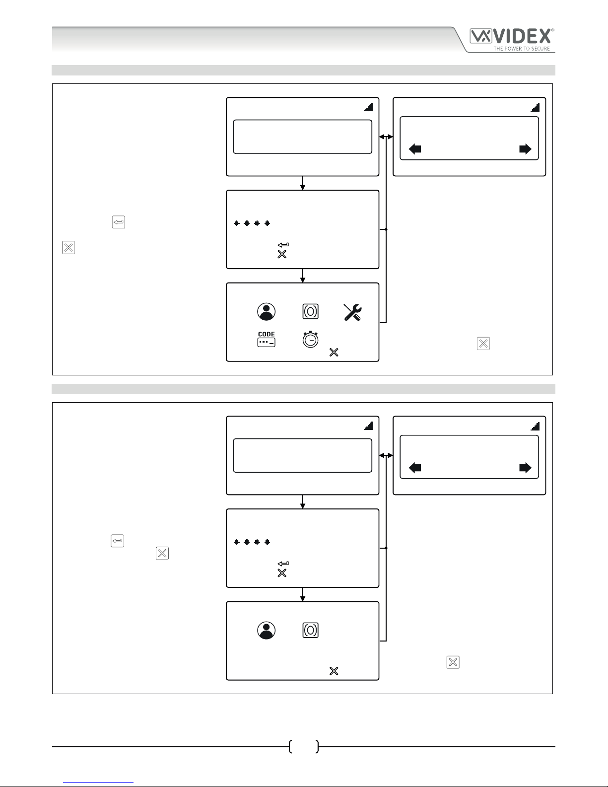
ACCESSING MAIN PROGRAMMING MENU
4812 4812R
DEFAULT WELCOME SCREEN
18/11/16 08:35
Enter Number
18/11/16 08:35
Or Search
Enter Number
ENTER MASTER CODE
First press ‘0’. Enter the 4 digit master code
(the default master code is ‘1111’), press the
ENTER button
to continue to the main
programming menu or the CLEAR button
to return to the default welcome screen.
ENTER A CODE
to confirm
to cancel
MAIN PROGRAMMING MENU
From the main programming menu the
following can be accessed:
1.Apartment menu, 2.Proximity menu,
3.General settings, 4.Access code settings,
5.Time settings. Press the relevant number
to continue onto the next menu.
PROG. MENU
VER DG4.0.1
1:
2:
3:
4:
5:
to exit
To exit from the main programming menu
press the CLEAR button
to return to the
default welcome screen.
ACCESSING ADMIN MENU
4812 4812R
DEFAULT WELCOME SCREEN
18/11/16 08:35
Enter Number
18/11/16 08:35
Or Search
Enter Number
ENTER ADMIN CODE
First press ‘0’. Enter the 4 digit admin code
(the default admin code is ‘0000’), press the
ENTER button
to continue to the admin
menu or the CLEAR button
to return to
the default welcome screen.
ENTER A CODE
to confirm
to cancel
ADMIN MENU
From the admin menu the following can be
accessed:
1.Apartment menu, 2.Proximity menu.
Press the relevant number to continue onto
the next menu.
PROG. MENU
1:
2:
to exit
VER DG4.0.1
To exit from the admin menu press the
CLEAR button
to return to the default
welcome screen.
Page 28

66251750-EN - V1.0 - 05/06/17
28
4000 Series Vandal Resistant Digital GSM - Technical Manual
4000 Series Vandal Resistant Digital GSM Audio Intercom with Proximity
Programming Flowcharts
1. APARTMENT MENU
MAIN PROGRAMMING MENU
PROG. MENU
VER DG4.0.1
1:
2:
3:
4:
5:
to exit
To exit from the main programming menu
press the CLEAR button
to return to the
default welcome screen.
APARTMENT MENU
Press ‘1’ to add/modify the apartment details
and continue onto the mem.location screen
or press ‘2’ to delete the apartment details
and continue onto the mem. location screen.
To return to the main programming menu
press the CLEAR button
.
to exit
1 . ADD/MODIFY APT
2 . DELETE APT
MEMORY LOCATION SCREEN
to confirm
to cancel
MEMORY LOCATION
to confirm
to cancel
MEMORY LOCATION
MEMORY LOCATION
Enter the mem. location to add/modify the
apartment details then press the ENTER
button
to conrm. To exit the mem.
location and return to the apartment menu
press the CLEAR button
.
to confirm
to cancel
MEMORY LOCATION
101
to confirm
to cancel
MEMORY LOCATION
101
APARTMENT INFO SCREEN
In the mem. location it is possible to add/
modify the following apartment details:
1.Apartment number, 2.Door code, 3.DTO
number, 4.Timeband, 5.User Name, 6.TEL1,
7.TEL2, 8.TEL3, 9.TEL4. Press the relevant
number to continue onto the appropriate
editing screen.
to exit
SELECT 1-9
1.APT:
3.DTO:
5.NAME:
6.TEL 1:
7.TEL 2:
8.TEL 3:
9.TEL 4:
2.CODE:
4.TB:
DELETED
to confirm
to cancel
APT:
to confirm
to cancel
CODE:
to confirm
to cancel
DTO:
(1=SET, 0=UNSET)
1. APARTMENT NUMBER 2. DOOR CODE 3. DTO DIAL TO OPEN
Enter an apartment number then press the
ENTER button
to conrm. To cancel out
of the selection and return to the apartment
information screen press the CLEAR button
.
Enter a door access code then press the
ENTER button
to conrm. To cancel out
of the selection and return to the apartment
information screen press the CLEAR button
.
Press ‘1’ to set or press ‘2’ to unset the DTO
facility, then press the ENTER button
to
conrm. To cancel out of the selection and
return to the apartment information screen
press the CLEAR button
.
Page 29

66251750-EN - V1.0 - 05/06/17
29
4000 Series Vandal Resistant Digital GSM - Technical Manual
4000 Series Vandal Resistant Digital GSM Audio Intercom with Proximity
Programming Flowcharts
1. APARTMENT MENU CONTINUED
to exit
1 . ADD/MODIFY APT
2 . DELETE APT
to exit
SELECT 1-9
1.APT:
3.DTO:
5.NAME:
6.TEL 1:
7.TEL 2:
8.TEL 3:
9.TEL 4:
2.CODE:
4.TB:
If no details require modifying to return back
to the apartment menu press the CLEAR
button
.
to confirm
to cancel
TB:
0
to confirm
to cancel
NAME:
_
to confirm
to cancel
TEL 1:
4. TIMEBANDS 5. USER NAME 6. TEL1 PRIMARY
Enter a timeband (0 - 9), then press the
ENTER button
to conrm. To cancel out
of the selection and return to the apartment
information screen press the CLEAR button
.
Use the alpha-numeric keypad (refer to the alpha-
numeric table on page 13) to enter the user name
(16 characters max.), then press the ENTER button
to confirm. To delete a character or cancel out
of the selection and return to the previous screen
press the CLEAR button
.
Enter the primary telephone number, then press
the ENTER button
to confirm. To delete
a character or cancel out of the selection and
return to the apartment information screen
press the CLEAR button
.
to exit
1 . ADD/MODIFY APT
2 . DELETE APT
to exit
SELECT 1-9
1.APT:
3.DTO:
5.NAME:
6.TEL 1:
7.TEL 2:
8.TEL 3:
9.TEL 4:
2.CODE:
4.TB:
If no details require modifying to return back
to the apartment menu press the CLEAR
button
.
to confirm
to cancel
TEL 2:
to confirm
to cancel
TEL 3:
to confirm
to cancel
TEL 4:
7. TEL2 DIVERT 1 8. TEL3 DIVERT 2 9. TEL4 DIVERT 3
Enter the 1st divert telephone number, then
press the ENTER button
to confirm. To
delete a character or cancel out of the selection
and return to the apartment information screen
press the CLEAR button
.
Enter the 2nd divert telephone number, then
press the ENTER button
to confirm. To
delete a character or cancel out of the selection
and return to the apartment information screen
press the CLEAR button
.
Enter the 3rd divert telephone number, then
press the ENTER button
to confirm. To
delete a character or cancel out of the selection
and return to the apartment information screen
press the CLEAR button
.
Page 30

66251750-EN - V1.0 - 05/06/17
30
4000 Series Vandal Resistant Digital GSM - Technical Manual
4000 Series Vandal Resistant Digital GSM Audio Intercom with Proximity
2. PROXIMITY MENU
MAIN PROGRAMMING MENU
PROG. MENU
VER DG4.0.1
1:
2:
3:
4:
5:
to exit
To exit from the main programming menu
press the CLEAR button
to return to the
default welcome screen.
PROXIMITY MENU
Press ‘1’ to add a proximity fob and continue
onto the mem. location screen or press ‘2’ to
delete a proximity fob and continue onto the
mem. location screen. To return to the main
programming menu press the CLEAR button
.
to exit
1 . ADD/MODIFY FOB
2 . DELETE FOB
MEMORY LOCATION SCREEN
to confirm
to cancel
MEMORY LOCATION
to confirm
to cancel
MEMORY LOCATION
MEMORY LOCATION
Enter the mem. location to add the proximity
fob to and then press the ENTER button
to conrm. To exit the mem. location and
return to the proximity menu press the CLEAR
button
.
to confirm
to cancel
MEMORY LOCATION
101
to confirm
to cancel
MEMORY LOCATION
101
PRESENT FOB SCREEN
(please note that the example shown is based
on the prox bytes being set to read for 2 bytes)
to confirm
to cancel
PRESENT FOB
65535
DELETED
PRESENT FOB
On the present fob screen place the fob
towards the top of the display (near the panel’s
speaker grill). The fob’s 5 digit site code will be
displayed in the middle of the screen. Press the
ENTER button
to conrm and return back
to the proximity menu.
to confirm
to cancel
PRESENT FOB
16513
To exit from the present fob screen without
saving any fob data press the CLEAR button
to return back to the proximity menu.
Programming Flowcharts
Page 31
66251750-EN - V1.0 - 05/06/17
31
4000 Series Vandal Resistant Digital GSM - Technical Manual
4000 Series Vandal Resistant Digital GSM Audio Intercom with Proximity
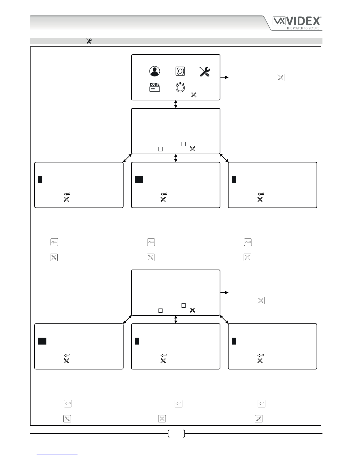
3. GENERAL SETTINGS
MAIN PROGRAMMING MENU
PROG. MENU
VER DG4.0.1
1:
2:
3:
4:
5:
to exit
To exit from the main programming menu
press the CLEAR button
to return to the
default welcome screen.
GENERAL SETTINGS MENU
On the settings screen it is possible to adjust/
set the following: 1.Aux mode, 2.Speaker
volume, 3.Mic volume, 4.Speech board
volume, 5.Speech board mode, 6.Prox bytes,
7.Prox enable/disable, 8.Gate mode. Press the
relevant button to change the settings.
1. AUX MODE:1
2. SPK VOL:10
3. MIC VOL:5
4. SB VOL:85
5. SB MODE:3
6. PROX BYTES:2
7. PROX ENABLED:
8. GATE:
to exit
to confirm
to cancel
AUX MODE:
(0-2)
1
to confirm
to cancel
SPK VOL:
(0-14)
10
to confirm
to cancel
MIC VOL:
(0-7)
5
1. AUXILIARY MODE 2. SPEAKER VOLUME 3. MIC VOLUME
The default aux mode will be displayed on
the screen. To change the mode enter the aux
mode required (0 - 2), then press the ENTER
button
to conrm. To cancel and return
to the general settings menu press the CLEAR
button
.
The default speaker volume will be displayed
on the screen. To adjust the volume enter the
level required (0 - 14), then press the ENTER
button
to conrm. To cancel and return
to the general settings menu press the CLEAR
button
.
The default mic volume will be displayed on
the screen. To adjust the volume enter the
level required (0 - 7), then press the ENTER
button
to conrm. To cancel and return
to the general settings menu press the CLEAR
button
.
GENERAL SETTINGS MENU
1. AUX MODE:1
2. SPK VOL:10
3. MIC VOL:5
4. SB VOL:85
5. SB MODE:3
6. PROX BYTES:2
7. PROX ENABLED:
8. GATE:
to exit
If no settings require adjusting then to return
to the main programming menu press the
CLEAR button
.
to confirm
to cancel
SB VOL:
(0-99)
85
to confirm
to cancel
SB MODE:
(1-3)
3
to confirm
to cancel
PROX BYTES:
(2-4)
2
4. SPEECH BOARD VOLUME 5. SPEECH BOARD MODE 6. PROXIMITY BYTES
The default speech board volume will be
displayed on the screen. To adjust the volume
enter the level required (0 - 99), then press the
ENTER button
to conrm. To cancel and
return to the general settings menu press the
CLEAR button
.
The default speech board mode will be displayed
on the screen and is set to mode 3 (combined
speech playback). Select the required mode then
press the ENTER button
to confirm. To cancel
and return to the general settings menu press the
CLEAR button
.
The default prox byte setting will be displayed
on the screen and is set to read for 2 bytes. Select
the prox byte setting required then press the
ENTER button
to confirm. To cancel and
return to the general settings menu press the
CLEAR button
.
Programming Flowcharts
Page 32

66251750-EN - V1.0 - 05/06/17
32
4000 Series Vandal Resistant Digital GSM - Technical Manual
4000 Series Vandal Resistant Digital GSM Audio Intercom with Proximity
3. GENERAL SETTINGS CONTINUED
GENERAL SETTINGS MENU
1. AUX MODE:1
2. SPK VOL:10
3. MIC VOL:5
4. SB VOL:85
5. SB MODE:3
6. PROX BYTES:2
7. PROX ENABLED:
8. GATE:
to exit
If no settings require adjusting then to return
to the main programming menu press the
CLEAR button
.
to confirm
to cancel
PROX ENABLE:
(0-1)
GATE:
(0-1)
3
to confirm
to cancel
7. PROXIMITY READER ENABLE 8. GATE MODE
By default the onboard proximity reader is
disabled (switched OFF), the check box will be
‘unchecked’. To enable the reader press 1 then
the ENTER button
to confirm. To cancel and
return to the general settings menu press the
CLEAR button
.
By default the panel’s gate mode is enabled, the
check box will be ‘ticked’. To change this setting
so that the panel displays/announces the ‘door
is open’ press 0 then the ENTER button
to confirm. To cancel and return to the general
settings menu press the CLEAR button
.
Programming Flowcharts
Page 33

66251750-EN - V1.0 - 05/06/17
33
4000 Series Vandal Resistant Digital GSM - Technical Manual
4000 Series Vandal Resistant Digital GSM Audio Intercom with Proximity
4. CODE MENU
MAIN PROGRAMMING MENU
PROG. MENU
VER DG4.0.1
1:
2:
3:
4:
5:
to exit
To exit from the main programming menu
press the CLEAR button
to return to the
default welcome screen.
CODE MENU
On the main code menu it is possible to
change the following codes: 1.Master code,
2.Admin code, 3.Trade code. Press the
relevant button to change the code. To return
to the main programming menu press the
CLEAR button
.
to exit
1 . MASTER CODE
2 . ADMIN CODE
3 . TRADE CODE
to confirm
to cancel
MASTER CODE
(4 DIGITS)
1111
to confirm
to cancel
ADMIN CODE
(4 DIGITS)
0000
to confirm
to cancel
TRADE CODE
(4 DIGITS)
2222
1. MASTER CODE 2. ADMIN CODE 3. TRADE CODE
The default or master code (1111) will be
displayed on the screen. To change the code
enter the new code required then press the
ENTER button
to conrm. To cancel
and return to the main code menu press the
CLEAR button
.
The default admin code (0000) will be
displayed on the screen. To change the code
enter the new code required then press the
ENTER button
to conrm. To cancel
and return to the main code menu press the
CLEAR button
.
The default or current trade code (2222) will
be displayed on the screen. To change the
code enter the new code required then press
the ENTER button
to conrm. To cancel
and return to the main code menu press the
CLEAR button
.
Programming Flowcharts
Page 34
66251750-EN - V1.0 - 05/06/17
34
4000 Series Vandal Resistant Digital GSM - Technical Manual
4000 Series Vandal Resistant Digital GSM Audio Intercom with Proximity
Programming Flowcharts
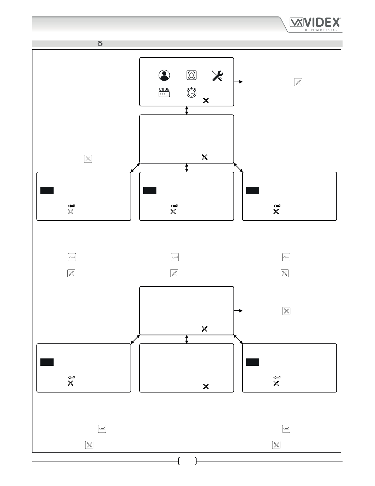
5. TIME SETTINGS MENU
MAIN PROGRAMMING MENU
PROG. MENU
VER DG4.0.1
1:
2:
3:
4:
5:
to exit
To exit from the main programming menu
press the CLEAR button
to return to the
default welcome screen.
TIME SETTINGS MENU
On the time settings menu it is possible to setup
the following: 1.Call time, 2.Divert time, 3.Open
time, 4.Aux time, 5.Timebands, 6.LCD time. Press
the relevant button to setup the appropriate
time. To return to the main programming menu
press the CLEAR button
.
to exit
1 . CALL TIME:040
2 . DIVERT TIME:015
3 . OPEN TIME:005
4 . AUX TIME:005
5 . TIMEBANDS
6 . LCD TIME:000
to confirm
to cancel
CALL TIME:
(1-255 Sec)
040
to confirm
to cancel
DIVERT TIME:
(1-255 Sec)
015
to confirm
to cancel
OPEN TIME:
(1-255 Sec)
005
1. CALL TIME 2. DIVERT TIME 3. OPEN TIME
The default call time will be displayed on the
screen. To change the time enter the new
time required (1-255 seconds) then press the
ENTER button
to conrm. To cancel and
return to the time settings menu press the
CLEAR button
.
The default divert time will be displayed on
the screen. To change the time enter the new
time required (1-255 seconds) then press the
ENTER button
to conrm. To cancel and
return to the time settings menu press the
CLEAR button
.
The default door open time will be displayed
on the screen. To change the time enter the
new time required (1-255 seconds) then press
the ENTER button
to conrm. To cancel
and return to the time settings menu press
the CLEAR button
.
TIME SETTINGS MENU
to exit
1 . CALL TIME:040
2 . DIVERT TIME:015
3 . OPEN TIME:005
4 . AUX TIME:005
5 . TIMEBANDS
6 . LCD TIME:000
To exit from the time settings menu press
the CLEAR button
to return to the main
programming menu.
to confirm
to cancel
AUX TIME:
(1-255 Sec)
005
TIMEBANDS
0> 0000-2359 1> 0000-2359
2> 0000-2359 3> 0000-2359
4> 0000-2359 5> 0000-2359
6> 0000-2359 7> 0000-2359
8> 0000-2359 9> 0000-2359
to exit
SELECT 1-9
to confirm
to cancel
LCD TIME:
(1-255 Sec)
000
4. AUX TIME 5. TIMEBANDS 6. LCD TIME
The default auxiliary input time will be
displayed on the screen. To change the time
enter the new time required (1-255 seconds)
then press the ENTER button
to conrm.
To cancel and return to the time settings menu
press the CLEAR button
.
Refer to the owchart on page 31 to set up
timebands 1-9. Timeband 0 is the default
timeband and is set as “0000-2359” and
cannot be changed.
The default LCD switch time will be displayed
on the screen. To change the time enter the
new time required (1-255 seconds) then press
the ENTER button
to conrm. To cancel
and return to the time settings menu press the
CLEAR button
.
Page 35

66251750-EN - V1.0 - 05/06/17
35
4000 Series Vandal Resistant Digital GSM - Technical Manual
4000 Series Vandal Resistant Digital GSM Audio Intercom with Proximity
Programming Flowcharts
5. TIME SETTINGS MENU CONTINUED
TIME SETTINGS MENU
to exit
1 . CALL TIME:040
2 . DIVERT TIME:015
3 . OPEN TIME:005
4 . AUX TIME:005
5 . TIMEBANDS
6 . LCD TIME:000
If no time settings require adjusting then to
return to the main programming menu press
the CLEAR button
.
TIMEBAND LIST
From the timeband list it is possible to
select a timeband that requires changing
or setting up. Press the relevant button,
from 1-9, to change the timeband required.
If no timeband requires amending to
return to the time settings menu press the
CLEAR button
.
TIMEBANDS
0> 0000-2359 1> 0000-2359
2> 0000-2359 3> 0000-2359
4> 0000-2359 5> 0000-2359
6> 0000-2359 7> 0000-2359
8> 0000-2359 9> 0000-2359
to exit
SELECT 1-9
TIMEBAND SCREEN
*When entering a time period on the
timebands screen the time must be entered
using 24 hour clock notation, e.g. a timeband
of 9:30am to 4:35pm would be entered as
09:30-16:35.
to confirm
to cancel
TIMEBANDS
1>00:00-23:59
The current time period will be displayed on the
screen. To change the timeband use the alpha-
numeric keypad to enter the new timeband*
required then press the ENTER button
to
conrm. To cancel and return to the timeband
list press the CLEAR button
.
Page 36

66251750-EN - V1.0 - 05/06/17
36
4000 Series Vandal Resistant Digital GSM - Technical Manual
4000 Series Vandal Resistant Digital GSM Audio Intercom with Proximity
Programming Screens
MAIN PROGRAMMING MENU
From the main programming menu (refer to Fig.57) it is possible to access the
following sub menus:
1. Apartment menu
2. Proximity menu
3. General settings menu
4. Code menu
5. Time settings menu
Fig. 57
ADMIN MENU
From the admin menu (refer to Fig.58) it is possible to only access the following two
sub menus:
1. Apartment menu
2. Proximity menu
Fig. 58
Please note that the current rmware version of the digital GSM is shown in the top right corner of both the main programming
and admin menus.
1.1 APARTMENT MENU ADD/MODIFY APT
From the apartment menu (refer to Fig.59) it is possible to edit the following details:
1. Add or modify apartment details
2. Delete apartment details
Selecting option 1 from the apartment menu will rst access the memory location
screen and then from there the apartment information screen (refer to Fig.60).
The apartment information screen has 9 available options that allows the following
information to be entered, enabled and/or assigned:
1. Apartment number (APT)
2. Door/gate access code (CODE)
3. Dial to open number enable (DTO)
4. Timeband assignment (TB)
5. Username (NAME)
6. Primary telephone number (TEL1)
7. First divert number (TEL2)
8. Second divert number (TEL3)
9. Third divert (TEL4)
Fig. 59
Fig. 60
1.1.1 APARTMENT NUMBER APT
The apartment number can be entered on the apartment screen (refer to Fig.61) and
can be made up of a maximum of 6 digits or letters (A - F only) or a combination of
both e.g. apartment 100A, 100B etc.
Fig. 61
PROG. MENU VER DG4.0.1
1:
2: 3:
4:
5:
to exit
PROG. MENU
1:
2:
to exit
VER DG4.0.1
to exit
1 . ADD/MODIFY APT
2 . DELETE APT
to exit SELECT 1-9
1.APT:
3.DTO:
5.NAME:
6.TEL 1:
7.TEL 2:
8.TEL 3:
9.TEL 4:
2.CODE:
4.TB:
to confirm
to cancel
APT:
Page 37

66251750-EN - V1.0 - 05/06/17
37
4000 Series Vandal Resistant Digital GSM - Technical Manual
4000 Series Vandal Resistant Digital GSM Audio Intercom with Proximity
1.1.2 DOOR/GATE ACCESS CODE
The door/gate access code can be entered on the code screen (refer to Fig.62) and
can be made up of a maximum of 6 digits (no letters).
Fig. 62
1.1.3 DIAL TO OPEN NUMBER DTO
The dial to open (DTO) number can be
enabled on the DTO screen. Enter “1” to
enable (set, refer to Fig.63) the dial to
open number or “0” to disable (unset,
refer to Fig.64) the dial to open number.
When set the primary and 3 divert
numbers are automatically set as dial to
open numbers.
Fig. 63 Fig. 64
1.1.4 TIMEBAND TB
A timeband can be assigned, to an apartment or apartments for when they can be
called, on the timeband assignment screen (refer to Fig.65). The default timeband
setting is “0” (0000 - 2359), calls to the apartments are enabled all the time. Timeband
“0” cannot be changed, timebands 1 - 9 are programmable and can be set on the
timeband set up screen (refer to Fig.96 and Fig.97 on page 43).
Fig. 65
1.1.4 USERNAME NAME
A username can be entered for an apartment on the username screen (refer to Fig.66).
A maximum of 16 characters can be entered via the alpha-numeric keypad following
the keypad programming table on page 26.
Fig. 66
1.1.5 TELEPHONE NUMBERS PRIMARY NUMBER AND 3 DIVERT NUMBERS
Options 6 (TEL1), 7 ( TEL2), 8 (TEL3) and 9 (TEL4) on the apartment information screen is
where the primary telephone number and the 3 divert numbers can be programmed
respectively (refer to Fig.67, Fig.68, Fig.69 and Fig.70) and can be a maximum of 30
digits. If a landline number is being programmed then the full regional dialing code
must be included as part of the telephone number.
Fig. 67
to confirm
to cancel
CODE:
to confirm
to cancel
DTO:
(1=SET, 0=UNSET)
3
to confirm
to cancel
DTO:
(1=SET, 0=UNSET)
to confirm
to cancel
TB:
0
to confirm
to cancel
NAME:
_
to confirm
to cancel
TEL 1:
Programming Screens
Page 38

66251750-EN - V1.0 - 05/06/17
38
4000 Series Vandal Resistant Digital GSM - Technical Manual
4000 Series Vandal Resistant Digital GSM Audio Intercom with Proximity
Fig. 68 Fig. 69 Fig. 70
1.2 APARTMENT MENU DELETE APT
Selecting option 2 from the apartment
menu will access the memory location
screen (refer to Fig.71). Enter the
memory location of the apartment to
delete and press the ENTER button.
The deleted screen will appear (refer to
Fig.72) to conrm the apartment details
have been deleted and then return back
to the apartment menu.
Fig. 71 Fig. 72
IMPORTANT NOTE: When deleting a memory location all the user’s information is deleted from the digital GSM intercom
(telephone numbers, username, apartment number etc.).
2.1 PROXIMITY MENU ADD/MODIFY FOB
From the proximity menu (refer to Fig.73) it is possible to edit the following details:
1. Add or modify fob details
2. Delete fob details
Selecting option 1 from the proximity menu will rst access the memory location
screen (refer to Fig.71) and then from there the default present fob screen. The default
present fob screen that the panel shows will depend on which prox byte setting the
panel has been set to (refer to Fig.74 for 2 bytes, Fig.75 for 3 bytes and Fig.76 for 4
bytes). The prox byte setting can be changed on the general settings screen, option 6.
Also see prox byte notes on page 40.
Fig. 73
Fig. 74 Fig. 75 Fig. 76
When the present fob screen appears place the proximity fob towards the display, in
front of the fob symbol, as shown in Fig.77. The display will show the fob number just
below the fob symbol once it has read the fob. To conrm and save the details press
the ENTER button and the screen will revert back to the proximity menu (see Fig.73).
Fig. 77
2.2 PROXIMITY MENU DELETE/FOB
Selecting option 2 from the proximity menu will access the memory location screen (refer to Fig.71). Enter the memory location of
the fob to delete and press the ENTER button. The deleted screen will appear (refer to Fig.72) to conrm the apartment details have
been deleted and then revert back to the proximity menu.
to confirm
to cancel
TEL 2:
to confirm
to cancel
TEL 3:
to confirm
to cancel
TEL 4:
to confirm
to cancel
MEMORY LOCATION
DELETED
to exit
1 . ADD/MODIFY FOB
2 . DELETE FOB
to confirm
to cancel
PRESENT FOB
65535
to confirm
to cancel
PRESENT FOB
00255 65535
to confirm
to cancel
PRESENT FOB
65535 65535
to confirm
to cancel
PRESENT FOB
18915
Programming Screens
Page 39

66251750-EN - V1.0 - 05/06/17
39
4000 Series Vandal Resistant Digital GSM - Technical Manual
4000 Series Vandal Resistant Digital GSM Audio Intercom with Proximity
Programming Screens
3 GENERAL SETTINGS MENU
From the general settings menu (refer to Fig.78) it is possible to adjust the following
panel settings:
1. Auxiliary mode
2. Speaker volume
3. Microphone volume
4. Speechboard volume
5. Speechboard mode
6. Proximity bytes
7. Proximity enable
8. Gate mode
Fig. 78
After each menu option the current mode or setting for the panel is shown (on initial install the default modes and settings will be
displayed as shown in Fig.78). Press the relevant button on the panel to select the menu option that requires adjustment.
3.1 AUXILIARY MODE AUX MODE
Selecting option 1 from the general settings menu will access the auxiliary mode
screen (see Fig.79). From this screen the mode of the auxiliary output AI can be set.
The current setting will be highlighted on the second line of the screen (see Fig.79).
The default setting is set to mode 1. To set the AI mode select one of the following:
0. On during a call - the AI output will activate when a call begins and deactivate
when the call ends.
1. On when triggered (default mode) - the AI output will only activate when
button 6 on the telephone is pressed during a call.
2. Call activated (timed) - the AI output will activate when a call begins and
deactivate when the auxiliary output time ends.
Fig. 79
To conrm and save the setting press the ENTER button and the screen will revert back to the general settings menu (refer to Fig.78).
3.2 SPEAKER VOLUME SPK VOL
Selecting option 2 from the general settings menu will access the speaker volume
control screen (refer to Fig.80). On this screen the speaker volume of the GSM panel
can be adjusted. The current setting will be highlighted on the second line of the
screen (see Fig.80). The default speaker volume level is set to 10 and can be adjusted
between 0 (low) up to 14 (high). Enter the volume level required then to conrm and
save the setting press the ENTER button and the screen will revert back to the general
settings menu (refer to Fig.78).
Fig. 80
3.3 MICROPHONE VOLUME MIC VOL
Selecting option 3 from the general settings menu will access the microphone volume
control screen (refer to Fig.81). On this screen the microphone volume of the GSM
panel can be adjusted. The current setting will be highlighted on the second line
of the screen (see Fig.81). The default microphone volume level is set to 5 and can
be adjusted between 0 (low) up to 7 (high). Enter the volume level required then to
conrm and save the setting press the ENTER button and the screen will revert back to
the general settings menu (refer to Fig.78).
Fig. 81
1. AUX MODE:1
2. SPK VOL:10
3. MIC VOL:5
4. SB VOL:85
5. SB MODE:3
6. PROX BYTES:2
7. PROX ENABLED:
8. GATE:
to exit
to confirm
to cancel
AUX MODE:
(0-2)
1
to confirm
to cancel
SPK VOL:
(0-14)
10
to confirm
to cancel
MIC VOL:
(0-7)
5
Page 40
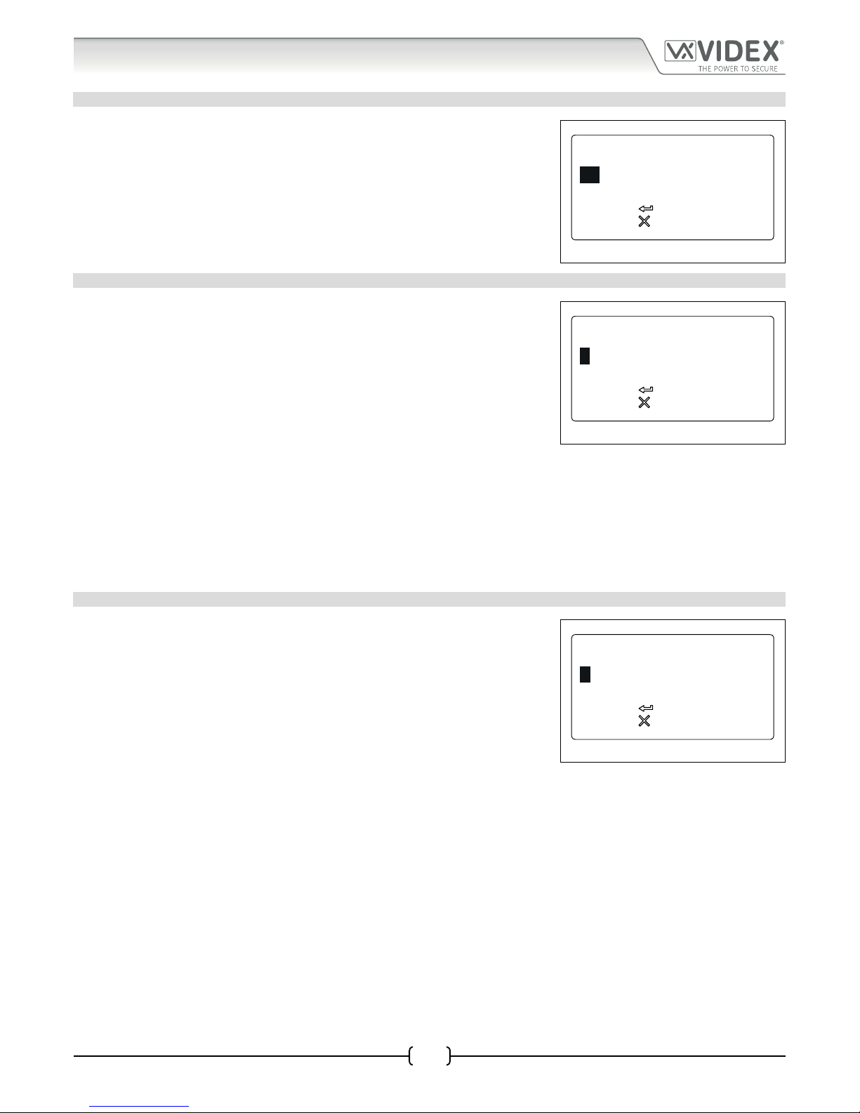
66251750-EN - V1.0 - 05/06/17
40
4000 Series Vandal Resistant Digital GSM - Technical Manual
4000 Series Vandal Resistant Digital GSM Audio Intercom with Proximity
3.4 SPEECHBOARD VOLUME SB VOL
Selecting option 4 from the general settings menu will access the speechboard
volume control screen (refer to Fig.82). On this screen the speechboard volume of the
GSM panel can be adjusted. The current setting will be highlighted on the second line
of the screen (see Fig.82). The default speechboard volume level is set to 85 and can
be adjusted between 0 (low) up to 99 (high). Enter the volume level required then to
conrm and save the setting press the ENTER button and the screen will revert back to
the general settings menu (refer to Fig.78).
Fig. 82
3.5 SPEECHBOARD MODE SB MODE
Selecting option 5 from the general settings menu will access the speechboard mode
screen (refer to Fig.83. From this screen the speechboard mode can be set. The current
setting will be highlighted on the second line of the screen (see Fig.83). Three modes
are available: mode 1, 2 or 3 (see mode options below). The default setting is set to
mode 3. To set the speechboard mode select one of the following:
MODE 1 - Speechboard disabled - the speechboard will be switched OFF (no
speech annunciation will be heard through the panel’s speaker).
MODE 2 - Individual speech playback - the speechboard will be switched
ON. When an apartment is called the panel’s speechboard will playback the
individual numbers that make up an apartment number e.g. if calling apartment
25 the speech will playback “calling two ve”.
MODE 3 - Combined speech playback (default mode) - the speechboard will
be switched ON. When an apartment is called the panel’s speechboard will
playback the combined numbers that make up an apartment number e.g. if
calling apartment 36 the speech will playback “calling thirty six”.
Fig. 83
To conrm and save the setting press the ENTER button and the screen will revert back to the general settings menu (refer to Fig.78).
3.6 PROX BYTE SETTING PROX BYTES
Selecting option 6 from the general settings menu will access the proximity byte
setting screen (refer to Fig.84). From this screen the number of proximity bytes that
the onboard reader checks can be set. The current setting will be highlighted on the
second line of the screen (see Fig.84). There are three byte settings that the panel’s
reader can be set to check for: 2, 3 or 4 bytes (see byte settings below). The default
setting is set to check for 2 bytes. To set the number of bytes select one of the following:
2 Bytes (default setting) - set the panel to check for 2 bytes if the proximity fob/
card has no site code and only a 5 digit user code (955/T fobs or 955/C cards).
3 Bytes - set the panel to check for 3 bytes if the proximity fob/card has a 3 digit
site code and a 5 digit user code (PBX1E fobs or PBX2 cards).
4 Bytes - set the panel to check for 4 bytes for proximity fobs/cards that have a
longer site code and a 5 digit user code.
Fig. 84
To conrm and save the setting press the ENTER button and the screen will revert back to the general settings menu (refer to Fig.78).
to confirm
to cancel
SB VOL:
(0-99)
85
to confirm
to cancel
SB MODE:
(1-3)
3
to confirm
to cancel
PROX BYTES:
(2-4)
2
Programming Screens
Page 41

66251750-EN - V1.0 - 05/06/17
41
4000 Series Vandal Resistant Digital GSM - Technical Manual
4000 Series Vandal Resistant Digital GSM Audio Intercom with Proximity
3.7 PROXIMITY READER ENABLE/DISABLE PROX ENABLE
Selecting option 7 from the general settings menu will access the proximity reader
enable screen (refer to Fig.85). On this screen the proximity reader on the GSM panel
can be switched ON and OFF. The current setting will be indicated on the second line of
the screen with or without a tick in the check box (see Fig.85). By default the onboard
reader will be switched OFF. Enter a “0” (reader switched OFF) to disable the reader or
a “1” (reader switched ON) to enable the reader. To conrm and save the setting press
the ENTER button and the screen will revert back to the general settings menu (refer
to Fig.78).
Fig. 85
3.8 GATE MODE GATE
Selecting option 8 from the general settings menu will access the gate mode screen
(refer to Fig.86). On this screen the gate mode of the panel can be set. The current
setting will be indicated on the second line of the screen with or without a tick in the
check box (see Fig.86). By default the gate mode is set with the check box ticked. To
set the gate mode enter one of the following:
0 - When set in this mode and the panel’s onboard relay is activated the display
will show that the door is open (refer to Fig.107 on page 61). The speech
annunciation (if the speechboard is switched ON) will announce “the door is
open”.
1 - ; When set in this mode and the panel’s onboard relay is activated the display
will show that the gate is open (refer to Fig.108 on page 61). The speech
annunciation (if the speechboard is switched ON) will announce “the gate is
open”.
Fig. 86
To conrm and save the setting press the ENTER button and the screen will revert back to the general settings menu (refer to Fig.78).
4 CODE MENU
From the code menu (refer to Fig.87) it is possible to edit the following access codes:
1. Master code (by default is set to “1111”)
2. Admin code (by default is set to “0000”)
3. Trade code (by default is set to “2222”)
Press the relevant button (1, 2 or 3) to change the required access code.
Fig. 87
4.1 MASTER CODE
Selecting option 1 from the code menu will access the master code screen (refer to
Fig.88). On this screen the master code of the GSM panel can be changed. The current
setting will be highlighted on the second line of the screen (see Fig.88). By default the
master code is set to “1111” and can be changed to any 4 digit number, but must be
kept as a 4 digit number. Enter the new code required then to conrm and save the
setting press the ENTER button and the screen will revert back to the general settings
menu (refer to Fig.78).
Fig. 88
to confirm
to cancel
PROX ENABLE:
(0-1)
GATE:
(0-1)
3
to confirm
to cancel
to exit
1 . MASTER CODE
2 . ADMIN CODE
3 . TRADE CODE
to confirm
to cancel
MASTER CODE
(4 DIGITS)
1111
Programming Screens
Page 42

66251750-EN - V1.0 - 05/06/17
42
4000 Series Vandal Resistant Digital GSM - Technical Manual
4000 Series Vandal Resistant Digital GSM Audio Intercom with Proximity
4.2 ADMIN CODE
Selecting option 2 from the code menu will access the admin code screen (refer to
Fig.89). On this screen the admin code of the GSM panel can be changed. The current
setting will be highlighted on the second line of the screen (see Fig.89). By default the
admin code is set to “0000” and can be changed to any 4 digit number, but must be
kept as a 4 digit number. Enter the new code required then to conrm and save the
setting press the ENTER button and the screen will revert back to the general settings
menu (refer to Fig.78).
Fig. 89
4.3 TRADE CODE
Selecting option 3 from the code menu will access the trade code screen (refer to
Fig.90). On this screen the trade code of the GSM panel can be changed. The current
setting will be highlighted on the second line of the screen (see Fig.90). By default the
trade code is set to “2222” and can be changed to any 4 digit number, but must be kept
as a 4 digit number. Enter the new code required then to conrm and save the setting
press the ENTER button and the screen will revert back to the general settings menu
(refer to Fig.78).
IMPORTANT NOTE: The trade code will only operate when the TRD connection is
shorted to 0V.
Fig. 90
5 TIME SETTINGS MENU
From the time settings menu (refer to Fig.91) it is possible to adjust the following
panel settings:
1. Call time
2. Divert time
3. Open time
4. Aux time
5. Timebands
6. LCD time
Fig. 91
After each menu option the current mode or setting for the panel is shown (on initial install the default modes and settings will be
displayed as shown in Fig.91). Press the relevant button on the panel to select the menu option that requires adjustment.
5.1 CALL TIME
Selecting option 1 from the time settings menu will access the call time screen (refer
to Fig.92). On this screen the call time of the GSM panel can be adjusted. The current
setting will be highlighted on the second line of the screen (see Fig.92). The default call
time is set to 40 seconds and can be adjusted from 1 second up to 255 seconds. Enter
the call time required then to conrm and save the setting press the ENTER button and
the screen will revert back to the time settings menu (refer to Fig.91).
Fig. 92
5.2 DIVERT TIME
Selecting option 2 from the time settings menu will access the divert time screen (refer
to Fig.93). On this screen the divert time of the GSM panel can be adjusted. The current
setting will be highlighted on the second line of the screen (see Fig.93). The default
divert time is set to 15 seconds and can be adjusted from 1 second up to 255 seconds.
Enter the divert time required then to conrm and save the setting press the ENTER
button and the screen will revert back to the time settings menu (refer to Fig.91).
Fig. 93
to confirm
to cancel
ADMIN CODE
(4 DIGITS)
0000
to confirm
to cancel
TRADE CODE
(4 DIGITS)
2222
to exit
1 . CALL TIME:040
2 . DIVERT TIME:015
3 . OPEN TIME:005
4 . AUX TIME:005
5 . TIMEBANDS
6 . LCD TIME:000
to confirm
to cancel
CALL TIME:
(1-255 Sec)
040
to confirm
to cancel
DIVERT TIME:
(1-255 Sec)
015
Programming Screens
Page 43

66251750-EN - V1.0 - 05/06/17
43
4000 Series Vandal Resistant Digital GSM - Technical Manual
4000 Series Vandal Resistant Digital GSM Audio Intercom with Proximity
Programming Screens
5.3 OPEN TIME
Selecting option 3 from the time settings menu will access the open time screen (refer
to Fig.94). On this screen the door/gate open time of the GSM panel can be adjusted.
The current setting will be highlighted on the second line of the screen (see Fig.94).
The default divert time is set to 5 seconds and can be adjusted from 1 second up to
255 seconds. For latching mode set the relay time to 000 seconds. Enter the door/gate
open time required then to conrm and save the setting press the ENTER button and
the screen will revert back to the time settings menu (refer to Fig.91).
Fig. 94
5.4 AUX TIME
Selecting option 4 from the time settings menu will access the aux time screen (refer to
Fig.95). On this screen the time that the auxiliary input stays active for can be adjusted.
The current setting will be highlighted on the second line of the screen (see Fig.95).
The default auxiliary time is set to 5 seconds and can be adjusted from 1 second up to
255 seconds. For latching mode set the relay time to 000 seconds. Enter the aux time
required then to conrm and save the setting press the ENTER button and the screen
will revert back to the time settings menu (refer to Fig.91).
Fig. 95
5.5 TIMEBANDS
Selecting option 5 from the time settings menu will access the 1st timeband screen
(refer to Fig.96). On this screen the timebands can be selected and then programmed
on the next timeband screen. The GSM intercom has 9 programmable timebands (1 -
9). Timeband “0” is the default timeband and is permanently set from 0000 - 2359 and
cannot be adjusted.
To enter a time period for one of the programmable timebands press the relevant
button to make the selection. The display will access the 2nd timeband screen and
the current time period will be highlighted on the second line of the display (refer to
Fig.97).
Enter the time period required (using 24 hour clock notation, e.g. 4:35pm would be
entered as 16:35). To conrm and save the setting press the ENTER button and the
screen will revert back to the timebands list (refer to Fig.96).
It should be noted that the timebands set up on these screens can be assigned to a
specic apartment or apartments (refer to Fig.65 and notes on page 37).
The time settings entered within a timeband is the period of time that an apartment
is available for a call. For any period of time outside of the programmed timeband
and any call from the GSM intercom to the apartment is disabled, e.g. if timeband 1
is set between 10:00 to 14:35 and has been assigned to apartment 1, a call from the
GSM intercom to apartment 1 during this time period will call through ok. Any attempt
to call apartment 1 outside of these times then the GSM intercom will not call the
apartment. During such an event the GSM intercom’s speechboard (if switched ON)
will announce “the phone is switched o, please try later” . The display will indicate this
as shown in Fig.98.
Fig. 96
Fig. 97
Fig. 98
to confirm
to cancel
OPEN TIME:
(1-255 Sec)
005
to confirm
to cancel
AUX TIME:
(1-255 Sec)
005
TIMEBANDS
0> 0000-2359 1> 0000-2359
2> 0000-2359 3> 0000-2359
4> 0000-2359 5> 0000-2359
6> 0000-2359 7> 0000-2359
8> 0000-2359 9> 0000-2359
to exit SELECT 1-9
to confirm
to cancel
TIMEBANDS
1>00:00-23:59
PHONE OFF
Page 44

66251750-EN - V1.0 - 05/06/17
44
4000 Series Vandal Resistant Digital GSM - Technical Manual
4000 Series Vandal Resistant Digital GSM Audio Intercom with Proximity
Programming Screens
5.6 LCD TIME
Selecting option 6 from the time settings menu will access the LCD time screen (refer
to Fig.99). On this screen the switch time of the GSM’s LCD display can be adjusted.
The LCD time of the GSM is the time delay of when the GSM display switches between
the default welcome screen (see Fig.100 for Art.4812 and Fig.101 for Art.4812R on
page 61) and a custom welcome screen or logo which has been uploaded to the panel
using the GSMSK PC software.
The current setting will be highlighted on the second line of the screen (see Fig.99).
The default LCD time is set to 000 (0 seconds = LCD switch time disabled) and can be
adjusted from 0 seconds up to 255 seconds. Enter the LCD switch time required then
to conrm and save the setting press the ENTER button and the screen will revert back
to the time settings menu (refer to Fig.91).
Fig. 99
to confirm
to cancel
LCD TIME:
(1-255 Sec)
000
Page 45

66251750-EN - V1.0 - 05/06/17
45
4000 Series Vandal Resistant Digital GSM Audio Intercom with Proximity
4000 Series Vandal Resistant Digital GSM - Technical Manual
Programming via Text Message
PROGRAMMING THE DIGITAL GSM INTERCOM
Programming the Digital GSM can also be carried out by sending text (SMS) messages.
IMPORTANT NOTE: When you are required to use “ in a text message it is very important to use the correct symbol and not for
example ‘ (or two ‘ single apostrophes side by side which you will see look the same but will be interpreted dierently by the
digital GSM panel).
PROGRAMMING BY TEXT MESSAGE
Programming by text message is a simple way to customise the settings of the digital GSM panel and to add or delete apartment
programming remotely. This can include changing apartments telephone numbers, access codes, names or other settings. If you
have a large number of telephone numbers to enter you may nd programming easier with the GSMSK PC software.
Simply send texts in the following format shown below to the telephone number of the SIM within the digital GSM panel:
<4 DIGIT MASTER CODE> <3 DIGIT FUNCTION CODE> <OPTIONAL DATA> <OPTIONAL ?>
4 DIGIT MASTER CODE This code prevents unauthorised access to the programmable features of the system. The code
must be four digits long but can be any combination using digits 0 – 9. The default master code
is 1111 and will be used for all examples in this manual.
3 DIGIT FUNCTION CODE The 3 digit function code identies the programmable feature to be changed. The code must
be in capital letters. The following table lists the available codes.
DESCRIPTION CODE EXAMPLE SETTINGS DEFAULT PAGE
Programming and storing user
information in a new memory
location
MEM 1111MEMnnn”1stNo.”,”Div1”,
“Div2”,”Div3”,”AptNo.”,”Code”,
DTO,TB,”Name”
* see below n/a 47 - 48
Store or change an apartment
code
STC 1111STCn:”cccccc” n = <apt no.>
cccccc = code
n/a 48
Enable/disable an apartment
DTO setting
STO 1111STOn:O n = <apt no.>
O = 0 or 1
n/a 49
Assign a timeband TB to an
apartment
STB 1111STBn:B n = <apt no.>
B = 1-9
n/a 49
Store or change an apartment
name
STT 1111STTn:”tttttttttttttttt” n = <apt no.>
tttttttttttttttt =
Name. Use a > to
represent a space
n/a 49 - 50
Store a primary telephone no. STN 1111STNn:”yyyyyyyyyyy” n = <apt no.>
yyyyyyyyyyy =
telephone no. 30
digits max.
n/a 50
Store divert 1 telephone no. STD 1111STDn:”yyyyyyyyyyy” n/a 50
Store divert 2 telephone no. STE 1111STEn:”yyyyyyyyyyy” n/a 50
Store divert 3 telephone no. STF 1111STFn:”yyyyyyyyyyy” n/a 50
Set call time SPT 1111SPTnnn nnn = 001 - 255 040 (40s) 51
Set relay time RLT 1111RLTnnn nnn = 001 - 255 005 (5s) 51
Set auxiliary output AO time A1T 1111A1Tnnn nnn = 001 - 255 005 (5s) 51
Set auxiliary output AO mode A1M 1111A1Mnnn nnn = 000 - 001 001 51
Keep connection facility NOD 1111NODnnn nn = 01 - 99 0 (disabled) 51 - 52
Divert time DIT 1111DITnn nn = 01 - 99 15 (15s) 52
Check GSM signal strength SIG 1111SIG? n/a n/a 52
Check software version VER 1111VER? n/a n/a 52
Forced dial/dial a number DLE 1111DLE”123” n/a n/a 52
Change 4 digit master code CDE 1111CDE1234 Any 4 digits 1111 53
Change 4 digit admin code CDA 1111CDA1234 Any 4 digits 2222 53
Change 4 digit trade code CDT 1111CDT1234 Any 4 digits 0000 53
Trigger the relay RLY 1111RLY n/a n/a 53
Trigger auxiliary output AO A1O 1111A1O n/a n/a 53
Page 46

66251750-EN - V1.0 - 05/06/17
46
4000 Series Vandal Resistant Digital GSM Audio Intercom with Proximity
4000 Series Vandal Resistant Digital GSM - Technical Manual
Programming via Text Message
Store balance check dial string SDL 1111SDL”*#1345#” n/a n/a 53
Check credit balance BAL 1111BAL? n/a n/a 53 - 54
Store a master telephone no. STM 1111STM”07771234567” n/a n/a 54
Latch the relay RLA 1111RLA n/a n/a 54
Unlatch the relay RUL 1111RUL n/a n/a 54
Latch auxiliary output AO A1L 1111A1L n/a n/a 54
Unlatch the auxiliary output AO A1U 1111A1U n/a n/a 54
Store a time band TBA 1111TBAn”06002300” HHMMHHMM 00002359 55
Check/set date & time CLK 1111CLK”yy/mm/dd,hh:mm”? yy/mm/dd,hh:mm n/a 55 - 56
Silent dialling mode AUE 1111AUEnnn nnn = 000 or 001 001 56
Enable dial 0 on answer function EDZ 1111EDZnnn? nnn = 000 or 001 000 56
Enable the # (hash) function ED# 1111ED#nnn? nnn = 000 or 001 000 56
Enable proximity reader EPR 1111EPRnnn? nnn = 000 or 001 000 56
Proximity number of bytes to
check
PBY 1111PBYnnn? nnn = 002, 003 or
004
002 57
Store/query a proximity fob/card FOB 1111FOBnnn”site”,”user” nnn = 0000 - 1999 n/a 57 - 58
Disable (001), enable individual
(002) or enable combined (003)
speech board
SBM 1111SBMnnn? nnn = 001, 002 or
003
003 58
Set speech board volume SBV 1111SBVnnn? nnn = 000 - 099 75 58
Find a telephone number FDT 1111FDT” number or ends in”? n/a n/a 58 - 59
Find a fob or card FDF 1111FDF”nnnnn”? n/a n/a 59
Door or Gate GAT 1111GATnn? 00 or 01 n/a 59
Shutdown and Restart RBT 1111RBT n/a n/a 60
Initiate a special command PRG 1111PRG(command) AT commands n/a 60
AT command to send at start up AT1 1111AT1”ATxxxxxx”? Any AT command n/a 60
AT command to send at start up AT2 1111AT2”ATxxxxxx”? Any AT command n/a 60
AT command to send at start up AT3 1111AT3”ATxxxxxx”? Any AT command n/a 60
OPTIONAL DATA The optional data will vary depending on the command used. It may be a telephone number,
a time setting or may not be used at all. For more information refer to the following command
settings.
OPTIONAL ? Most of the commands suppor t the ? feature. When this is added to the end of the text message,
a conrmation text message will be sent back to the sender indicating the new data has been
received and stored.
When sending text messages there may be a delay from when you send the message to when it is received by the digital GSM
intercom depending on how congested the network is. If you are at the door panel when sending the message you will here a single
beep from the digital GSM intercom to indicate it has received the message.
Page 47

66251750-EN - V1.0 - 05/06/17
47
4000 Series Vandal Resistant Digital GSM Audio Intercom with Proximity
4000 Series Vandal Resistant Digital GSM - Technical Manual
PROGRAMMING AND STORING USER INFORMATION IN A NEW MEMORY LOCATION MEM
The memory location in the digital GSM is simply a position within the GSM’s internal memory where the user’s apartment information
is stored. Up to 500 user’s can be stored in the digital GSM (memory locations 000 - 499).
There are 9 parts of user information that is stored in a memory location (also refer to pages 36 - 38):
1. Apartment number (APT);
2. Door/gate access code (CODE);
3. Dial to open number/setting (DTO/STO);
4. Timeband assignment (TB);
5. Username (NAME);
6. Primary telephone number (TEL1/STN);
7. First divert number (TEL2/Div1/STD);
8. Second divert number (TEL3/Div2/STE);
9. Third divert number (TEL4/Div3/STF).
IMPORTANT NOTE: It is important to remember that before any specic user information can be changed, e.g. apartment
number, telephone numbers etc., these details must rst be stored in a memory location in the digital GSM. Without this initial
information no changes can be made as there would be no user information stored in the GSM’s memory to change or edit.
To store a user’s information in a memory location the SMS message must be sent in the following format:
1111MEMnnn”TEL1”,”TEL2”,”TEL3”,”TEL4”,”APT”,”CODE”,DTO,TB,”NAME”?
where:
• 1111 = 4 digit code;
• MEM = 3 digit function code;
• nnn = memory location (from 000 - 499);
• TEL1 = primary telephone number (30 digits maximum);
• TEL2 = rst divert number Div1 (30 digits maximum);
• TEL3 = second divert number Div2 (30 digits maximum);
• TEL4 = third divert number Div3 (30 digits maximum);
• APT = apartment number (maximum of 6 digits including letters A - F);
• CODE = door/gate access code (maximum of 6 digits);
• DTO = dial to open enable (enter 1 to enable, leave blank or enter 0 to disable, also refer to page 37);
• TB = timeband assignment (from 1 - 9, leave blank or enter 0 for default timeband, also refer to pages 37 and 43);
• NAME = username (maximum of 16 characters where the > character can be used to insert a space between characters
or words).
Where shown, (in the example above) the quotation marks “ and commas , must be included as part of the line of programming text
with no spaces. The ? at the end of the message is optional if a conrmation text is required.
The following text messages that can be sent to the digital GSM to program/store are as follows:
1111MEMnnn”TEL1”,”TEL2”,”TEL3”,
”TEL4”,”APT”,”CODE”,DTO,TB,
”NAME”?
Store the primary telephone number TEL1, rst divert TEL2, second divert TEL3, third
divert TEL4, apartment number APT, door/gate access code CODE, dial to open enable
DTO, timeband assignment TB and username NAME in memory location nnn. A text
message will be sent to the sender with the stored information for that memory location.
Where nnn = memory location 000 - 499.
1111MEMnnn? Query the apartment details stored in memory location nnn, where nnn = memory
location 000 - 499.
Programming via Text Message
Page 48

66251750-EN - V1.0 - 05/06/17
48
4000 Series Vandal Resistant Digital GSM Audio Intercom with Proximity
4000 Series Vandal Resistant Digital GSM - Technical Manual
The following example shows how to program a user’s details:
Example 1: To program the following user’s information: primary telephone number 01912243174, rst divert 07791123456, second
divert 07897654321, third divert 07999532641, apartment no. 123, door/gate access code 654321, dial to open enabled,
timeband 3, username Videx Tech in memory location 150 and receive a conrmation text, the following SMS message can
be sent.
1111MEM150”01912243174”,” 07791123456”,” 07897654321”,” 07999532641”,”123”,”654321”,1,3,”Videx>Tech”?
Note that quotation marks “ and commas , are used where appropriate and the > character is used to insert a space
between the words Videx and Tech for the username. The optional ? is included at the end so a conrmation text is
sent back to the sender.
The digital GSM will store the above information in memory location 150 and send the following conrmation text
back to the sender:
MEM 150 APT = 123 CODE = 654321
DTO = 1 TB = 3 NAME = Videx Tech
TEL = 01912243174 TEL (DIVERT 1) = 07791123456
TEL (DIVERT 2) = 07897654321 TEL (DIVERT 3) = 07999532641
OK VIDEX GSM
Using the same MEM programming command it is also possible to change all or only part of the user’s details as well as delete part
of a user’s details that may no longer be required. To leave a particular user detail or setting unchanged simply don’t enter anything
in that section of the command but remember to add a comma , . To delete part of the user’s details simply use two quotation marks
““ next to each other in that section of the MEM programming command.
Using the same user details from the previous example the next example shows how to change and delete only part of the user’s
details in memory location 150.
Example 2: If the user only needs to delete the door/gate access code, delete the third divert number and no longer requires the
dial to open feature enabled and receive a conrmation text, the following SMS message can be sent.
1111MEM150,,,””,,””,0,,?
Note that two quotation marks ““ are used next to each other to delete a particular detail and commas , are used
where details remain unchanged. The optional ? is included at the end so a conrmation text is sent back to the
sender.
The digital GSM will amend the above information in memory location 150 and send the following conrmation text
back to the sender:
MEM 150 APT = 123 CODE =
DTO = 0 TB = 3 NAME = Videx Tech
TEL = 01912243174 TEL (DIVERT 1) = 07791123456
TEL (DIVERT 2) = 07897654321 TEL (DIVERT 3) =
OK VIDEX GSM
STORE OR CHANGE AN APARTMENT CODE STC
Each apartment can have a unique door/gate access code programmed which can be a maximum of up to 6 digits (also refer to the
notes door/gate access code on page 37). The following text messages can be used to store/change, delete and query the access
code stored for an apartment.
1111STCn:”cccccc” Store a door/gate access code cccccc for apartment n, where cccccc = code (up to 6 digits
max.) and n = apartment number.
1111STCn:”cccccc”? Store a door/gate access code cccccc for apartment n, where cccccc = code (up to 6 digits
max.) and n = apartment number. Also send a conrmation text back to the sender.
1111STCn:”” Delete a door/gate access code cccccc for apartment n, where cccccc = code (up to 6
digits max.) and n = apartment number.
1111STCn:””? Delete a door/gate access code cccccc for apartment n, where cccccc = code (up to 6
digits max.) and n = apartment number. Also send a conrmation text back to the sender.
1111STCn:? Query the door/gate access code stored for apartment n, where n = apartment number.
Also send a conrmation text back to the sender.
IMPORTANT NOTE: Remember that the apartment number n can be up to 6 digits in length including letters A - F.
Programming via Text Message
Page 49

66251750-EN - V1.0 - 05/06/17
49
4000 Series Vandal Resistant Digital GSM Audio Intercom with Proximity
4000 Series Vandal Resistant Digital GSM - Technical Manual
ENABLE/DISABLE AN APARTMENTS DTO DIAL TO OPEN SETTING STO
Each apartment can have their programmed telephone numbers set up as dial to open numbers. Once this feature is enabled for an
apartment all the numbers stored for that apartment (primary and 3 divert numbers) will be set as dial to open numbers. If a user
calls from any of the stored numbers the digital GSM will see that they are dial to open numbers and drop the call but activate the
onboard relay to trigger the door/gate.
IMPORTANT NOTE: It is important to switch OFF voicemail and automatic SMS features on the SIM card in the digital GSM when
using this feature (see the ‘Forced Dial’ DLE section for more details). Also note that it will not be possible to use the dial in to
speak facility from a number stored to release the door/gate when dialling in (door release takes priority, refer to the priority
function table on page 64).
Please also note it is important that the numbers stored, when dialling in to release the door/gate, must have any “caller ID” or
“withheld number” function switched OFF on the telephone/mobile that is making the call to the digital GSM. If this feature is
not switched OFF the GSM intercom will not recognise the caller’s number and simply end the call with no action taken.
By default this feature is disabled (switched OFF). The following text messages can be used to enable or disable the dial to open
feature.
1111STOn:O Set the dial to open feature O for apartment n, where n = apartment number, O = 0
disabled (switched OFF) or O = 1 enabled (switched ON).
1111STOn:O? Set the dial to open feature O for apartment n, where n = apartment number, O = 0
disabled (switched OFF) or O = 1 enabled (switched ON). Also send a conrmation text
back to the sender.
1111STOn:? Query the dial to open setting for apartment n, where n = apartment number, O = 0
disabled (switched OFF) or O = 1 enabled (switched ON). Also send a conrmation text
back to the sender.
ASSIGN A TIMEBAND TB TO AN APARTMENT STB
Each apartment can have a timeband TB assigned to it (also refer to notes on page 37 and 43 on setting up timebands). By default
timeband 0 is already assigned to the apartment (timeband 0 is set to 00:00 - 23:59). There are 9 other programmable timebands
(1 - 9) available for an apartment to be assigned to and each apartment can only be set to one timeband at any one time.
The following text messages can be used to assign (set) a timeband to an apartment.
1111STBn:B Set the timeband B to an apartment n, where n = apartment number, B = timeband 1 - 9.
1111STBn:B? Set the timeband B to an apartment n, where n = apartment number, B = timeband 1 - 9.
Also send a conrmation text back to the sender.
1111STBn:? Query the timeband set for an apartment, where n = apartment number. Also send a
conrmation text back to the sender.
STORE OR CHANGE AN APARTMENT NAME STT
An apartment name (usually the user’s name) can be programmed into the digital GSM. The following text messages can be used to
store, change , delete or query an apartment name (also refer to notes on page 37). The apartment name can be up to a maximum
of 16 characters long.
1111STTn:”tttttttttttttttt” Store an apartment name (username) tttttttttttttttt for apartment n, where n = apartment
number, tttttttttttttttt = apartment name (16 characters max.).
1111STTn:”tttttttttttttttt”? Store an apartment name (username) tttttttttttttttt for apartment n, where n = apartment
number, tttttttttttttttt = apartment name (16 characters max.). Also send a conrmation
text back to the sender.
1111STTn:”” Delete the apartment name (username) for apartment n, where n = apartment number.
1111STTn:””? Delete the apartment name (username) for apartment n, where n = apartment number.
Also send a conrmation text back to the sender.
1111STTn:? Query the apartment name (username) stored for apartment number n, where =
apartment number. Also send a conrmation text back to the sender.
Programming via Text Message
Page 50
66251750-EN - V1.0 - 05/06/17
50
4000 Series Vandal Resistant Digital GSM Audio Intercom with Proximity
4000 Series Vandal Resistant Digital GSM - Technical Manual
The > symbol can be used to insert a space between characters or words, for example:
Example: To program the username Mr Smith for apartment 321and receive a conrmation text, the following SMS message can be
sent to the digital GSM.
1111STT321:”Mr>Smith”?
Note that quotation marks “ and a colon : are used where appropriate and the > character is used to insert a space
between the words Mr and Smith for the name. The optional ? is included at the end so a conrmation text is sent
back to the sender.
The digital GSM will store the above username for apartment 321 and send the following conrmation text back to
the sender:
APT = 321 NAME = Mr Smith
OK VIDEX GSM
STORE OR CHANGE THE APARTMENT TELEPHONE NUMBERS STN, STD, STE AND STF
Telephone numbers can be stored for the 500 available apartments. Each apartment can have up to four telephone numbers (if the
rst is busy or not answered in a certain time it can call a 2nd, 3rd and 4th number). The STN code stores the rst number (primary
telephone number) when the apartment is called. The STD (Div1), STE (Div2) and STF (Div3) codes stores the diverted telephone
numbers if the rst is busy or not answered (the digital GSM will divert to the 2nd number then divert to the 3rd number and nally
the 4th number). The text messages to store, change or check numbers are as follows, replace STN with STD, STE or STF when
storing/changing divert numbers.
1111STNn:”yyyyyyyyyyy” Store the primary telephone number yyyyyyyyyyy for apartment number n.
1111STNn:”yyyyyyyyyyy”? Store the telephone number yyyyyyyyyy for apartment number n and send a conrmation
text message to conrm storage of new number.
1111STNn:? Query the telephone number stored for apartment number n. A text message will be sent
to the sender with the stored number for that location.
1111STNn:”” Delete the telephone number stored for apartment number n.
1111STNn:””? Delete the telephone number stored for apartment number n. A text message will be
sent to the sender with the delete conrmation for that location.
n is an apartment number which can be made from up to a maximum of 6 digits including letters A - F. The telephone number
yyyyyyyyyyy can be a maximum of 30 digits. For example: to store the number 01912243174 for apartment 123 and include
three divert numbers (if that one is not answered or busy, Div1, Div2 and Div3) of 01912241558, 07771234567 and 01912241559
respectively, the following SMS messages would be sent to the digital GSM:
1111STN123:”01912243174”
1111STD123:”01912241558”
1111STE123:”07771234567”
1111STF123:”01912241559”
To query any of these numbers for apartment 123 the following SMS messages would be sent to the digital GSM:
1111STN123:?
1111STD123:?
1111STE123:?
1111STF123:?
Programming via Text Message
Page 51

66251750-EN - V1.0 - 05/06/17
51
4000 Series Vandal Resistant Digital GSM Audio Intercom with Proximity
4000 Series Vandal Resistant Digital GSM - Technical Manual
SET CALL TIME SPT
The call time is the maximum time in seconds that a call can last before the GSM panel automatically clears the call down. The time
can be from 1 second up to 255 seconds and begins from when the call is made from the panel. The default time is 40 seconds. The
following messages are used to set/check the maximum call time (also refer to notes on page 42).
1111SPTnnn Store the call time nnn seconds, where nnn is the time in seconds.
1111SPTnnn? Store the call time nnn seconds, where nnn is the time in seconds. Also send a conrmation
text back to the sender.
1111SPT? Query the current stored call time. A text message will be sent back to the sender showing
the stored time.
SET RELAY TIME RLT
The relay time can be set from 001 – 255 seconds or latching. To set the relay time for latched mode set the relay time to 000. In latch
mode the relay will stay energised until the command is sent again (also refer to notes on page 43).
1111RLTnnn Store the relay time nnn = time in seconds (e.g. nnn = 005, time = 5 seconds).
1111RLTnnn? Store the relay time nnn = time in seconds. Also send a conrmation text back to the
sender.
1111RLT? Query the current stored relay time. A text message will be sent back to the sender
showing the stored relay time.
SET AUXILIARY OUTPUT AO TIME A1T, FOR A1M MODE = 001 OR 002 ONLY
The auxiliary output AO time can be set from 001 - 255 seconds or latching. To set the AO output time for latched mode set the
auxiliary time to 000. In latch mode the AO output will stay triggered until the relevant command is sent again to unlatch the output
(e.g. sending text message 1111A1O to the digital GSM) or during a call by pressing 6 on the telephone to reset the AO output. The
latching mode option is only available when the AO output mode, A1M, is set to mode 001. Please refer to the A1M modes below
for more details (also refer to notes on page 43).
1111A1Tnnn Store the AO time nnn = time in seconds (e.g. nnn = 005, time = 5 seconds).
1111A1Tnnn? Store the AO time nnn = time in seconds. Also send a conrmation text back to the sender.
1111A1T? Query the current stored AO time. A text message will be sent back to the sender showing
the stored AO time.
SET AUXILIARY OUTPUT AO MODE A1M, MODES 000 002
The auxiliary output AO has three modes that can be set (also see additional notes on page 39):
Call Activated: nnn = 000
AO output will activate when a call begins and deactivate when a call ends. See example on page 13.
User Activated: nnn = 001 (default mode)
To activate the AO output press 6 on the telephone during a call or sending the text message 1111A1O to the digital GSM. The
auxiliary output can also be activated by triggering the auxiliary input AI. See example on page 13.
Call Activated (Timed): nnn = 002
AO output will activate when a call begins and deactivate when the auxiliary output time (A1T) expires. See example on page 14.
1111A1Mnnn Store the AO mode nnn = 000 - 002 (see modes above).
1111A1Mnnn? Store the AO mode nnn = 00n - 002 (see modes above). Also send a conrmation text
back to the sender.
1111A1M? Query the current stored AO mode (see modes above). A text message will be sent back
to the sender showing the stored AO mode.
KEEP CONNECTION FACILITY NOD
In the event the digital GSM intercom panel is not used for long periods of time it could be possible that the network disconnects
it. To prevent this from happening it is possible to program a time period (from 001 – 365 days or disabled 000) to wait before the
digital GSM intercom makes a short call to refresh the connection to the network. This time period is reset after each call made on
the system and will only happen if the full time period elapses without any incoming or outgoing calls.
Programming via Text Message
Page 52

66251750-EN - V1.0 - 05/06/17
52
4000 Series Vandal Resistant Digital GSM Audio Intercom with Proximity
4000 Series Vandal Resistant Digital GSM - Technical Manual
1111NODnnn Store the time nnn = time in days (e.g. nnn = 007, time = 7 days).
1111NODnnn? Store the time nnn = time in days. Also send a conrmation text back to the sender.
1111NOD? Query the current stored time. A text message will be sent back to the sender showing
the stored time.
DIVERT TIME DIT
The divert time is the number of seconds to wait for a call to be answered before diverting to the 2nd, 3rd and 4th number. The
default time is 15 seconds (the count down begins from when an apartment is called, but is refreshed when the telephone begins
to ring) and can be set from 001 – 255 seconds (also see notes on page 42).
1111DITnnn Store the divert time nnn = time in seconds (e.g. nnn = 015, time = 15 seconds).
1111DITnnn? Store the divert time nnn = time in seconds. Also send a conrmation text back to the
sender.
1111DIT? Query the current stored divert time. A text message will be sent back to the sender
showing the stored divert time.
IMPORTANT NOTE: Once the divert time is set on the digital GSM panel it is set for the same time for all divert numbers for all
apartments stored in the digital GSM intercom. Each apartments divert numbers cannot have individual divert times set, e.g. if
the divert time is set for 10 seconds then the divert time for apartment 1 will be the same as the divert time for apartment 321
and so on. Apartment 1 will not have a dierent divert time to apartment 321 it will be the same.
CHECK GSM SIGNAL STRENGTH SIG
At any time the signal strength of the digital GSM can be checked (also see notes on understanding the signal strength on page 64).
It is advisable that when the digital GSM is rst setup and before any other programming is carried out to check the signal strength
of the GSM intercom. If the signal strength is too low the digital GSM may not operate properly and therefore the GSM antenna will
need to be repositioned to increase the signal strength. Use the following command to check the signal strength.
1111SIG? Check the signal strength of the digital GSM intercom and send a conrmation text back
to the sender.
CHECK SOFTWARE VERSION VER
It is possible to check the current version of software on the digital GSM. This may be necessary to see if an update is required for any
additional features or updates on the digital GSM which may be included on later versions. Use the following command to check
the software version.
1111VER? Check the software version of the digital GSM intercom and send a conrmation text back
to the sender.
FORCED DIAL/DIAL A NUMBER DLE
A useful feature of the digital GSM panel is its ability to call a number sent to it in a text message. This feature can be used when
setting up the SIM card. For example, disabling the voicemail facility or disabling automatic SMS messages or missed calls. Any
number up to 15 digits can be called and the call will last for a maximum of 40 seconds. The example below would switch o
voicemail on a Vodafone SIM card. Substitute the Vodafone number for other service providers.
1111DLE”1210” Dial 1210 for the intercom panel.
For UK customers other useful numbers which can be used with this feature are as follows. For other countires please check the
service provider’s web sites for other useful codes.
IMPORTANT NOTE: Although the following codes have been conrmed to work with the GSM intercom Videx oers no guarantee
that other codes from other network providers will work.
Vodafone O
2
DISABLE VOICEMAIL 1210 1760
DISABLE TEXT ALERTS #148# 1760
IMPORTANT NOTE: Disabling voicemail and text alerts is very important as there is no way to retrieve either of these services
from the digital GSM panel. Disabling these features will also prevent the intercom panel switching to voicemail or sending a
text when dialling in from another phone.
Programming via Text Message
Page 53

66251750-EN - V1.0 - 05/06/17
53
4000 Series Vandal Resistant Digital GSM Audio Intercom with Proximity
4000 Series Vandal Resistant Digital GSM - Technical Manual
CHANGE THE 4 DIGIT MASTER CODE CDE
The four digit master code (by default = 1111) can be any combination of numbers between 0 - 9, but must be 4 digits long. The
code allows access to the full programming menu and must be used when sending text messages to the digital GSM. Use the
following message to change the four digit master code (also see notes on page 41).
1111CDEnnnn Change the 4 digit master code to nnnn (where nnnn = new 4 digit master code).
CHANGE THE 4 DIGIT ADMIN CODE CDA
The four digit admin code (by default = 0000) can be any combination of numbers between 0 - 9, but must be 4 digits long. The code
allows access to the admin menu and must be used when sending text messages to the digital GSM. Use the following message to
change the four digit admin code (also see notes on page 42).
1111CDAnnnn Change the 4 digit admin code to nnnn (where nnnn = new 4 digit admin code).
CHANGE THE 4 DIGIT TRADE CODE CDT
The four digit trade code (by default = 2222) can be any combination of numbers between 0 - 9, but must be 4 digits long. The trade
code can only be used when a timeclock has been connected to the trade input (TRD terminal) on the digital GSM when a trade
code facility is required. Use the following message to change the four digit trade code (also see notes on page 42).
1111CDTnnnn Change the 4 digit trade code to nnnn (where nnnn = new 4 digit trade code).
TRIGGER THE RELAY RLY
There are several ways to trigger the digital GSM relay. The rst is to press button 3 on the telephone during a call and the relay will
operate for the programmed time. Another way is to send the following text message.
1111RLY Operate the digital GSM relay (for the programmed time).
1111RLY? Operate the digital GSM relay (for the programmed time) and send a conrmation text
back to the sender.
TRIGGER AUXILIARY OUTPUT AO A1O
It is possible to trigger the auxiliary output AO for the programmed output time (A1T, also refer to page 43 for setting A1T time).
Please note that this method of triggering auxiliary output AO is only possible when the A1M mode has been set to mode 001, also
refer to page 39 and the examples on pages 13 and 14. Triggering the auxiliary output can be achieved by shorting terminals AI
and GND on the digital GSM intercom, pressing button 6 on the telephone during a call or by sending the following text message
to the digital GSM panel.
1111A1O Trigger auxiliary output AO (for the programmed time).
1111A1O? Trigger auxiliary output AO (for the programmed time) and send a conrmation text back
to the sender.
STORE BALANCE CHECK DIAL STRING SDL
Several network providers oer the facility to check available balance on their pay as you go taris. For example, on Vodafone the
string is *#1345# and on O2 the string is *#10#. Other networks may also have this feature. Since the digital GSM intercom will not
know the details of the network provider’s SIM card which you have inserted it will be necessary to store the correct string in order
to use the credit balance check features.
1111SDL”*#1345#” Store the balance check string for a Vodafone pay as you go.
1111SDL”*#10#” Store the balance check string for an O2 pay as you go.
IMPORTANT NOTE: Videx are only aware of the balance check dial string codes for the network providers mentioned above.
Check dial string codes for other networks are currently unavailable at this time. Please also note that this programming
function is only applicable for pay as you go SIM cards.
CHECK CREDIT BALANCE BAL
The balance can only be checked if the correct balance check string has previously been stored using the SDL code explained
above. At any point the user will be able to send the following text message and the digital GSM intercom will reply with the current
balance stored on the SIM card.
1111BAL? Check current balance of the SIM in the digital GSM intercom and send a conrmation
text back to the sender.
Programming via Text Message
Page 54

66251750-EN - V1.0 - 05/06/17
54
4000 Series Vandal Resistant Digital GSM Audio Intercom with Proximity
4000 Series Vandal Resistant Digital GSM - Technical Manual
In addition to this feature the digital GSM also has the facility to monitor the available credit and then text the user to inform them
when the credit has fallen below £5.00, €5.00 or $5.00. It will then remind the user with another text after every 5 calls until the
credit has either increased or if it runs out.
To use this feature, the following settings must rst be made:
A Pay As You Go SIM card from a provider that oers this service (Vodafone, O2) must be used.
The correct balance check string must be stored using the SDL code (see store balance check dial string).
A mobile phone number that is to receive the ‘balance low’ text must be stored in the master telephone number location using the
STM code (refer to ‘store master telephone number’ feature below).
STORE A MASTER TELEPHONE NUMBER STM
The master telephone number is the number which will receive automatic balance updates when the balance gets low (if this
feature is setup). To store a master telephone number the following programming texts can be sent to the digital GSM intercom.
1111STM”yyyyyyyyyyy” Store the telephone number yyyyyyyyyyy.
1111STM”yyyyyyyyyyy”? Store the telephone number yyyyyyyyyyy and send a conrmation text back to the
sender.
1111STM? Query the master telephone number stored. A text message will be sent to the sender with the
stored master telephone number.
1111STM”” Delete the master telephone number stored.
1111STM””? Delete the master telephone number stored and send a conrmation text back to the
sender.
LATCH THE RELAY RLA
It is possible to latch the digital GSM relay closed. This function is particularly useful if the GSM relay is connected to a gate controller
and the user wishes to ‘hold open’ the gate. The following text message can be sent to the digital GSM intercom.
1111RLA Latch the digital GSM relay to the C/NO position.
1111RLA? Latch the digital GSM relay to the C/NO position and send a conrmation text back to the
sender.
UNLATCH THE RELAY RUL
If the digital GSM intercom relay has been latched it is possible to unlatch the relay with the following text message.
1111RUL Unlatch the digital GSM relay back to the C/NC position.
1111RUL? Latch the digital GSM relay to the C/NC position and send a conrmation text back to the
sender.
IMPORTANT NOTE: The digital GSM relay can also be unlatched by pressing 3 on the telephone during a call.
LATCH AUXILIARY OUTPUT AO A1L
Auxiliary output AO, like the onboard relay, can be latched. To latch auxiliary output AO the following text message can be sent to
the digital GSM intercom.
1111A1L Latch auxiliary output AO.
1111A1L? Latch auxiliary output AO and send a conrmation text back to the sender.
UNLATCH AUXILIARY OUTPUT AO A1U
Auxiliary output AO can also be unlatched. To unlatch auxiliary output AO the following text message can be sent to the digital
GSM intercom.
1111A1U Unlatch auxiliary output AO.
1111A1U? Unlatch auxiliary output AO and send a conrmation text back to the sender.
Programming via Text Message
Page 55

66251750-EN - V1.0 - 05/06/17
55
4000 Series Vandal Resistant Digital GSM Audio Intercom with Proximity
4000 Series Vandal Resistant Digital GSM - Technical Manual
STORE A TIMEBAND TBA
IMPORTANT NOTE: This feature relies on the network providers time zone setting and also if they support NITZ (Network Identity
and Time Zone). First check the time/date is correct by sending the SMS message 1111CLK? (also refer to check intercoms time
& date feature below). If the time/date returned is incorrect, it maybe that they do not support it. The clock can be set manually
but any power cut will result in the time and date being lost unless battery backup is included.
The timeband feature allows a call to an apartment to be enabled for a specic time period. Remember there are 9 programmable
timebands (1 - 9) available (also refer to notes on page 43). By default timeband 0 is set to 00:00 - 23:59 and cannot be re-programmed,
any apartment assigned to timeband 0 will enable a call to go through to the apartment. Once a timeband has been programmed it
can then be assigned to an apartment (see notes on page 37 and programming notes assign a timeband, STB, on page 49).
Remember to always use 24hr clock notation and also ensure the start time is earlier than the stop time. Use the following text
messages to store, query and delete a timeband.
1111TBAn”HHMMHHMM” Store the time period HHMMHHMM for timeband n (where n = timeband 1 - 9, the rst
HHMM is the start time and the second HHMM is the stop time.
1111TBAn”HHMMHHMM”? As above but also send a conrmation text back to the sender with the stored setting.
1111TBAn? Query the time period programmed for timeband n (where n = timeband 1 - 9). A text
message will be sent to the sender with the stored HHMMHHMM time period for timeband
n.
1111TBAn”” Delete the programmed time period for timeband n (where n = timeband 1 - 9).
1111TBAn””? Delete the programmed time period for timeband n (where n = timeband 1 - 9) and
conrm deletion of the timeband.
The following example shows how to program a timeband:
Example: Programming a time period to start from 6:00am until 11:30pm for timeband 1. Store the time using the format
HHMMHHMM. The rst HHMM is the start time (i.e. receive calls from 0600, 6am in the morning) and the second
HHMM is the stop time (i.e. calls will be received up until 2330, 11:30pm at night, as soon as the clock reaches 2331,
11:31pm calls to the apartment will stop).
1111TBA1”06002330”?
Note that quotation marks “ are used where appropriate and 24hr clock notation is used. The optional ? is included
at the end so a conrmation text is sent back to the sender.
The digital GSM will store the above time period for timeband 1 and send the following conrmation text back to
the sender:
TB 1 06002330
OK VIDEX GSM
Any apartment which is then assigned to timeband 1 will only receive calls between the hours of 06:00 in the morning
until 23:30 at night, calls after 23:30, i.e. 23:31 onwards will stop.
CHECK/SET DATE & TIME CLK
The check date and time feature relies on the network providers time zone setting (also refer to important note above). After a SIM
has been placed into the digital GSM intercom and powered up the SIM will attempt to register with the network and automatically
synchronise with the network providers time zone setting. The following text messages can be sent to the digital GSM to check and
set the current time and date. The date and time format is as follows: yy/mm/dd, hh:mm, where yy = year, mm = month, dd = date
and hh = hour, mm = minutes.
1111CLK? Check current time & date and send a conrmation text back to the sender.
1111CLK”yy/mm/dd,hh:mm” Set current time & date.
1111CLK”yy/mm/dd,hh:mm”? Set current time & date and send a conrmation text back to the sender.
Example: Setting the current time & date to 10:05am, 24th April 2017, the following text can be sent to the digital GSM intercom:
1111CLK”17/04/24,10:05”?
Note that quotation marks “ are used where appropriate. The optional ? is included at the end so a conrmation text
is sent back to the sender.
Programming via Text Message
Page 56
66251750-EN - V1.0 - 05/06/17
56
4000 Series Vandal Resistant Digital GSM Audio Intercom with Proximity
4000 Series Vandal Resistant Digital GSM - Technical Manual
The digital GSM intercom will reply with the following text:
CLK = 17/04/24, 10.05
OK VIDEX GSM
SILENT DIALLING MODE AUE
When the digital GSM is calling the telephone number stored there is a choice of either hearing the ringing noise from the intercom
panel or just hearing beeps to indicate a call is in progress.
• Ringing heard during calling: nnn = 001
• Beeps heard during calling: nnn = 000
The following text messages can be sent to the digital GSM intercom to enable (000), disable (001) or query the setting of the silent
dialling feature.
1111AUEnnn Set the silent dialling mode nnn (where nnn = 001 or 000).
1111AUEnnn? Set the silent dialling mode nnn (where nnn = 001 or 000) and send a conrmation text
back to the sender.
1111AUE? Query the current mode stored. A text message will be sent back to the sender conrming
which silent dialling mode has been set.
ENABLE THE DIAL ‘0’ ON ANSWER FUNCTION EDZ
When enabled this feature allows an incoming call to an apartment to be diverted to the programmed divert telephone number
if the ‘0’ button on the telephone has not been pressed after answering the call. This can be useful if the user’s number has an
answerphone service (or answer machine) and they do not want the call to be answered by this service or if the primary number
(mobile no.) is switched o.
The default for this function is disabled (set to 000). The following texts can be used to enable or disable this function.
1111EDZnnn Set the dial ‘0’ function nnn: 001 or 000 (001 = enable, 000 = disabled).
1111EDZnnn? Set the dial ‘0’ function nnn: 001 or 000 (001 = enable, 000 = disabled) also send a
conrmation text back to the sender.
1111EDZ? Query the dial ‘0’ mode set.
When this feature is set (enabled = 001) the user answering the call must press ‘0’ on their phone to accept the call otherwise the
call will be diverted to the next number.
ENABLE THE ‘#’ HASH FUNCTION ED#
Once enabled the user must press the # button on their phone before pressing any other button (also refer to user command table
1 on page 63) with the exception of when the user needs to enter the 4 digit master code “1111”.
The user will have up to 3 seconds to press the user command button required (e.g. button 3 to activate the panel’s relay), if the user
doesn’t press the next button within the 3 second window they will have to press the # button again.
The default for this function is disabled (set to 000). The following texts can be used to enable or disable this function.
1111ED#nnn Set the # function nnn: 001 or 000 (001 = enable, 000 = disabled).
1111ED#nnn? Set the # function nnn: 001 or 000 (001 = enable, 000 = disabled) also send a conrmation
text back to the sender.
1111ED#? Query the dial ‘#’ mode set.
ENABLE PROXIMITY READER EPR
The digital GSM features a built-in proximity fob/card reader. The proximity reader can be enabled or disabled depending on whether
this feature is required. By default the setting for this is disabled (proximity reader switched o ). The following programming text
mnessages are used to enable or disable the proximity reader (also see notes on page 41).
1111EPRnnn Set proximity reader nnn: 001 or 000 (001 = enabled, 000 = disabled).
1111EPRnnn? Set proximity reader nnn: 001 or 000 (001 = enabled, 000 = disabled) and send a
conrmation text back to the sender.
1111EPR? Query proximity mode set. A text message will be sent back to the sender conrming if
the proximity reader is enabled or disabled.
Programming via Text Message
Page 57

66251750-EN - V1.0 - 05/06/17
57
4000 Series Vandal Resistant Digital GSM Audio Intercom with Proximity
4000 Series Vandal Resistant Digital GSM - Technical Manual
PROXIMITY NUMBER OF BYTES TO CHECK PBY, 002, 003 & 004
This function of the built-in proximity reader will only be applicable if the proximity reader has been enabled (see EPR function
above). After the proximity reader is enabled the number of bytes that the reader checks is dependant on which type of proximity
fob/card is used (also refer to notes on page 40).
Understanding the Fob Format and Card Number
It is important to understand the relationship between the fob format and the card number when setting up the proximity reader
to check for the correct number of bytes.
• Fobs/Cards with 5 digit number (user code): If a proximity fob/card has no site code but a 5 digit user code
(e.g. 955/T or 955/C) the PBY format should be set to check for 2 bytes (002).
• Fobs/Cards with 3 digit site code and 5 digit user code: If using a fob/card with a 3 digit site code and 5 digit
user code (e.g. PBX1E or PBX2) the PBY format can be set to check for 2 bytes (002) or 3 bytes (003).
• Fobs/Cards programmed using the PROXE desktop reader: If using the PROXE desktop reader the PBY format
can be set to check for 2 bytes (002), 3 bytes (003) or 4 bytes (004).
By default the setting for this function is set to check for 2 bytes, ‘002’. The following texts can be used to change this setting.
1111PBYnnn Set proximity reader to check for number of bytes nnn: 002, 003 or 004 (002 = check for 2
bytes, 003 = check for 3 bytes, 004 = check for 4 bytes).
1111PBYnnn? as above and send a conrmation text back to the sender.
1111PBY? Query the number of bytes that the digital GSM has been set to check for.
PBY setting Description
2 bytes Will read all fobs/cards types programmed.
3 bytes Will not read fobs/cards programmed with only 2 bytes (5 digit) information.
4 bytes Will not read fobs/cards programmed with only 2 bytes (5 digit) or 3 bytes (8 digit) information.
IMPORTANT NOTE: It is recommended that only one fob/card type is used to allow for easier set up and programming of the
digital GSM reader. Mifare cards cannot be used.
STORE/QUERY A PROXIMITY FOB/CARD FOB, 0000 1999
Once the built-in proximity reader has been enabled and the number of bytes to check for has been set (refer to the EPR and PBY
setup on the previous page) the proximity fobs/cards can be programmed into the digital GSM intercom.
The digital GSM can store up to 2000 fobs/cards (0000 - 1999). The reader can be programmed with any one of the following fobs:
• 955/T or 955/C = Videx fobs or cards. These fobs and cards have no site code and have a 5 digit user code, so
the PBY function must be set to 002 (the default setting, checking for 2 bytes).
• PBX1E or PBX2 = Portal Plus fobs or cards. These fobs and cards have a 3 digit site code and 5 digit user code,
so the PBY function can be set to 002 or 003.
The following texts can be used to program fobs or cards.
1111FOBnnnn”site”,”user” Store fob/card in location nnnn, where nnnn = the memory location from 0000 - 1999 of
where the fob/card is actually stored (see examples below for each type of fob/card). The
“site” and “user” code is the number printed on the fob/card.
1111FOBnnnn”site”,”user”? As above and send a conrmation text back to the sender with the stored fob/card details.
1111FOBnnnn? Query the fob/card stored in memory location nnnn and send a conrmation text back to
the sender with the stored fob/card details.
The following examples show how to program each fob/card type:
Example 1: Programming a 955/T or 955/C with no site code, a 5 digit user code of 12345 and storing it in memory location 0001, the
following text can be sent to the digital GSM:
1111FOB0001”0”,”12345”
Note that quotation marks “ and commas , are used where appropriate. For these fob/card types a ‘0’ must be inserted
for the “site” code.
Programming via Text Message
Page 58

66251750-EN - V1.0 - 05/06/17
58
4000 Series Vandal Resistant Digital GSM Audio Intercom with Proximity
4000 Series Vandal Resistant Digital GSM - Technical Manual
Example 2: Programming a PBX1E or PBX2 with a 3 digit site code of 123, a 5 digit user code of 45678 and storing it in memory
location 0010, the following text can be sent to the digital GSM:
1111FOB0010”123”,”45678”
Note that quotation marks “ and commas , are used where appropriate.
DISABLE OR ENABLE SPEECH BOARD SBM
The digital GSM intercom includes call progress speech annunciation which can be either enabled or disabled. There are three
options available:
• when set to 001 the speech board is disabled (switched o );
• when set to 002 the speech board is enabled with individual number speech playback;
• when set to 003 the speech board is enabled but with combined number speech playback.
By default this function is enabled with combined speech playback (003). The following text messages can be used to enable or
disable this feature (also see notes on page 40).
1111SBMnnn Disable or enable speech board nnn: 001, 002 or 003 (001 = disabled, 002 = enabled with
individual playback or 003 = enabled with combined playback).
1111SBMnnn? Disable or enable speech board nnn: 001, 002 or 003 (001 = disabled, 002 = enabled with
individual playback or 003 = enabled with combined playback). Also send a conrmation
text back to the sender.
1111SBM? Query the speech board status/setting.
SET SPEECH BOARD VOLUME SBV
The volume setting of the speech board in the digital GSM can be adjusted. The default volume level is set to 75, but can be set
anywhere between 000 (low) up to 099 (high). The following text messages can be used to increase or decrease the volume level
and query the current speech board volume setting stored (also see notes on page 40).
1111SBVnnn Increase or decrease speech board volume nnn, where nnn = 000 (low) - 099 (high).
1111SBVnnn? Increase or decrease speech board volume nnn, where nnn = 000 (low) - 099 (high), also
send a conrmation text back to the sender.
1111SBV? Query the speech board volume setting.
FIND A TELEPHONE NUMBER FDT
The nd a telephone number feature allows the user to nd the memory location (between 0000 - 0499) of where a particular
telephone number (the primary number or any of the 3 divert numbers) is stored in the digital GSM. It can locate the number either
from using the full telephone number or a minimum of the last 4 digits of a number (see following examples). The following text
messages can be used.
1111FDT”yyyyyyyyyyy”? Find the memory location of where the telephone number yyyyyyyyyyy is stored, where
yyyyyyyyyyy = telephone number (minimum of 4 digits).
Example 1:
To nd the memory location of where the telephone number 01234567890 is stored using the full number, the
following text can be sent to the digital GSM:
1111FDT”01234567890”?
Note that quotation marks “ and commas , are used where appropriate. The optional ? is included at the end so a
conrmation text is sent back to the sender. The digital GSM intercom will reply with the following text:
STORED IN nnnn
OK VIDEX GSM
where nnnn = the memory location between 0000 - 0499 of where the number is stored.
Programming via Text Message
Page 59

66251750-EN - V1.0 - 05/06/17
59
4000 Series Vandal Resistant Digital GSM Audio Intercom with Proximity
4000 Series Vandal Resistant Digital GSM - Technical Manual
Example 2: To nd the memory location of where the telephone number ending in 4567 is stored using the last 4 digits of the
number only, the following text can be sent to the digital GSM:
1111FDT”4567”?
Note that quotation marks “ and commas , are used where appropriate. The optional ? is included at the end so a
conrmation text is sent back to the sender. The digital GSM intercom will reply with the following text:
STORED IN nnnn
OK VIDEX GSM
where nnnn = the memory location between 0000 - 0499 of where the number is stored.
Example 3: If the FDT search function is used to locate a telephone number that is not stored the digital GSM will reply with the
following text:
NOT FOUND
OK VIDEX GSM
FIND A FOB OR CARD FDF
The nd a fob or card feature allows the user to search and nd the fob/card memory location (between 0000 - 1999) of where a
proximity fob or card is stored in the digital GSM intercom. It locates the fob or card using the 5 digit user code printed on the fob
(see the following example). The following text message can be used.
1111FDF”nnnnn”? Find the fob/card memory location for user code nnnnn, where nnnnn = user code (5
digit user code printed on fob/card).
Example: Find fob/card memory location of card no. 12345, the following text can be sent to the digital GSM intercom:
1111FDF”12345”?
Note that quotation marks “ are used where appropriate. The optional ? is included at the end so a conrmation text
is sent back to the sender. The digital GSM intercom will reply with the following text:
STORED IN nnnnn
OK
VIDEX GSM
where nnnnn = memory location of where the fob/card is stored.
DOOR OR GATE GAT
This command feature of the digital GSM allows the internal speech board to change the default speech annunciation that is heard
from the intercom when the onboard relay is activated. For this feature to be heard the internal speech board must be switched ON
(refer to notes on enabling/disabling the speech board, SBM, on pages 40 and 58).
By default the mode of this feature is set to ‘001’, whereby the internal speech board will announce “the gate is open” when the
onboard relay is activated. The alternative mode can be set to ‘000’, whereby the internal speech board will announce “the door
is open”. To set the required door/gate mode the following commands can be sent to the digital GSM intercom (also see notes on
page 41).
1111GATnnn Set the speech board annunciation to mode nnn: 001 or 000 (001 = “the gate is open”, 000
= “the door is open”).
1111GATnnn? Set the speech board annunciation to mode nnn: 001 or 000 (001 = “the gate is open”, 000
= “the door is open”) also send a conrmation text back to sender.
1111GAT? Query the speech board annunciation mode set.
Programming via Text Message
Page 60

66251750-EN - V1.0 - 05/06/17
60
4000 Series Vandal Resistant Digital GSM Audio Intercom with Proximity
4000 Series Vandal Resistant Digital GSM - Technical Manual
SHUTDOWN AND RESTART RBT
This command feature allows the digital GSM to be remotely shutdown and then rebooted again. The following command can be
sent to the GSM intercom.
1111RBT Shutdown and restart the digital GSM intercom.
IMPORTANT NOTE: This feature should not be confused with the ‘hard-wired’ reset (described on page 21). The RBT function
simply powers down the digital GSM panel and then powers it back up again.
The following commands are reserved for the technical department for interrorgating the digital GSM when testing and applying
specic additional features that are not covered in this technical manual. For the application of these commands please contact
Videx Technical on tel: 0191 224 3174. For overseas customers please contact Videx customer support on tel: (+39) 0734 631 699.
INITIATE A SPECIAL COMMAND PRG
This is an advanced feature of the system which can allow an ‘AT’ format command to be sent to the OEM GSM module.
1111PRG(command) Send an ‘AT’ command to the OEM module.
AT COMMAND TO SEND AT START UP AT1, AT2 AND AT3
The AT commands AT 1 , AT2 and AT 3 are advanced commands of the digital GSM that allows additional features to be incorprated
into the module for testing purposes and include additional features for a specic application that is not already covered in this
manual. The following commands can be sent to the digital GSM.
1111AT1”ATxxxxxx”? Include any AT command for AT1.
1111AT2”ATxxxxxx”? Include any AT command for AT2.
1111AT3”ATxxxxxx”? Include any AT command for AT3.
Programming via Text Message
Page 61

66251750-EN - V1.0 - 05/06/17
61
4000 Series Vandal Resistant Digital GSM - Technical Manual
4000 Series Vandal Resistant Digital GSM Audio Intercom with Proximity
System Operation
STANDBY MODE
When the digital GSM intercom is in standby
the display will show the standard welcome
message, refer to Fig.100 (Art.4812) and
Fig.101 (Art.4812R). The date and time is
shown along the bottom of the display and
the signal is indicated at the top right corner
of the display.
Fig. 100 Fig. 101
MAKING A CALL
To make a call, from standby, simply enter
the apartment number to be called (e.g.
apartment 2) and then press the ENTER
button
, see Fig.102. On the panel with
the scroll facility use the scroll buttons
,
to search for the required apartment
number and then press the CALL button
, see Fig.103. The digital GSM will call
the apartment (the primary number), see
Fig.104. If an incorrect apartment number
has been entered/selected simply press
the CLEAR button
and start again. The
panel will cancel the call to the apartment,
see Fig.105.
Fig. 102 Fig. 103
Fig. 104 Fig. 105
DIVERTED CALL
First make a call from the digital GSM intercom following the steps above ‘making a call’. If any divert numbers are programmed and
the primary number is not answered the panel will then dial the divert number(s) after the programmed divert time has elapsed.
The panel display will still show that a call is in progress (see Fig.104). If the speech board is switched ON then the GSM intercom will
announce “please wait”, this will indicate that the call has been diverted to the rst divert number. This process will repeat again if
a 2nd and 3rd divert number has been programmed into the panel.
ANSWERING A CALL AND OPERATING THE DOOR/GATE
After a call has been made and then answered both the caller and user can start a
conversation. The GSM intercom display will indicate this when the call has been
answered and the line is open, see Fig.106.
During a conversation the user can operate the door (see Fig.107) or gate (see
Fig.108) by pressing ‘3’ on their mobile/telephone. The user also has some limited
programming and operational functions available to them e.g. adjusting mic and
speaker volumes, latching and unlatching the onboard relay and activating the
auxiliary output (depending on the operating mode of the auxiliary output), for these
user functions please refer to user command table 1 on page 63.
Fig. 106
Fig. 107 Fig. 108
18/11/16 08:35
Enter Number
18/11/16 08:35
Or Search
Enter Number
to call
to cancel
2
APT 2
APT 1
APT 3
Press to call
_
A B C
Calling APT 2
CALL CANCELLED
SPEAK
OPEN OPEN
Page 62
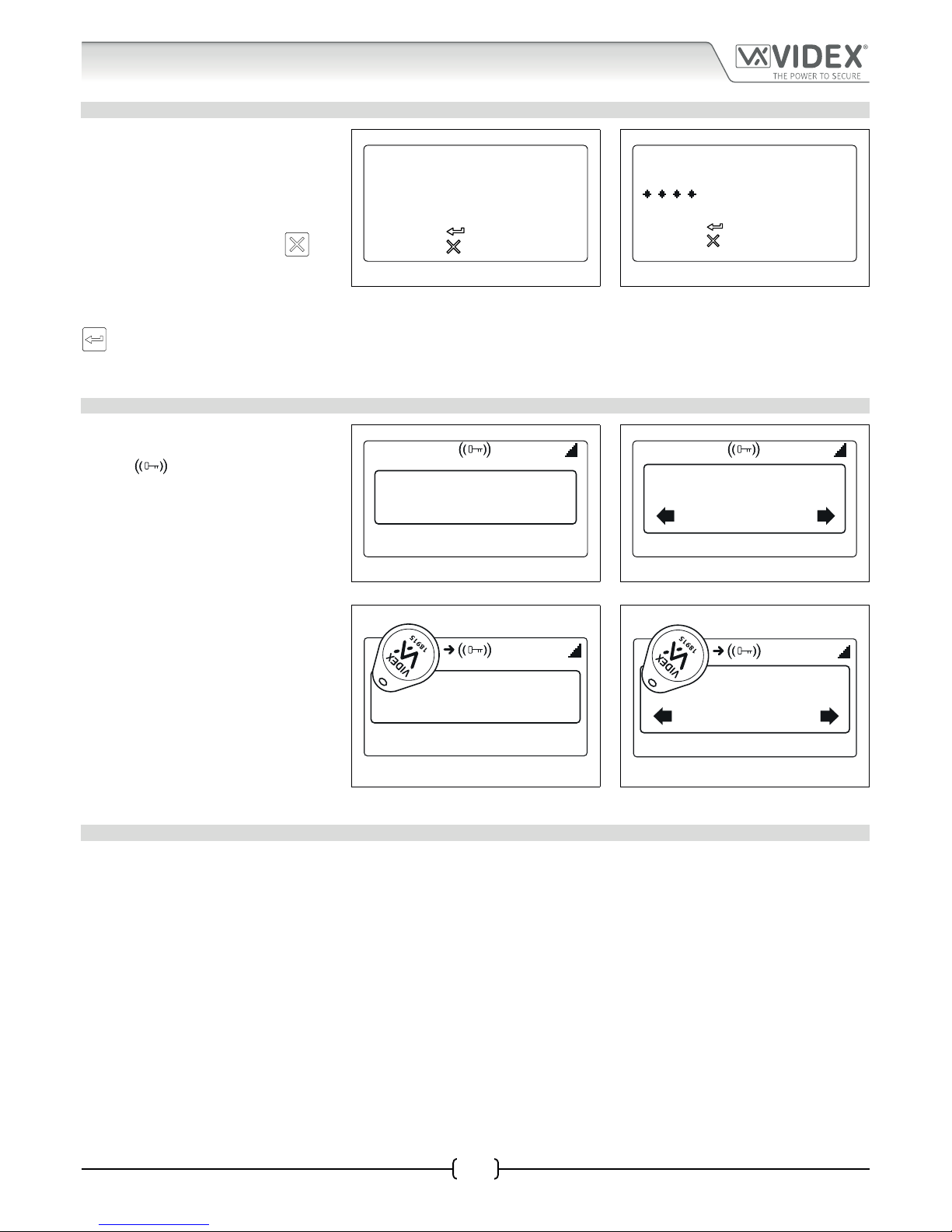
66251750-EN - V1.0 - 05/06/17
62
4000 Series Vandal Resistant Digital GSM - Technical Manual
4000 Series Vandal Resistant Digital GSM Audio Intercom with Proximity
System Operation
ENTERING A DOOR/GATE AND TRADE ACCESS CODE
If an access code is programmed into the
GSM intercom rst press the ‘0’ button,
the ‘ENTER A CODE’ screen will appear on
the display, see Fig.109. The access code
can be entered using the alpha-numeric
keypad. If an incorrect digit has been
entered press the CLEAR button
(to
delete the most recent digit entered).
Re-enter the correct digit again and so
on until the correct access code has been
entered followed by the ENTER button
, see Fig.110. The GSM intercom will
operate the onboard relay to trigger the
door/gate, also see Fig.107 and Fig.108.
Fig. 109 Fig. 110
Entering a Trade Code
If a trade code is programmed into the panel (this will require the use of the Art. 701T
timeclock set in timeclock mode and connected into the TRD terminal) follow the
same steps as if entering a door/gate code. It is important to note that the panel’s
trade facility is not related to the timeband feature.
USING THE PROXIMITY READER
If the proximity reader facility is being
used this can be conrmed if the key
symbol
is shown at the top of
the LCD graphical display, see Fig.111
and Fig.112. The user can present the
programmed fob/card in front of this
symbol to operate the door/gate, see
Fig.113 and Fig.114.
It should be noted that even if a proximity
fob/card is programmed into the digital
GSM intercom, if the proximity facility is
not enabled then the fob/card will not
operate the door/gate.
Fig. 111 Fig. 112
Fig. 113 Fig. 114
Additional user operations can be carried out via text messaging following user command table 2 on page 63.
RELEASING THE DOOR/GATE BY DIALLING THE DIGITAL GSM INTERCOM DIAL TO OPEN DTO
This feature is only possible if the dial to open, DTO, feature has been enabled on the digital GSM intercom (refer to notes on page
37). When this feature is enabled the primary number and the 3 divert numbers will be set as dial to open numbers. A call from
any of these stored numbers to the digital GSM will result in the panel dropping the call and then opening the door/gate for the
programmed time.
ENTER A CODE
to confirm
to cancel
ENTER A CODE
to confirm
to cancel
18/11/16 08:35
Enter Number
18/11/16 08:35
Or Search
Enter Number
18/11/16 08:35
Enter Number
18/11/16 08:35
Or Search
Enter Number
Page 63

66251750-EN - V1.0 - 05/06/17
63
4000 Series Vandal Resistant Digital GSM - Technical Manual
4000 Series Vandal Resistant Digital GSM Audio Intercom with Proximity
User Commands
USER COMMAND TABLES
The rst user table shows the user commands that can be carried out during a call. Successful commands are signalled by two beeps
from the telephone, errors are signalled by four beeps.
IMPORTANT NOTE: When the ED# function has been enabled the user must press the # button on their phone before pressing
any of the following user commands (also refer to page 56 for further information).
Table 1
FUNCTION 1st KEY TO PRESS 2nd KEY TO PRESS
Latch the relay (unlatch by pressing 3) 10
Release the door or gate 3 n/a
Activate auxiliary output AO
1
6 n/a
Adjust door speech volume (digital GSM speaker) 4 0 - 9 (0 = lowest, 9 = highest)
Adjust phone speech volume (digital GSM mic) 7 0 - 9 (0 = lowest, 9 = highest)
Activating auxiliary output AO in this way is only possible when A1M mode has been set to mode 001 (also see notes on pages
13 and 51, ‘set auxiliary output AO mode’) and will operate for the programmed A1T time. If the AO output time has been set to
latch simply press 6 on the phone to unlatch the output again.
The second user table shows the SMS text messages that can be sent to the digital
GSM intercom while in standby (the examples shown in the table use the default 4
digit master code 1111). Successful text commands are signalled by a single beep from
the digital GSM and where the ? is used the appropriate conrmation text returned.
Unsuccessful text commands are signalled by a long beep followed by a short beep
from the digital GSM and where the ? is used the error message text returned, as
shown in Fig.115.
Fig. 115
Table 2
FUNCTION MESSAGE TO SEND
Check the signal strength 1111SIG?
Check the available balance
2
1111BAL?
Check the software version 1111VER?
Release the door/gate 1111RLY? (? optional, send if conrmation is required)
Latch the relay 1111RLA? (? optional, send if conrmation is required)
Unlatch the relay 1111RUL? (? optional, send if conrmation is required)
Activate auxiliary output AO 1111A1O? (? optional, send if conrmation is required)
Latch auxiliary output AO 1111A1L? (? optional, send if conrmation is required)
Unlatch auxiliary output AO 1111A1U? (? optional, send if conrmation is required)
Check Time band setting 1111TBAn? (where n = timeband 1 - 9)
Check Intercom Time and Date 1111CLK?
Find a Telephone number 1111FDT”yyyyyyyyyyy”? (where yyyyyyyyyyy = telephone number, minimum of 4
digits, also refer to pages 58 and 59)
Find a Fob or Card location 1111FDF”nnnnn”? (where nnnnn = 5 digit user code printed on fob/card, also refer
to page 59)
The balance can only be checked if the correct balance check string has been stored (also see SDL notes on page 53).
Page 64

66251750-EN - V1.0 - 05/06/17
64
4000 Series Vandal Resistant Digital GSM - Technical Manual
4000 Series Vandal Resistant Digital GSM Audio Intercom with Proximity
Additional User Information
UNDERSTANDING THE SIGNAL STRENGTH SIG
When a request for signal strength message is sent to the digital GSM intercom it will reply with a 4 digit code. The code is broken
down into two parts, a signal strength code which will be between 0 – 31 or 99. Ideally the signal strength should be as close to 31 as
possible. The lower the number, the weaker the signal. Signal strengths lower than 10 may cause operational problems such as loss
of speech quality (and possibly missing DTMF tones) and network loss. A signal strength of 99 indicates it could not be detected.
The second part of the code is the BER (bit error rate). Ideally the BER code should be as close to 0 as possible, the lower the BER the
better. The example below shows the reply to expect from the digital GSM:
SIGNAL = 31
BER = 0
OK VIDEX GSM
DIALLING INTO THE DIGITAL GSM FROM ANOTHER TELEPHONE
There are three possible outcomes to dialling into the digital GSM intercom depending on the telephone number you are dialling
in from and the features setup during programming. The three possible outcomes are shown in the priority function table below
and are shown in order of priority. For example, if the number is programmed to automatically activate the relay (DTO), this will take
priority over the following two options and if the telephone number is stored as a telephone number called from one of the push
buttons, this will take priority over the last option.
Priority Function Table
FUNCTION REQUIREMENT PRIORITY
Dial in to open the Door (DTO).
After dialling the GSM number, the relay will activate
and the call will be dropped.
The telephone number of the telephone dialling
in must be stored as a primary number or one of
the divert numbers:
STNn
STDn
STEn
STFn
where n = apartment no. (500 max.) The DTO
feature must also be enabled (switched ON), refer
to page 37 for DTO set up.
1st
Dial in to activate a call (live speech, activate relay/
auxiliary AO).
After dialling the GSM number, the call will be
answered and two beeps will be heard. The speech will
then be live.
The telephone number of the telephone dialling
in must be stored as a primary number or one of
the divert numbers:
STNn
STDn
STEn
STFn
where n = apartment no. (500 max.) The DTO
feature must also be disabled (switched OFF), refer
to page 37 for DTO set up.
2nd
Dial in to open the speech from a telephone number
not stored in the digital GSM.
After dialling the GSM number, the call will be answered
and two beeps will be heard. You will then be required
to enter the 4 digit code to open the speech.
If neither of the two requirements above are met.
3rd
UNDERSTANDING THE BEEPS
Functions and errors are indicated by beeps from the digital GSM panel. The following will help you understand the dierent beeps
heard and what, if anything, needs to be done in response to the beeps.
BEEP REASON SOLUTION
Short beeps at 1 second
intervals.
Relay or auxiliary output activated. None, this is normal.
Single short beep while
the system is in standby
and not being used.
A valid text message has been received and
processed.
None, this is normal.
Page 65

66251750-EN - V1.0 - 05/06/17
65
4000 Series Vandal Resistant Digital GSM - Technical Manual
4000 Series Vandal Resistant Digital GSM Audio Intercom with Proximity
Two short beeps followed
by a long beep.
During this time the GSM
display will indicate that
it is attempting to call an
apartment, see Fig.104
on page 61.
Call made to a stored apartment number but no
actual telephone number stored.
Program a telephone number for the apartment.
Long beep, followed by
a short beep while the
system is in standby.
During this time the
GSM will send an error
message to the sender,
see Fig.115 on page 63.
Invalid text message received. If this has happened when sending one of the
programming text messages then check the message
for errors. These beeps will also be heard if the 4 digit
master code in the text message is incorrect. If you
are unsure of the 4 digit code, try resetting it to 1111.
Short beep while the
system is in use.
Manually ending a call by pressing the CLEAR
button
.
None, this conrms the call has been cancelled.
Another call can be placed if required.
Single short beep approx.
every 50 seconds after
power up. During this
time the GSM display
will indicate that it is
attempting to register
with the network, see
Fig.27 and Fig.28 on
page 20.
Not registered with a network provider but still
trying. Unable to see the SIM card or unable to
see the antenna or Other unknown registering
problem.
Leave it a short while to see if it manages to nd
the network. If the beeps repeat every 50 seconds
or so then try the following: check the SIM card
is tted correctly. Try removing the SIM card,
cleaning and tting again. Try moving the antenna
to a better location. Try changing the SIM card to
another network provider or try changing the
antenna.
PROXIMITY READER
BEEP REASON SOLUTION
Successive short beeps
lasting for the duration of
the relay time (“the door
is open”).
Programmed fob/card presented to the onboard
reader.
None, this is normal.
Single long beep (“invalid
code”).
Fob/card presented to the onboard reader that is
not programmed.
The fob/card requires programming into the GSM
PRO module (ensuring the onboard reader is
enabled).
No beeps. The onboard
reader is unresponsive.
The onboard reader has not been enabled
(regardless of whether fobs have or have not
been programmed).
Enable the onboard proximity reader.
Additional User Information
Page 66
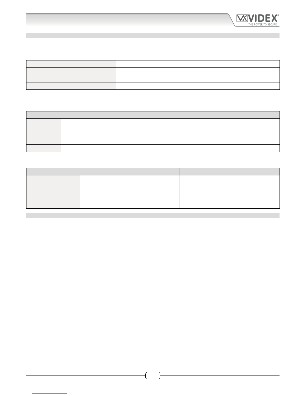
66251750-EN - V1.0 - 05/06/17
66
4000 Series Vandal Resistant Digital GSM - Technical Manual
4000 Series Vandal Resistant Digital GSM Audio Intercom with Proximity
User Management
RECORD SHEET
In order to manage the digital GSM intercom eectively it is recommended that an up to date record sheet is kept for all the
programming particularly if there is a high volume of telephone numbers and fob/cards stored in the GSM intercom. This will also be
useful if any future changes need to be made. The following table format can be used to record the digital GSM’s basic information.
Digital GSM intercom telephone No.
IMEI number
Master code (default 1111)
Master telephone No.
It is recommended that the table format below be used to record the apartment’s details from memory location 0 up to 499, which
includes the following information: the primary number (TEL) and three divert numbers (DIV1, DIV2 and DIV3), the apartment
number, username, access code, if the dial to open feature is enabled and a timeband number.
MEM. Location TEL DIV1 DIV2 DIV3 Apt. No. Username Access Code DTO enabled? Timeband (1 - 9)
0
ª ªªªª ª ª ª ª ª
499
If the onboard proximity reader is being used it is recommended that the table format below be used to record the proximity fob/
card details from memory location 0 up to 1999, which includes the following information: the site code, user code and username.
MEM. Location Site Code User Code Username
0
ªªª ª
1999
USING THE GSMSK PC SOFTWARE TO MANAGE USER INFORMATION
Because of the high volume of user information that may need to be recorded it is possible to use the GSMSK PC software (version
3.1.0.7 or later) to record and save the apartment information as an excel spreadsheet using the ‘Export Calls to Excel’ feature. The
same PC software can also be used to record and save the proximity information as an excel spreadsheet using the ‘Export Prox to
Excel’ feature.
Further information on how to do this can be found in the following technical manual:
• GSMSK-PC-SOFTWARE-MANUAL-ENUK-V1-2 (or later version).
Page 67

66251750-EN - V1.0 - 05/06/17
67
4000 Series Vandal Resistant Digital GSM - Technical Manual
4000 Series Vandal Resistant Digital GSM Audio Intercom with Proximity
Troubleshooting
SYSTEM CHECKS AND TESTING
The following table can be used to help diagnose any potential issues that may occur during installation and the system checks that
can be carried out to help resolve them.
SYMPTOM TEST
Interference on the speech. Check the signal strength 1111SIG? (if the signal strength is too low the GSM module increases
it’s power to compensate, causing interference with the speech circuits). Try relocating the
antenna or using a more powerful or directional antenna (e.g. high gain antenna).
Ensure the antenna cables are not running close to the power supply cables or the microphone
wires inside the intercom panel.
Try a dierent SIM card from a dierent network service provider as they may have better
coverage in that area.
Nothing is shown on the graphical
display and it is not illuminated.
Check the power supply has adequate voltage as described earlier in this manual (refer to
pages 9 and 18).
Try a full reset (refer to page 21)
The digital GSM module may have a fault.
The digital GSM intercom does not
respond to SMS messages.
Check the SIM card has an SMS service centre number stored. This will require putting the
SIM card into a mobile phone to check. Contact the SIM card provider if you are not sure.
Check the number you are sending the message to is correct (the number of the SIM card in
the digital GSM intercom panel).
After sending an SMS message to the digital GSM listen for a single short beep from the
intercom panel. This will indicate that the message was received and understood. If a long
beep is heard it indicates the message was either not understood or the 4 digit master code
was incorrect.
Try resetting the 4 digit master code to 1111 (refer to page 21).
The call keeps dropping out. Increase the call time (SPT) of the digital GSM intercom (refer to the programming owchart
on page 34 to program via the keypad and page 51 to program by SMS message).
Check the signal strength and if necessary, move or change the antenna or try a dierent
SIM card provider.
Speech echoes and feeds back. Try adjusting the mic and speaker volume via the keypad selecting the general settings
menu on the digital GSM intercom (refer to the programming owchart page 31).
Try adjusting the mic and speaker volume using the programmable settings during a call
(refer to user command table 1 on page 63).
Check the microphone is tted correctly in the intercom panel and that the mic hole is not
blocked in any way.
ERROR message returned in SMS
when programming or no SMS
returned at all even though a ? was
included at the end of the message
sent.
Check over the message sent again and compare it with the examples in this manual.
Common errors include:
1. Using two apostrophe marks side by side instead of “. Note that these look the
same in the message. An easy way to see if this is the problem is to move the cursor
along in the message and if the cursor can get between the two “ then it is not the
correct character used.
2. Lower case letters instead of upper case. For example using stn when STN should be used.
Page 68

66251750-EN - V1.0 - 05/06/17
68
4000 Series Vandal Resistant Digital GSM - Technical Manual
4000 Series Vandal Resistant Digital GSM Audio Intercom with Proximity
Troubleshooting
Unable to open the gate/door
from the telephone during a call
(DTMF tones not being recognised)
continued.
If the DTMF tones are not working reliably then try the following adjustments:
1. Send the following SMS command 1111AT1”AT#DTMFCFG=8,2500,1500”? to the
digital GSM and wait for a reply.
2. After receiving the reply send the SMS command 1111RBT then wait for the digital
GSM to reboot.
3. After the GSM intercom has rebooted test the door opening feature from the
telephone during a call.
If the rst solution still does not resolve the issue then try the following:
1. Send the following SMS command 1111AT1”AT#DTMFCFG=7,2300,1300”? to the
digital GSM and wait for a reply.
2. After receiving the reply send the SMS command 1111RBT then wait for the digital
GSM to reboot.
3. After the GSM intercom has rebooted test the door opening feature from the
telephone during a call.
If none of the solutions above resolve the problem then please contact Videx technical on
tel: 0191 224 3174 for further assistance. For overseas customers contact Videx customer
support on tel: (+39) 0734 631 699 for further assistance.
Page 69
66251750-EN - V1.0 - 05/06/17
69
4000 Series Vandal Resistant Digital GSM - Technical Manual
4000 Series Vandal Resistant Digital GSM Audio Intercom with Proximity
General Information
SOFTWARE REVISION
DATE SOFTWARE VERSION REVISION
02/01/17 DG4.0.0 Launch of the digital GSM (4812, 4812R).
15/05/17 DG4.0.1 Update AT command to include DTMF adjustment feature.
FURTHER READING
Additional programming information using the GSMSK PC software can be found in the following technical manual:
• GSMSK-PC-SOFTWARE-MANUAL-ENUK-V1-2 (or later version)
Additional information regarding connection to mains supply voltage can be found in the following regulations for UK based
customers:
• I.E.E. Wiring Regulations BS7671
For overseas customers please consult the relevant standards of your country.
Page 70

66251750-EN - V1.0 - 05/06/17
70
4000 Series Vandal Resistant Digital GSM - Technical Manual
4000 Series Vandal Resistant Digital GSM Audio Intercom with Proximity
Notes
Page 71
66251750-EN - V1.0 - 05/06/17
71
4000 Series Vandal Resistant Digital GSM - Technical Manual
4000 Series Vandal Resistant Digital GSM Audio Intercom with Proximity
Notes
Page 72
THE POWER TO SECURE
The product is CE marked demonstrating its conformity and is for distribution
within all member states of the EU with no restrictions. This product follows
the provisions of the European Directives 2014/30/EU (EMC); 2014/35/EU
(LVD); 2011/65/EU (RoHS): CE marking 93/68/ECC.
Main UK oce:
VIDEX SECURITY LTD
1 Osprey Trinity Park
Trinity Way
LONDON E4 8TD
Phone: (+44) 0870 300 1240
Fax: (+44) 020 8523 5825
www.videxuk.com
marketing@videxuk.com
Northern UK oce:
VIDEX SECURITY LTD
Unit 4-7
Chillingham Industrial Estate
Chapman Street
NEWCASTLE UPON TYNE - NE6 2XX
Tech Line: (+44) 0191 224 3174
Phone: (+44) 0870 300 1240
Fax: (+44) 0191 224 1559
Greece oce:
VIDEX HELLAS Electronics
48 Filolaou Str.
11633 ATHENS
Phone: (+30) 210 7521028
(+30) 210 7521998
Fax: (+30) 210 7560712
www.videx.gr
videx@videx.gr
Danish oce:
VIDEX DANMARK
Hammershusgade 15
DK-2100 COPENHAGEN
Phone: (+45) 39 29 80 00
Fax: (+45) 39 27 77 75
www.videx.dk
videx@videx.dk
VIDEX ELECTRONICS S.P.A.
Via del Lavoro, 1 - 63846 Monte Giberto (FM) Italy
Tel (+39) 0734 631669 - Fax (+39) 0734 632475
www.videx.it - info@videx.it
Benelux oce:
VIDEX BENELUX
E3 Iaan, 93
B-9800 DEINZE
Phone: (+32) 9 380 40 20
Fax: (+32) 9 380 40 25
www.videx.be
info@videx.be
Dutch oce:
NESTOR COMPANY BV
Business Centre Twente (BCT )
Grotestraat, 64
NL-7622 GM Borne
www.videxintercom.nl
info@videxintercom.nl
All Countries:
VIDEX ELECTRONICS S.P.A.
www.videx.it - technical@videx.it
Tel (+39) 0734 631669 - Fax (+39) 0734 632475
UK Customers:
VIDEX SECURITY LTD
www.videxuk.com - tech@videxuk.com
Tech Line: 0191 224 3174 - Fax: 0191 224 1559
MANUFACTURER CUSTOMER SUPPORT
 Loading...