

Page 1
4KX Series Audiokit
Vproxphone Kit 4KX Audiokit with proximity reader
Art.4KX - Installation instructions
1
66250582-EN - V2.2 - 01/06/16
Page 2
4KX Series Audiokit
Vproxphone Kit 4KX Audiokit with proximity reader
Art.4KX - Installation instructions
2
66250582-EN - V2.2 - 01/06/16
Page 3
4KX Series Audiokit
Wiring Guide Line
All intercoms wiring must run separately from the mains cable.
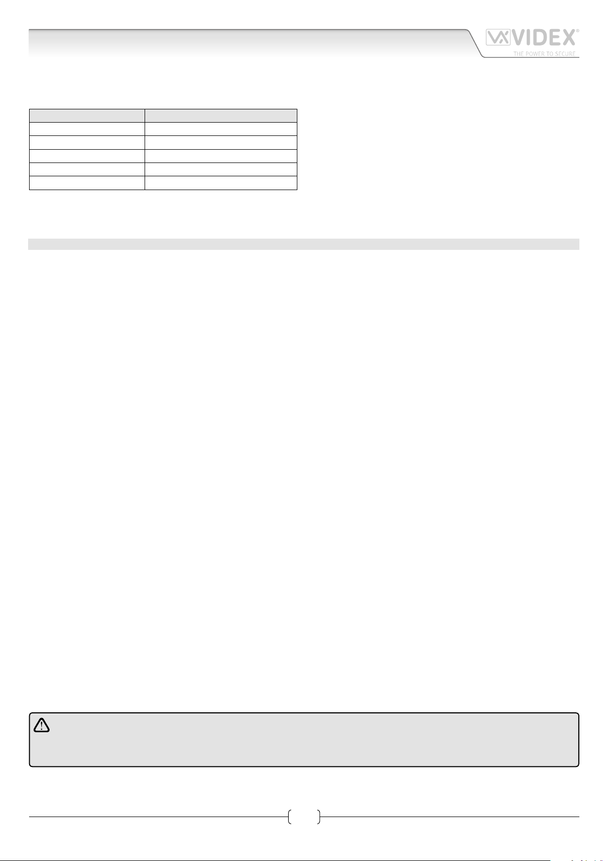
The cable type should be CW1308 or an equivalent cable. The cable size should comply with the table below.
DISTANCE METERS CABLE SIZE MM2
50 0.35
100 0.5
200 0.75
300 1.0
400 1.5
Max resistance of all lines: 8 Ohm
Before powering the system up, the wiring should be double checked to ensure it complies with the wiring diagram supplied.
TROUBLE SHOOTING GUIDE
In the event of the system not functioning correctly when you power up, the following points can be checked (a multimeter will be
needed).
SYSTEM DEAD
• Check mains input to the transformer.
• Check the 12Vdc (+12 terminal) output from the power supply.
• Check fuses.
• Check for shorts on power supply wires.
SPEECH & LOCK WORKS BUT NO ELECTRONIC CALL TONE
• Check the link between “C” and “C1” terminals of the speaker unit.
• Call wire to terminal “4” of the handset broken on in short circuit; check the walk of the call wire.
NO SPEECH FROM THE DOOR PANEL
• Check and/or adjust the volume operating on trimmers controls on rear of speaker unit.
• Check the wire from terminal “2” of the speaker unit to terminal “2” of the handset.
NO SPEECH FROM THE HANDSET
• Check and/or adjust the volume operating on trimmers controls on rear of speaker unit.
• Check the wire from terminal “1” of the speaker unit to terminal “1” of the handset.
LOCK DOES NOT WORK
• Check on the handset the link between terminals “1” and “5”.
• Check the 13Vac output on the transformer.
• Check the wires of the electric lock.
• Wires section not in conformity with the table above.
FEEDBACK PROBLEM LARSEN EFFECT
• Check that the handset microphone is rmly tted inside its housing.
• Check that the speaker unit microphone is rmly tted inside its housing and nothing is obstructing the microphone hole.
• Adjust the volume operating on trimmer controls on rear of the speaker unit.
HUM ON THE SPEECH LINES
• Check that system cables are not running close to any high voltage or mains cables.
• Check that the system is wired exactly as shown on the wiring diagram.
WE RECOMMEND THIS EQUIPMENT IS INSTALLED BY A COMPETENT ELECTRICIAN, SECURITY OR COMMUNICA
TIONS ENGINEER.
If further assistance is required, call the technical help desk on 0191-2243174 for uk customers or +39 0734631669
for other countries.
3
Art.4KX - Installation instructions
66250582-EN - V2.2 - 01/06/16
Page 4

4KX Series Audiokit
4000 Series Surface and ush mounting door station installation
EXAMPLE: INSTALLING A FOUR MODULE OUTDOOR STATION
B
C
g. 1
Y
H
G
F
G
g. 4 g. 5 g. 6 g. 7
C
A
E
D
g. 2
W
C
H
C
D
C
M
g. 3
L
L
H
M
N
g. 10
g. 14
P
g. 11
M
g. 8
H
Q
H
g. 9
N
g. 12
P O
N
g. 13
g. 15
Art.4KX - Installation instructions
g. 16
g. 17
g. 18
4
66250582-EN - V2.2 - 01/06/16
Page 5

4KX Series Audiokit
4000 Series Surface and ush mounting door station installation
INSTALLING A SURFACE MOUNT DOOR STATION
1. Place the surface box against the wall (165-170cm between the top of the box and the oor level as shown in Fig.1) and mark the
xing holes for the wall plugs and the hole for the cables E (g.2). Observe the orientation of the box with the hinge on the left;
In order to prevent water ingress we highly recommend using a silicon sealant between the wall and the back box C
(Fig.3) and around all holes D (Fig.3);
2. As shown on Fig.2, drill the xing holes A, insert the wall plugs B and feed the cables E through the surface box opening D, x
surface box C to the wall using the screws F;
3. Apply the Y silicon sealant on top of each module as shown in Fig.4;
4. Before installation of the module support frame, hook the modules G to the support frame H as shown in Fig.5 then, as shown
in Fig. 6, t the two anti-tampering locks W for each module (do the same for the second module support frame);
5. When you have more than one support frame, hook the support frame to the surface box starting from the left. For convenience we
will described how to attach the left frame but the same must be carried out for the right frame. As shown in Fig. 7, hook the module
support frame H (complete with modules) to the surface box C moving the frame as suggested from pointers. Ensure that the pivots
L (Fig. 7) go inside the relevant housing M as shown in Fig. 8;
6. As shown on Fig. 9, pull back the module support frame H while moving it slightly to the left as suggested by the pointers;
7. As shown in Fig. 10, open the module support frame H as suggested by the pointer, hook the hinge locks N to the hinges M,
make the required connections using the screwdriver provided P (at blade end) and make the required adjustment by adjusting the settings (through openings O) and adjust trimmers;
8. Repeat the same operations described above for the second module support frame (or for the third if available);
9. When the system has been tested and is working correctly, move back the module support frames carefully, x them to the surface
box using the screwdriver provided P (torx end) and the pin machine torx screws Q (Fig. 11). Note: do not over tighten the screws
more than is necessary.
INSTALLING A FLUSH MOUNTING DOOR STATION
When ush mounting and the number of modules is greater than 3, the required back boxes need to be linked together (before
embedding them in the wall) as shown on Fig. 14, 15 and 16:
• Arrange the back boxes and remove knockouts to allow cables to be fed from one back box to the other;
• Hook the spacers to rst back box then hook the second back box to obtain the result shown on Fig. 16;
1. Protect the module support frame xing holes from dust then embed the back box into the wall (165-170cm between the top
of the box and the oor level as shown on the Fig. 1) feeding the cables E (Fig. 2) through a previously opened hole in the box.
Observe the direction of the box ensuring the hinge is on the left and take care that the box prole is in line with the nished
wall prole;
In order to prevent water ingress we highly recommend using a silicon sealant between the wall and the back box H
(Fig.12);
2. Continue from step 4 of surface mounting instructions , but at step 7 hook the hinge locks N as shown on Fig. 13.
Note: if additional holes are made in the surface box, oxidation problems may appear unless the unprotected metal is
coated with a protective paint.
NOTES
• The screwdriver’s blade has two sides, one at and one torx, to select one of them unplug the blade from the screwdriver body
and plug it into the required side.
• The example shows the use of only one back box bottom hole for wires, this is done to keep le drawings clear. Naturally the
installer can use the left hole or the right or both if required.
HOW TO REMOVE THE CARD NAME HOLDER
• To avoid damage to the module front plate, tape the side that will be in contact with the screwdriver blade;
• lnsert the screwdriver (at side) into the card-holder hole as shown in Fig. 17;
• Move the screwdriver to the left as shown in Fig. 18 to extract the card name holder;
• Edit the card name then replace it inside the holder and ret: insert the holder inside its housing from the left or right side then
push the other side until it clips into place.
Art.4KX - Installation instructions
5
66250582-EN - V2.2 - 01/06/16
Page 6

4KX Series Audiokit
Note
Art.4KX - Installation instructions
6
66250582-EN - V2.2 - 01/06/16
Page 7

4KX Series Audiokit
Note
Art.4KX - Installation instructions
7
66250582-EN - V2.2 - 01/06/16
Page 8

MANUFACTURER
The product is CE marked demonstrating its conformity and is for distribution
VIDEX ELECTRONICS S.P.A.
Via del Lavoro, 1 - 63846 Monte Giberto (FM) Italy
Tel (+39) 0734 631669 - Fax (+39) 0734 632475
www.videx.it - info@videx.it
CUSTOMER SUPPORT
All Countries:
VIDEX ELECTRONICS S.P.A.
www.videx.it - technical@videx.it
Tel: +39 0734-631669 - Fax: +39 0734-632475
UK Customers:
VIDEX SECURITY LTD
www.videx-security.com
Tech Line: 0191 224 3174 - Fax: 0191 224 1559
Main UK oce:
VIDEX SECURITY LTD
1 Osprey Trinity Park
Trinity Way
LONDON E4 8TD
Phone: (+44) 0870 300 1240
Fax: (+44) 020 8523 5825
www.videx-security.com
marketing@videx-security.com
Greece oce:
VIDEX HELLAS Electronics
48 Filolaou Str.
11633 ATHENS
Phone: (+30) 210 7521028
(+30) 210 7521998
Fax: (+30) 210 7560712
www.videx.gr
videx@videx.gr
Northern UK oce:
VIDEX SECURITY LTD
Unit 4-7
Chillingham Industrial Estate
Chapman Street
NEWCASTLE UPON TYNE - NE6 2XX
Tech Line: (+44) 0191 224 3174
Phone: (+44) 0870 300 1240
Fax: (+44) 0191 224 1559
Danish oce:
VIDEX DANMARK
Hammershusgade 15
DK-2100 COPENHAGEN
Phone: (+45) 39 29 80 00
Fax: (+45) 39 27 77 75
www.videx.dk
videx@videx.dk
Benelux oce:
VIDEX BENELUX
E3 Iaan, 93
B-9800 DEINZE
Phone: (+32) 9 380 40 20
Fax: (+32) 9 380 40 25
www.videxbenelux.be
info@videxbenelux.be
within all member states of the EU with no restrictions. This product follows
the provisions of the European Directives 2014/30/EU (EMC); 2014/35/EU
(LVD); 2011/65/EU (RoHS): CE marking 93/68/EEC.
 Loading...