

Page 1
VK6N
SERIES VIDEOKITS
VIDEOKIT SERIE
One Way and Two Way
Monofamiliari e Bifamiliari
VK6N
Norme Tecniche
Owner’s Manual
Factory - Office
VIDEX ELECTRONICS S.p.A. Via del lavoro,1 63020 MONTEGIBERTO (AP) - ITALY
Phone: (+39) 0734 - 631669 Fax: (+39) 0734 - 632475 www.videx.it e-mail: info@videx.it
Main UK office
VIDEX SECURITY LTD
1 Osprey
Trinity Park Trinity Way
London E4 8TD
Phone: (+44) 0870 - 3001240
Fax: (+44) 0208 - 5235825
www.videx-security.com
e-mail: info@videx-security.com
Northern UK office
VIDEX SECURITY LTD
Unit 5-7
Chillingam Industrial Estate
Chapman Street
NEWCASTLE UPON TYNE NE6 2XX
Phone:(+44) 0870-3001240
Tech-line:(+44) 0191-2243174
Fax:(+44) 0191 224 1559
Greece office
VIDEX HELLAS Electronics
48 Filolaou Str.
11633 Athens
Phone: +30 210 - 7521028/7521998
Fax: +30 210 - 7260712
www.videx.gr
e-mail: videx@videx.gr
We recommend
This equipment is installed by a
Competent Electrician, Security or
Communications Engineer
Danish office
VIDEX DANMARK
Hammershusgade 15
DK - 2100 Copenhagen
Phone: +45 39 29 80 00
Fax: +45 39 27 77 75
www.videx.dk
Page 2
La marcatura CE di conformità indica che ilprodotto soddisfa irequisiti delle
Direttive dellaComunità EconomicaEuropea in vigore (in particolare quelle
73/23/CEE e 93/68/CEE e Compatibilità elettromagnetica 89/336) ad esso
applicabili.
La marcatura CE, apposta sui prodotti dal fabbricante (o da un suo
mandatario) sotto la propria responsabilità, è stata creata con l'intento di
eliminare gli ostacoli alla circolazione dei prodotti all'interno degli Stati
membri dell'Unione Europea armonizzando diverse normative a carattere
nazionale.
MARKINGMARCATURA
CE conformity marking indicates that the product respects the requirements
of the applicable European Community Directives in force (specifically
73/23/EEC, 93/68/EEC and the Electromagnetic Compatibility Directive
89/336).
CE marking is applied by the manufacturer (or party delegated to do so by
the manufacturer) under their own responsibility. It was created to eliminate
obstacles to the circulation of products in European Union Member States
by harmonising different nationalstandards.
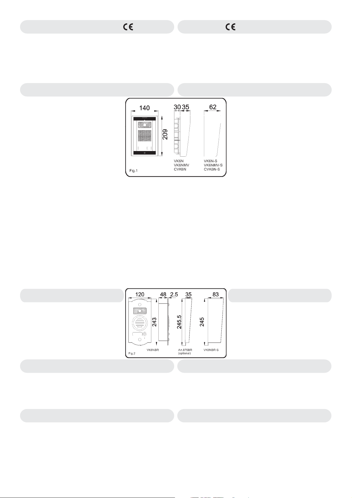
VK6N VK6N-S
Il VIDEOKIT VK6N è un sistema videocitofonico studiato per una facile
installazione. Non necessita di cavo coassiale per la trasmissione del segnale
video edè dotato diuna circuiteria di grande affidabilità. Ilposto esterno video,di
ridotte dimensioni, è disponibile sia in versione con montaggio da incasso
(VK6N) che inquella con montaggio da superficie (VK6N-S).Tutti i videokit sono
disponibili anche in versione bifamiliare ( ) VK6N-2, VK6N-2S, CVK6N-2,
VK6NMV-2 ecc. Sono disponibili diverse varianti del kit in base alla placca
frontale del posto esterno, chenella versionestandard è in acciaio inossidabile :
VK6N/A - VK6N/A-S
VK6N/W - VK6N/W-S
VK6N/B - VK6N/B-S
VK6N/BZ- VK6N/BZ-S
L’Art. (kit con posto esterno daincasso) ècomposto da :
VK6N
Nr.1 Art.831K
-
di alta qualità, diodiled per illuminazione all’infrarosso,amplificatore audio ed
1 pulsante di chiamata. E’ completa di scatola da incasso (185x115x30 mm),
sostegno con cerniera in acciaioe tettuccioanti-pioggia (209x140x35 mm).
Nr.1 Art.3351
-
Nr.1 Art.850K
-
primario: 127 e 230Vac,sec.24Vac, 1,6A;
Norme tecniche;
Nr.1
-
Art.VK6N-2:
installazione bifamiliare: 2Videocitofoni,2Trasformatori ed ilposto esterno con 2
pulsanti di chiamata (Art.831K-2).
Art.VK6N-S:
muro del posto esterno video(dimens.209x140x62 mm).
Art.VK6N-2S: ComeArt.VK6N-2macon posto esterno da superficie.
Come Art.VK6N ma con i componenti necessari per una
Come Art.VK6N macon scatola di protezione permontaggio a filo
posto esterno video in alluminioanodizzato argento.
posto esterno video in alluminioverniciato bianco.
posto esterno video in alluminioverniciato marrone.
posto esterno video in alluminioanodizzato bronzo.
- Modulo unità di ripresa che incorpora: una telecamera CCD
- Videocitofono con schermo 4” piatto.
- Trasformatore di alimentazione in barra DIN 5 moduli;
VIDEOKIT
-2
VK6N VK6N-S
The VK6N VIDEOKIT is an easy to install videointercom system. It does not
require coaxial cable for the video signal and it is equipped with the latest
electronic components to guarantee high quality and reliability. The video
outdoor station provided with the kit is a small size, can be flush (VK6N) or
surface mounted (VK6N-S) and the standard version has a stainless steel front
plate. All kits are availablein two button version ( ) (for flush mount)and
VK6N-2S
There are many kit versions available depending on the door panel finish
required:
VK6N/A - VK6N/A-S
VK6N/W - VK6N/W-S
VK6N/B - VK6N/B-S
VK6N/BZ- VK6N/BZ-S
Art.VK6
-
-
-
-
Art.VK6N-2:
outdoor station with 2 callpush buttons (Art.831K-2).
Art.VK6-S:
(209x140x62 mm).
Art.VK6-2S:
box (209x140x62 mm).
(for surface mount).
video outdoor station in aluminium.
video outdoor station in whitefinish.
video outdoor station in brownfinish.
( with flushing outdoor station)is composed by:
Nr.1 Art.831K
leds for infrared illumination, audio amplifiers and one call button. Complete
with flush mounting box (185x115x30 mm), module support with hinge and
rainshield (209x140x35 mm).
Nr.1 Art.3351
Nr.1 Art.850K
230 V a.c., secondary 24 V a.c.; power 24VAmax.
Nr.1
- Technical specifications.
As Art.VK6N but with 2 videophones, 2 power transformer and
As Art.VK6N but with surface mounting outdoor station using box
As Art.VK6N-2 but with surface mounting outdoor station using
video outdoor station in bronzefinish.
- Outdoor station.Itincorporates a high qualityCCDcamera,
- Videophone with a 4” flat screen monitor.
- Power transformer in 5 module DIN box; primary: 127 and
VIDEOKIT
-2 VK6N-2
VK6NBR VK6NBR-S
VIDEOKIT con P.E. in ottone
Come il Kit ma con posto esterno in
ottone. Le dimensioni e gli ingombri del posto
esterno sono come da figura 2.
disponibile anche in versione a colori ma solo e
sempre in versione unifamiliare.
Come il Kit ma con unitàdiripresa a colori ( ) e
videocitofono a colori . Nella versione standard il posto esterno
monta una placca in acciaio inox e sono disponibili le stesse varianti del kit
VK6N
distanza di 80cm; per migliorare la visibilità notturna illuminare
adeguatamente l’ambiente.
VK6NMV VK6NMV-S
Come il Kit ma con in dotazione il videocitofono con memoria
video ed il relativo alimentatore . L’Art.3551
memorizza, in automaticoalla ricezione di ognichiamata o manualmente su
pressione dell’apposito tasto, fino a 32 immagini con relativa data e ora.
Raggiunto il limite delle 32 immagini, la memorizzazione riparte a partire
dalla prima(vengono sostituite le immagini più vecchie). L’alimentatore
Art.850K/MV
127 o 230Vac e fornisce due tensioni in uscita 24Vac 1.6A (alimentazione
videocitofono) e 12Vdc 0,2A (alimentazione memory board).
Art.VK6N
Questo kit è
CVK6N CVK6N-S
Art.VK6N Art.831K COLOUR
Art.3451
: A,W,B e BZ. Inassenzadi luce permette una buonavisione fino alla
VIDEOKIT A COLORI
VIDEOKIT CON MEMORIA VIDEO
Art.VK6N
Art.3551 Art.850K/MV
e realizzato in contenitore DIN 8 moduli, accetta in ingresso
VK6NBR VK6NBR-S
VIDEOKIT with brass outdoor station
Art.VK6N
As but with brass outdoor station. The
outdoor-station dimensions are as shown in Figure
2. This kit is also available in colour version (One
button version only).
CVK6N CVK6N-S
Same as but with outdoor station and colour
videophone .
Outdoor station, in standard version, with front plate in stainless steel,
available also in A, W, B and BZ. In a completely dark place, it illuminates
the visitor up to a distance of 80cm. At night, a suitable illumination is
required to maintain agoodcolour image.
Art.VK6N Art.831K COLOUR
Art.3451
VK6NMV VK6NMV-S
Same as but with videophone with video memory and
relevant power supply . The Art.3551 allows the storage of 32
video images, automatically at every external call or manually by pressing
relevant push button. It also stores date and time of the occurred storage.
Over 32 images thefirststored is replaced by the newoneand so on.
The is a power supply in 8modules DIN box; primary 127 and
230 V a.c., secondary 24 V a.c. 1.6 A (Videophone power supply) and 12 V
dc 0,2 A (memory board power supply).
VK6N Art.3551
Art.850K/MV
Art.850K/MV
COLOUR VIDEOKIT
VIDEOKIT WITH MEMORY
2
Page 3
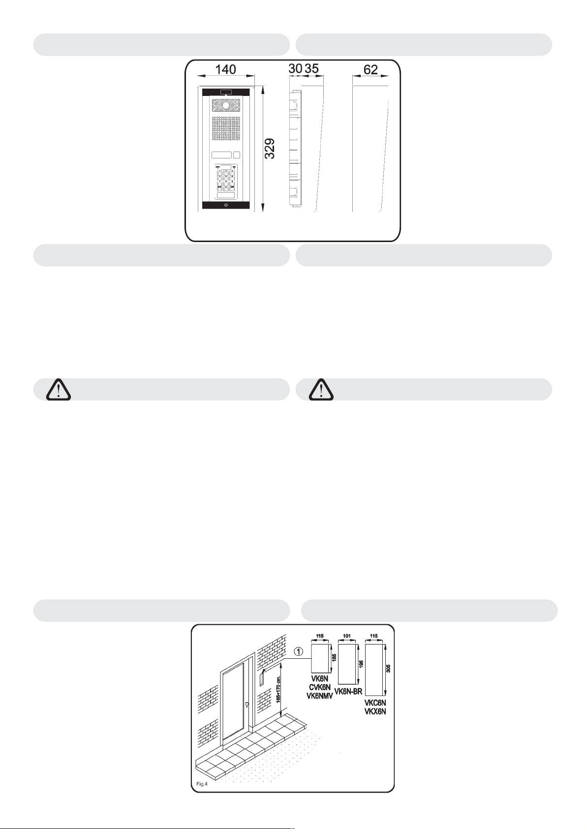
VKC6N VKC6N-S
VIDECODE VIDEOKIT CON TASTIERA DIGITALEAPRIPORTA
VKC6N VKC6N-S
VIDECODE VIDEOKIT WITH DIGITAL CODELOCK KEYPAD
Come il videokit ma con
l’aggiunta, sul posto esterno, del modulo
tastiera digitale apriporta .
La versione standard del kit prevede il
posto esterno con placca in acciaio
inossidabile ma sonodisponibili anche altre
due varianti in alluminio(/A)ebronzo (/BZ).
Montaggio da incasso: scatola da incasso
(305x115x30mm),
sostegno con cerniera in acciaio inox e
tettuccio (329x140x35mm).
Montaggio da superficie: scatola
protezione (329x140x62mm).
Valigiadimensioni45x41x10cm.
Peso totale 5 Kg.
La serratura elettrica non è compresa nei
KIT.
VKX6N VKX6N-S
Come il kit Art.VK6N, ma con l’aggiunta del sistema di controllo accessi
VproX.
Comprende gli stessi componentidelVK6Npiù:
-
Art.849 Lettore di chiavidiprossimità;
Nr.1
-
Art.VproX20 Unità di controlloper1porta e 20 chiavi diprossimità;
Nr.1
-
Art.955/C Chiavi di prossimità in formato “Card” (disponile a
Nr.3
richiesta in formato “portachiavi”Art.955/T).
Nelle versioni bifamiliaridel kit (VKX6N-2o VKX6N-2S) sono fornite6 chiavi
di prossimità formato “Card”. Come per il VK6N sono disponibili diverse
varianti delkit in base alla placcafrontale del posto esterno (/A,/W,/B, /BZ).
Le dimensioni e gliingombrisonogli stessi dei kit VKC6NeVKC6N-S.
Art.VK6N
Art.VX800-2L
Fig.3
VIDEOKIT con lettore di prossimità
COLLEGAMENTO ALLA RETE ELETTRICA ED
INSTALLAZIONE DELL’ALIMENTATORE
La realizzazione dell’impianto deveessereeseguita nel rispetto delle vigenti
normative nazionali, in particolaresiraccomandadi:
Collegare l’impianto alla rete elettrica tramite un
·
interruzione omnipolare
contatto di almeno 3mm per ciascun polo e che sia in grado di
disconnettere tutti i polisimultaneamente;
Il deve essere posizionato in un
dispositivo di interruzione omnipolare
·
luogo tale da consentirneunfacileaccesso in caso di necessità.
Installazione dell’alimentatore
Rimuovere i coperchi copri-morsetti svitando le relative viti e tirandoli
-
verso l’alto;
Fissare l’alimentatore su barra DIN o direttamente a parete utilizzando le
-
viti ed i relativitasselliadespansione forniti a corredo;
-
Togliere la tensione di rete tramite il dispositivo sopraindicato ed eseguire
le connessioni come previstodagli schemi proposti (la connessione verso
la rete va effettuata in base allatensionedisponibile127 o 230Vac).
-
Verificareche non vi siano erroridi connessione e che ifilisiano ben serrati
nei morsetti;
-
Inserire a scatto icoperchicopri-morsettie fissarli tramite le relativeviti;
-
Eseguiti tutti i collegamenti,daretensioneall’impianto.
che abbia una distanza di separazione del
dispositivo di
Same as but with the addition of
a digital code lock module .
Outdoor station in standard version, with
front plates in stainless steel, also available
in Aand BZ.
Flush mounting: back box (305x115x30
mm), module support with hinge and
rainshield (329x140x35 mm).
Surface mounting: surface mounting box
(329x140x62 mm).
Briefcase dimensions cm. 45x41x10 –
Weight 5 Kg.
The electrical lock is not included in the
KITS.
VKC6N
VKX6N
VKC6N-S
VKX6N-S
VKX6N VKX6N-S
As Art.VK6N but with the addition of the VproX proximity access control
system. It includes thesamecomponents of VK6N plus:
Art.849 Proximity Card Reader;
-
Nr.1
Art.VproX20 Control unit for1door and 20 proximity keys;
-
Nr.1
Art.955/C Proximity Cards (TagArt.955/T availableon request).
-
Nr.3
In the two way kit version (VKX6N-2 or VKX6N-2S) 6 proximity cards are
supplied. The front plate in Stainless Steel, available also in /A, /W, /B, /BZ.
The outdoor station size and protrusion are the same of the VKC6N and
VKC6N-S kits.
Art.VK6N
Art.VX800-2L
VIDEOKIT with proximity card reader
CONNECTION TO MAINS AND
POWER SUPPLY MOUNTING INSTRUCTIONS
The system must be installed according to national rules in force, in
particular we recommend to:
Connect the system to the mains through an
·
which shallhave contact separation of at least 3mmin each pole and shall
disconnect all poles simultaneously;
The shall be placed for easy access and the
·
all-pole circuit breaker
switch shall remain readilyoperable.
Power Supply Installation
Remove the terminal sidecoversbyunscrewing the retaining screws;
-
Fix the power supply to a DIN bar or directly to the wall using two
-
expansion type screws;
Switch off the mains using the circuit breaker mentioned above and then
-
make the connections asshownonthe installation diagrams;
Check the connections andsecurethewires into the terminals;
-
Replace the terminal coversandfixthem using the relevant screws;
-
When all connections aremade,restorethe mains.
-
all-pole circuit breaker
ISTRUZIONI PER IL MONTAGGIO DEL POSTO ESTERNO MOUNTING INSTRUCTIONS OF THE OUTDOOR STATION
Scegliere una posizione per il posto
esterno tale che i raggi solari o altre fonti
luminose di forte intensità, non
colpiscano direttamente l’obiettivo della
telecamera. Far eseguire i collegamenti
necessari secondo gli schemi proposti,
impiegando delle apposite
canalizzazioni separate dagli impianti
ad alto voltaggio. Per il montaggio da
incasso, si consiglia di murare la scatola
(1) all’altezza mostrata in Fig.4 (bordo
superiore della scatola da incasso a
165-170 cm da terra)
Choose the location for fixing the
outdoor station ensuring that no sunlight
or other bright light is allowed to shine
directly into the camera lens.
Make all connections following provided
diagrams; prepare ducts separate from
other electrical lines. For flush
mounting, set the back box (1) at 165170 cm from ground level as shown in
Fig.4.
3
Page 4
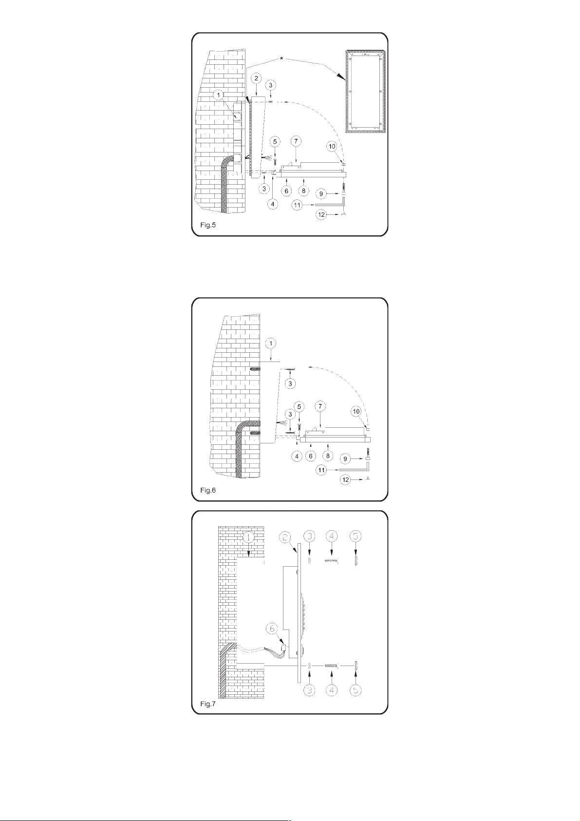
Montaggio da incasso (Fig.5)
(Art.VK6N, VK6NMV, CVK6N, VKC6N,
VKX6N)
!
Murare la scatola da incasso (1) lasciando
dal bordo superiore a terra, 165-170cm
come mostrato in figura4(pagina3).
Accertarsi che iforidi fissaggio presenti nella
!
scatola da incasso siano ben puliti (in caso
contrario provvedere alla loropulizia).
Montare sulla scatola da incasso il tettuccio
!
antipioggia (2) utilizzando le 4 viti in
dotazione (3) come mostratoinfigura5.
Inserire la cerniera (4) del gruppo “supporto
!
unità di ripresa” (8) nell’apposita sede della
scatola da incasso efissarlatramitele 2 viti in
dotazione
Passare al collaudo e test dell’impianto
!
prima di completare il montaggio del posto
esterno.
ruotare il supporto (8) verso l’alto e fissarlo
!
alla scatola daincasso,utilizzando la vite (9),
l’anello distanziale (10) e la chiave a brucola
(11). Ricoprire la sede della vite con il
coperchio in plastica (12)indotazione.
Applicare del silicone sulla superficie
posteriore del tettuccio, prima di fissarlo alla
scatola da incasso, per sigillare la scatola
contro eventuali infiltrazioni d’acqua.
(5).
*IMPORTANTE!
Flush mounting (Fig.5)
(Art.VK6N, VK6NMV, CVK6N, VKC6N,
VKX6N)
!
Flush the back box (1) into the wall at 165170 cm from groundlevel(Fig.4 Page 3).
If necessary clean and tidy the fixing holes
!
for module support andothervarious holes.
Fix the rainshield(2) by using the fourscrews
!
provided (3).
Insert the hinge (4) of the front support (8)
!
into the back box and fix it by using the two
screws provided (5).
Test the system and then complete the
!
outdoor station mounting.
Rotate the support (8) and fix it to the back
!
box with thescrew (9), the plastic spacer(10)
and the alan key provided (11). Mask the
screw by using the plastic cover (12)
provided.
Note: to avoid water infiltrations apply silicon
sealing to the back surface of the rainshield
then fix it to the back box by using the four
screws provided.
*IMPORTANT!
Montaggio a filo muro(Fig.6)
(Art.VK6N-S, VK6NMV-S, CVK6N-S,
VKC6N-S, VKX6N-S)
!
Installare a filo muro, alle quote mostrate in
(Fig.4 di Pagina 3),
(1) utilizzando le quattro viti ad espansione
(3).
!
Fissare la cerniera (4) del gruppo “supportounità di ripresa” (8, utilizzando le due viti in
dotazione (5).
!
Passare al collaudo e test dell’impianto
prima di completare il montaggio del posto
esterno.
!
Ruotare il supporto (8) verso l’alto e fissarlo
alla scatola, utilizzando la vite (9), l’anello
distanziale (10) e la chiave a brucola (11).
Ricoprire la sede della vite conil coperchio in
plastica (12) in dotazione.
la scatola di protezione
Art.VK6NBR Montaggio del posto
esterno (Fig.7)
!
Nel caso di montaggio da superficie, fissare
(alle quote di Fig.4 Pagina 3) la scatola a
muro con le 4 viti fornitea corredo edi relativi
tasselli ad espansione e procedere con i
passi successivi tenendo presente di dover
fissare la scatola da incasso (1) alla scatola
da superficie invece dimurarla.
!
Murare la scatola da incasso (1) lasciando
dal bordo superiore a terra, 165-170cm
come mostrato in figura4(pagina3).
!
Accertarsi che iforidi fissaggio presenti nella
scatola da incasso siano ben puliti (in caso
contrario provvedere alla loropulizia).
!
Collegare il connettore (6) all’unità di ripresa
(2).
!
Sostenendo l’unità di ripresa, passare al
collaudo e test dell’impianto prima di
completare il montaggio delpostoesterno.
!
Inserire ciascuna delle 2 viti in dotazione (4)
nelle relative boccole (3) e quindi negli
appositi fori dell’”unità di ripresa” (2) per
fissare quest’ultima alla scatola da incasso
(1).
!
Completare il montaggio del posto esterno
avvitando i 2 riporti “copri-boccola” ( 5) alle
2 boccole (3).
Surface mounting (Fig.6)
(Art.VK6N-S, VK6NMV-S, CVK6N-S,
VKC6N-S, VKX6N)
!
Fix surface box (1) to the wall at 165-170 cm
from ground level (Fig.4on Page 3) by using
the four expansion typescrews(3) provided.
!
Fix hinge (4) of the front support (8) using the
two screws provided (5).
!
Test the system and then complete the
outdoor station mounting.
!
Rotate the support (8) and fix it to the back
box with the screw (9), the plastic spacer (10)
and the alan key provided (11). Mask the
screw by using theplasticcover (12) provided.
Art.VK6NBR Outdoor Station
Mounting (Fig.7)
!
For surface mounting, fix surface box to the
wall at 165-170 cm from ground level (Fig.4
on Page 3) using the four expansion type
screws provided. Continue as described
below but first fix the back box (1) to the
surface box instead offlushingit into the wall.
!
Flush into the wall the back box (1) at 165170 cm from groundlevel(Fig.4 Page 3).
!
If necessary clean and tidy the fixing holes
for module support andothervarious holes.
!
Insert the connector (6) onto the front
panel(2).
!
Test the system and then complete the
outdoor station mounting.
!
Fix the front panel (2) into the back box (1) by
inserting first the 2 screw (4) into the 2
bushes (3) and then into the front panel
through the relevant holes.
!
Cover the 2 screws (4) by screwing the 2
covers (5) to the2bushes (3).
4
Page 5

B
F
B
C
N
O
N
L
E
G
E
M
I
B
D
H
A
B
E
Fig.9
E
Istruzioni di montaggio dei
Videocitofoni Art.3351,3451,3551
Applicazione a muro della piastra di
fissaggio e collegamenti scheda di
connessione.
!
Appoggiare al muro la piastra di fissaggio
come indicato in (135cm da terra);
fig.8
A
135cm
prendere i riferimenti dei quattro fori per
l’inserimento dei 4 tasselli ad espansione
fig.9
( ) e, nel caso si impieghi, prendere il
riferimento per la scatola da incasso
fig.9
( ), che dovrà essere murata in posizione
centrale rispetto all’apertura , al fine di agevolare il passaggio
dei fili come mostratoin .
!
Murare (se impiegata) la scatola da incasso , eseguire i 4 fori
ed inserire i tasselli ad espansione . Passare i cavi nell’apertura
D A E fig.9
e fissare la piastra con le 4 viti ( ), utilizzando un
D
fig.9
B
B
C
(1)
C
cacciavite a croce.
!
Appoggiare la scheda di connessione sulla piastra come
mostrato in ; inserire i fili (che devono essere più corti
fig.9
possibile) nelle morsettiere ed e serrare con un cacciavite a
(2)
GH
FA
taglio.
!
Fissati i fili, sfilare la scheda di connessione ( ), ruotarla di
F fig.9
90º in senso antiorario ed infilarla nella propria sede come
mostrato i n .
fig.10
Piastra di fissaggio Videocitofono
Mounting Plate
Quote in cm
Size in cm
N
A
A
F
N
Fig.10
Art.3351,3451,3551
Videophones Mounting Instructions
Mounting plate installation and PCB
connections.
Place the mounting plate against the wall
!
Piano terra finito
Finished Floor
Fig.8
as shown in (135cm from floor level);
and mark the fixing holes for the four wall
plugs ( ) and for the back box if used
fig.9
( ) which must be flushed into the wall in
line with the opening as shown in .
!
Once the back box is flushed into the wall
fig.8
B fig.9 C
(if used), drill the four fixing holes and insert
the wall plugs . Thread the cables through the opening and fix
the mounting plate to the wall with the4 screws ( ), using a
BD
A E fig.9
Phillips screwdriver.
!
Fit the PCB against the mounting plate as shown in ;
insert the wires (As short as possible)into terminals .Secure
F A fig.9
(2)
them using a terminal screwdriver.
!
Unclip the PCB ( ), rotate it 90º anticlockwise and fit it into its
housing as shown in .
F fig.9
fig.10
A
D fig.9
(1)
C
G-H
Applicazione del Videocitofono alla piastra
!
Avvicinare, come da , il videocitofono alla piastra per
agevolare la connessione delflat .
!
Come mostrato in inserire il connettore del flat , che
fig.10 L A
I
fig.10 I
fuoriesce dalla parte posteriore del videocitofono, nel connettore
MF
della scheda di connessione .
!
Facendo corrispondere le 4 fessure presenti sulla base del
videocitofono con i 4 incastri della piastra , appoggiare il
LNA
video sulla piastra e spingerlo verso il basso fino allo scatto,
compiendo un movimento comemostrato dalle frecce in .
!
Per rimuovere il videocitofono, spingere con un cacciavite a taglio
il dente verso il muro e, contemporaneamente, tirare il
O
fig.10
videocitofono verso l’alto.
Note
(1)
Si consiglia di utilizzare una scatola da incasso (non in dotazione
e reperibile sul mercato) al fine di contenere l’eventuale lunghezza
eccedente dei fili.
(2)
I collegamenti alla morsettiera devono essere eseguiti
rispettando gli schemi forniti a corredo del videocitofono (per
applicazioni differenti da quelle degli schemi standard, rivolgersi al
proprio rivenditore).
Installing the Videophone onto mounting plate
!
As shown in , move the videophone close to the mounting
plate so that the ribbon cable will reach theconnector .
!
As shown in , connect the female plug on the ribbon cable I
coming from the videophone to the male plug connector on the
F
PCB .
!
Place the videophone against the 4 hooks on the mounting
plate and pushdown: the videophone willautomatically lock into
place using clasp as shown in .
!
To remove the videophone from the wall, push the clasp in the
fig.10 L
AI
fig.10
M
LN
A
O fig.10
O
direction of the wall with a screwdriver and at the same time push
the videophone upwards.
Notes
(1)
We recommend using a back box in order to contain excess wire
behind the back plate.
(2)
The wires must be connected to the terminals as shown on the
relevant wiring diagrams.
5
Page 6

SEGNALI SIGNALS
Tabella 1
La mostra i segnali dei videocitofoni Art.3351, 3451 e 3551 in
relazione ai morsetti della scheda di connessione fornita a corredo
dell’art.3980 .
(fig.11)
PCB Connection provided
with Art.3980 see Table 1
Scheda di connessione fornita
a corredo dell’Art.3980 vedi Tab.1
1
2
3
4
5
6
7
8
9
10
11
12
13
14
15
16
17
18
Fig.11
*
X
R1
Remove R1 resistor
Rimuovere la resistenza R1
PCB conn.
1V2
22
3-
4+
5
61
7
8
9
10
11 S2
12
*
13 T
14 +12
15 V1
16 S1
17
18 C
Art.3980
PCB conn.
provided
with
videokit
Ingresso segnale video sinc.+.
Comando per accensione videocitofono.
Video Input +sync.
Videophone recall command.
Ingresso fonia.
Comando per autoaccensione - pulsante “
Speech input.
Camera recall output - push button “
Massa.
Ground.
Uscita 18-30Vdc per alimentazione posto esterno.
Output 18-30Vdc power supply for outdoor station.
Uscita fonia.
Comando per azionamento apertura porta - pulsante “
Speech output.
Door opening output - push button “
Ingresso 22-24Vac per alimentazione videocitofono
Input 22-24Vac power supply videophone.
Comando pulsante “S2”
Push button “S2”
Uscita nota elettronica di chiamata per citofono o suoneria addizionali.
Output call tone for additional handset or speaker.
Ingresso +12Vdc per alimentazione memory board (solo per Art.3551).
Input +12Vdc memory board power supply (only for Art.3551)
Ingresso segnale video sinc.-.
Video input -sync.
Comando pulsante “S1”
Push button “S1”
Comando pulsante “ ”.
Push button “ ”.
Comune pulsanti “ ”,”S1”,”S2”.
Common push buttons “ ”,”S1”,”S2”.
Table 1
shows the videophones Art.3351,3451,3551 connections relevant
to the terminals ofthePCB connection provided with the Art.3980 .
(Fig.11)
Segnali / Signals
”
”
”.
”.
Tabella1/Table 1
COMPATIBILITÀ CON I PRECEDENTI KIT VK6
Gli Art.3351, 3451 e 3551 sono pienamente compatibili con tutti i kit VK6
prodotti fino ad oggi.
SPECIFICHE TECNICHE TECHNICAL SPECIFICATIONS
Tensionidialimentazione
Videocitofono : 22-24Vac
Memory Board (solo perArt.3551) :12Vdc(+1V -4V)
Assorbimento a riposo
Videocitofono :100mA
Memory Board (solo perArt.3551) :180mA
Assorbimento massimo in funzione
Videocitofono / Videophone :1,4AMax
Memory Board (solo perArt.3551) :180mA
Temperaturadilavoro
: -10 +50Cº
SEZIONE DEI FILI
NOTA IMPORTANTE
Per le connessioni Video e quelle audio, suggeriamo di utilizzare delle
coppie di fili intrecciati: una coppia per la linea video (morsetti “ ” e “ ”,
segnali “ ” e “ ”) ed una coppia per quella audio (morsetti “ ” e “ ”,
segnali “ ” ed “ ”).
Dal trasformatore al videocitofonomax20mt.:
2 fili da 1 mm (e 2 fili 0,35mm con l’alimentatore Art.850K/MV nel kit
V2 V1 2 6
21
22
VK6NMV).
115
PREVIOUS VK6 KITS COMPATIBILITY
The videophone models 3351,3451,3551 are fully compatible with all
previous VK6 kits.
Working Voltages
Videophone :22-24Vac
Memory Board (only forArt.3551) :12Vdc (+1V -4V)
Stand-by absorption
Videophone :100mA
Memory Board (only forArt.3551) :180mA
Max absorption on call
Videophone :1,4A Max
Memory Board (only forArt.3551) :180mA
Working Temperature
: -10 +50Cº
WIRES & SECTIONS
IMPORTANT NOTE
Video connections and Audio connections mustbewired in twisted pair : pair
the video lines (terminals “ ” and “ ” signals “ ” and “ ”), pair the audio
lines (terminals “ ” and“ ” signals“ ” and “ ”).
Between transformer and videophone20mt max:
2 wires 1 mm (plus 2 wires 0,35 mm with power supply Art.850K/MV in
26 21
22
VK6NMV).
115 V2V1
Dal videocitofono al posto esterno:
fino a 50m : tutti i fili da 0.35 mm .
per VK6N, VK6NMV, VKC6N, VKX6N
da 50 a 100m : fili+e-da0.75 mm ; tutti gli altri da 0.5 mm .
da 100 a 200m : fili+e-da1.5mm; tutti gli altri da 0.75 mm .
per il CVK6N
fino a 50m : fili + e-da0.5 mm ; tutti glialtri0.35mm .
da 50 a 100m : fili+e - da 1 mm ; tutti gli altri0.5mm .
da 100 a 200m : fili+e- da 2 mm ; tuttigli altri 0.75 mm .
2
22
22
22
22
22
6
Between videophone and outdoor station:
up to 50 mt :all wires 0.35 mm .
For VK6N, VK6NMV, VKC6N, VKX6N
from 50 to 100 mt : wires + and– 0.75 mm ; other wires0.5mm .
from 100 to 200 mt :wires + and – 1.5 mm ; other wires0.75mm
up to 50 mt :wires + and – 0.5 mm ; other cables 0.35 mm .
from 50 to 100 mt : wires + and– 1 mm ; other cables0.5mm .
from 100to 200 mt : wires + and – 2 mm ; other cables0.75mm .
2
22
22
For CVK6N
22
22
22
Page 7

INSTALLAZIONE E COLLAUDO IMPIANTO INSTALLATION AND TESTING
!
Eseguire tutti i collegamentisecondoglischemi proposti.
Verificare la corretta esecuzione delle connessioni e dare tensione all’
!
impianto.
Controllare che i leddiilluminazionedel porta cartellino siano accesi.
!
Premere il pulsante dichiamata(Rif.6Pag.8):
!
se l’installazione è stata eseguita correttamente, l’altoparlante interno al
videocitofono (con cornetta agganciata) emetterà una nota modulata per
3 sec (regolare il volume della nota, agendo sul relativo controllo
Rif.11 Pag.8
ripresa dalla telecamera.
Ottimizzare la qualità dell’ immagine agendo sulle slitte di regolazione
!
contrasto e luminosità (rif. 9 e10pag.8).
Verificare la qualità audio (di fabbrica i circuiti sono tarati per un ottimo
!
livello audio) del sistema sollevando la cornetta per conversare con il
posto esterno e,senecessario, eseguire leregolazionidei volumi tramite i
trimmer presenti sul retrodiquest’ultimo:
agire sul trimmer per ilvolumedello speaker del posto esterno;
?
agire sul trimmer per ilvolume del microfono del postoesterno.
?
Nel caso si sentano dei fischi (effetto Larsen), diminuire il livello dei
volumi.
Premere il tasto per aprire la serraturaelettrica.
!
VIDECODE KIT Art.VKC6N
Nel verificare il corretto azionamento della
!
serratura elettrica, anche tramite la digitazione del codice utente sulla
tastiera delArt.VX800-2L. Per laprogrammazione del VX800-2Lleggere
le istruzioni allegate.
VIDEPROX KIT Art.VKX6N
Nel verificare il corretto azionamento della
!
serratura elettrica avvicinando le carte di prossimità (Art.855C) al lettore
(Art.849) incorporato nel posto esterno. Per il funzionamento del VproX
20 e la suaprogrammazione,fareriferimento alle istruzioni allegate.
Nei verificare il corretto funzionamento della
!
memoria video (incorporata nel videocitofono) facendo riferimento alle
relative istruzioni fornite acorredo.
Il videocitofono si spegneriagganciandola cornetta o trascorsi 2minutidalla
ricezione della chiamata.
L’auto-accensionepuòessere:
audio e video sollevandolacornetta;
>
solo video premendo iltasto“ ”.
>
Dopo aver effettuato tutti i controlli, occorre completare
pagina 4)
) e contemporaneamente il monitor mostrerà l’immagine
VIDEOKIT Art.VK6NMV
·
(vedi fig.5, 6 e 7 a
il montaggio del postoesterno.
!
Carry out connections accuratelyusingwiring diagram provided.
Be sure that allconnectionsare well made and then poweronthe system.
!
Check that card nameilluminationleds are switched on.
!
Press call button (Ref.6Page.8):
!
an electronic tonewill be heard from the videointercom(the handset must
be replaced) for 3 seconds (During this time adjust the call tone volume by
operating the relevant control Ref.11 Page.8), at the same time the
videophone will light upandthe picture will appear.
Set the Contrast and the Brightness to adjust the quality of picture, by
!
operating the relevant controls(Ref.9and 10 page 8).
Verify the audio quality(all circuits are adjusted to have an optimum audio
!
quality) by picking up the handset and talking with the outdoor station. If
necessary adjust the volume levels by operating trimmers that are
located on the backsideof outdoor station:
operate trimmer to adjustthe speaker volume of outdoor station.
>
operate trimmer to adjustthe microphone volume of outdoor station.
>
If it is necessary,reduce volumes to avoid feedback.
Press button to operatethe electric lock.
!
VIDECODE Art.VKC6N
In the the electric lock can be operated by typing
!
in the access code previously stored on the codelock Art.VX800-2L. To
program Art.VX800-2L see attached specifications.
VIDEPROX Art.VKX6N
In the the electric lock can be activated by placing
!
near the card reader (Art.849) the provided proximity cards (Art.955/C).
For VproX 20 operating mode and programming make reference to the
enclosed instructions.
VIDEOKITS Art.VK6NMV
In the verify all memory board functionality by
!
making reference to relevantenclosedinstructions.
The videophone switches off when the handset is replaced or after 2
minutes of conversation.
The recall can be:
audio and video bypickingup the handset;
>
only video by pressingthebutton “ ”.
>
·
When all tests have been completed,, it is necessary to complete (see
pictures 5,6 and 7onpage 4) the outdoor station (surfaceorflush) mounting.
RICERCA GUASTI TROUBLESHOOTING GUIDE
Se si manifestano problemi di funzionamento, si consiglia di effettuare i seguenti
controlli preliminari:
verificare che sia presentela tensione di rete suimorsetti 230Vac(o 127Vac) e 0del
!
trasformatore di alimentazioneArt.850K.
Verificare la tensione diuscita “24Vac”del trasformatore: l’eventualeassenza di tale
!
tensione può essere causata dall’interruzione del fusibile da 1,6A; prima di
sostituire ilfusibile interrotto, conunoaventele stesse caratteristiche, accertarsi che
non ci siano cortocircuiti o un anomalo sovraccarico.
Verificarelatensionefraimorsetti+e -: dovrebbe essere compresafra18e30Vdc.
!
Verificare,sulretrodelpostoesterno,cheilconnettorepericollegamenti siainserito
!
correttamente negli appositi pin, che i fili di connessione siano inseriti nei morsetti
giusti e che siano saldamente serrati.
Se i precedenti controlli sono andati a buon fine, ma continuano a manifestarsi dei
difetti, si consiglia di procedere alla misurazione delle tensioni ed alla verifica dei
segnali presenti sui morsetti durante il funzionamento. Le misurazioni vanno eseguite
in riferimento al morsetto di massa “ ”:
Morsetto Stato
2
1
V2
V1
T
S
+12V a riposo.
+3,5V con pulsante “auto-accensione” premuto.
+0,6V e segnale fonico, con cornetta sollevata ( fonia dalmicrofono
posto esterno verso auricolare cornetta).
+12V a riposo.
0V con pulsante “apri-porta” premuto.
+4V e segnale fonico, con cornetta sollevata (fonia da microfono
cornetta verso altoparlante P.E.)
0V a riposo.
Segnale video sinc. dopo la chiamata o autoaccensione
(comando per accensione videocitofono).
0V a riposo.
Segnale video sinc. dopolachiamataoautoaccensione.
0V a riposo.
durante la ricezione della chiamata.
Durante l’apertura della serratura elettrica.
-
·
if the system doesn’t works, make the following preliminary tests:
Check the mains power between terminals 230 Vac (or 127 Vac) and 0 of power
!
transformer Art.850K.
Check voltage output “24 Vac” on transformer: if there is no voltage output, be sure
!
that thefuse 1,6A is not cut off;before replacing afuse with another ofsamevalue be
sure there are no short circuits or overloads.
Check the mains between terminals + and -: it must be between 18 and 30 Vdc.
!
Be sure that the connector (where all wires from video outdoor station are
!
connected) is well plugged.
In case of others defects, check signals and tensions on the following terminals
(referred on ground terminal -), depending on various situations:
Terminal State
2
1
V2
V1
T
S
+12V in standby.
+3,5V with recall button pressed.
+0,6V and audio signal, with picked up handset: audio outdoor station
microphone towards handset earphones.
+12V in standby.
0V with door opening button pressed.
+4V and audio signal, with picked up handset: audio from handset
microphone towards outdoor station loudspeaker.
0V in standby.
Video signal, sync. after callor recall.
(videophone power on signal)
0V in standby.
Video signal, sync. aftercall or recall.
0V in standby.
during reception of the call.
during electric lock opening.
·
7
Page 8

SCHEMA DI INSTALLAZIONE
VK6N, VK6N-S, CVK6N, CVK6N-S
Videokit bianco e nero e a colori
WIRING DIAGRAM
VK6N, VK6N-S, CVK6N, CVK6N-S
Videokit B&W or Colour
VIDEOCITOFONO: ART.3351 O 3451
1. Cornetta.
2. Schermo.
3. TastoApriporta.
4. TastoAutoaccensione.
5. Tasto di Servizio.
6. Tasto di Servizio.
7. Tasto di Servizio.
8. LED “ON”.
9. Regolazione Contrasto.
10. Regolazione Luminosità.
11. Regolazione Volume nota di chiamata.
12. Ponticelli mobili e per chiusura impedenza a75 .
13. Scheda diconnessione.
JP1 JP2 W
POSTO ESTERNO VIDEO: 831K O 831K-COLOR
1. Tettuccio antipioggia (per il VK6N...) o scatola per montaggio a filo
muro (per il VK6N..S).
2. Tappo di copertura per lavitedifissaggio della placca.
3. Obiettivo telecamera CCD.
4. 6 LEDagli infrarossi (o LED ad emissione diluce bianca per il CVK6N)
per l'illuminazione notturna: consentono, in totale assenza di luce, di
vedere un visitatore fino ad una distanza di 80cm. Per distanze
superiori è necessaria unailluminazionesupplementare.
5. Portacartellino retroilluminato.
6. Tasto di chiamata.
7. Altorparlante e relativo trimmerdiregolazionevolume.
8. Microfono e relativo trimmerdiregolazionedel volume.
VIDEOPHONE: ART.3351 OR 3451
1. Handset.
2. Screen.
3. Door Opening Button.
4. Video Recall Button.
5. Service Button.
6. Service Button.
7. Service Button.
8. “ON” LED.
9. Video contrast image adjustment.
10. Video brightnessimageadjustment.
11. Electronic calltonevolume control.
12. and jumpers toclose impedance at 75JP1 JP2 W.
13. PCB connections.
VIDEO OUTDOOR STATION: 831K OR 831K-COLOR
1. Rainshield (for VK6N...) ormountingbox(for VK6N..S).
2. Cover for fixing platescrew.
3. CCD camera lens.
4. 6 infrared illumination LEDS: they allow you to see the visitor up to 80
cm in a completely dark place; additional illumination is required in
case of larger distances.
5. Illuminated card name.
6. Call button.
7. Loudspeaker for audio reception;trimmerforvolume adjustment.
8. Microphone; trimmer for sensitivityadjustment.
8
Page 9

SCHEMA DI INSTALLAZIONE VK6NMV VK6NMV-S
VIDEOKIT CON MEMORIA VIDEO
WIRING DIAGRAM VK6NMV VK6NMV-S
VIDEOKIT WITH MEMORY BOARD
SCHEMA DI INSTALLAZIONE VKC6N VKC6N-S
VKX6N, VKX6N-S
WIRING DIAGRAM VKC6N VKC6N-S
VKX6N, VKX6N-S
9
Page 10

SCHEMA DI INSTALLAZIONE
VK6N-2/ VK6N-2S, VKC6N-2/ VKC6N-2S,
VKX6N-2/VKX6N-2S
WIRING DIAGRAM
VK6N-2/ VK6N-2S, VKC6N-2/ VKC6N-2S,
VKX6N-2/VKX6N-2S
10
Page 11

È possibile collegare altri videocitofoni in parallelo (Max 3) a quello in
dotazione, comemostrato dallo schemasottostante. Ciascun videocitofono
addizionale necessita di untrasformatoredialimentazioneArt.850K.
L’impostazionestandard per i jumper JP1 e JP2 è in posizione “B”: nel
caso di più videocitofoni collegati in parallelo, per ognuno di essi ad
eccezione dell’ultimo (normalmente quello più lontano), spostare i
due jumper inposizione “A” al finediadattare l’impedenza delsegnale
video.
E’ possibile collegare un citofono Art. 3111 o un altoparlante
supplementareArt.512A in parallelo a ciascunvideocitofono.
ACCESSORIESACCESSORI
Two more videophones can be connected in parallel (max 3) to the one
provided, by making the connections described; every additional
videophone needs a transformer Art.850K.
videophone’s jumpers JP1 and JP2 is “B”: when you have more
videophones in a parallel connection (to adjust the impedance of the
video signal),for each one except the last (normally the farthest
connected), put the JP1andJP2 jumpers in position .“A”
An intercom Art.3111 or an additional loudspeaker Art.512A can be
connected in parallel toeveryvideophone.
The default position for the
11
Page 12

COME UTILIZZARE I PULSANTI DI SERVIZIO HOW TO USE THE SERVICE PUSH BUTTONS
Lo schema sottostante mostra alcuni esempi delle funzioni che è possibile
eseguire tramite i pulsanti di servizio “ ” “ ” “ ”. Tutti i pulsanti di servizio
chiudono il contatto verso il morsetto “ ” per cui le funzioni che possono
svolgere, sono legate alsegnalechesi collega a quest’ultimo.
12
·· SS
C
The diagram below shows some samples of using the service push buttons
12
“”“”“”·· SS
the available services arerelevantto the signal connected to thisterminal.
. All the service push buttons close to common terminal “C” so
12
66230023
 Loading...