

Videx Videokit CVK4K, Videokit VK4K-S/MV, Videokit CVK4K-S, Videokit VK4K/MV, Videokit VKC4K Owner's Manual
...
VK4K
VIDEOKIT Serie
Series VIDEOKIT
Mono-familiari e Bi-familiari
One Way, Two Way
Norme Tecniche
Owner’s Manual
We recommend
This equipment is installed by a
Competent Electrician, Security or
Communications Engineer.
Si raccomanda
di far installare il presente dispositivo esclusivamente da personale
qualificato.
Videx Electronics S.p.A.
Via del Lavoro, 1 63024 Monte Giberto (AP) - Italy
Phone +39 0734 631669 - Fax +39 0734 632475
E-Mail info@videx.it - Web: www.videx.it

VK4K
2
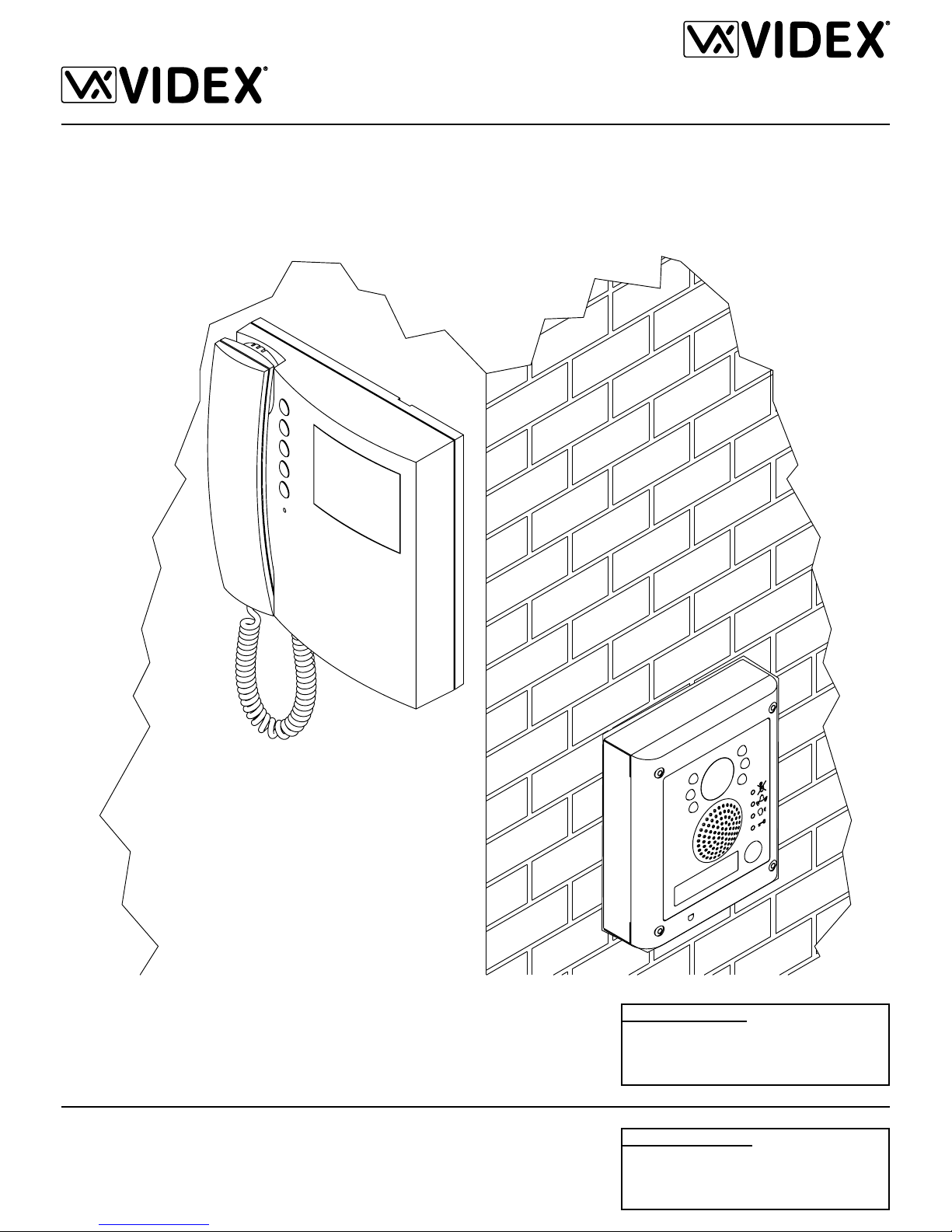
The VK4K series is a new range of videokits that use the 4000 series external
door station and the 3000 series videophone which is specific for this range of
videokit. The camera / audio unit is the size of a single 4000 series module and
is available in either flush (VK4K) or surface (VK4K-S) mounting versions.
As a result of using microprocessor technology in the door panel and videophone, a number of additional features have been added to enhance the operation of the videokits and give greater feedback to the visitor and user.
•Disability friendly, visual and acoustic signals from the door panel to inform the
visitor of call status (call made, ringing, speak, door open).
•Programmable door open and conversation time.
•Expandable to 4 entrance panels (requires an additional relay Art.506N for
each entrance panel).
•Connections for a push to exit button.
•Two methods of operating the electric lock:- 1) Dry contact relay, 2) capacitor
discharge circuit.
•Facility for the connection of a codelock Art.4800, display module Art.4820,
stand-alone proximity reader Art. 4850 or stand-alone biometric reader Art.
4821 etc.
•Programmable number of call tone rings from 2 to a maximum of 8.
•Input for local door bell push button.
•Programmable timed privacy function from 15 minutes to a maximum of 8
hours.
•Door open status LED (additional wire required from the door to the videophone)
•Up to 4 videophones can be connected in parallel, all with intercommunication
facility.
•Videophones can have a maximum of two additional audio telephone handsets
connected in parallel.
•Camera recall on all systems, with selective recall on systems with multiple
entrances.
•Door panel camera can be adjusted horizontally and vertically (10 degrees).
The kit comprises of.
1 Camera unit Art.4833-1. The unit includes a high quality B&W CCD camera
with auto iris lens, infrared LEDs for illumination, audio amplifiers and one
button speaker unit;
1 Module front support with flush mounting box Art.4851 (the surface version
of the kit VK4K-S includes the relevant surface mounting box Art.4881);
1 B&W videophone Art.3356 with 4” flat screen complete with mounting plate
and PCB connection Art.3980;
1 Power transformer Art.850K boxed in 5 Module A Type DIN BOX.
As VK4K and VK4K-S but with Art.3456 colour videophone with 3,5” LCD TFT
monitor and colour camera unit Art.4833colour with white light illumination
LEDs.
As VK4K and VK4K-S but with B&W videophone Art.3556 with memory board
and special power supply Art.850K/MV.
As VK4K,VK4K-S, CVK4K and CVK4K-S but with flush mounting box Art.4852,
stand-alone codelock module Art.4800. The user can open the door from outside by typing the relevant access code into the keypad.
As VK4K,VK4K-S, CVK4K and CVK4K-S but with flush mounting box Art.4852,
stand-alone proximity keys reader module Art.4850 and 3 proximity keys card
format Art.955/C. The user can open the door from the outside by simply presenting a card/fob to the external reader.
As VK4K,VK4K-S, CVK4K and CVK4K-S but with flush mounting box Art.4852
and a stand-alone fingerprint reader module Art.4821. The user can open the
door from the outside simply by swiping their finger on the reader. No door keys,
codes or fobs to forget.
I videokit della serie VK4K fanno parte di una nuova linea che utilizza il posto
esterno con design Serie 4000. Il videocitofono fornito a corredo è Serie 3000 in
una versione espressamente progettata per questa linea di videokit. L’unità di ripresa ha le dimensioni di un modulo della Serie 4000 ed è corredato dal relativo
supporto da incasso (VK4K) o superficie (VK4K-S) in base alla versione del kit.
Grazie all’impiego della tecnologia a microprocessore sia nel modulo portiere
elettrico - unità di ripresa che nel videocitofono, i kit di questa linea offrono numerose funzioni innovative tra le quali troviamo:
•Segnalazioni acustiche e visive in merito al funzionamento del sistema in aiuto
degli utenti diversamente abili;
•Possibilità di utilizzo della serratura tramite relè a contatti puliti o scarica capacitiva;
•Possibilità di collegare un pulsante per l’apertura diretta della porta d’ingresso;
•Possibilità di programmazione dei tempi d’apertura porta e conversazione;
•Possibilità di collegare fino a 4 ingressi con l’ausilio di relè d’asservimento
Art.506N;
•Predisposizione per il collegamento del modulo display Art.4820 e del lettore
chiavi di prossimità stand-alone Art.4850;
•Possibilità di programmare il numero di squilli da un minimo di 2 ad un massimo di 8;
•Ingresso per chiamata di piano-locale;
•Possibilità di monitorare lo stato d’apertura-chiusura della porta tramite apposi-
to LED presente sul videocitofono (è richiesto un conduttore addizionale dalla
porta verso il videocitofono);
•Possibilità di programmare la funzione privacy da un minimo di 15 minuti ad
un massimo di 8 ore;
•Predisposizione per il collegamento facilitato di un citofono in parallelo (max 2
indipendentemente dal numero di videocitofoni in parallelo);
•Possibilità di collegare fino a 4 videocitofoni in parallelo con funzione di intercomunicazione;
•Auto-accensione selettiva in caso di più ingressi;
•Brandeggio telecamera regolabile sia verticalmente che orizzontalmente con
un’escursione massima di 10º.
Il kit comprende:
1 Unità di ripresa Art.4833-1. L’unità incorpora una telecamera bianco e nero
CCD autofocus di alta qualità, i LED d’illuminazione agli infrarossi, la circuiteria di amplificazione audio e il portiere elettrico con un pulsante di chiamata;
1 Supporto da incasso ad 1 modulo Art.4851 (nella versione da superficie
VK4K-S questo articolo è rimpiazzato dalla relativa scatola da superficie
Art.4881);
1 Videocitofono Art.3356 Bianco & Nero con schermo piatto da 4” completo di
piastra di fissaggio a parete e scheda di connessione Art.3980;
1 Trasformatore di alimentazione Art.850K (Cont. DIN 5 Moduli tipo A).
Come i kit VK4K e VK4K-S, ma con videocitofono a colori Art.3456 con monitor
TFT da 3,5” e unità di ripresa Art.4833colour con telecamera a colori e LED
d’illuminazione ad emissione di luce bianca.
Come i kit VK4K e VK4K-S, ma con videocitofono bianco e nero Art.3556 completo di memoria video ed alimentatore specifico Art.850K/MV.
Come i kit VK4K, VK4K-S, CVK4K e CVK4K-S ma con supporto da incasso a 2
moduli Art.4852, modulo tastiera digitale a codice stand-alone Art.4800. L’utente può aprire la porta digitando l’apposito codice tramite la tastiera.
Come i kit VK4K, VK4K-S, CVK4K e CVK4K-S ma con supporto da incasso a
2 moduli Art.4852, modulo lettore chiavi di prossimità stand-alone Art.4850 e 3
chiavi di prossimità in formato card Art.955/C. L’utente può aprire la porta avvicinando la propria chiave di prossimità al lettore.
Come i kit VK4K, VK4K-S, CVK4K e CVK4K-S ma con supporto da incasso a 2
moduli Art.4852 e modulo lettore d’impronte stand-alone Art.4821. L’utente può
aprire la porta d’ingresso utilizzando semplicemente le proprie dita. Non sarà più
possibile dimenticare le chiavi di casa.
VK4K, VK4K-S
Videokit Monofamiliare con videocitofono e telecamera bianco e nero
VK4K, VK4K-S
One way videoki with B&W videophone and camera
CVK4K, CVK4K-S
Videokit Monofamiliare con videocitofono e telecamera a colori
CVK4K, CVK4K-S
One way videoki with colour videophone and camera
VK4K/MV, VK4K-S/MV
Videokit Monofamiliare con videocitofono+memoria e telecamera bianco e nero
VK4K/MV, VK4K-S/MV
One way videokit with B&W videophone with memory and camera
VKX4K, VKX4K-S, CVKX4K, CVKX4K-S
Videokit Monofamiliare (bianco e nero o colori) più lettore chiavi di prossimità
VKX4K, VKX4K-S, CVKX4K, CVKX4K-S
One way videokit (colour or B&W) plus a proximity key reader module
VKFP4K, VKFP4K-S, CVKFP4K, CVKFP4K-S
Videokit Monofamiliare (bianco e nero o colori) più lettore d’impronte
VKFP4K, VKFP4K-S, CVKFP4K, CVKX4K-S
One way videokit (colour or B&W) plus a fingerprint reader module
VKC4K, VKC4K-S, CVKC4K, CVKC4K-S
Videokit Monofamiliare (bianco e nero o colori) più tastiera digitale
VKC4K, VKC4K-S, CVKC4K, CVKC4K-S
One way videokit (colour or B&W) plus a codelock module
VK4K
3
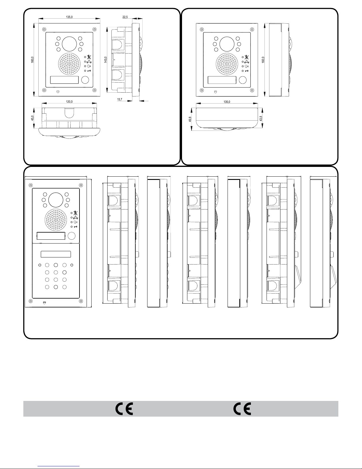
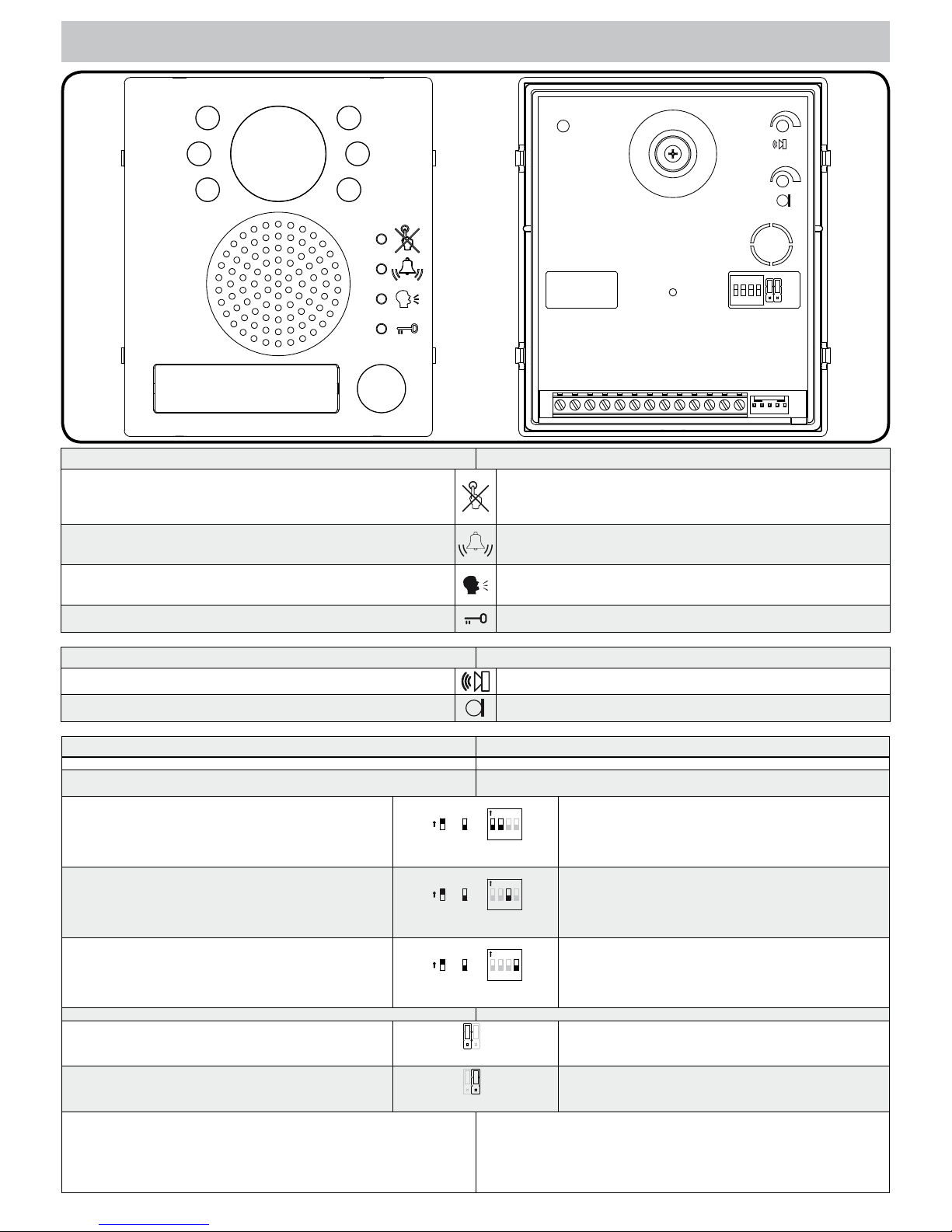
Flush Door Station
Posto Esterno da Incasso
VK4K
CVK4K
VK4K/MV
Surface Door Station
Posto Esterno da Superficie
VK4K-S
CVK4K-S
VK4K/MV-S
45
23
2
6
3
50135
2
8
0
45
24
2
6
3
51
45 31
2
6
3
58
VKC4K
VKX4K
VKFP4K
VKC4K VKX4K VKFP4K
MARKINGMARCATURA
La marcatura CE di conformità indica che il prodotto soddisfa i requisiti delle Direttive della Comunità Economica Europea in vigore (in particolare quelle 73/23/
CEE e 93/68/CEE e Compatibilità elettromagnetica 89/336) ad esso applicabili.
La marcatura CE, apposta sui prodotti dal fabbricante (o da un suo mandatario)
sotto la propria responsabilità, è stata creata con l’intento di eliminare gli ostacoli
alla circolazione dei prodotti all’interno degli Stati membri dell’Unione Europea
armonizzando diverse normative a carattere nazionale.
CE conformity marking indicates that the product respects the requirements of
the applicable European Community Directives in force (specifically 73/23/EEC,
93/68/EEC and the Electromagnetic Compatibility Directive 89/336).
CE marking is applied by the manufacturer (or party delegated to do so by the
manufacturer) under their own responsibility. It was created to eliminate obstacles to the circulation of products in European Union Member States by harmonising different national standards.
Tutti i videokit indicati di lato sono disponibili anche in
versione bi-familiare con 2 videocitofoni, 2 trasformatori e unità di ripresa a 2 pulsanti Art.4833-1D: VK4K-2,
VK4K-2S, CVK4K-2, CVK4K-2S, VK4K-2/MV, V K4K-2S/MV,
VKC4K-2, VKC4K-2S, CVKC4K-2, CVKC4K-2S, VKX4K-2,
VKX4K-2S, CVKX4K-2, CVKX4K-2S, VKFP4K-2, VKFP4K-2S,
CVKFP4K-2, CVKFP4K-2S.
All videokit above are available in two button version with 2
videophones, 2 power transformers and camera unit with 2
call push buttons Art.4833-1D: VK4K-2, VK4K-2S, CVK4K-2,
CVK4K-2S, VK4K-2/MV, V K4K-2S/MV, VKC4K-2, VKC4K-2S,
CVKC4K-2, CVKC4K-2S, VKX4K-2, VKX4K-2S, CVKX4K-2,
CVKX4K-2S, VKFP4K-2, VKFP4K-2S, CVKFP4K-2 and
CVKFP4K-2S.
VK4K
4
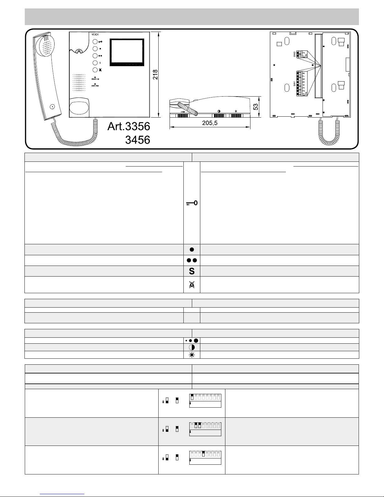
VIDEOCITOFONO
Pulsanti, LED, Controlli, Impostazioni e Segnali
VIDEOPHONE
Push Buttons, LEDs, Controls, Settings & Signals
Pulsanti Push Buttons
Pulsante apri-porta/chiamata intercomunicante. Come pulsante di chiamata
intercomunicante è operativo solo quando il sistema è in stand-by.
La modalità intercomunicante dipende dalla posizione dello switch 4
dell’SW1:
OFF Intercomunicazione solo tra appartamenti - sollevare la cornetta e
premere il pulsante chiave per chiamare il videocitofono nell’altro
appartamento. Un eventuale tono di occupato segnala che l’altro
appartamento è in conversazione con l’esterno.
ON Intercomuncazione solo tra videocitofoni dello stesso apparta-
mento - sollevare la cornetta e premere il pulsante chiave 1, 2,
3 o 4 volte per chiamare il videocitofono con indirizzo d’interno
1, 2, 3 o 4.
Qualsiasi conversazione intercomunicante è sempre interrotta da una chiamata esterna.
Door-open / intercommunicating call button. Intercommunication only works
when the system is in stand-by condition.
Switch 4 of the SW1 dipswitch selects the type of intercommunication:
OFF Intercommunication between two apartments - pick up the hand-
set and press the key button to call the videophone(s) in the other
apartment. A busy tone will signal that the other videophone is in
conversation with the doorstation and so cannot be called.
ON Intercommunication between videophones in the same apartment
- pick up the handset and press the key button one, two, three or
four times to call videophone with extension address 1, 2, 3 or 4
(Set on dip-switch 2&3 of SW1).
Any intercommunicating conversation is always interrupted by an external
call (i.e. External calls take priority).
Pulsante di auto-accensione. In presenza di più ingressi, premere 1, 2, 3 o
4 volte per attivare l’ingresso 1, 2, 3 o 4.
Camera recall button. In case of more entrances, press the button 1, 2, 3 or
4 times to switch on door unit with ID 1, 2, 3 or 4.
Pulsante di servizio. Quando premuto collega internamente il relativo morsetto “17” con il morsetto comune “18”.
Service push button. When pressed shorts terminal “17” to the common terminal 18.
Pulsante di servizio. Quando premuto collega internamente il relativo morsetto “16” con il morsetto comune “18”.
Service push button. When pressed shorts terminal “16” to the common terminal 18.
Pulsante “privacy” ON-OFF. Il pulsante attiva/disattiva la funzione “privacy”,
in ogni caso la funzione si disattiva automaticamente allo scadere del tempo
programmato.
Privacy ON-OFF button. Enable/Disable the privacy service, the service is
automatically disabled when the programmed privacy time expires.
LED LEDs
LED “PRIVACY ON”. Acceso quando il servizio è abilitato Red “PRIVACY ON” LED. The LED is on when the function is enabled.
LED “DOOR OPEN”. Fatti gli opportuni collegamenti, questo led indica lo
stato della porta: acceso = aperta, spento = chiusa.
Green
“DOOR OPEN” LED. If the required connections are made, the LED shows
the open/close status of the door: ON = Open, OFF = Closed.
Controlli Controls
Regolazione volume (3 livelli) della nota di chiamata. Call tone volume control (3 levels).
Regolazione del contrasto.
Contrast control. To adjust move from left to right.
Regolazione della luminosità.
Brightness control. To adjust move from left to right.
Impostazioni (Dip-Switch) Settings (Dip-Switches)
L’impostazione del videocitofono viene eseguita tramite i 2 dip-switch accessibili
dalla parte posteriore dello stesso.
The videophone setup is carried out by the 2 dip-switches accessible from the
rear of the videophone.
DIP-SWITCH a 8 VIE (SW1) 8 WAY DIP-SWITCH (SW1)
Switch 1 Indirizzo d’Appartamento
OFF 1
ON 2
1 2 3 4 5 6 7 8
ON
SW1
ON
=ON =OFF
Switch 1 Apartment Address
OFF 1
ON 2
Switch 2,3 Indirizzo Interno
OFF OFF 1
ON OFF 2
OFF ON 3
ON ON 4
1 2 3 4 5 6 7 8
ON
SW1
ON
=ON =OFF
Switches 2,3 Extension Address
OFF OFF 1
ON OFF 2
OFF ON 3
ON ON 4
Switch 4 Intercomunicazione
OFF tra i videocitofoni dei due appartamenti
ON tra i videocitofoni dello stesso appartamento
1 2 3 4 5 6 7 8
ON
SW1
ON
=ON =OFF
Switch 4 Intercommunication
OFF Between videophones of the two apartment
ON Between videophones in the same apartment
VK4K
5
Switch 5,6 Numero di squilli
OFF OFF 2
ON OFF 4
OFF ON 6
ON ON 8
1 2 3 4 5 6 7 8
ON
SW1
ON
=ON =OFF
Switches 5,6 Number of Rings
OFF OFF 2
ON OFF 4
OFF ON 6
ON ON 8
Switch 7,8 Durata Privacy
OFF OFF 15 minuti
ON OFF 1 ora
OFF ON 4 ore
ON ON 8 ore
1 2 3 4 5 6 7 8
ON
SW1
ON
=ON =OFF
Switches 7,8 Privacy duration time
OFF OFF 15 minutes
ON OFF 1 hours
OFF ON 4 hours
ON ON 8 hours
DIP-SWITCH a 2 VIE (SW2) 2 WAY DIP-SWITCH (SW2)
Il dip-switch a 2 vie serve per adattare l’impedenza del segnale
video. L’impostazione di default è “ON” per entrambi gli switch
(75 Ohm): in presenza di più videocitofoni collegati in parallelo
(senza distributore video), gli switch devono rimanere entrambi
ad “ON” solo per l’ultimo (in ordine di connessione) videocitofono, mentre per tutti gli altri devono essere impostati entrambi
ad “OFF”.
1 2
ON
SW2
ON
=ON =OFF
1 2
ON
SW2
The two way dip-switch adjusts the impedance of video signal.
The default setting is “ON” for both switches (75 Ohm): when
there are more videophones in parallel connection (without
video distributor) both switches must be “ON” only on the last
videophone (looking at the connection order) while for all other
videophones both switches must be set to “OFF”.
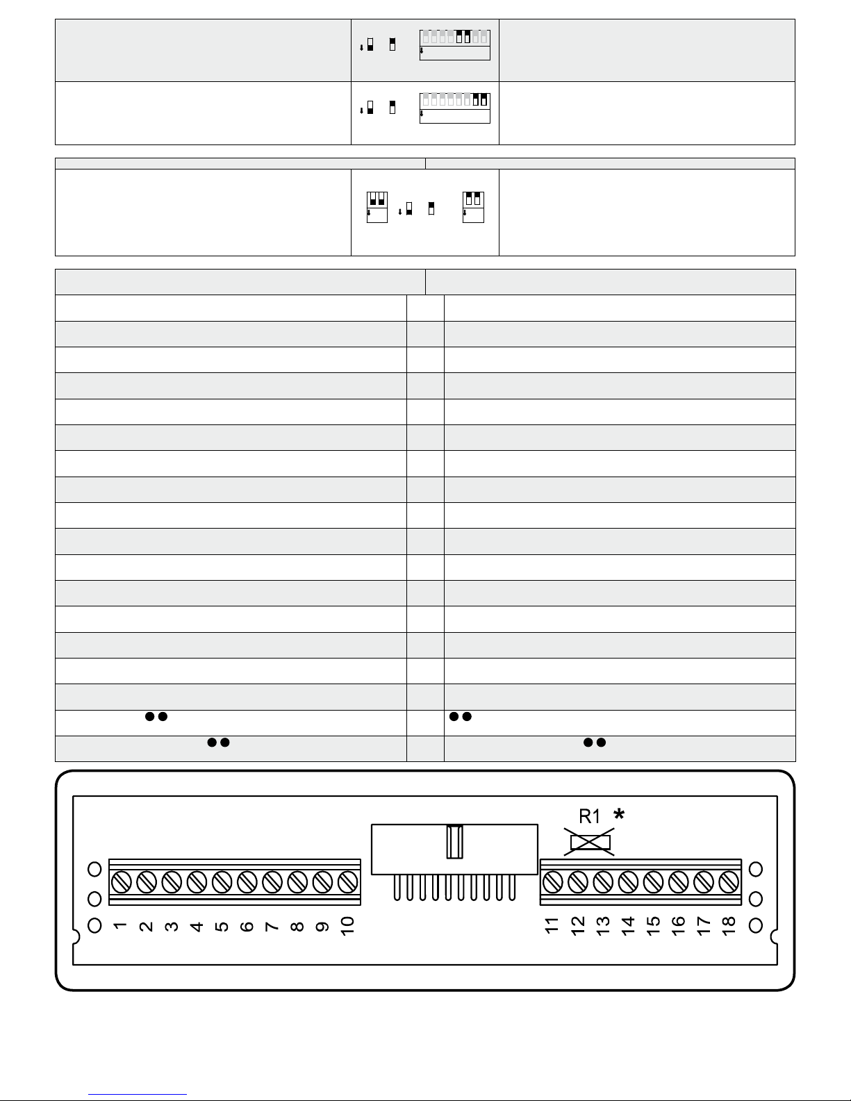
Segnali (Art.3980)
Signals (Art.3980)
Uscita fonia proveniente dal microfono della cornetta e segnale dati (12V
circa in stand-by, 5V circa in conversazione)
1
Speech line output from handset’s microphone and data signal (About 12V
in stand-by, about 5V in conversation)
Ingresso fonia verso l’altoparlante della cornetta (12V circa in stand-by, 3V
circa in conversazione)
2
Speech line input toward the handset’s loudspeaker (About 12V in stand-by,
about 3V in conversation)
Ingresso fonia verso l’altoparlante del citofono collegato in parallelo (12V
circa in stand-by e 3V circa in conversazione)
3
Speech line input toward the loudspeaker of the parallel telephone (About
12V in stand-by, about 3V in conversation)
Segnale video bilanciato 1 sinc.-
4
Balanced video signal 1 sync.-
Segnale video bilanciato 2 sinc.+
5
Balanced video signal 2 sync.+
Ingresso d’alimentazione – riferimento di massa
6
Power supply ground input
Ingresso d’alimentazione 12Vdc 150mA per videocitofono con memoria video (solo per il videocitofono 3556)
7
12Vdc 150mA power input to supply memory board, only on 3556 videophone
Ingresso/Uscita 20Vdc (come ingresso 16÷20Vdc 0,5A – come uscita 20Vdc
0,5A max)
8
20Vdc Input/Output (As input 16÷20Vdc 0,5A – as output 20Vdc 0,5A max)
Ingresso d’alimentazione 24Vac 1A max
9
24Vac 1A max power input
Ingresso d’alimentazione 0Vac
10
0Vac power input
Uscita riferimento di massa citofono in parallelo
11
Output ground for parallel telephone
Uscita tono di chiamata per citofono in parallelo
12
Output call tone for parallel telephone
Ingresso comando apri-porta citofono in parallelo
13
Input for door-open command from parallel telephone
Ingresso 12Vdc per LED di segnalazione porta aperta
14
12Vdc input for door-open LED
Ingresso per chiamata locale (5V stand by, 0V in funzione)
15
Local call input
Contatto pulsante “S” riferito al morsetto “18” a pulsante premuto
16
“S” button contact shorts to terminal “18” when pressed
Contatto pulsante “
” riferito al morsetto “18” a pulsante premuto
17
“ ”button contact shorts to terminal “18” when pressed
Contatto comune pulsanti “S” e “
”
18
Common contact for “S” and “ ”buttons
* Rimuovere la resistenza R1 se presente * Remove R1 resistor if present
VK4K
6
PORTIERE ELETTRICO
LED, Controlli, Impostazioni e Segnali
SPEAKER UNIT
LEDs, Controls, Settings & Signals
sw
NONCCPTESLBSV1V221
12Vout
-
+V
J1 J2
1 2 3 4
ON
DATA
H
L
LED LEDs
Se acceso, indica che non è possibile chiamare a causa di una chiamata o
conversazione in corso dal posto esterno in uso o da un altro posto esterno
in caso di sistemi a più ingressi. Il LED si spegne con l’impianto a riposo
(nessuna conversazione o chiamata in corso).
When illuminated, indicates that it is not possible to make a call because
a call or a conversation is in progress (from the outdoor station from which
you are calling or from another outdoor station on systems with multiple
entrances). The LED will be off when the system is in stand-by.
Se acceso, indica che è in corso la chiamata dal posto esterno che si sta
utilizzando. Il LED si spegne alla risposta dell’utente chiamato o al raggiungimento del numero di squilli programmati.
If illuminated, indicates that the call from the outdoor station is in progress.
The LED will switch OFF when the call is answered or after the programmed
number of rings.
Se acceso, indica che è in corso la chiamata dal posto esterno che si sta
utilizzando. Il LED si spegne alla risposta dell’utente chiamato o al raggiungimento del numero di squilli programmati.
If illuminated, indicates that it is possible to speak because the call has been
answered. The LED will switch OFF at the end of a conversation (or at the
end of the conversation time).
Se acceso, indica che l'utente chiamato ha aperto la porta. Il LED resta
acceso per tutto il “tempo d'apertura porta” programmato.
If illuminated, indicates that the door lock has been operated. It will switch
OFF at the end of the programmed “door opening” time.
Controlli (volume microfono e speaker) Controls (speaker & microphone volume)
Trimmer di regolazione del volume dello speaker. Ruotare in senso orario
per aumentare o antiorario per diminuire.
Trimmer to adjust the speaker volume. Rotate clockwise to increase or anticlockwise to decrease.
Trimmer di regolazione del volume del microfono. Ruotare in senso orario
per aumentare o antiorario per diminuire.
Trimmer to adjust the microphone volume. Rotate clockwise to increase or
anticlockwise to decrease.
Impostazioni (Dip-switch e Jumper) Settings (dip-switch & Jumpers)
DIP-SWITCH a 4 VIE 4 WAY DIP-SWITCH
I primi 2 switch permettono di configurare l’indirizzo del posto esterno: l’indirizzo
è necessario per l’auto-accensione selettiva in caso di 2 o più posti esterni
First two switches are used to set the speaker unit address: the speaker unit address is required for camera recall operation on 2 or more entrance systems.
Switch 1,2 Indirizzo Unità
OFF OFF 1
ON OFF 2
OFF ON 3
ON ON 4
ON
sw
1 2 3 4
ON
=OFF=ON
Switches 1,2 Unit Address
OFF OFF 1
ON OFF 2
OFF ON 3
ON ON 4
Switch 3 Tempo di Conversazione
OFF 60 secondi
ON 120 secondi
ON
sw
1 2 3 4
ON
=OFF=ON
Switch 3 Conversation Time
OFF 60 seconds
ON 120 seconds
Switch 4 Tempo d’apertura porta (J2 posizione “L”)
OFF 2 secondi
ON 6 secondi
ON
sw
1 2 3 4
ON
=OFF=ON
Switch 4 Door opening time (J2 = “L” position)
OFF 2 seconds
ON 6 seconds
Jumper J1, J2 Jumpers J1, J2
Posizione J1 Volume tono di conferma chiamata
H Alto
L Basso
J1 J2
H
L
J1 Position Call reassurance tone volume
H High
L Low
Posizione J2 Funzionamento relè apri-porta
H Scarica capacitiva
L Contatti puliti
J1 J2
H
L
J2 Position Door open relay operating mode
H Capacitor discharge
L Dry contacts
Quando la modalità è impostata su “scarica capacitiva”, un terminale della serratura va collegato a massa, mentre l’altro va collegato al morsetto “NO” che
fornisce una tensione temporanea al ricevimento del comando d’apertura porta.
Nella modalità contatti puliti, al ricevimento del comando d’apertura porta il contatto “NO” chiude verso “C”.
When the door open relay operating mode is set to “capacitor discharge”, one
terminal of the electric lock must be connected to ground while the second must
be connected to “NO” terminal. The “NO” terminal will supply a temporary voltage when the speaker unit receives the door open command. In “dry contacts”
mode the “NO” terminal is internally linked to “C” terminal when the speaker unit
receive the door open command.

VK4K
7
Segnali (Morsettiera) Signals (Terminals)
Ingresso d’alimentazione 16÷20Vdc
+V
Power input 16÷20Vdc
Alimentazione riferimento di massa
-
Power input ground
Uscita 12Vdc. 0,3A max. per alimentazione accessori
12Vout
12Vdc. 0,3A max. output to supply accessiories
Ingresso fonia verso l’altoparlante del portiele elettrico e segnale dati (12V
circa in stand-by, 5V circa in conversazione)
1
Speech line input toward the loudspeaker and data signal (about 12V in
stand-by, about 5V with a conversation in progress)
Uscita fonia dal microfono del portiere elettrico (12V circa in stand-by, 3V
circa in conversazione)
2
Speech line output from the microphone (about 12V in stand-by, about 3V
with a conversation in progress)
Uscita segnale video bilanciato sinc.-
V1
Balanced video signal sync.-
Uscita segnale video bilanciato sinc.+
V2
Balanced video signal sync.+
Ingresso/Uscita segnale di linea occupata (12Vcirca in stand-by, 0V circa
con chiamata in corso)
BS
Input/Output busy signal (about 12V in stand-by, about 0V with a call in
progress)
Uscita segnale per attivazione relè scambio video (attivo basso con chiamata in corso)
SL
Active low output to enable the enslavement relay for video signal exchange
(active with a call in progress)
Ingresso attivo basso di comando diretto per il relè apri-porta
PTE
Active low input to control directly the door open relay
Relè apri-porta contatto comune
C
Door open relay common contact
Relè apri-porta contatto normalmente chiuso
NC
Door open relay normally closed contact
Relè apri-porta contatto normalmente aperto
NO
Door open relay normally open contact

VK4K
8
Collegamento alla Rete Elettrica,
Installazione dell’Alimentatore
Connection to Mains,
Power Supply Mounting Instructions
La realizzazione dell’impianto deve essere eseguita nel rispetto delle vigenti normative nazionali, in particolare si raccomanda di:
•Collegare l’impianto alla rete elettrica tramite un dispositivo di interruzione omnipolare che abbia una distanza di separazione del contatto di almeno 3mm
per ciascun polo e che sia in grado di disconnettere tutti i poli simultaneamente;
•Il dispositivo di interruzione omnipolare deve essere posizionato in un luogo
tale da consentirne un facile accesso in caso di necessità.
INSTALLAZIONE DELL’ALIMENTATORE
•Rimuovere i coperchi copri-morsetti svitando le relative viti e tirandoli verso
l’alto;
•Fissare l’alimentatore su barra DIN o direttamente a parete utilizzando le viti ed
i relativi tasselli ad espansione forniti a corredo;
•Togliere la tensione di rete tramite il dispositivo sopra indicato ed eseguire le
connessioni come previsto dagli schemi proposti (la connessione verso la rete
va effettuata in base alla tensione disponibile 127 o 230Vac).
•Verificare che non vi siano errori di connessione e che i fili siano ben serrati
nei morsetti;
•Inserire a scatto i coperchi copri-morsetti e fissarli tramite le relative viti;
•Eseguiti tutti i collegamenti, dare tensione all’impianto.
POSTO ESTERNO DA SUPERFICIE
1. Appoggiare la scatola da superficie alla parete lasciando circa 165-170cm
tra la parte alta della scatola ed il terreno come mostrato in figura 1 quindi
prendere i riferimenti per i fori di fissaggio tenendo presente che il gruppo di
fili e (fig.2) deve passare attraverso l’apertura d presente sulla scatola da superficie. Se non indicato, il verso di montaggio della scatola deve essere
tale da far rimanere la cerniera sulla sinistra;
2. Come mostrato in figura 2, realizzare i fori di fissaggio a, inserire al loro
interno i tasselli ad espansione b e, facendo passare i fili di collegamento e
attraverso l’apertura d, fissare la scatola da superficie c alla parete utilizzando le viti f;
3. Inserire il modulo g nel supporto h come mostrato in figura 3;
4. Prima di agganciare alla scatola da superficie il supporto completo di modulo,
inserire i fermi anti-effrazione i come mostrato in figura 4;
5. Muovendo il supporto h come mostrato dalle frecce di figura 5, procedere
all’aggancio dello stesso alla scatola da superficie c. Il perno l deve inserirsi
nel relativo alloggiamento m come mostrato in figura 6;
6. Come mostrato in figura 7, tirare il supporto moduli h indietro compiendo
contemporaneamente un leggero movimento a sinistra come suggerito dalle
frecce;
7. Come mostrato in figura 8, ruotare il supporto moduli h nella direzione con-
sigliata dalla freccia e provvedere ad agganciare il fermo n all’alloggiamento
m del perno. Assicurato il supporto alla scatola da superficie, svolgere le
seguenti operazioni:
•eseguire le opportune configurazioni dell’unità tramite i 2 jumper ed il dipswitch a 4 vie accessibili dall’apertura o
•effettuare i necessari collegamenti con l’ausilio del giravite (lato piatto della
lama) fornito a corredo;
•regolare l’angolo di ripresa della telecamera agendo sulla vite p;
8. Ad impianto testato e funzionante, procedendo a ritroso delicatamente, chiudere e fissare il supporto moduli alla scatola da superficie utilizzando il giravite s (lato torx della lama) e le viti q come mostrato in figura 9. Nota bene:
non serrare le viti più del necessario.
POSTO ESTERNO DA INCASSO
Se il posto esterno è da incasso occorre procedere come di seguito indicato:
1. Dopo aver opportunamente protetto i fori di fissaggio per il supporto moduli,
murare la scatola da incasso ad una altezza tale da avere circa 165-170cm
tra la parte alta della scatola e il terreno avendo cura di far passare il gruppo
di fili e (fig.2) attraverso uno dei fori precedentemente aperti sul fondo della
scatola. Se non indicato sul fondo della scatola, il verso di muratura
deve essere tale da lasciare la cerniera sulla sinistra. Fare attenzione
affinché la scatola sia murata a filo muro finito;
2. Proseguire dal passo 3 della installazione da superficie tenendo presente
che al punto 7 il fermo n va agganciato come mostrato in figura 10.
Note
La lama del giravite fornito a corredo ha due punte, una piatta ed una torx. Sfilare la punta e reinserirla nel manico scegliendo il lato desiderato
The system must be installed according to national rules in force, in particular
we recommend to:
•Connect the system to the mains through an all-pole circuit breaker which shall
have contact separation of at least 3mm in each pole and shall disconnect all
poles simultaneously;
•The all-pole circuit breaker shall be placed for easy access and the switch shall
remain readily operable.
POWER SUPPLY INSTALLATION
•Remove the terminal side covers by unscrewing the retaining screws;
•Fix the power supply to a DIN bar or directly to the wall using two expansion
type screws;
•Switch off the mains using the circuit breaker mentioned above and then make
the connections as shown on the installation diagrams;
•Check the connections and secure the wires into the terminals;
•Replace the terminal covers and fix them using the relevant screws;
•When all connections are made, restore the mains.
SURFACE DOOR STATION
1. Place the surface box against the wall (165-170cm between the top of the
box and the floor lever as show in figure 1) and mark the fixing holes for the
wall plugs and hole for the cables e (fig.2). Observe the orientation of the
box with the hinge on the left;
2. As shown on figure 2, drill the fixing holes a, insert the wall plugs b and feed
the cables e through the surface box opening d, fix surface box c to the wall
using the screws f;
3. Hook the module g in the support frame h as shown in figure 3;
4. Before the installation of the module support frame, fit the two anti-tampering
locks provided as shown in figure 4;
5. As shown in figure 5, hook the module support frame h (complete with mod-
ules) to surface box c moving the frame as suggested from pointers. Ensure
that the pivot l (fig.5) goes inside the relevant housing m as shown in figure
6.
6. As shown in figure 7, pull back the module support frame h while moving it
slightly to the left as suggested by the pointers;
7. As shown in figure 8, open the module support frame h as suggested by the
pointer, hook the hinge lock n to the hinge m. When the support frame is
hooked to the surface box, do the following operations:
•make the required settings operating the two jumpers and the 4 way dipswitch accessible from the opening o (fig.8)
•make the required connections using the screwdriver provided (blade flat
side);
•adjust the camera viewing angle by operating the screw p (fig.8);
8. When the system has been tested and is working correctly, move back the
module support frame carefully, fix it to the surface box using the provided
screwdriver s (blade torx side) and the pin machine torx screws q as shown in
figure 9. Note: do not over tighten the screws more than is necessary.
FLUSH DOOR STATION
If the door station is a flush, carry out the following:
1. Protect the module support frame fixing holes from dust then embed the back
box into the wall (165-170cm between the top of the box and the floor level as
shown on the figure 1) feeding the cables e (fig.2) through a previous opened
hole in the box. Observe the direction of the box ensuring the hinge is
on the left and take care that the box profile is in line with the finished
wall profile;
2. Continue from step 3 of surface mounting, but at step 6 hook the hinge lock
n as shown on figure 10.
Notes
The screwdriver’s blade has two sides, one flat and one torx, to select one of
them unplug the blade from the screwdriver body and plug it into the required
side.
Installazione Posto Esterno Door Station Mounting
 Loading...