

Videx SMVK1, SMVK1/MV, CSMVK1 Owner's Manual
Factory - Office
VIDEX ELECTRONICS S.p.A. Via del lavoro,1 63020 MONTEGIBERTO (AP) - ITALY
Phone: (+39) 0734 - 631669 Fax: (+39) 0734 - 632475 www.videx.it e-mail: info@videx.it
We recommend
This equipment is installed by a
Competent Electrician, Security or
Communications Engineer
Norme Tecniche
Owner’s Manual
One way, two way
Monofamiliari e Bifamiliari
SMART
SERIES VIDEOKITS
VIDEOKIT SERIE
SMART
!
!
!
!
!
!
!
!
C
C
C
Svitare la vite alla base della placca frontale impiegando un cacciavite a
croce,
Rimuovere la placca frontale facendole prima compiere un leggero
movimento indietro (3-4mm) e quindi sollevandola nella parte inferiore
come mostratorispettivamente nelle figure2 e 3.
Rimuovere il supporto per lo speaker (lasciando lo speaker inserito)
tirandolo leggermente verso l’alto come mostrato in figura 4, fino a
raggiungere la condizione di figura5 (supporto sganciato e rivolto verso il
basso).
Prendere i riferimenti per i fori di fissaggio e per il passaggio dei fili (Rif.H
figura 5), posizionando il posto esterno alle quote mostrate in figura 6
(165-170cm dalla parte superiore del posto esterno al terreno). Qualora i
fili fossero già passati, prendere i riferimenti per ifori di fissaggio tenendo
presente che i conduttori dovranno fuoriuscire dall’apposita fessura del
posto esterno
come mostrato infigura 1.
(Rif.H figura 5). Per collegare agevolmente i conduttori, si
raccomanda di lasciare una lunghezza di 5cm a partire da filo muro (vedi
figura 7).
Eseguire i 4 fori di fissaggio dal diametro di 6mm (Rif.A figura 7); inserire
nei fori i 4 tasselli ad espansione forniti a corredo (Rif.B figura 7);
ricordando di far passare i conduttori attraverso l’apposita fessura (Rif.H
figura 5) del posto esterno, appoggiare l’unità (Rif.C figura 7) al muro e
fissarla con le 4 viti (Rif.D figura 7) fornite a corredo, tramite un cacciavite
a croce.
Fissato a parete il posto esterno, procedere alla realizzazione dei
collegamenti inserendo i conduttori (Rif.E figura 8) nelle apposite
morsettiere (Riff.F e G figura 8). Si ricorda che i collegamenti dovranno
essere eseguiti in base agli schemi di installazione forniti a corredo.
Serrare i conduttori all’interno dei morsetti utilizzando un cacciavite a
taglio. Per l’operazione di inserimento dei fili all’interno dei morsetti si
consiglia l’utilizzo diapposite pinzette (Figura8).
Eseguiti i collegamenti, ricollocare il supporto per lo speaker nel suo
alloggiamento (condizione di figura 4), quindi procedere al collaudo
dell’impianto ed alla regolazione del brandeggio della telecamera. Per
regolare il brandeggio muovere delicatamente la telecamera secondo le
direzioni mostrate infigura 8 (Rif.J).
Terminato ilcollaudo, chiudereil posto esterno fissando laplacca frontale.
Per fissare laplacca frontale:
posizionarla come mostrato in figura 3 (lasciando circa 3-4mm tra la
parte superiore della placca e la superficie di contatto con la base
porta componenti) e successivamente avvicinarla completamente
alla base compiendo un movimento in senso contrario a quello della
freccia di figura3;
spingere la placca leggermente verso l’alto, compiendo un
movimento in senso contrario a quello della freccia di figura 2, fino a
portarne la partesuperiore a contattocon la baseporta componenti;
avvitare la vite alla basedella placcafrontale ruotando il cacciavite in
senso inverso aquello della frecciadi figura 1.
I videokit SMVK1 sono forniti con i videocitofoni della
serie 3000 ed il posto esterno Art.331K. Quest’ultimo ha
subito degli aggiornamenti
nel design, nell’elettronica e nella meccanica
che gli hanno conferito una maggiore resistenza agli
agenti atmosferici. Anche il meccanismo di brandeggio
della telecamera è stato modificato aumentandone
l’angolo di escursione (10 Gradi) e la possibilità di
movimento siain sensoverticale cheorizzontale; questo
consente di regolare una buona inquadratura anche
quando il posto esterno deve essere installato in punti
critici (zone esposteal sole, nascosteecc.).
Il kit (monofamiliare) è compostoda:
Nr.1 - Unità di ripresa. Incorpora una
telecamera CCD auto focus di alta qualità completa
di LED per l’illuminazione agli infrarossi (nella
versione colori i lED sono ad emissione di luce bianca); la circuiteria di
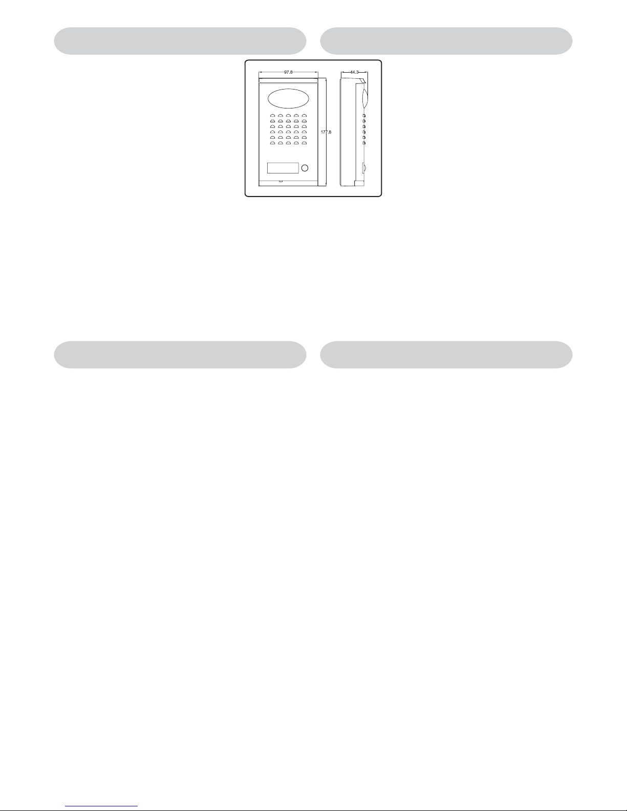
amplificazione audio edil portiere elettrico (dimensioni delposto esterno
come da disegno- quote inmm).
Nr.1 - Videocitofono Bianco& Nero conschermo piatto da4”.
Nr.1 - Trasformatore di alimentazione in contenitore DIN 5
moduli - tipoA. Primario127-230Vac,Secondario 24Vac-1,6A.
La versione a colori prevede l’unità di ripresa al
posto della ed il videocitofono a colori con schermo piatto TFT
, al posto del . La placca frontale del posto esterno è
disponibile in 2finiture: Bianco eGrigio (/W o/G dopo ilcodice).
(rispetto ai precedenti posti
esterni)
La versione con memoria video prevede l’
(videocitofono Bianco & Nero con schermo piatto da 4” e memory board) al
posto del e l’ (alimentatore in contenitore DIN 8 moduli tipo A con doppia tensione di uscita 24Vac 1,6A e 12Vdc 0,2A per
l’alimentazione della memoryboard) al postodell’ .
SMVK1
Art.331K
Art.3351
Art.850K
CSMVK1 Art.331KColour
331K
Art.3451 3351
-
-
-
SMVK1/MV Art.3551
3351 Art.850K/MV
850K
2
SMVK1, SMVK1/MV, CSMVK1 Easy Videokit B&W, con MEMORIA VIDEO, a COLORI
SMVK1, SMVK1/MV, CSMVK1 Easy Videokit B&W, with MEMORY BOARD, COLOUR
ISTRUZIONI PER L’INSTALLAZIONE DEL POSTO ESTERNO
MOUNTING INSTRUCTIONS OF THE OUTDOOR STATION
The new videokit SMVK1 issupplied with the 3000 series
videophone and the new more compact outdoor station
Art.331K. The new outdoor station (Surface mount only)
has been improved in a number of ways for better
endurance to the weather. The mechanism to adjust the
viewing angle has been changed to allow a larger angle
(10 Degree) than before and to allow horizontal and
vertical motionof the camera; This enable an adjustment
to the picture when the outdoor station is installed in
critical areas (areas exposed directly to the sun light,
hidden areas etc.).
The (oneway videokit) iscomprised of:
- Outdoor Station. It incorporates a
high quality auto iris lens CCD camera B&W, LEDs
for infrared illumination (white light LEDs for colour
version), audio amplifiers and one call button (outdoor station size as in
the drawing -unit mm).
- Videophone witha 4” B&W flat screen monitor.
- Power transformer in a type A 5 module DIN box;
primary: 127 and230Vac, secondary 24Vac 1,6A.
SMVK1
Nr.1 Art.331K
Nr.1Art.3351
Nr.1 Art.850K
-
-
-
The uses the (a videophone with a 4” flat screen
monitor B&W plus the memory board) instead of the Art.3351 and the
(Power Supply in a type A 8 module DIN box with 2 output
voltages: 24Vac 1,6A and 12Vdc 0,2A for memory board supply) instead of
the Art.850K.
The uses the (a videophone with a colour 4” TFT flat
monitor) instead of the and the colour outdoor station
instead of the .
The front plate is available in two different finishes: white and grey (put /W or
/G after theproduct code).
SMVK1/MV Art.3551
Art.850K/MV
CSMVK1 Art.3451
Art.3351
Art.331KColour Art.331K
!
!
!
!
!
!
!
!
C
C
C
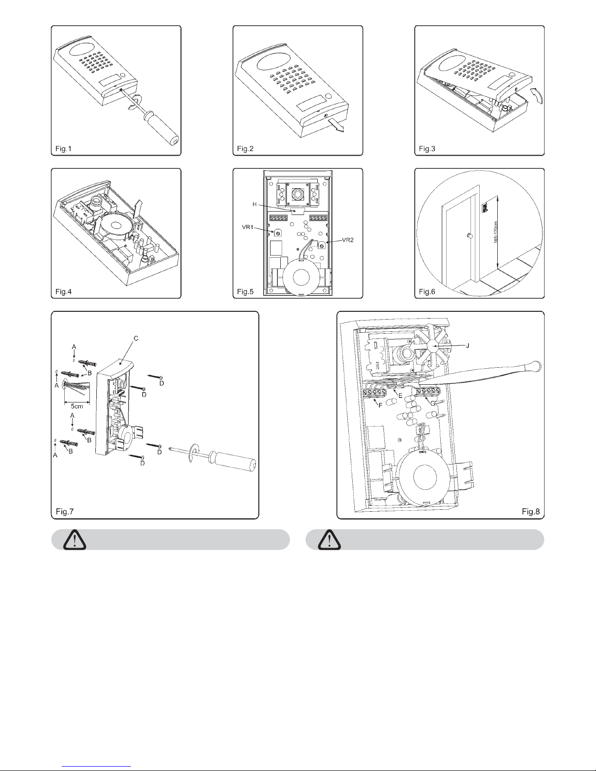
Unscrew the screw at the bottom of the front plate using a Phillips
screwdriver as shownon figure 1.
Gently slide the front platedown (3-4mm) and thenraise it at the bottomas
shown on figures2 and 3.
Extract the speaker housing (leaving the speaker inside it) lifting it up
gently asshown onfigure 4 until the speaker housing is as shown in figure
5 (speaker bracketdown).
Place the outdoor station against the wall(165-170 Cm between the top of
the outdoor station and the floor level as shown on figure 6) and mark the
fixing holes (Ref.A figure 7) for the four wall plugs (Reff.B figure 7) and the
hole for the cables with reference to the relevant opening on the outdoor
station (Ref.H figure 5). For ease of connection, the cables should be at
least 5 cm in length from the wall (see figure 7). If the cables are placed,
mark the holes feeding the wires through the outdoor station opening
(Ref.H figure 5).
Make the four fixing holes (Ref.A figure 7 - 6mm n); put inside the holes
the four wall plugs provided (Ref.B figure 7);place the outdoor station
against thewall feeding the cables through relevant opening (Ref.H figure
5) and then fix it to the wall with the four screws provided using a Phillips
screwdriver.
After the outdoor station is fixed to the wall, make the connections by
putting the cables (Refer figure 8) into the relevant terminals (Refs. F and
G figure 8). The connections must bemade as per the installation diagram
provided. Fix the wires inside the terminals using a terminal screwdriver.
For ease of connection we suggest using tweezers to locate the cables
into the terminals(see figure 8).
After the system test, Refit the outdoor station front plate. Fix the front
plate as follows
Place the front plate over the outdoor station as shown on figure 3
(leaving 3-4mmbetween the top of the plate and the outdoor station)
then move the bottom of the plate in the opposite direct to the arrow
in figure 3bring the platetowards the backbox.
Slide the plateupwards in theopposite direction tofigure 2.
Fix the plateusing the relevantscrew.
After the connections are made, put the speaker back with its bracket (it
should go back as shown on figure 4) then test the system and adjust the
viewing angle moving the camera slightly to the direction required (Ref. J
figure 8).
La realizzazione dell’impianto deve essere eseguita nel rispetto delle vigenti
normative nazionali, inparticolare si raccomandadi:
Collegare l’impianto alla rete elettrica tramite un
che abbia una distanza di separazione del
contatto dialmeno 3mm per ciascun polo e che sia in grado di disconnettere
tutti i polisimultaneamente;
Il deve essere posizionato in un
luogo tale daconsentirne un facileaccesso in casodi necessità.
Rimuovere i coperchi copri-morsetti svitando le relative viti e tirandoli verso
l’alto;
Fissare l’alimentatore su barra DIN o direttamentea pareteutilizzando le viti
ed i relativitasselli ad espansioneforniti a corredo;
Togliere la tensione direte tramiteil dispositivo sopra indicato edeseguire le
connessioni come previsto dagli schemi proposti (la connessione verso la
rete va effettuatain base allatensione disponibile 127o 230Vac).
Verificare che non vi siano errori di connessione e che ifili siano ben serrati
nei morsetti;
Inserire a scattoi coperchi copri-morsettie fissarli tramitele relative viti;
Eseguiti tutti icollegamenti, dare tensioneall’impianto.
·
·
-
-
-
-
-
-
dispositivo di
interruzione omnipolare
dispositivo di interruzione omnipolare
Installazione dell’alimentatore
The system must be installed according to national rules in force, in particular
we recommend to:
Connect the system to the mains through an which
shall have contact separation of at least 3mm in each pole and shall
disconnect all polessimultaneously;
The shall be placed for easy access and the switch
shall remain readilyoperable.
Remove the terminalside covers byunscrewing the retainingscrews;
Fix the power supply to a DIN bar or directly to the wall using two expansion
type screws;
Switch off the mains using the circuit breaker mentioned above and then
make the connectionsas shown onthe installation diagrams;
Check the connectionsand secure thewires into theterminals;
Replace the terminalcovers and fixthem using therelevant screws;
When all connectionsare made, restorethe mains.
·
·
-
-
-
-
-
-
all-pole circuit breaker
all-pole circuit breaker
Power Supply Installation
CONNECTION TO MAINS AND
POWER SUPPLY MOUNTING INSTRUCTIONS
COLLEGAMENTO ALLA RETE ELETTRICA ED
INSTALLAZIONE DELL’ALIMENTATORE
3
A
B
B
B
B
D
E
E
E
E
F
Fig.9
G
H
C
Fig.10
I
L
A
M
F
N
N
N
N
O
Piano terra finito
Finished Floor
Piastra di fissaggio Videocitofono
Mounting Plate
135cm
Quote in cm
Size in cm
Fig.11
A
Mounting plate installation and PCB
connections.
A
fig.11
B
fig.9 C fig.9
D fig.9
C
B
DA
E fig.9
F A fig.9
G-H
F fig.9
fig.10
Installing the Videophone onto mounting plate
fig.10 L
AI
fig.10
M
F
LN
A
O fig.10
O
Notes
!
!
!
!
!
!
!
!
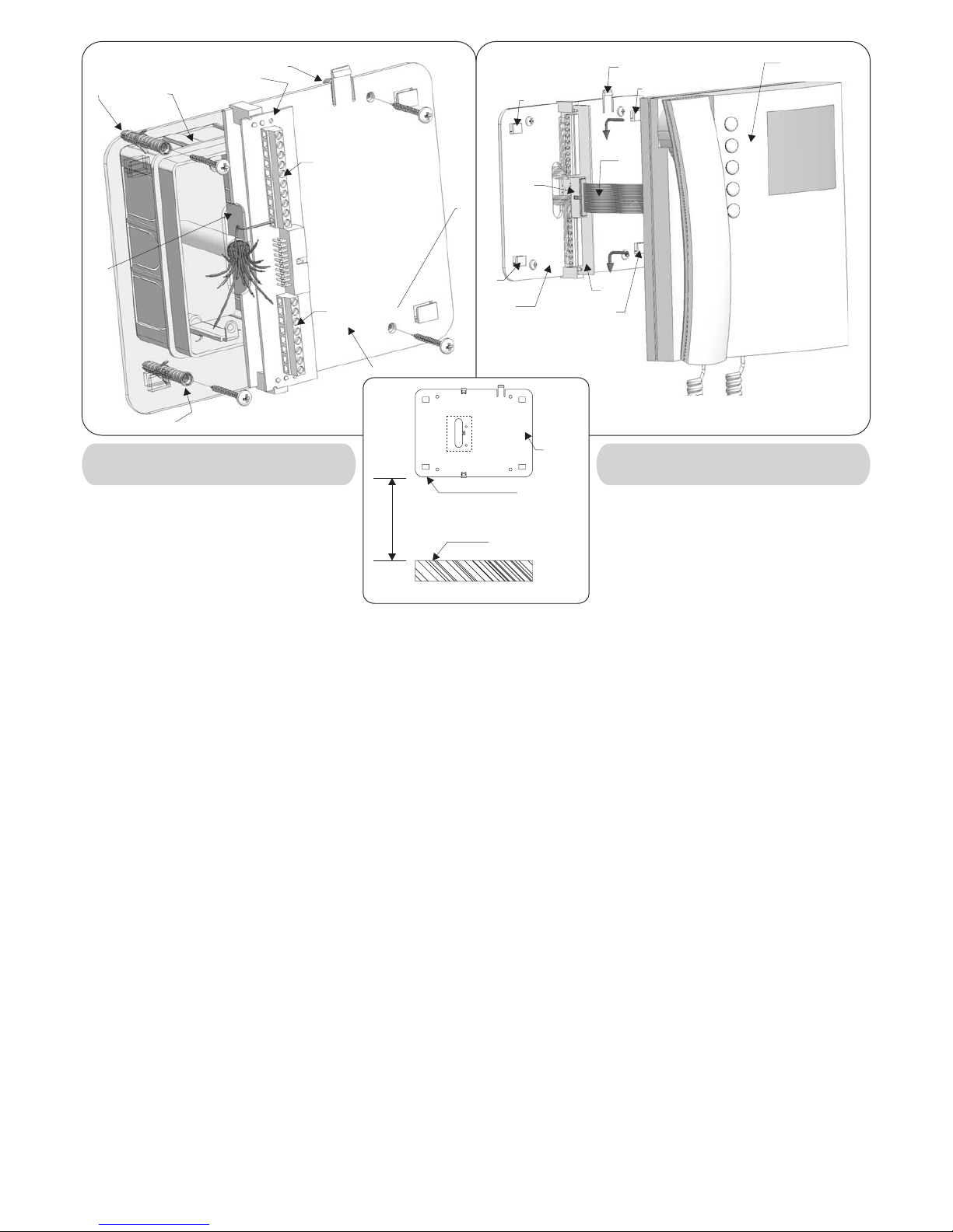
Place the mounting plate against the wall as
shown in (135cm from floor level); and
mark the fixing holes for the four wall plugs
( ) and for the back box if used ( )
which must be flushed into the wall in line with
the opening asshown in .
Once the back box is flushed into thewall (if used), drill the four
fixing holes and insert the wall plugs . Thread the cables through
the opening and fix the mounting plate to the wall with the 4
screws ( ), using a Philips screwdriver.
Fit the PCB against the mounting plate as shownin ; insert
the wires (As short as possible) into terminals . Secure them
using a terminal screwdriver.
Unclip the PCB ( ), rotate it 90º anticlockwise and fit it into its
housing as shown in .
As shown in , move the videophone close to the mounting
plate so thatthe ribbon cable will reach the connector .
As shown in , connect the female plug on the ribbon cable I
coming from the videophone to the male plug connector on the
PCB .
Place the videophone against the 4 hooks on the mounting
plate and push down: the videophone will automatically lock into
place using clasp as shown in .
To remove the videophone from the wall, push the clasp in the
direction of the wall with a screwdriver and at the same time push
the videophone upwards.
We recommend using a back box in order to contain excess wire
behind the back plate.
The wires must be connected to the terminals as shown on the
relevant wiring diagrams.
(1)
(2)
(1)
(2)
Applicazione a muro della piastra di
fissaggio e collegamenti scheda di
connessione.
A
fig.11
B
fig.9
C fig.9
D fig.9
C
B
D A E fig.9
FA
fig.9
GH
F fig.9
fig.10
Applicazione del Videocitofono alla piastra
fig.10 L A
I
fig.10 I
MF
LNA
fig.10
O
Note
!
!
!
!
!
!
!
!
Appoggiare al muro la piastra di fissaggio
come indicato in (135cm da terra);
prendere i riferimenti dei quattro fori per
l’inserimento dei 4 tasselli ad espansione
( ) e, nel caso si impieghi, prendere il
riferimento per la scatola da incasso ( ),
che dovrà essere murata in posizione centrale rispetto all’apertura
, al finedi agevolare il passaggiodei fili come mostratoin .
Murare (se impiegata) la scatola da incasso , eseguire i 4 fori
ed inserire i tasselli ad espansione . Passare i cavi nell’apertura
e fissare la piastra con le 4 viti ( ), utilizzando un
cacciavite a croce.
Appoggiare la scheda di connessione sulla piastra come
mostrato in ; inserire i fili (che devono essere più corti
possibile) nelle morsettiere ed e serrare con un cacciavite a
taglio.
Fissati i fili, sfilare la scheda di connessione ( ), ruotarla di
90º in senso antiorario ed infilarla nella propria sede come
mostrato i n .
Avvicinare, come da , il videocitofono alla piastra per
agevolare la connessionedel flat .
Come mostrato in inserire il connettore del flat , che
fuoriesce dalla parte posteriore del videocitofono, nel connettore
della scheda diconnessione .
Facendo corrispondere le 4 fessure presenti sulla base del
videocitofono con i 4 incastri della piastra , appoggiare il
video sulla piastra e spingerlo verso il basso fino allo scatto,
compiendo un movimentocome mostrato dalle freccein .
Per rimuovere il videocitofono, spingere con un cacciavite a taglio
il dente verso il muro e, contemporaneamente, tirare il
videocitofono verso l’alto.
Si consiglia di utilizzare unascatola da incasso (non in dotazionee
reperibile sul mercato) al fine di contenere l’eventuale lunghezza
eccedente dei fili.
I collegamenti alla morsettiera devono essere eseguiti rispettando
gli schemi forniti a corredo del videocitofono (per applicazioni
differenti da quelle degli schemi standard, rivolgersi al proprio
rivenditore).
(1)
(2)
(1)
(2)
4
Art.3351, 3451, 3551
Videophones Mounting Instructions
Istruzioni di montaggio per
i Videocitofoni Art.3351, 3451 e 3551
 Loading...