

Page 1

66221130-EN - V3.0 - 12/09/14
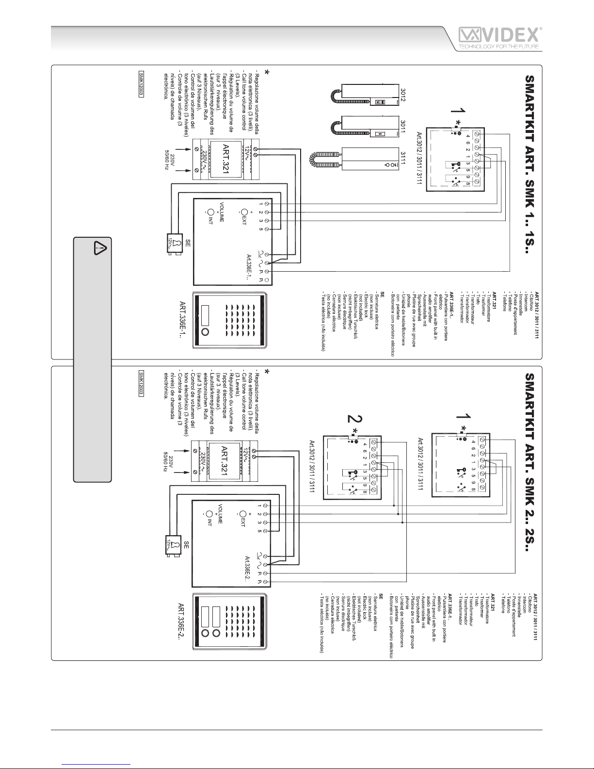
Art.SMK/N - SMK/3012 - SMK/3111 - Installation instructions
Smart Series Audiokit
C
T
C
C
C
A
B
F
E
D
G
Fig. 1 - Flush mounting outdoor station
I
I
A
H
H
B
C
C
C
C
E
F
G
D
T
Fig. 2 - Surface mounting outdoor station
OUTDOOR STATION MOUNTING INSTRUCTIONS
FLUSH MOUNTING OUTDOOR STATION ART.SMK1 SMK2 FIG. 1
• Fix the intercom to the wall by using the two expansion type screws provided;
• Fix the transformer on a DIN bar or directly to the wall by using the two expansion type screws provided;
• Remove front plate (F) and PCB holder (B);
• Mount the back box (A) at the designated height, ensuring the arrow is pointing to the top, with the cables threaded through it.
Ensure that all xing holes are cleanly andaccurately nished;
• Thread the cables through the relevant opening (D) of the PCB holder (B) then x it to back box (A) by using the 4 screws (C) provided;
• Carry out connections accurately using wiring diagram provided;
• Switch power on and check system is working correctly: speech and door opening, after making a call from the outdoor station
which is con rmed by a tone from the outdoor station loudspeaker. The audio ampli ers are pre-adjusted for a good level of
speech, however, if required, it is possible to adjust EXTVOLUME and INTVOLUME by altering the trimmers (T) to avoid the
Larsen eff ect (feedback) when front plate (F) has been mounted;
• Screw the xing nut (E) leaving the hole in a vertical position and then t the front plate (F) in the upper part of PCB holder (B)
and x the lower part by using the screw (G).
SURFACE MOUNTING OUTDOOR STATION ART.SMK1S SMK2S FIG. 2
Follow instructions above changing the fourth point as follow:
• Fix the surface mounting box (A) to the wall by using the 2 expansion screws provided (H).
Note: To reset the thermal fuse in the transformer after a short circuit or other fault, switch off the power to the transformer and
remove the source of the short circuit. Restore power after approximately 60seconds and check for correct output voltage.
CONNECTION TO MAINS AND POWER SUPPLY MOUNTING INSTRUCTIONS
The system must be installed according to national rules in force, in particular we recommend to:
• Connect the system to the mains through an all-pole circuit breaker which shall have contact separation of at least 3mm in
each pole and shall disconnect all poles simultaneously;
• The all-pole circuit breaker shall be placed for easy access and the switch shall remain readily operable.
POWER SUPPLY INSTALLATION
• Remove the terminal side covers by unscrewing the retaining screws;
• Fix the power supply to a DIN bar or directly to the wall using two expansion type screws;
• Switch off the mains using the circuit breaker mentioned above and then make the connections as shown on the installation
diagrams;
• Check the connections and secure the wires into the terminals;
• Replace the terminal covers and x them using the relevant screws;
• When all connections are made, restore the mains.
Smart Kit SMK/N - SMK/3012 - SMK/3111 Audiokit
Page 2
66221130-EN - V3.0 - 12/09/14
Art.SMK/N - SMK/3012 - SMK/3111 - Installation instructions
Smart Series Audiokit
WE RECOMEND
This equipment is installed by a Competent Electrician,
Security on Communications Engineer
Smart Kit SMK/N - SMK/3012 - SMK/3111 Audiokit
Page 3

66221130-EN - V1.0 - 11/09/14
3
Art.SMK/N - SMK/3012 - SMK/3111 - Installation instructions
Smart Series Audiokit
Wiring Guide Line
All intercoms wiring must run separately from the mains cable.
The cable type should be CW1308 or an equivalent cable. The cable size should comply with the table below.
DISTANCE METERS CABLE SIZE MM2
50 0.35
100 0.5
200 0.75
300 1.0
400 1.5
Max resistance of all lines: 8 Ohm
Before powering the system up, the wiring should be double checked to ensure it complies with the wiring diagram supplied.
TROUBLE SHOOTING GUIDE
In the event of the system not functioning correctly when you power up, the following points can be checked (a multimeter will be
needed).
SYSTEM DEAD
• Check mains input to the transformer.
• Check the 12Vdc (+12 terminal) output from the power supply.
• Check fuses.
• Check for shorts on power supply wires.
SPEECH & LOCK WORKS BUT NO ELECTRONIC CALL TONE
• Check the link between “C” and “C1” terminals of the speaker unit.
• Call wire to terminal “4” of the handset broken on in short circuit; check the walk of the call wire.
NO SPEECH FROM THE DOOR PANEL
• Check and/or adjust the volume operating on trimmers controls on rear of speaker unit.
• Check the wire from terminal “2” of the speaker unit to terminal “2” of the handset.
NO SPEECH FROM THE HANDSET
• Check and/or adjust the volume operating on trimmers controls on rear of speaker unit.
• Check the wire from terminal “1” of the speaker unit to terminal “1” of the handset.
LOCK DOES NOT WORK
• Check on the handset the link between terminals “1” and “5”.
• Check the 13Vac output on the transformer.
• Check the wires of the electric lock.
• Wires section not in conformity with the table above.
FEEDBACK PROBLEM LARSEN EFFECT
• Check that the handset microphone is rmly tted inside its housing.
• Check that the speaker unit microphone is rmly tted inside its housing and nothing is obstructing the microphone hole.
• Adjust the volume operating on trimmer controls on rear of the speaker unit.
HUM ON THE SPEECH LINES
• Check that system cables are not running close to any high voltage or mains cables.
• Check that the system is wired exactly as shown on the wiring diagram.
WE RECOMMEND THIS EQUIPMENT IS INSTALLED BY A COMPETENT ELECTRICIAN, SECURITY OR COMMUNICA
TIONS ENGINEER.
If further assistance is required, call the technical help desk on 0191-2243174 for uk customers or +39 0734631669
for other countries.
Page 4

COSTUMER SUPPORT
All Countries:
VIDEX ELECTRONICS S.P.A.
www.videx.it - technical@videx.it
Tel: +39 0734-631669
Fax: +39 0734-632475
UK Customers:
VIDEX SECURITY LTD
www.videx-security.com
Tech Line: 0191 224 3174
Fax: 0191 224 1559
The product is CE marked demonstrating its conformity and is for distribution within all member states of the EU with no restrictions. This product
follows the provisions of the European Directives 2004/108/ECC (EMC);
2006/95/ECC (LVD) and 93/68/ECC (CE marking).
Main UK oce:
VIDEX SECURITY LTD
1 Osprey Trinity Park
Trinity Way
LONDON E4 8TD
Phone: (+44) 0870 300 1240
Fax: (+44) 020 8523 5825
www.videx-security.com
marketing@videx-security.com
Northern UK oce:
VIDEX SECURITY LTD
Unit 4-7
Chillingham Industrial Estate
Chapman Street
NEWCASTLE UPON TYNE - NE6 2XX
Tech Line: (+44) 0191 224 3174
Phone: (+44) 0870 300 1240
Fax: (+44) 0191 224 1559
Greece oce:
VIDEX HELLAS Electronics
48 Filolaou Str.
11633 ATHENS
Phone: (+30) 210 7521028
(+30) 210 7521998
Fax: (+30) 210 7560712
www.videx.gr
videx@videx.gr
Danish oce:
VIDEX DANMARK
Hammershusgade 15
DK-2100 COPENHAGEN
Phone: (+45) 39 29 80 00
Fax: (+45) 39 27 77 75
www.videx.dk
videx@videx.dk
Benelux oce:
VIDEX BENELUX
E3 Iaan, 93
B-9800 DEINZE
Phone: (+32) 9 380 40 20
Fax: (+32) 9 380 40 25
www.videxbenelux.be
info@videxbenelux.be
VIDEX ELECTRONICS S.P.A.
Via del Lavoro, 1 - 63846 Monte Giberto (FM) Italy
Tel (+39) 0734 631669 - Fax (+39) 0734 632475
www.videx.it - info@videx.it
 Loading...