

Page 1
66250905-EN - V1.0 - 06/02/14
1
Kristallo Series
Art.KRV98-KRV96 - Installation instructions
112 42
155
182
29
LAN
+12Vdc
GND
Made in Italy
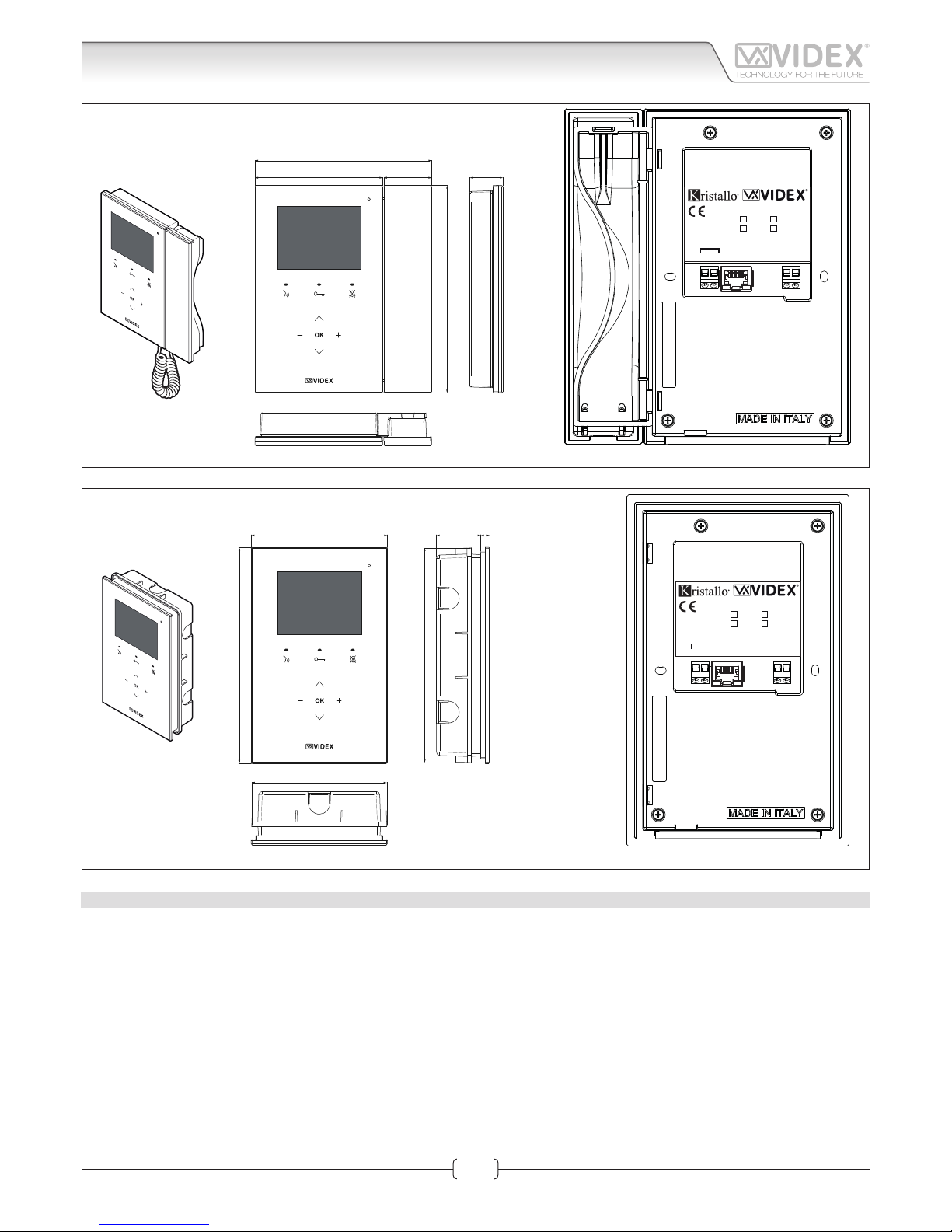
KRV98
KRV96
/W (white)
/B (black)
H
L
CAN BUS
Fig. 1 KRV96
120
190
839
189
119
LAN
+12Vdc
GND
Made in Italy
KRV98
KRV96
/W (white)
/B (black)
H
L
CAN BUS
Fig. 2 KRV98
DESCRIPTION
• Kristallo design with touch sensitive buttons;
• 3.5” LCD TFT High Denition Display
• Available in a ush mounting (handsfree) version or surface mount version with handset (for handsfree or conventional). A desk
mount kit is available for the surface with handset version,
• 10/100 Mbit Ethernet interface;
• PoE or 12Vdc power supply;
• Compatible with the SIP protocol (it can be connected with VOIP switchboard systems);
• Built in web server to set operation parameters;
• Firmware can be updated through a web server;
• Self search function and self setting of Videx IP devices connected on the same network;
• Integrated picture memory facility with automatic capture;
• Privacy function with programmable activation time from 30 min to 24 h or unlimited;
• History of events;
Art.KRV98-KRV96 3.5" IP Videointercom
Connection
Page 2
66250905-EN - V1.0 - 06/02/14
2
Kristallo Series
Art.KRV98-KRV96 - Installation instructions
• Intercommunication with other devices of the system (outdoor stations, videophones, tablet or PC with client installed) user can
be selected through a complete contacts list or through “favorites” (communication with outdoor stations is audio/video and it’s
possible to activate the relays);
• It is possible to activate the relays of the outdoor stations through a menu option;
• “Weather forecast” function through google weather service (an internet connection to the network is required);
• Melody and desktop can be customized by loading audio les and pictures.
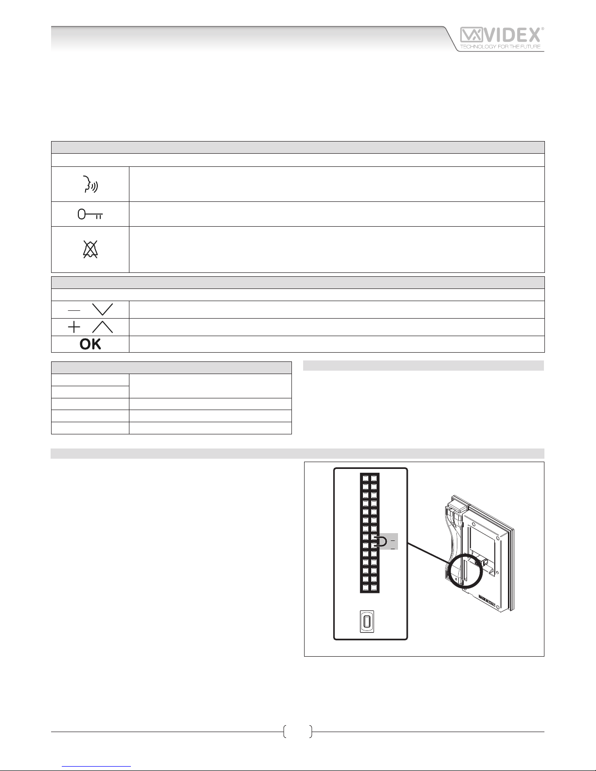
BUTTONS OPERATION IN STANDBY MODE
With the video intercom in stand-by and the monitor switched o, press any button to switch on.
RAPID CALL BUTTON
By pressing this button you access directly into the “rapid call” submenu. If the list includes one contact only
the call starts directly.
LOCKS
By pressing this button you access directly into the “locks” menu (See LOCKS paragraph in Graphic Interface section).
PRIVACY FUNCTION
By pressing this button you enable the privacy service (the relevant LED switches on) and the videointercom
receives incoming calls but doesn’t switch on the audio or the video connection.
The service is disabled by the privacy time expiring or by pressing the same button again.
MENU NAVIGATION BUTTON
If the videointercom is in stand-by but the monitor is switched o, rst press any button to switch on the display.
or
With the videointercom in stand by and switched on it selects the previous menu icon
or
With the videointercom in stand by and switched on it selects the next menu icon
With the videointercom in stand by and switched on it enters in the currently selected menu icon
TERMINALS
L
Not used
H
LAN 10/100Mb Ethernet Interface RJ45 plug
+12Vdc 12Vdc - 500mA Power Supply Input
0Vdc Ground
TECHNICAL SPECIFICATION
• Power supply voltage: 12Vdc
• Power consumption: 500mA max
• Working temperature: -10° +50° C
IP VIDEOINTERCOM RESTORE TO FACTORY PRESET
To restore the settings to the factory preset proceed as follows:
1. Power down the video intercom (disconnect the power supply connector or in case of POE switch/router disconnect the
Ethernet cable);
2. On the rear side of the video intercom, on the 28 way connector, put in short the two terminals as shown in Fig. 3;
3. Power on the video intercom and wait for the boot;
4. Remove the link when the video intercom emits an acoustic signal;
5. Once the boot is complete the video intercom is ready to work;
The video intercom settings are restored to the following:
Network Parameters
IP Address: 192.168.1.4
Net Mask: 255.255.255.0
Gateway: 192.168.1.1
DNS Server: 8.8.8.8
Login Credentials
Username: admin
Password: admin
Advanced Setup Password
Password: 0000
14
13
12
11
10
9
8
7
6
5
4
3
2
1
28
27
26
25
24
23
22
21
20
19
18
17
16
15
RESET
BUTTON
Fig. 3
Art.KRV98-KRV96 3.5" IP Videointercom
Connection
Page 3
66250905-EN - V1.0 - 06/02/14
3
Kristallo Series
Art.KRV98-KRV96 - Installation instructions
IP VIDEO INTERCOM MANUAL RESET
In case the system locks (touch sensitive buttons not recognized) you can reset manually the video intercom:
1. On the rear side of the video intercom, under the 28 way connector there is a small button see Fig. 3;
2. Using a thickness tool, press shortly the button and wait for the video intercom reboot;
3. Once the boot is complete the video intercom is ready to work;
This procedure reboots only the video intercom without aect any setting.
POWER SUPPLY & CONNECTION
In case of POE (Power Over Ethernet) Switch/Router, follow the connection shown in Fig. 4 otherwise, in case of standard Switch/
Router, follow the connection shown in gure Fig. 5.
LAN
+12Vdc
GND
Made in Italy
KRV98
KRV96
/W (white)
/B (black)
H
L
CAN BUS
LAN
+12Vdc
GND
Made in Italy
KRV98
KRV96
/W (white)
/B (black)
H
L
CAN BUS
Connect to a POE (Power Over
Ethernet) Switch or Router
Connect to a POE (Power Over
Ethernet) Switch or Router
Fig. 4
LAN
+12Vdc
GND
Made in Italy
KRV98
KRV96
/W (white)
/B (black)
H
L
CAN BUS
LAN
+12Vdc
GND
Made in Italy
KRV98
KRV96
/W (white)
/B (black)
H
L
CAN BUS
230V
12Vdc
Art.AMR2-12
or
12Vdc 2A
PSU
230V
12Vdc
Art.AMR2-12
or
12Vdc 2A
PSU
Connect to a Switch,
Router or directly** to the
ethernet interface of the
Art.4503
Connect to door panel's
power supply unit*
Connect to a Switch,
Router or directly** to the
ethernet interface of the
Art.4503
Connect to door panel's
power supply unit*
To Art.4503
To Art.4503
Fig. 5
* When the devices are connected directly certain features which require the internet will not be available.
** If the videointercom is not connected to a POE switch or router, it is necessary to connect an external PSU (terminals “+12Vdc” & “GND”). If the videointercom is provided in a video kit, you can use
the PSU included in the video kit. For distances between the videointercom and the PSU up to 25 metres use 2 cables 1.0mm2 (AWG17).
Connection
Art.KRV98-KRV96 3.5" IP Videointercom
Page 4
66250905-EN - V1.0 - 06/02/14
4
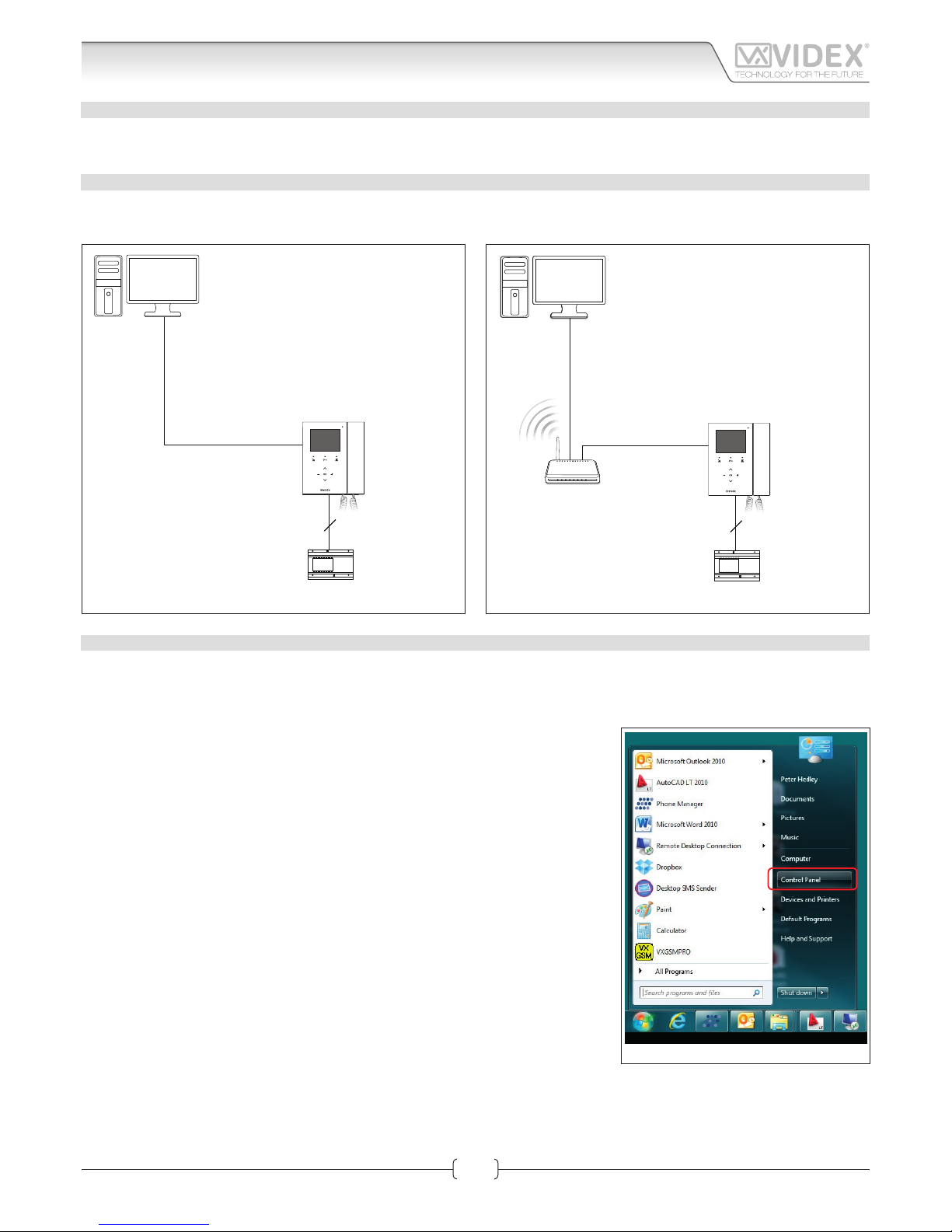
HARDWARE SETUP WITH CROSSOVER CABLE
Power up the Art.KRV98/96 and connect a crossover cable between the PC/Laptops network connection and the Art.KRV98/96
network connection (TCP/IP) as shown in Fig. 1.
HARDWARE SET UP WITH SWITCH AND PATCH CABLE
Power up the Art.KRV98/96 and connect a patch cable between the Art.KRV98/96 network connection (TCP/IP) and the Switch and
then connect a patch Ethernet cable between the PC/Laptops network connection and the Switch as shown in Fig. 2.
2
AMR2-12
12Vdc Power supply
Crossover cable
PC/Laptop
Art.KRV96/98
IP videophone
Fig. 1
2
Standard or
Wi-Fi Router
AMR2-12
12Vdc Power supply
Patch
Ethernet cable
Patch
Ethernet cable
PC/Laptop
Art.KRV96/98
IP videophone
Fig. 2
HARDWARE SET UP NOTES
These rst steps simply put your PC/laptop into the same IP range as the default Art.KRV98/96. There are many ways to reach the
“Local area connections” window depending on your windows set up. These steps present one of them (also see appendix for Windows Vista/Windows 2000/XP).
First click on the start menus Windows icon in the bottom left of the screen and select
“Control Panel” from the list on the right hand-side as shown in Fig. 3.
Fig. 3
Art.KRV98-KRV96 Hardware setup
Kristallo Series
Art.KRV98-KRV96 - Installation instructions
Page 5
66250905-EN - V1.0 - 06/02/14
5
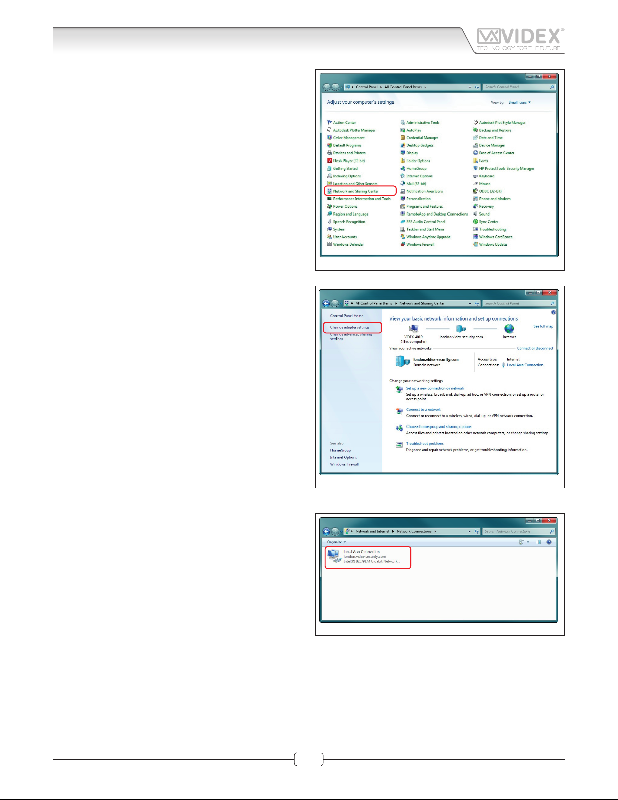
The “Control Panel” window shown in Fig. 4 will appear. Click on
“Network and Sharing Center” option.
The window shown in Fig. 5 will appear. Select “Change adaptor
settings” option on the left hand-side.
The window shown in Fig. 6 will appear. Double click on the “Local Area Connection” icon.
Fig. 4
Fig. 5
Fig. 6
Art.KRV98-KRV96 Hardware setup
Kristallo Series
Art.KRV98-KRV96 - Installation instructions
Page 6
66250905-EN - V1.0 - 06/02/14
6
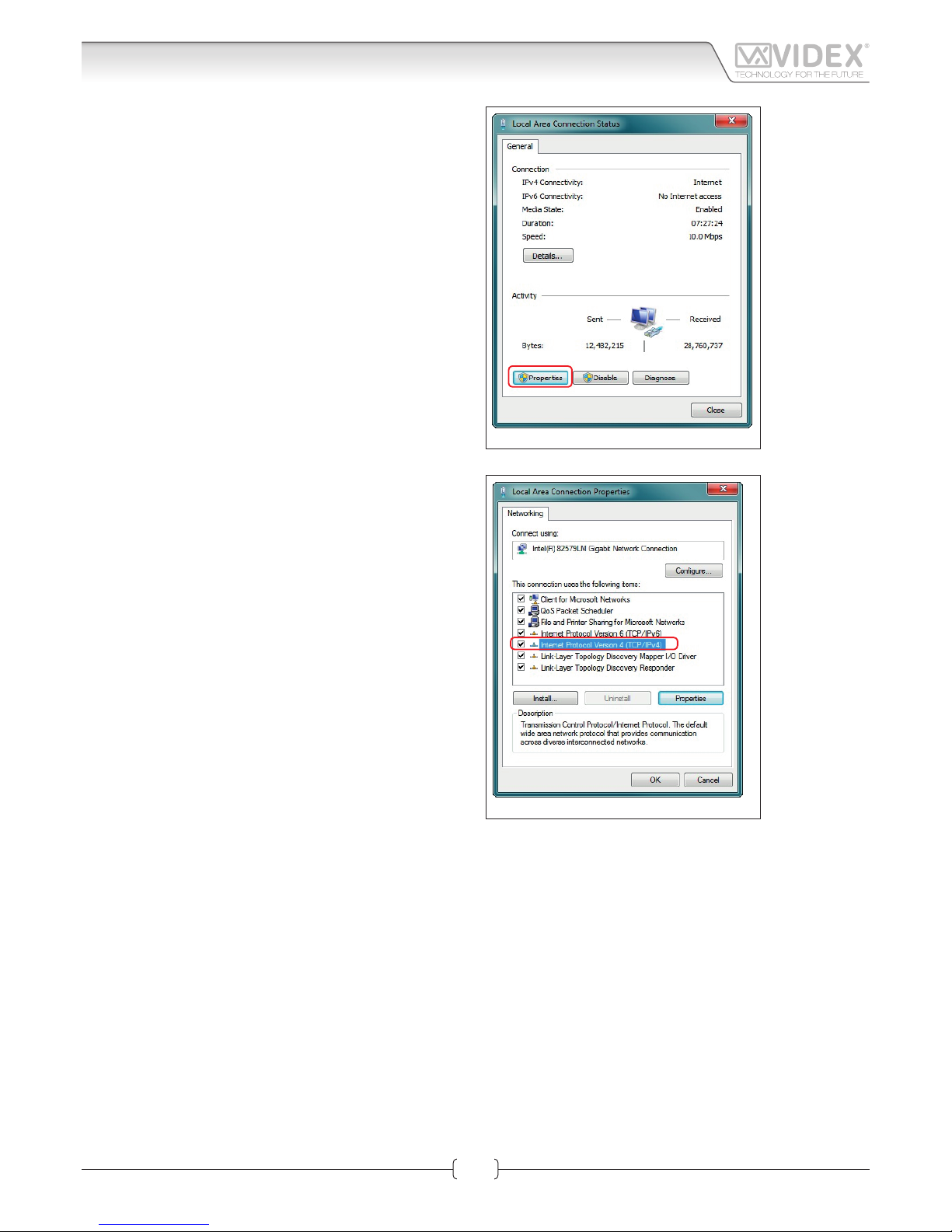
The “Local Area Connection Status” window shown in Fig. 7 will
appear. Click on the “Properties” button.
The “Local Area Connection Properties” window shown in Fig.
8 will appear. Highlight “Internet Protocol Version 4 (TCP/IPv4)”
from the list then click on the “Properties” button.
Fig. 7
Fig. 8
Art.KRV98-KRV96 Hardware setup
Kristallo Series
Art.KRV98-KRV96 - Installation instructions
Page 7
66250905-EN - V1.0 - 06/02/14
7
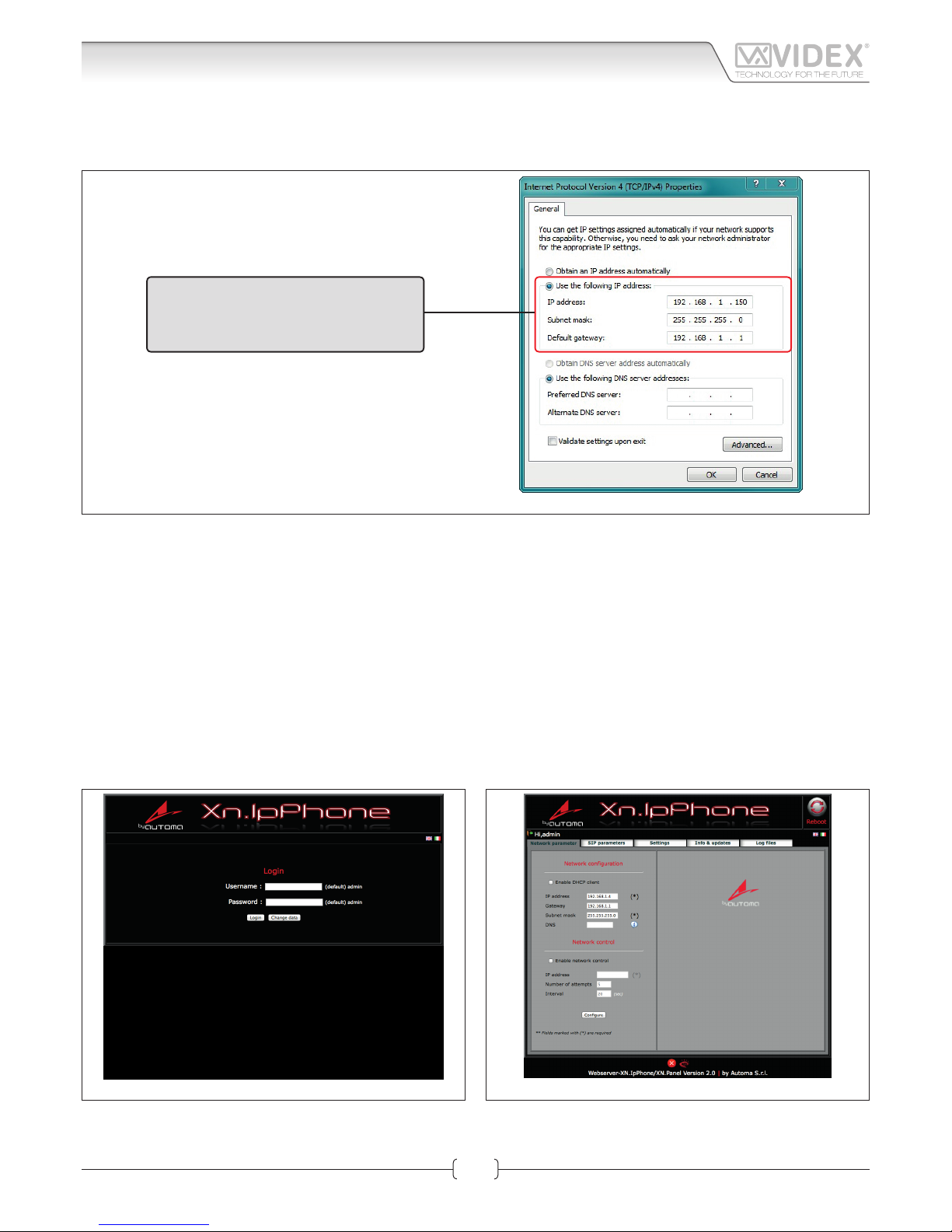
The “Internet Protocol Version 4 (TCP/IPv4) Properties” window shown in Fig. 9 will appear. Before changing settings in this window
rst make a note of the current IP Address, Subnet mask and default gateway settings as you will need to restore them once the task
is complete. Select “Use the following IP address:” and complete the following details as highlighted.
Use the following IP address:
IP address: 192.168.1.150
Subnet mask: 255.255.255.0
Default gateway: 192.168.1.1
Fig. 9
IMPORTANT NOTE!
The default IP address of the Art.KRV98/96 is preset as “192.168.1.4”. When entering the information in the “Internet Protocol Version 4 (TCP/IPv4) Properties” window (as shown above) the IP address that is entered must be within the same range
as the default IP address “192.168.1.4” in this example we are using “192.168.1.150”. The range of IP addresses can be between 1 to 255. Only the last set of digits of the IP address needs to be changed “192.168.1.n” where n = 1 to 255.
After completing the details (as shown above) click on “OK” and close all windows and exit “Control Panel”.
Your PC/laptop is now ready to change the Art.KRV98/96 default IP address to one suitable for your network.
Repeat these steps later to restore your PC/laptop back to its original settings.
Next click on the internet browser icon on your desktop and enter the following web address “http://192.168.1.4/” as shown then press enter.
NETWORK PARAMETERS CHANGES
Fig. 10 Fig. 11
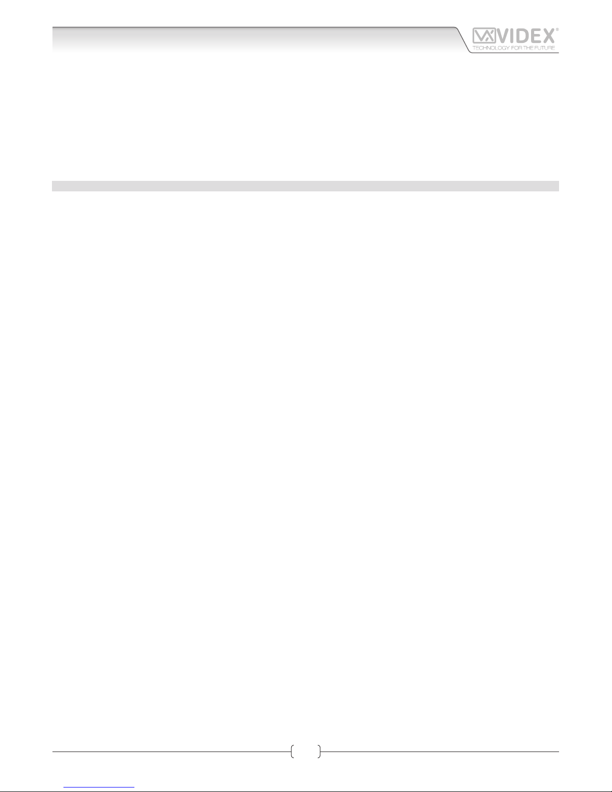
The “LOGIN” web page shown on Fig. 10 should appear. Enter the default Username (in lower case) and Password then click on the
“Login” button.
Art.KRV98-KRV96 Hardware setup
Kristallo Series
Art.KRV98-KRV96 - Installation instructions
Page 8
66250905-EN - V1.0 - 06/02/14
8
The “Art.KRV98/96 Network Parameters” web page should appear as shown in Fig. 11.
The IP Address, SubnetMask and Gateway IP can now be changed. This information can be obtained from the network administrator.
Once all details have been updated on the “Art.KRV98/96 Network Parameters” web page press the “Congure” button followed by
“Apply conguration”.
IMPORTANT NOTE!
Once you change the IP address you may not be able to connect using the PC/Laptop without repeating the previous steps
to make the PC/Laptop part of the same subnet as the device.
APPENDIX
WINDOWS VISTA
1. Open the start menu from the Windows icon in the bottom left of the screen and select “control panel” from the list on the right
hand-side.
2. Select the option “View network status and tasks”.
3. Select “Manage network connections”.
4. Double click on “Local Area Connection”.
5. Select the button “Properties” at the bottom of the window.
6. Select “Internet Protocol Version 4 (TCP/IPv4)” from the list, then select “Properties”.
7. Before changing any settings in this window rst make a note of the current IP Address, Subnet mask and default gateway settings as you will need to restore them once the task is complete.
8. Complete the information as described on page 6.
9. After completing the details click on “OK” and close all windows and exit “control panel”.
10. Your PC/Laptop is now ready to change the Art.KRV98/96 default IP address to one suitable for your network.
11. Follow the steps as described on section “Network parameters changes” on page 7 to change the IP address of the Art.
KRV98/96.
WINDOWS 2000/XP
1. Open the start menu from the Windows icon in the bottom left of the screen and select “control panel”.
2. In the “control panel” window double-click on the “Network and Dial-Up” connections icon.
3. Click on “Local Area Connection” to bring up a “local area network status” window.
4. In the “components checked are used by this connection” area, highlight “Internet Protocol (TCP/IP)” and click on the “Properties”
button.
5. The Internet Protocol (TCP/IP) properties window will appear.
6. Before changing any settings in this window rst make a note of the current IP Address, Subnet
7. mask and default gateway settings as you will need to restore them once the task is complete.
8. Complete the information as described on page 6.
9. After completing the details click on “OK” and close all windows and exit “control panel”.
10. Your PC/Laptop is now ready to change the Art.KRV98/96 default IP address to one suitable for your network.
11. Follow the steps as described on section “Network parameters changes” on page 7 to change the IP address of the Art.
KRV98/96.
Art.KRV98-KRV96 Hardware setup
Kristallo Series
Art.KRV98-KRV96 - Installation instructions
Page 9

66250905-EN - V1.0 - 06/02/14
9
Kristallo Series
Art.KRV98-KRV96 - Installation instructions
LOGIN
It is recommended that this device is installed by an engineer
with an understanding of Ethernet installations and TCP/IP
protocols. In the case of installations using existing networks it
maybe necessary to request information from the network administrator.
More than one unit can be installed on a system. Each unit must
have a unique IP address which is not currently in use on that
network.
The default network parameters are:
• Static IP Address: 192.168.1.4*
• Subnet mask: 255.255.255.0
• User Name: admin
• Password: admin
* If the videointercom is provided in a two way videokit the default ip address for the “videointercom 1” is “192.168.1.4” while for
the “videointercom 2” is “192.168.1.5”.
If the default IP address on the device is free and in range with your network then, from a PC, tablet or smartphone connected to
the same network, open a browser and enter the URL “http://192.168.1.4”.
Alternatively if the default IP address is not compatible with your network it will be necessary to change this rst. A guide to this
can be found under the “Art.KRV98-KRV96 Hardware setup” section on page 4. The internal webserver will show the login page
of Fig. 1
Enter the user name and password then start to setup the IP Videointercom through the dierent tabs.
In case of problems or mistakes, the videointercom can be restored to the factory preset following the procedure described in the
“IP videointercom restore to factory preset” section on page 2
NETWORK PARAMETERS
This tab allows the editing of all network parameters Fig. 2.
NETWORK CONFIGURATION
“Enable DHCP Client” allows the unit to obtain a dynamic IP address from the network. It is better to leave it disabled and use
a xed IP address.
Edit the elds of the subsection “Network conguration” (Refer
“Network conguration” sections on page 19 and 13 of this
manual) according to the network requirements then press the
“Congure” button followed by “Apply conguration”.
A short countdown signals that the device is updating the
changes.
NETWORK CONTROL
“Enable Check Alive” enables the device to constantly check the
ethernet connectivity.
When this option is set, the module will repeatedly check connection with the IP address entered and if connection is lost will
force a reboot of the unit. If you enable this setting you must set
the IP address to ping, the number of connection attempts and
the time interval between the attempts. Enable this function
when network connection problems could exist.
After changing this setting, press then the “Congure” button followed by “Apply conguration”.
A short countdown signals that the device is updating the changes.
Fig. 1 Login
Fig. 2 Network Parameters
Art.KRV98-KRV96 3.5" IP Videointercom
Web Server
Page 10

66250905-EN - V1.0 - 06/02/14
10
Kristallo Series
Art.KRV98-KRV96 - Installation instructions
SIP PARAMETERS
In this section it is possible the enable SIP server communication (Fig. 3).
The use of the module in combination with a SIP server is an additional feature, if you are not using the IP speaker unit module
with a SIP server you don’t need to set the relevant elds.
For the correct setup of the “SIP SERVER CONNECTION” elds, it
is necessary to know the specic parameters of the SIP server to
which you are connecting the device.
Note: You need to press the edit button if you are changing previously stored settings.
If you are using a simplied SIP registration ( “setup advanced
logging” unchecked) the following parameters are requested:
• Username: it is the username used during the SIP account/
extension generation on the SIP server.
• Password: it is the password for the username above used
during the SIP account/extension generation on the SIP
server.
• Server/Outbound proxy: is the server machine with name of
DNS:port or IP:port
• Realm server: is the SIP protocol used
If you check “setup advanced logging” the following additional
parameters are required:
• Extension: it is the numeric extension code generated on
the SIP server for the username above.
• Domain: it is the domain of the service where you will try
to register with. It can be an IP address or a fully qualied
domain.
After completing the SIP server connection elds remember to
check the “Enable registration to server”.
Press the “Congure” button followed by “Apply conguration”.
A short countdown signals that the device is updating the
changes.
If the setup is correct, after a while, the “Registration Status” indicator should switch from RED to GREEN.
SETTINGS
This tab has 3 subsections:
• "Weather" (Fig. 4) to set the weather services;
• "General settings" (Fig. 5) to set language and monitor backlight options;
• "Modify Password" (Fig. 6 to set the password required for
the advanced settings;
WEATHER
If an internet connection is available on the network, it is possible to enable the weather forecast service through Google
Weather. The videointercom will show the weather forecast for
the selected area.
• Check "Enable weather forecast" to enable the service;
• Complete "Enter a location" eld entering the name of the
location. While entering the name, the system will suggest
the possible cities. This setup also aects the automatic date
& time correction.
Press the “Congure” button followed by “Apply conguration”.
A short countdown signals that the device is updating the
changes.
Fig. 3 SIP parameters
Red
Registration to SIP server not enabled
Gray
Registration to SIP server enabled but the
status is still not recognized
Orange
Registration to SIP server enabled but the
server has still not conrmed the registration
Green
Registration to SIP server enabled and the
server has conrmed the registration.
Fig. 4 Settings - Weather
Art.KRV98-KRV96 3.5" IP Videointercom
Web Server
Page 11

66250905-EN - V1.0 - 06/02/14
11
Kristallo Series
Art.KRV98-KRV96 - Installation instructions
GENERAL SETTINGS
• Language: set the language to be used in the user graphic
interface of the videointercom, click on the eld then select
the required language from the listbox.
• Backlight duration: it is the time in seconds before which
the display goes into energy saving mode. In energy saving
mode the display is switched o.
Press the “Congure” button followed by “Apply conguration”.
A short countdown signals that the device is updating the
changes.
MODIFY PASSWORD
The password that you can modify in this tab is the protection
password required to access the advanced settings from the
graphical interface of the videointercom. It is a numeric code
composed of 4 digits. The default password is 0000.
• Old Password: Enter the old password ;
• New Password: Enter the new password;
• Conrm new password: Repeat the new password.
Press the “Congure” button followed by “Apply conguration”.
A short countdown signals that the device is updating the
changes.
Fig. 5 General Settings
Fig. 6 Modify Password
Art.KRV98-KRV96 3.5" IP Videointercom
Web Server
Page 12

66250905-EN - V1.0 - 06/02/14
12
Kristallo Series
Art.KRV98-KRV96 - Installation instructions
INFO & UPDATES
This tab (Fig. 7) provides information about the rmware version, allows rmware updates and to upload les to be used for
melody or as the background picture.
UPLOAD FIRMARE
Under this section you can update the videointercoms rmware:
rst select the le then press the upload button and follow the
on screen instructions.
UPLOAD FILE
Under this section you can upload a le: rst select the le then
press the upload button and follow the on screen instructions.
The le size must be no more than 2Mb, if the le extension is
“JPG” or “PNG” the le can be used as background picture while
if the extension is “WAV” or “MP3” the le will be used as melody.
From the video intercoms user interface it will be possible to
select these les.
LOG FILES
This tab is for technical support purposes. If necessary, it is possible to download the log le to send to the technical support in
case of malfunctioning.
CHANGE LOGIN DATA
If necessary you can change the access credentials (username
& password).
To change the access credentials, from the login page (Fig. 1)
rst enter the current user name and password then click on the
button “Change login data” .
In the page “Changing user data” ll in the required elds:
• New username: Enter the new user name
• New password: Enter the new password
• Conrm new password: Enter again the password above
After completing, click on the “Change login data” and wait to
be redirected to the login page. The new access credentials
must be used to enter.
Fig. 7 Info & Updates
Fig. 8 Log les
Fig. 9 Change Login Data
Art.KRV98-KRV96 3.5" IP Videointercom
Web Server
Page 13

66250905-EN - V1.0 - 06/02/14
13
Kristallo Series
Art.KRV98-KRV96 - Installation instructions
NETWORK SETTINGS
Network settings (IP Address, Gateway, Subnet Mask and DNS) must be set according to the local area network (LAN).
This information will normally be available from the network administrator but may also be retrievable using a PC, smart phone or
tablet already connected to the network:-
This example uses Microsoft Windows 7 (Other versions of Windows may dier slightly):
• Open the “Control Panel” then double click on the “Network
and Sharing Center” icon;
• Click on “Local Area Connection” then click on the “Details”
Button
• The new window will show the network details, make a note
of the “IPv4 Address”, “IPv4 Subnet Mask”, “IPv4 DNS Server”
and “IPv4 Gateway”.
Fig. 10
Fig. 11
Web Server
Art.KRV98-KRV96 3.5" IP Videointercom
Page 14

66250905-EN - V1.0 - 06/02/14
14
Kristallo Series
Art.KRV98-KRV96 - Installation instructions
• These details can now be used to setup your Videx devices.
Ensure you use a free IP address for each device (This should
be obtained from the network administrator or for a simple
home network it should be selected from outside the pool
of DHCP addresses (Use the ping command from the command prompt to check if the IP address is currently in use. i.e.
To test IP address 192.168.2.50, from the command prompt
type ‘ping 192.168.2.50’ and press return. If you receive a
timeout then the IP address is likely to be available. If you receive replies then the IP address is in use and another should
be used). Finally, use the details obtained above to complete
the “Subnet Mask”, “Gateway” and “DNS Server” elds.
The “Gateway” and “DNS Server” settings are particularly important for internet services. For example, the use of domain
names, SIP settings and the weather application. For a simple
system such as a home setup with a single router this information can be obtained from the web server page on the router.
(You will need the IP address for this web page and it may also
be password protected). On larger networks you should always
obtain this information from the network administrator.
Fig. 13 Fig. 14
Fig. 12
Art.KRV98-KRV96 3.5" IP Videointercom
Web Server
Page 15

66250905-EN - V1.0 - 06/02/14
15
Kristallo Series
Art.KRV98-KRV96 - Installation instructions
MENU NAVIGATION BUTTONS
Fig. 1 shows the videointercom’s default screen, if the display is
switched o, press any button to switch it on.
By pressing the
or button you select the next menu
icon while by pressing the
or button you select the
previous menu icon.
By pressing the
button you enter the submenu of the cur-
rently selected icon.
By pressing the
button, you enter directly into the “rapid
call” submenu. If the list includes one contact only the call starts
directly.
By pressing the
button, you enter directly into the “locks”
submenu.
By pressing the
button, you enable the privacy service. It
remains enabled according to the settings made.
This icon on the top left of the screen indicates
a missed call.
SIP SERVER REGISTRATION STATUS ICON
The dierent colours have the following meanings:
RED: registration to SIP server not enabled;
GREY: registration to SIP server enabled but the status is still not recognized;
ORANGE: registration to SIP server enabled but the server has still not conrmed the registration;
GREEN: registration to SIP server enabled and the server has conrmed the registration.
DATE & TIME
If an internet connection is available, the date & time are automatically congured according to the location set in the “settings”->
“weather” section of the internal webserver.
MENU ICONS
Contact Rapid Call Locks Chronology App Settings
Select one of the menu icons above using the buttons and or and then press the button.
CONTACT
This submenu allows you to call the stored contacts.
The stored contacts can be Videx IP Speaker Units,
other Videx IP Videointercoms, PCs using XN.Client-
Sip software or smartphones/tablets using XeroSip
android client. A video call is only possible with the videx door
panel.
• The display shows the list of stored contacts (Fig.2);
• Highlight the contact to call using the
or but-
tons then press the
button.
• The call starts (see CALL & CONVERSATION section)
Press the
button to go back to the main menu.
10:30
Contact
Rapid Call
Locks
Settings
Apps
Tuesday, December 4, 2013
Fig. 1 - Standard videointercom screen
XN-Panel
IP:192.168.1.5
XN-ViPh2
IP:192.168.1.2
XN-ViPh3
IP:192.168.1.3
10:30
Back
Contact
Fig. 2 - Contacts
Art.KRV98-KRV96 3.5" IP Videointercom
Graphic Interface
Page 16

66250905-EN - V1.0 - 06/02/14
16
Kristallo Series
Art.KRV98-KRV96 - Installation instructions
RAPID CALL
This submenu allows you to call your favourite con-
tacts (Videx IP Speaker Units, other Videx IP Videoint-
ercoms, PCs using XN.ClientSip software or smart-
phones/tablets using XeroSip android client):
• If there is only one contact in the favourites list, the call starts
immediately (Fig. 16) otherwise the display shows the contacts stored in the favourites list (Fig. 3);
• Highlight the contact to call using the
or but-
tons then press the
button.
• The call starts (see CALL & CONVERSATION section)
Press the
button to go back to the main menu.
LOCKS
This submenu allows you to activate the door panels
built-in relays. This screen shows the list of available
door panels (Fig. 4).
• First highlight he door panel using the
or buttons.
• Press the
button to enable relay 1 or the button
to enable relay 2 (If both relays are connected).
• The display signals the relay activation status
Relay 1
Relay 2
Press the
button to go back to the main menu.
CHRONOLOGY
This submenu shows the list of call events. The icon
on the left of the event species the event type:
Incoming Call, Outgoing Call and
missed call. If the event shows the icon
this means that there is a picture stored. The picture is captured
from the door panel camera to show the caller.
• Highlight the event using the
or buttons then
press the
button to recall (see CALL & CONVERSA-
TION section) the device or press the
button to view the
stored picture when available.
• To delete the complete chronology list press the
but-
ton. A conrmation of this request is required. Press the
button to conrm or the
button to cancel the deletion.
Press the
button to go back to the main menu.
XN-ViPh2
IP:192.168.1.2
XN-ViPh3
IP:192.168.1.3
10:30
Back
Rapid Code
Fig. 3 - Rapid Call
XN-ViPh2
IP:192.168.1.2
XN-ViPh3
IP:192.168.1.3
10:30
Back
Rapid Code
Fig. 4 - Locks
XN-Panel
IP:192.168.1.5
00:05
18:19:39
04-12-2013
XN-ViPh2
IP:192.168.1.2
01:35
19:16:46
04-12-2013
XN-ViPh3
IP:192.168.1.3
00:35
22:45:13
04-12-2013
10:30
Back
Chronology
DeletePhoto
Fig. 5 - Chronology
Art.KRV98-KRV96 3.5" IP Videointercom
Graphic Interface
Page 17

66250905-EN - V1.0 - 06/02/14
17
Kristallo Series
Art.KRV98-KRV96 - Installation instructions
APPS
This section displays the icons for installed apps.
• Select the APP using the
or buttons then press
the
button twice.
FORECAST (requires internet connectivity)
If correctly congured under the videointercom web server section “general settings->weather”, this APP will show the weather
forecast for the next 3 days.
Press the
button to go back to the main menu.
SETTINGS
This submenu includes 5 subpages and allows the following settings:
• Audio 1/5
• Display 2/5
• Date & Time 3/5
• Network 4/5
• Search 5/5
Without any active selection, navigate among the subpages using the
or buttons.
Press the
button to go back to the main menu.
AUDIO SETTINGS
This subpage (Fig. 7) allows you to change the ringtone melody,
the ringtone volume and the microphone & loudspeaker
volumes.
• Highlight the parameter to change using the
or
buttons.
• Change the value of the selected parameter using the
or buttons.
• Press the
button to go back to the sub page navigation
(no parameters highlighted).
Press the
button to go back to the main menu or navigate
among the subpages by pressing the
or buttons.
1/1
10:30
Back
Apps
Forecast
Fig. 6 - Apps
1/5
10:30
Short_ring.mp3
200 40 60 80 100
200 40 60 80 100200 40 60 80 100
Back
Settings
Audio
Ringtone Microphone
SpeakerRingtone
Fig. 7 - Audio settings
Art.KRV98-KRV96 3.5" IP Videointercom
Graphic Interface
Page 18

66250905-EN - V1.0 - 06/02/14
18
Kristallo Series
Art.KRV98-KRV96 - Installation instructions
DISPLAY SETTINGS
This subpage (Fig. 8) allows you to change the screen brightness
(lighiting), the background picture (Wall paper), the “privacy
time” and enables a cleaning mode.
• Highlight the parameter to change using the
or
buttons.
• With exception of “Clean mode”, change the value of the se-
lected parameter using the
or buttons. If you have
selected “Clean Mode”, press the
button to start. It
Starts a 30 seconds countdown during which you can clean
the videointercom surface without accidently activating any
of the services.
• Press the
button to go back to the sub page navigation
(no parameters highlighted).
Press the
button to go back to the main menu or navigate
among the subpages by pressing the
or buttons.
SETTINGS CURRENT TIME
This subpage (Fig. 9) allows you to change the “date & time” settings.
• Highlight the parameter to change using the
or
buttons.
• Change the value of the selected parameter using the
or buttons.
• Press the
button to go back to the sub page navigation
(no parameters highlighted).
Press the
button to go back to the main menu or navigate
among the subpages by pressing the
or buttons.
NETWORK SETTINGS, SIP, REBOOT
This sub page (Fig. 10) doesn't allow any settings to be
editedbut provides informations concerning the ethernet and
SIP connections and has an option to reboot the device.
• To Reboot the videointercom, Highlight the
icon using
the
or buttons then press the .
• Conrmation is required: press
button to reboot or the
to cancel.
Press the
button to go back to the main menu or navigate
among the subpages by pressing the
or buttons.
2/5
10:30
automaH.png
200 40 60 80 100
2 Hours - 30 Min.
Back
Settings
Display
Wallpaper Privacy time
Clean mode
Start
Lighting
Fig. 8 - Display settings
4
3/5
10:30
2013 10 31
Back
Settings
Current time
Day Month
Dec
Year Hour Min
Fig. 9 - Date & Time settings
4/5
10:30
Back
Settings
Network SIP
Reboot
IP Address: 192.168.1.4 SIP User: Not Registered
IP Gateway: 192.168.1.1 SIP Server: Not Registered
Subnet: 255.255.255.0
MAC: :00:1F:7B:15:F7:BC
Fig. 10 - Network settings, SIP, Reboot
Art.KRV98-KRV96 3.5" IP Videointercom
Graphic Interface
Page 19

66250905-EN - V1.0 - 06/02/14
19
Kristallo Series
Art.KRV98-KRV96 - Installation instructions
Art.KRV98-KRV96 3.5" IP Videointercom
SEARCH
This subpage (Fig. 11) allows you to search and add all the VIDEX
devices to the contact list.
• Highlight the
icon using the or buttons
then press the
button to start the search.
• This operation deletes the current contacts list so the
unit requests (Fig. 12) the setup protection code (it is the
numeric 4 digit password which can be changed from the
webserver->settings->modify password, the default is
"0000"). Highlight the digit to change using the
or
buttons then change it using the or buttons.
• Conrm the code by pressing the
button or cancel the
operation by pressing the
button.
• Once conrmed the search begins automatically (Fig. 13).
The display shows the progress and a counter shows the
number of devices found. While in progress you can interrupt the search by pressing the
button.
• Once the search is complete (Fig. 14), the unit shows the
search results and asks for conrmation. The “new” are devices that were not listed in the contacts list, the “conrmed”
are devices that were listed in the contact list, and the “not
conrmed” are devices that were listed in the contacts list
but were not found during the search procedure.
• Conrm the changes by pressing the
button or cancel
the operation by pressing the
button.
Press the
button to go back to the main menu or navigate
among the subpages by pressing the
or buttons.
5/5
10:30
Back
Settings
Search
Search Cancel
Fig. 11 - Search settings
10:30
0 00 0
Back
Settings
Insert code
OK
Fig. 12 - Search insert code settings
5/5
10:30
65%
Settings
Search
Search Cancel
Found: 0
Fig. 13 - Search in progress settings
10:30
NoYes
Info
1 new, 0 confirmed and 0 not confirmed
Do you want to save changes?
Fig. 14 - Search results settings
Graphic Interface
Page 20

66250905-EN - V1.0 - 06/02/14
20
Kristallo Series
Art.KRV98-KRV96 - Installation instructions
DOOR PANEL INCOMMING & OUTGOING CALLS
INCOMMING CALLS
The videophone can receive calls from a door panel (standard
use), from another videointercom (intercommunication) or
from a PC and/or smartphone/tablet using the relevant clients
(intercommunication).
• When the videointercom receives a call it starts to ring (Fig.
15) and the display switches on showing the video (only for
door panel call).
• Press the
button to answer and start the conversation
(Fig. 15) ;
• Press the
to enable the door panel relay 1(only for
door panel connections);
• Press the to enable the door panel relay 2 (only for door
panel connections);
• Press the
button to store a picture from the currently
shown video.
• Press the
button to enable or disable the microphone
mute. When muting (“call on mute” message) the
but-
ton icon changes from this
to this and goes back
to this
when disabling (“conversation...”) message.
• Press the
or buttons to open the volume adjustments
submenu (Fig. 17):
• Select the microphone
or loudspeaker icon using
the
or buttons, increase or decrease volume by
the
or buttons then to go back (Fig. 16) do not press
any button
• Press the
button to close the connection (Fig. 16);
INCOMMING CALLS
the “Contact”, “Rapid Call” or “Chronology” submenus start a call
as described in the relevant section then once answered continue in the same way as an incoming call. (Fig.16).
10:30Call
From VN-ViPh1 - 00:08
Answer
Fig. 15 - Ingoing Call
10:30Call
To VN-ViPh1 - 00:08
Conversation...
Close
Fig. 16 - Conversation in progress
10:30Call
To VN-ViPh1 - 00:08
Ringing...
Close
200 40 60 80 100
200 40 60 80 100
Fig. 17 - Volume adjustments
Art.KRV98-KRV96 3.5" IP Videointercom
Graphic Interface
Page 21

66250905-EN - V1.0 - 06/02/14
21
Kristallo Series
Art.KRV98-KRV96 - Installation instructions
Kristallo Series Flush and surface videomonitor wall mounting instructions
135cm
135cm
g. 1 g. 1a
g. 2a
g. 4
g. 4a g. 4b
g. 3 g. 3a
g. 1b
g. 2
Page 22

66250905-EN - V1.0 - 06/02/14
22
Kristallo Series
Art.KRV98-KRV96 - Installation instructions
Kristallo Series Flush and surface videomonitor wall mounting instructions
FLUSH MOUNT KRISTALLO VIDEOPHONE
1. Protect the holes to x the videophone to the ush mounting box then embed the ush mounting box in line with the wall in a
vertical position at 135cm height from the oor as shown in gure 1.
2. As shown in gure 2, connect the wires using a at screw driver then setup the dip-switches as per provided connection diagram or instruction sheet.
3. As shown in gure 3, once the wires are connected, x the videophone to the ush mounting box using a Phillips screwdriver
and the two screws provided.
In order to avoid malfunctions, please do not over tighten the xing screws shown in gure 3.
4. Once the videophone is xed to the ush mounting box, place the front plate against the videophone by inserting the hooks in
the corresponding openings and hook the plate by pushing it down as shown in gure 4.
5. Test the system for correct operation.
SURFACE MOUNT KRISTALLO VIDEOPHONE
6. As shown in gure 1a, place the videophone against the wall at 135cm height from the oor and mark the xing holes. Make the
holes (5mm diameter) and insert the provided wall plugs as shown in gure 1b.
7. As shown in gure 2a, connect the wires using a at screw driver then setup the dip-switches as per provided connection diagram or instruction sheet.
8. As shown in gure 3a, once the wires are connected, x the videophone to the wall using a Phillips screwdriver and the two
screws provided.
In order to avoid malfunctions, please do not over tighten the xing screws shown in gure 3a.
9. Once the videophone is xed to the wall, place the front plate against the videophone by inserting the hooks in the corresponding openings and hook the plate by pushing it down as shown in gure 4a and hang the handset as shown in gure 4b.
10. Test the system for correct operation.
Page 23

66250905-EN - V1.0 - 06/02/14
23
Kristallo Series
Art.KRV98-KRV96 - Installation instructions
Note
Page 24

COSTUMER SUPPORT
All Countries:
VIDEX ELECTRONICS S.P.A.
www.videx.it - technical@videx.it
Tel: +39 0734-631669
Fax: +39 0734-632475
UK Customers:
VIDEX SECURITY LTD
www.videx-security.com
Tech Line: 0191 224 3174
Fax: 0191 224 1559
The product is CE marked demonstrating its conformity and is for distribution within all member states of the EU with no restrictions. This product
follows the provisions of the European Directives 2004/108/ECC (EMC);
2006/95/ECC (LVD) and 93/68/ECC (CE marking).
Main UK oce:
VIDEX SECURITY LTD
1 Osprey Trinity Park
Trinity Way
LONDON E4 8TD
Phone: (+44) 0870 300 1240
Fax: (+44) 020 8523 5825
www.videx-security.com
marketing@videx-security.com
Northern UK oce:
VIDEX SECURITY LTD
Unit 4-7
Chillingham Industrial Estate
Chapman Street
NEWCASTLE UPON TYNE - NE6 2XX
Tech Line: (+44) 0191 224 3174
Phone: (+44) 0870 300 1240
Fax: (+44) 0191 224 1559
Greece oce:
VIDEX HELLAS Electronics
48 Filolaou Str.
11633 ATHENS
Phone: (+30) 210 7521028
(+30) 210 7521998
Fax: (+30) 210 7560712
www.videx.gr
videx@videx.gr
Danish oce:
VIDEX DANMARK
Hammershusgade 15
DK-2100 COPENHAGEN
Phone: (+45) 39 29 80 00
Fax: (+45) 39 27 77 75
www.videx.dk
videx@videx.dk
Benelux oce:
VIDEX BENELUX
E3 Iaan, 93
B-9800 DEINZE
Phone: (+32) 9 380 40 20
Fax: (+32) 9 380 40 25
www.videxbenelux.be
info@videxbenelux.be
VIDEX ELECTRONICS S.P.A.
Via del Lavoro, 1 - 63846 Monte Giberto (FM) Italy
Tel (+39) 0734 631669 - Fax (+39) 0734 632475
www.videx.it - info@videx.it
 Loading...