

Page 1
Kristallo Series
ENG
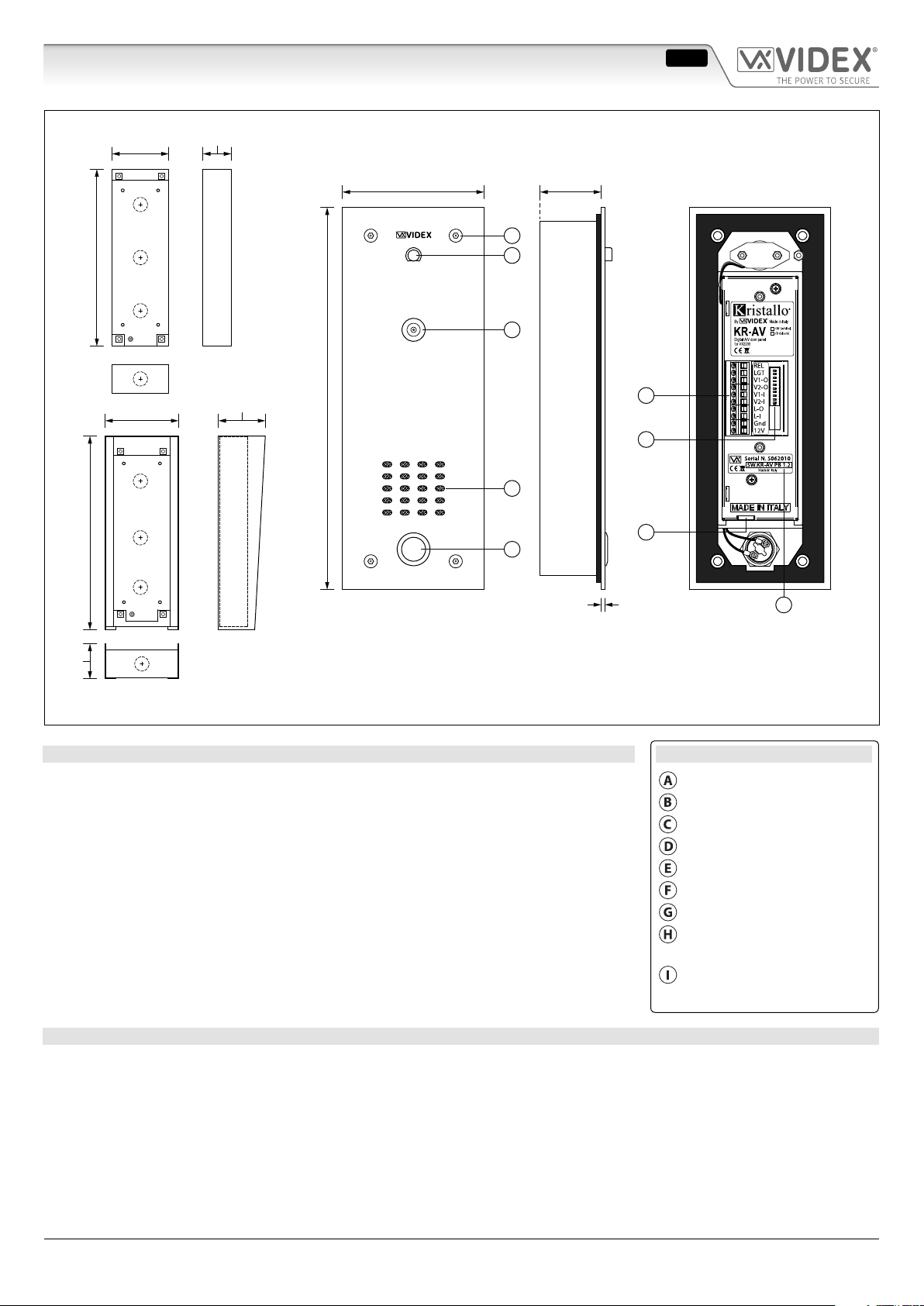
Art.KR-AV-VR Vandal Resistant Digital A/V Door Panel for VX2200
250mm
274mm
80mm
104mm
40mm
VRFB100x270
Flush Box
65mm
270mm
100mm 40mm
A
B
C
D
E
Rear View
DSW1
F
G
H
ON
Front View
KR-AV-VR-SB
50mm
Fig. 1
Surface Box
DESCRIPTION
Vandal Resistant Digital audio/video door entry panel for internal or external use, to work
with the VIDEX VX2200 digital system and is available with a ush back box (VRFB100x270)
as standard or optional surface back box (KR-AV-VR-SB), see Fig.1.
Normally used on installations where each property or apartment requires a local intercom
door station directly outside their property or apartment.
The panel includes an HD colour camera (650 lines with 90º of viewing angle) plus the speaker
unit module and a single call button.
10 Way dip-switch bank (DSW1) of which 8 (1 to 8) are used to set the address of the
videophone to call, the ninth is used to set the door opening time (2 seconds = OFF, 6
seconds = ON). The tenth is not used.
Loudspeaker and microphone volume adjustable through two trimmers on the bottom of
2.5mm
I
LEGEND
Countersunk Security Screws
Microphone
Colour Camera
Speaker
Call Button
Connection Terminals
Dip-switch (DSW1)
Microphone & loudspeaker
trimmer
Current Firmware
(SW.KR-AV PB 1.2)
the unit. Block exchangers are not required.
OPERATION
To Call the Apartment
Press the call button on the panel:
• The KR-AV-VR panel will call the apartment emitting a low volume beep at 2 second intervals (approx.).
• When the apartment answers the conversation can begin.
• When the conversation is nished and the call is closed down the panel will revert back to standby mode.
In the event that the videophone is in privacy mode or if there is no answer (system busy), the call will stop automatically after
approximately 40 seconds.
Art.KR-AV-VR - Installation Instructions
- 1 -
ENUK - V1.0 - 08/06/18
Page 2
Kristallo Series
Art. KR-AV-VR Vandal Resistant Digital A/V Door Panel for VX2200
If the call is answered and the conversation is not closed down by the user the call will terminate automatically after approximately
60 seconds.
To Open the Door from the Videophone (when the conversation is open)
Press the lock button on the Videophone:
• The “REL” output terminal on the panel (see Fig.1 reference “F”) will be triggered and activate the relay connected to the lock
(see Fig.3 and Fig.4 on page 5 for relay and lock wiring).
• The panel will emit 4 quick, successive low volume beeps to indicate the lock has been triggered.
PROGRAMMING & ADJUSTMENTS
Programming options are:
• The Phone ID (address) of the local videophone to call when the call button is pressed (see Fig.1 reference “G”, 10 way dip-
switch bank DSW1, switches 1 to 8).
• The door opening time (the “REL” output) for the electric lock (switch 9).
• Switch 10 is not used.
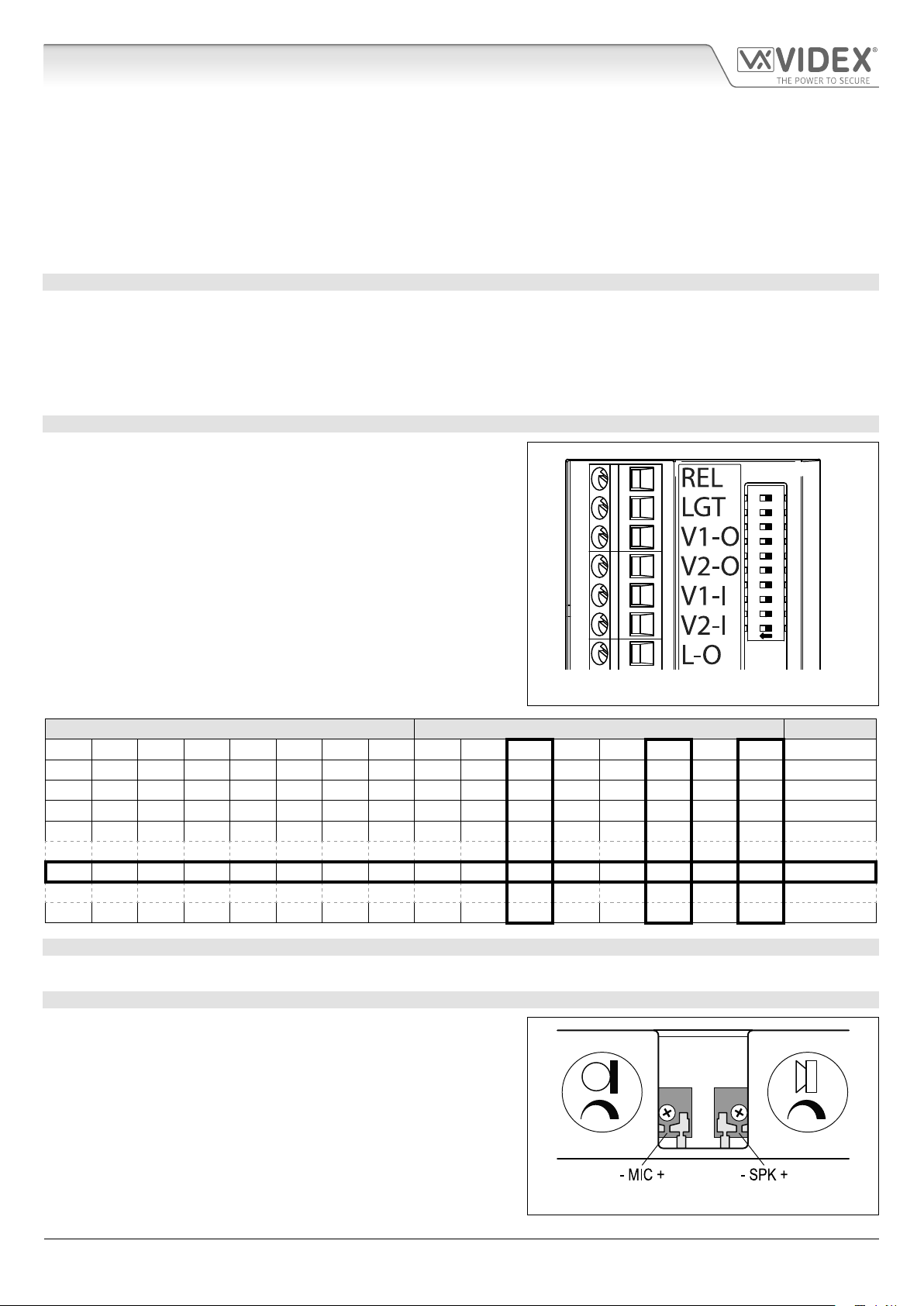
LOCAL VIDEOPHONE PHONE ID SETUP
Use the rst 8 dip-switches of the 10 way dip-switch bank (see Fig.2) to
set the PHONE ID for the local videophone.
Each switch corresponds to one bit which can have a value of 0 (OFF) or
1 (ON).
Each bit corresponds to a decimal weight depending on the position:
Switch 1 = decimal 1, 2=2, 3=4, 4=8, 5=16, 6=32, 7=64 and 8=128
(see table below). I.E to set the address 37, put switches 1, 3 and 6 ON
(1+4+32=37).
ON
DSW1
2 3 4 5 6 7 8 9 10
1
Fig. 2
SWITCHES DECIMAL WEIGHT ADDRESS
8 7 6 5 4 3 2 1 128 64 32 16 8 4 2 1
OFF OFF OFF OFF OFF OFF OFF ON 0 0 0 0 0 0 0 1 1
OFF OFF OFF OFF OFF OFF ON OFF 0 0 0 0 0 0 1 0 2
OFF OFF OFF OFF OFF OFF ON ON 0 0 0 0 0 0 1 1 3
OFF OFF OFF OFF OFF ON OFF OFF 0 0 0 0 0 1 0 0 4
OFF OFF ON OFF OFF ON OFF ON 0 0 1 0 0 1 0 1 37
ON OFF ON ON OFF ON OFF OFF 1 0 1 1 0 1 0 0 180
DOOR OPENING TIME SETUP
Switch 9 (refer to Fig.2) sets the door opening time (the “REL” output): OFF = 2 seconds, ON = 6 seconds.
VOLUME ADJUSTMENT
Volume adjustment trimmers are available for both the microphone and
speaker which are located at the bottom of the KR-AV unit (see Fig.1
reference “H”).
Mic and Speaker volume adjustments
Turning the mic or speaker adjustment trimmer clockwise will increase
the volume and turning the mic or speaker adjustment timmer counterclockwise will decrease the volume, see Fig.3.
Art.KR-AV-VR - Installation Instructions
- 2 -
Fig. 3
ENUK - V1.0 - 08/06/18
Page 3

Kristallo Series
Art. KR-AV-VR Vandal Resistant Digital A/V Door Panel for VX2200
TERMINALS
REL Open collector active low output Vdc 100mA max enabled by lock release button on videophone
LGT Terminal not used
V1-O Video signal V1 output towards the local videophone
V2-O Video signal V2 output towards the local videophone
V1-I Video signal V1 input from the main intercom door station
V2-I Video signal V2 input from the main intercom door station
L-O Data BUS out towards the local videophone
L-I Data BUS in from the main intercom door station
Gnd 12Vdc power supply ground and Data BUS -(negative) connection
12V 12Vdc power supply input
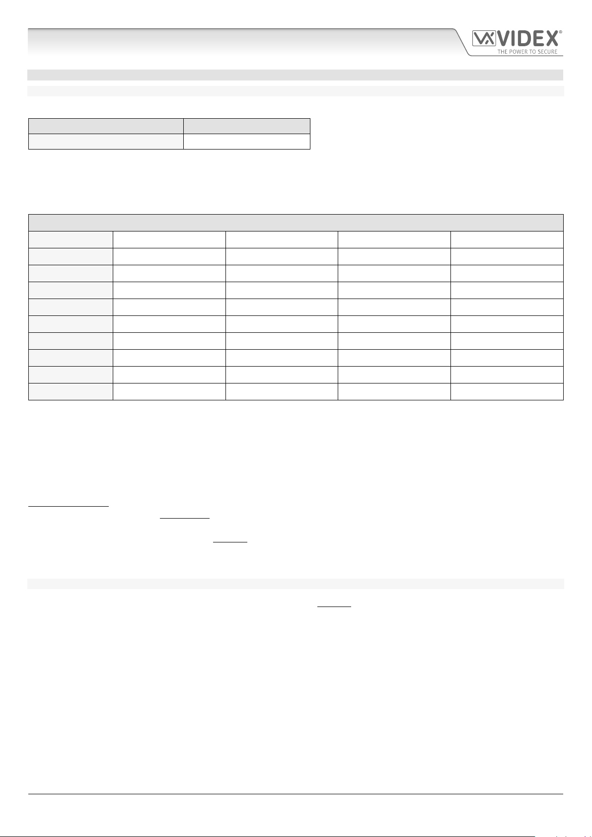
TECHNICAL SPECIFICATION
Power supply voltage: 12÷14Vdc
Power consumption: Stand-by: 6mA max (on 12Vdc)
Operating: 200mA Max (on 12Vdc)
Working temperature: -10° +50° C
Art.KR-AV-VR - Installation Instructions
- 3 -
ENUK - V1.0 - 08/06/18
Page 4
Kristallo Series
Art. KR-AV-VR Vandal Resistant Digital A/V Door Panel for VX2200
GENERAL DIRECTIONS FOR INSTALLATION
CABLE SIZE GUIDE
Refer to the table below for the power supply output connections to the KR-AV-VR panel and the lock release connections.
Distance 20m
Cross Sectional Area (CSA) 0.5mm
Ideally the power supply should be located as close to the KR-AV-VR panel as possible for best performance. The maximum
acceptable resistance for the above cables = 3Ω or less for best possible performance.
For other VX2200 system devices refer to the following table. It is recommended that a twisted pair cable is used for the L and databus connections and for balanced video signal connections V1-I / V1-O and V2-I / V2-O.
VX2200 System Cable Requirements
Connections 50m 100m 200m 300m
L 0.4mm
- 0.4mm
V1 (V1-I / V1-O)* 0.35mm
V2 (V2-I / V2-O)* 0.35mm
+20V * 0.5mm
GNDV * 0.5mm
+12V 0.4mm
GND 0.4mm
All others ** 0.25mm
2
2
2
2
2
2
2
2
2
2
0.5mm
0.5mm
0.5mm
0.5mm
0.75mm
0.75mm
0.75mm
0.75mm
0.35mm
2
2
2
2
2
2
2
2
2
0.75mm
0.75mm
0.75mm
0.75mm
1.0mm
1.0mm
1.0mm
1.0mm
0.5mm
2
2
2
2
2
2
2
2
2
0.75mm
1.0mm
1.0mm
1.0mm
1.0mm
1.5mm
1.5mm
1.5mm
1.5mm
2
2
2
2
2
2
2
2
2
* - these connections are only required on video systems.
** - these are optional connections (e.g. door monitoring LED).
The maximum acceptable resistance for all the above connections (except +20V and GNDV) = 7.5 Ohms and the maximum
acceptable resistance for the video connections +20V and GNDV = 5 Ohms for best possible performance. Please note that all cable
sizes shown in the tables above are the minimum cable requirements. Also note that additional consideration should be given
when selecting and using internal and external grade cable and should be used where appropriate.
IMPORTANT NOTE: Only bare copper (BC) cable should be used (solid or stranded is acceptable). Please be aware that when
selecting a cable the following should NOT be used: Copper Coated Steel (CCS) and Copper Clad Aluminium (CCA). While these
types of cable may oer a low cost solution they will have a higher resistance than pure copper cable and can aect the overall
performance of the system therefore Videx DO NOT recommend these types of cable.
Further cabling information can be found in the technical manual VX2200Blocks1-2 and is also provided in any accompanying
installation instructions with the various audio/videophones and hands-free devices.
GENERAL INSTALLATION NOTES
• Check that all components are free from damage before installing (DO NOT proceed with installation in the event of damage).
• Keep all packaging away from children.
• Do not obstruct the ventilation openings or slots on any of the devices.
• All connections to mains voltages must be made to the current national standards (I.E.E. wiring regulations for the UK or the
appropriate standards of your country).
• Install an appropriate fused spur or isolation switch to isolate the mains where necessary and always isolate the mains before
carrying out any maintenance work on the system.
• Avoid water ingress into the rear of the panel (or other devices) always seal the panel’s back box frame during installation using
a suitable silicon based sealant (also refer to back box installation notes on pages 6 and 7).
• All intercom and access control cables must be routed separately from the mains and other high voltage cables (ideally in
separate cable ducts/trays or where this is not possible should be kept apart at a distance of no less than 30cm (12” approx.) if
running in the same cable duct/tray.
Art.KR-AV-VR - Installation Instructions
- 4 -
ENUK - V1.0 - 08/06/18
Page 5

Kristallo Series
Art. KR-AV-VR Vandal Resistant Digital A/V Door Panel for VX2200
ELECTRIC LOCK AND VOLT FREE CONNECTIONS
An electric lock (fail safe or fail secure) cannot be connected directly to the KR-AV unit. The “REL” output can be connected to a
remote relay (Art.506N) which can then be connected directly to the lock. An additional 12Vac or dc power supply (depending on
the type of lock tted) may also be required. Follow Fig.4 for fail secure lock release wiring and Fig.5 for fail safe lock release wiring.
If volt free wiring is required, e.g. volt free connections to a set of gate or barrier controls, then simply follow Fig.4 but omit the lock
wiring and instead connect the CO/NO relay terminals directly into the appropriate trigger input on the gate or barrier controls.
KR-AV-VR
Terminals
Art.506N
VOLT
FREE
12Vac/dc
FAIL SECURE
GND+12V
dc
ac/dc
LOCK RELEASE
GND+12V
KR-AV-VR
Terminals
Art.506N
12Vdc
FAIL SAFE
GND+12V
dc
ac/dc
LOCK RELEASE
GND+12V
Fig. 4 Fig. 5
EARTHING THE FRONT PANEL TO THE BACK BOX
It is important to earth the KR-AV-VR panel’s front plate to the
back box with the appropriate xings and earth strap provided.
Refer to Fig.6 and follow the steps below:
• First place the M4 at washer followed by the M4 spring
M4 nut
earth stud
top
view
washer over the earth stud on the front plate;
• Next place the eyelet of one end of the earth strap on top
of the M4 spring washer;
• Finally t the M4 nut on top of the earth strap eyelet and
tighten rmly into place;
• Repeat the steps above when tting the other end of the
earth strap to the earth stud inside the back box.
M4 spring
washer
M4 washer
Fig. 6
earth strap
VR plate
• The earth stud connection inside the back box should then be connected in the same way to the building’s earth connection.
PANEL CARE AND MAINTENANCE
As the panel is manufactured from 12 gauge brushed stainless steel it is important that the VR plate is cleaned on a regular basis
to prevent dirt build up and tarnishing. A clean and soft cloth can be used with moderate warm water or non-aggressive cleansers.
Additional care should be taken to follow the grain of the metal when polishing and always only polish in one direction to avoid
light scratching of the plate. Also try to avoid any polish build up around the panel’s button which may prevent the button from
operating correctly.
DO NOT USE ANY OF THE FOLLOWING:
• Abrasive liquids;
• Chlorine-based liquids;
• Metal cleaning products (including Sidol stainless steel cleaner as this can aect the engraving);
• Hydrochloride bleaches.
Art.KR-AV-VR - Installation Instructions
- 5 -
ENUK - V1.0 - 08/06/18
Page 6

Kristallo Series
130 - 160cm
w
h
d
ON
ON
Torx pin key
Art. KR-AV-VR Vandal Resistant Digital A/V Door Panel for VX2200
FLUSH BACK BOX INSTALLATION VRFB100X270
Fig. 7 Fig. 8 Fig. 9
Fig. 10 Fig. 11
1. The ush back box should be ushed into the wall. It is recommended that the KR-AV-VR panel is tted at a height of approx.
130-160cm from the oor level to the centre of the camera lens, see Fig.7;
2. Using the ush box and the hole dimensions: VRFB100x270 (w=80mm x h=270mm x d=40mm), Fig.8, use appropriate tools to cut
out the recommended hole size in the wall (where necessary wear the appropriate protective clothing when doing this). Remember
to allow room for the connecting cables;
In order to prevent water ingress we highly recommend using a silicon sealant between the wall and the ush box, ON
THE LEFT, TOP AND RIGHT SIDES ONLY AND ENSURE ALL THE CABLE ENTRY HOLES ARE SEALED. DON'T USE SILICON
SEALANT ON THE BOTTOM SIDE OF THE BACK BOX Fig.9;
3. Embed the ush box into the wall. Feed the connecting cables through the knockouts required in the ush box (see Fig.10) and
make all necessary connections between the cable and the KR-AV-VR panel following the wiring diagram on page 9. Connect the
earth strap as described on page 5 (also refer to Fig.6);
4. Make any other necessary panel adjustments required (dip-switch settings, speech volume adjustments etc.). After the system has
been tested and is working correctly place the KR-AV-VR panel back into the ush box and x it using the screwdriver (using the
torx end) or torx pin key provided and the torx pin security screws (see Fig.11). Note: do not over tighten the screws more than
is necessary.
Art.KR-AV-VR - Installation Instructions
- 6 -
ENUK - V1.0 - 08/06/18
Page 7

Kristallo Series
130 - 160cm
A
A
C
D
B
E
A
ON
ON
Torx pin key
Art. KR-AV-VR Vandal Resistant Digital A/V Door Panel for VX2200
SURFACE BACK BOX INSTALLATION KRAVVRSB
Fig. 12 Fig. 13 Fig. 14
Fig. 15 Fig. 16
1. The surface box should be mounted to the wall at a height of approximately 130-160cm from the oor level to the centre of
the camera lens of the KR-AV-VR panel, Fig.12. Place the surface box
wall plugs
In order to prevent water ingress we highly recommend using a silicon sealant between the wall and the surface box
, ON THE LEFT, TOP AND RIGHT SIDES ONLY AND ENSURE ALL THE CABLE ENTRY HOLES ARE SEALED. DON'T USE
SILICON SEALANT ON THE BOTTOM SIDE OF THE BACK BOX Fig.13;
2. Drill the 4 xing holes , insert the wall plugs and feed the cables through the surface box knockout required. Fix the surface
box to the wall using self-tapping masonry screws
3. Feed the connecting cables through the knockouts required in the surface box (see Fig.15) and make all necessary connections
between the cable and the KR-AV-VR panel following the wiring diagram on page 9. Connect the earth strap as described on page
5 (also refer to Fig.6);
4. Make any other necessary panel adjustments required (dip-switch settings, speech volume adjustments etc.). After the system has
been tested and is working correctly place the KR-AV-VR panel back into the surface box and x it using the screwdriver (using the
torx end) or torx pin key provided and the torx pin security screws (see Fig.16). Note: do not over tighten the screws more than
is necessary.
and the hole for the cables , see Fig.14;
, see Fig.14, remember to allow room for the connecting cables;
against the wall and mark the 4 xing holes for the
Art.KR-AV-VR - Installation Instructions
- 7 -
ENUK - V1.0 - 08/06/18
Page 8

Kristallo Series
knockout xings
knockout cover
at-head screwdriver
‘tap out’ knockout xing
knockout
xing
removed
push down on the knockout
ease the knockout
back and forth to
remove
t a Ø20mm
rubber
grommet
to the
knockout hole
SOLID WALL
Base of back box
40mm, Ø4mm wall
plug embeded into
the wall
40mm, Ø3.5mm
self-tapping masonry
screw
Art. KR-AV-VR Vandal Resistant Digital A/V Door Panel for VX2200
ADDITIONAL BACK BOX INSTALLATION NOTES
REMOVING THE BACK BOX KNOCKOUTS
Due care should be taken when removing the knockout(s) on the base of the back box to avoid personal injury. Where necessary use
the appropriate tools and wear the appropriate protective clothing (gloves, eye protection etc.) when removing the knockouts.
1. Before embeding the ush box into the wall or mounting the surface box to the wall it is advised to rst remove the knockout(s)
required;
2. Take a at-head screwdriver and use the at end to gently ‘tap out’ and apply pressure to the knockout xing, see Fig.17 and Fig.18;
3. Once the knockout xing has been removed, Fig.19, push down on the knockout, see Fig.20;
4. Using a set of pliers grip the end of the knockout and ease it back and forth, Fig.21, until the other knockout xing fatigues and the
knockout breaks away from the base of the back box. If necessary le down and smooth out any rough edges with a metal le;
5. Fit a Ø20mm rubber grommet into the knockout hole, see Fig.22.
Fig. 17 Fig. 18 Fig. 19
Fig. 20 Fig. 21 Fig. 22
EMBEDING AND FIXING THE BACK BOX TO THE WALL
The ush box and surface back box need to be embeded or xed to the wall respectively,
therefore a suitable set of masonry screws and wall plugs should be used to do this. It
is recommended that 4x 40mm, Ø3.5mm self-tapping masonry screws with 4x 40mm,
Ø4mm nylon type wall plugs are used, see Fig.23.
Where necessary use the appropriate power tools and wear the appropriate protective
clothing (gloves, eye protection etc.) when drilling the xing holes to mount the box
and cutting out the hole in the wall to embed the ush box.
USING SILICON
Whenever using silicon sealant remember to wash your hands after use and always
discard of any excess silicon waste responsibly.
Art.KR-AV-VR - Installation Instructions
- 8 -
Fig. 23
ENUK - V1.0 - 08/06/18
Page 9

Kristallo Series
EMAIL: tech@videxuk.com
Art. KR-AV-VR Vandal Resistant Digital A/V Door Panel for VX2200
WIRING DIAGRAM
V1V2
L
Gnd-L
KR-AV-VR
Panel Address ID. 2
REL
LGT
V1-O
V2-O
V1-I
V2-I
L-O
L-I
Gnd
12V
Art.506N
5
4
3
2
1
NO2
NC2
CO2
NO1
NC1
C01
SE
12Vac
13V
ART.521B
115
0
Art.4202RV
B.V.
coax
ON/OFF
KR-AV-VR
Panel Address ID. 1
DSW1 DSW1
REL
LGT
V1-O
V2-O
V1-I
V2-I
L-O
L-I
Gnd
12V
Art.506N
5
NO2
4
NC2
3
CO2
2
NO1
NC1
1
C01
+B
+
swsw
Art.6272
Address N.2
SE
12Vac
Art.KRV78
Address N.1
Art.6272
Art.KRV78
SE
12Vac
STANDARD MODE
(MASTER)
Art.KR-AV-VR - Installation Instructions
316x
others
- 9 -
Dip-Switch Settings:
= OFF = ON
Please note that shaded area
represents dip-switch position.
VIDEX SECURITY LTD
TECHNICAL HELP: TEL: 0191 224 3174
FAX: 0191 224 4938
DATE: 10/05/18 INITIAL: PH REF: sp2200wd25d-V2
DESCRIPTION: VX2200 video system with main digital
entrance and local KR-AV-VR sub-entrances
ENUK - V1.0 - 08/06/18
Page 10

Kristallo Series
Art. KR-AV-VR Addresses 1..127 Table for dip-switch banks with ON position up
10
11
12
13
14
15
1 2 3 4 5 6 7 8
31
1 2 3 4 5 6 7 8
47
1 2 3 4 5 6 7 8
5
6
7
8
9
ON
ON
ON
ON
ON
ON
ON
ON
ON
ON
ON
ON
ON
1 2 3 4 5 6 7 8
30
1 2 3 4 5 6 7 8
46
1 2 3 4 5 6 7 8
1 2 3 4 5 6 7 8
29
ON
ON
1 2 3 4 5 6 7 8
45
ON
ON
1 2 3 4 5 6 7 8
1 2 3 4 5 6 7 8
28
1 2 3 4 5 6 7 8
44
1 2 3 4 5 6 7 8
1 2 3 4 5 6 7 8
27
ON
ON
1 2 3 4 5 6 7 8
43
ON
ON
1 2 3 4 5 6 7 8
1 2 3 4 5 6 7 8
26
1 2 3 4 5 6 7 8
42
1 2 3 4 5 6 7 8
1 2 3 4 5 6 7 8
25
ON
ON
1 2 3 4 5 6 7 8
41
ON
ON
1 2 3 4 5 6 7 8
1 2 3 4 5 6 7 8
24
1 2 3 4 5 6 7 8
40
1 2 3 4 5 6 7 8
1 2 3 4 5 6 7 8
23
ON
ON
1 2 3 4 5 6 7 8
39
ON
ON
1 2 3 4 5 6 7 8
1 2 3 4 5 6 7 8
22
1 2 3 4 5 6 7 8
38
1 2 3 4 5 6 7 8
1 2 3 4 5 6 7 8
21
ON
ON
1 2 3 4 5 6 7 8
37
ON
ON
1 2 3 4 5 6 7 8
4
1 2 3 4 5 6 7 8
20
1 2 3 4 5 6 7 8
36
1 2 3 4 5 6 7 8
3
ON
ON
1 2 3 4 5 6 7 8
19
ON
ON
1 2 3 4 5 6 7 8
35
ON
ON
1 2 3 4 5 6 7 8
2
1 2 3 4 5 6 7 8
18
1 2 3 4 5 6 7 8
34
1 2 3 4 5 6 7 8
1/2
1
ON
ON
1 2 3 4 5 6 7 8
16
17
ON
ON
ON
ON
1 2 3 4 5 6 7 8
33
1 2 3 4 5 6 7 8
1 2 3 4 5 6 7 8
32
ON
ON
1 2 3 4 5 6 7 8
= ON
= OFF
63
1 2 3 4 5 6 7 8
79
1 2 3 4 5 6 7 8
95
1 2 3 4 5 6 7 8
111
1 2 3 4 5 6 7 8
48
49
50
51
52
53
54
55
56
57
58
59
60
61
62
ON
ON
ON
ON
ON
ON
ON
ON
ON
ON
ON
ON
ON
ON
ON
ON
1 2 3 4 5 6 7 8
78
ON
ON
1 2 3 4 5 6 7 8
94
ON
ON
1 2 3 4 5 6 7 8
110
ON
ON
1 2 3 4 5 6 7 8
1 2 3 4 5 6 7 8
77
ON
1 2 3 4 5 6 7 8
93
ON
1 2 3 4 5 6 7 8
109
ON
1 2 3 4 5 6 7 8
1 2 3 4 5 6 7 8
76
ON
1 2 3 4 5 6 7 8
92
ON
1 2 3 4 5 6 7 8
108
ON
1 2 3 4 5 6 7 8
1 2 3 4 5 6 7 8
75
ON
1 2 3 4 5 6 7 8
91
ON
1 2 3 4 5 6 7 8
107
ON
1 2 3 4 5 6 7 8
1 2 3 4 5 6 7 8
74
ON
1 2 3 4 5 6 7 8
90
ON
1 2 3 4 5 6 7 8
106
ON
1 2 3 4 5 6 7 8
1 2 3 4 5 6 7 8
73
ON
1
2 3 4 5 6 7 8
89
ON
1 2 3 4 5 6 7 8
105
ON
1 2 3 4 5 6 7 8
1 2 3 4 5 6 7 8
72
ON
1 2 3 4 5 6 7 8
88
ON
1 2 3 4 5 6 7 8
104
ON
1 2 3 4 5 6 7 8
1 2 3 4 5 6 7 8
71
ON
1 2 3 4 5 6 7 8
87
ON
1 2 3 4 5 6 7 8
103
ON
1 2 3 4 5 6 7 8
1 2 3 4 5 6 7 8
70
ON
1 2 3 4 5 6 7 8
86
ON
1 2 3 4 5 6 7 8
102
ON
1 2 3 4 5 6 7 8
1 2 3 4 5 6 7 8
69
ON
1 2 3 4 5 6 7 8
85
ON
1 2 3 4 5 6 7 8
101
ON
1 2 3 4 5 6 7 8
1 2 3 4 5 6 7 8
68
ON
1 2 3 4 5 6 7 8
84
ON
1 2 3 4 5 6 7 8
100
ON
1 2 3 4 5 6 7 8
1 2 3 4 5 6 7 8
67
1 2 3 4 5 6 7 8
83
1 2 3 4 5 6 7 8
99
1 2 3 4 5 6 7 8
1 2 3 4 5 6 7 8
66
ON
ON
1 2 3 4 5 6 7 8
82
ON
ON
1 2 3 4 5 6 7 8
98
ON
ON
1 2 3 4 5 6 7 8
1 2 3 4 5 6 7 8
65
1 2 3 4 5 6 7 8
81
1 2 3 4 5 6 7 8
97
1 2 3 4 5 6 7 8
1 2 3 4 5 6 7 8
64
ON
ON
1 2 3 4 5 6 7 8
80
ON
ON
1 2 3 4 5 6 7 8
96
ON
ON
1 2 3 4 5 6 7 8
124
125
126
127
ON
ON
ON
ON
1 2 3 4 5 6 7 8
1 2 3 4 5 6 7 8
1 2 3 4 5 6 7 8
1 2 3 4 5 6 7 8
Art.KR-AV-VR - Installation Instructions
123
ON
1 2 3 4 5 6 7 8
122
ON
1 2 3 4 5 6 7 8
121
ON
1 2 3 4 5 6 7 8
120
ON
1 2 3 4 5 6 7 8
112
113
114
115
116
117
118
119
ON
ON
ON
ON
ON
ON
ON
ON
1 2 3 4 5 6 7 8
1 2 3 4 5 6 7 8
1 2 3 4 5 6 7 8
1 2 3 4 5 6 7 8
1 2 3 4 5 6 7 8
1 2 3 4 5 6 7 8
- 10 -
1 2 3 4 5 6 7 8
1 2 3 4 5 6 7 8
ENUK - V1.0 - 08/06/18
Page 11

Kristallo Series
Art. KR-AV-VR Addresses 128..255 Table for dip-switch banks with ON position up
130
131
132
133
134
135
136
137
138
139
140
141
142
143
ON
ON
ON
ON
ON
ON
ON
ON
ON
ON
ON
ON
ON
ON
1 2 3 4 5 6 7 8
159
ON
1 2 3 4 5 6 7 8
175
ON
1 2 3 4 5 6 7 8
1 2 3 4 5 6 7 8
158
ON
1 2 3 4 5 6 7 8
174
ON
1 2 3 4 5 6 7 8
1 2 3 4 5 6 7 8
157
ON
1 2 3 4 5 6 7 8
173
ON
1 2 3 4 5 6 7 8
1 2 3 4 5 6 7 8
156
ON
1 2 3 4 5 6 7 8
172
ON
1 2 3 4 5 6 7 8
1 2 3 4 5 6 7 8
155
ON
1 2 3 4 5 6 7 8
171
ON
1 2 3 4 5 6 7 8
1 2 3 4 5 6 7 8
154
ON
1 2 3 4 5 6 7 8
170
ON
1 2 3 4 5 6 7 8
1 2 3 4 5 6 7 8
153
ON
1 2 3 4 5 6 7 8
169
ON
1 2 3 4 5 6 7 8
1 2 3 4 5 6 7 8
152
ON
1 2 3 4 5 6 7 8
168
ON
1 2 3 4 5 6 7 8
1 2 3 4 5 6 7 8
151
ON
1 2 3 4 5 6 7 8
167
ON
1 2 3 4 5 6 7 8
1 2 3 4 5 6 7 8
150
ON
1 2 3 4 5 6 7 8
166
ON
1 2 3 4 5 6 7 8
1 2 3 4 5 6 7 8
149
ON
1 2 3 4 5 6 7 8
165
ON
1 2 3 4 5 6 7 8
1 2 3 4 5 6 7 8
148
ON
1 2 3 4 5 6 7 8
164
ON
1 2 3 4 5 6 7 8
1 2 3 4 5 6 7 8
147
ON
1 2 3 4 5 6 7 8
163
ON
1 2 3 4 5 6 7 8
1 2 3 4 5 6 7 8
146
ON
1 2 3 4 5 6 7 8
162
ON
1 2 3 4 5 6 7 8
129
ON
1 2 3 4 5 6 7 8
145
ON
1 2 3 4 5 6 7 8
161
ON
1 2 3 4 5 6 7 8
128
ON
1 2 3 4 5 6 7 8
144
ON
1 2 3 4 5 6 7 8
160
ON
1 2 3 4 5 6 7 8
= ON
2/2
= OFF
191
ON
1 2 3 4 5 6 7 8
207
ON
1 2 3 4 5 6 7 8
223
ON
1 2 3 4 5 6 7 8
239
ON
1 2 3 4 5 6 7 8
190
ON
1 2 3 4 5 6 7 8
206
ON
1 2 3 4 5 6 7 8
222
ON
1 2 3 4 5 6 7 8
238
ON
1 2 3 4 5 6 7 8
189
ON
1 2 3 4 5 6 7 8
205
ON
1 2 3 4 5 6 7 8
221
ON
1 2 3 4 5 6 7 8
237
ON
1 2 3 4 5 6 7 8
188
ON
1 2 3 4 5 6 7 8
204
ON
1 2 3 4 5 6 7 8
220
ON
1 2 3 4 5 6 7 8
236
ON
1 2 3 4 5 6 7 8
187
ON
1 2 3 4 5 6 7 8
203
ON
1 2 3 4 5 6 7 8
219
ON
1 2 3 4 5 6 7 8
235
ON
1 2 3 4 5 6 7 8
186
ON
1 2 3 4 5 6 7 8
202
ON
1 2 3 4 5 6 7 8
218
ON
1 2 3 4 5 6 7 8
234
ON
1 2 3 4 5 6 7 8
185
ON
1 2 3 4 5 6 7 8
201
ON
1 2 3 4 5 6 7 8
217
ON
1 2 3 4 5 6 7 8
233
ON
1 2 3 4 5 6 7 8
184
ON
1 2 3 4 5 6 7 8
200
ON
1 2 3 4 5 6 7 8
216
ON
1 2 3 4 5 6 7 8
232
ON
1 2 3 4 5 6 7 8
183
ON
1 2 3 4 5 6 7 8
199
ON
1 2 3 4 5 6 7 8
215
ON
1 2 3 4 5 6 7 8
231
ON
1 2 3 4 5 6 7 8
182
ON
1 2 3 4 5 6 7 8
198
ON
1 2 3 4 5 6 7 8
214
ON
1 2 3 4 5 6 7 8
230
ON
1 2 3 4 5 6 7 8
181
ON
1 2 3 4 5 6 7 8
197
ON
1 2 3 4 5 6 7 8
213
ON
1 2 3 4 5 6 7 8
229
ON
1 2 3 4 5 6 7 8
180
ON
1 2 3 4 5 6 7 8
196
ON
1 2 3 4 5 6 7 8
212
ON
1 2 3 4 5 6 7 8
228
ON
1 2 3 4 5 6 7 8
179
ON
1 2 3 4 5 6 7 8
195
ON
1 2 3 4 5 6 7 8
211
ON
1 2 3 4 5 6 7 8
227
ON
1 2 3 4 5 6 7 8
178
ON
1 2 3 4 5 6 7 8
194
ON
1 2 3 4 5 6 7 8
210
ON
1 2 3 4 5 6 7 8
226
ON
1 2 3 4 5 6 7 8
177
ON
1 2 3 4 5 6 7 8
193
ON
1 2 3 4 5 6 7 8
209
ON
1 2 3 4 5 6 7 8
225
ON
1 2 3 4 5 6 7 8
176
ON
1 2 3 4 5 6 7 8
192
ON
1 2 3 4 5 6 7 8
208
ON
1 2 3 4 5 6 7 8
224
ON
1 2 3 4 5 6 7 8
252
253
254
255
ON
ON
ON
ON
1 2 3 4 5 6 7 8
1 2 3 4 5 6 7 8
1 2 3 4 5 6 7 8
1 2 3 4 5 6 7 8
Art.KR-AV-VR - Installation Instructions
251
ON
1 2 3 4 5 6 7 8
250
ON
1 2 3 4 5 6 7 8
249
ON
1 2 3 4 5 6 7 8
248
ON
1 2 3 4 5 6 7 8
247
ON
1 2 3 4 5 6 7 8
246
1 2 3 4 5 6 7 8
- 11 -
240
241
242
243
244
245
ON
ON
ON
ON
ON
ON
ON
1 2 3 4 5 6 7 8
1 2 3 4 5 6 7 8
1 2 3 4 5 6 7 8
1 2 3 4 5 6 7 8
1 2 3 4 5 6 7 8
1 2 3 4 5 6 7 8
ENUK - V1.0 - 08/06/18
Page 12

El producto lleva la marca CE que demuestra su conformidad y puede ser
Het product heeft de CE-markering om de conformiteit ervan aan te tonen en
gen. Dit product volgt de bepalingen van de Europese Richtlijnen 2014/30/EU
Le produit est marqué CE à preuve de sa conformité et peut être distribué
The product is CE marked demonstrating its conformity and is for distribution
Il prodotto è marchiato CE a dimostrazione della sua conformità e può essere
MANUFACTURER
FABBRICANTE
FABRICANT
FABRICANTE
FABRIKANT
VIDEX ELECTRONICS S.P.A.
Via del Lavoro, 1
63846 Monte Giberto (FM) Italy
Tel (+39) 0734 631669
Fax (+39) 0734 632475
www.videx.it - info@videx.it
CUSTOMER SUPPORT
SUPPORTO CLIENTI
SUPPORTS CLIENTS
ATENCIÓN AL CLIENTE
KLANTENDIENST
VIDEX ELECTRONICS S.P.A.
www.videx.it - technical@videx.it
Tel: +39 0734-631669
Fax: +39 0734-632475
Main UK oce:
VIDEX SECURITY LTD
1 Osprey Trinity Park
Trinity Way
LONDON E4 8TD
Phone: (+44) 0870 300 1240
Fax: (+44) 020 8523 5825
www.videxuk.com
marketing@videxuk.com
Greece oce:
VIDEX HELLAS Electronics
48 Filolaou Str.
11633 ATHENS
Phone: (+30) 210 7521028
(+30) 210 7521998
Fax: (+30) 210 7560712
www.videx.gr
videx@videx.gr
UK Customers only:
VIDEX SECURITY LTD
www.videxuk.com
Tech Line: 0191 224 3174
Fax: 0191 224 1559
Northern UK oce:
VIDEX SECURITY LTD
Unit 4-7
Chillingham Industrial Estate
Chapman Street
NEWCASTLE UPON TYNE - NE6 2XX
Tech Line: (+44) 0191 224 3174
Phone: (+44) 0870 300 1240
Fax: (+44) 0191 224 1559
Danish oce:
VIDEX DANMARK
Hammershusgade 15
DK-2100 COPENHAGEN
Phone: (+45) 39 29 80 00
Fax: (+45) 39 27 77 75
www.videx.dk
videx@videx.dk
Benelux oce:
NESTOR COMPANY NV
E3 laan, 93
B-9800 Deinze
Phone: (+32) 9 380 40 20
Fax: (+32) 9 380 40 25
www.videx.be
info@videx.be
within all member states of the EU with no restrictions. This product follows
the provisions of the European Directives 2014/30/EU (EMC); 2014/35/EU
(LVD); 2011/65/EU (RoHS): CE marking 93/68/EEC.
librement à l’intérieur des pays membres de l’union européenne EU.
Ce produit est conforme aux directives européennes 2014/30/EU (EMC) ;
2014/35/EU (LVD) ; 2011/65/EU (RoHS): marquage CE 93/68/EEC.
is bestemd voor distributie binnen de lidstaten van de EU zonder beperkin-
(EMC); 2014/35/EU (LVD); 2011/65/EU (RoHS): CE-markering 93/68/EEG.
Dutch oce:
NESTOR COMPANY BV
Business Center Twente (BCT )
Grotestraat, 64
NL-7622 GM Borne
www.videxintercom.nl
info@videxintercom.nl
distribuito liberamente all’interno dei paesi membri dell’Unione Europea UE.
Questo prodotto è conforme alle direttive Europee: 2014/30/UE (EMC);
2014/35/UE (LVD); 2011/65/UE (RoHS): marcatura CE 93/68/EEC.
distribuido en todos los estados miembros de la unión europea UE.
Este producto cumple con las Directivas Europeas 2014/30/EU (EMC);
2014/35/EU (LVD); 2011/65/EU (RoHS): marca CE 93/68/EEC.
 Loading...