

Page 1

66250935-EN - V1.2 - 15/01/16
1
Kristallo Series
Art.KR-AV - Installation instructions
71
190
29 839
189
70
ON
DSW1
REL
LGT
V1-O
V2-O
V1-I
V2-I
L-O
L-I
Gnd
12V
REL
LGT
V1-O
V2-O
V1-I
V2-I
L-O
L-I
Gnd
12V
REL
LGT
V1-O
V2-O
V1-I
V2-I
L-O
L-I
Gnd
12V
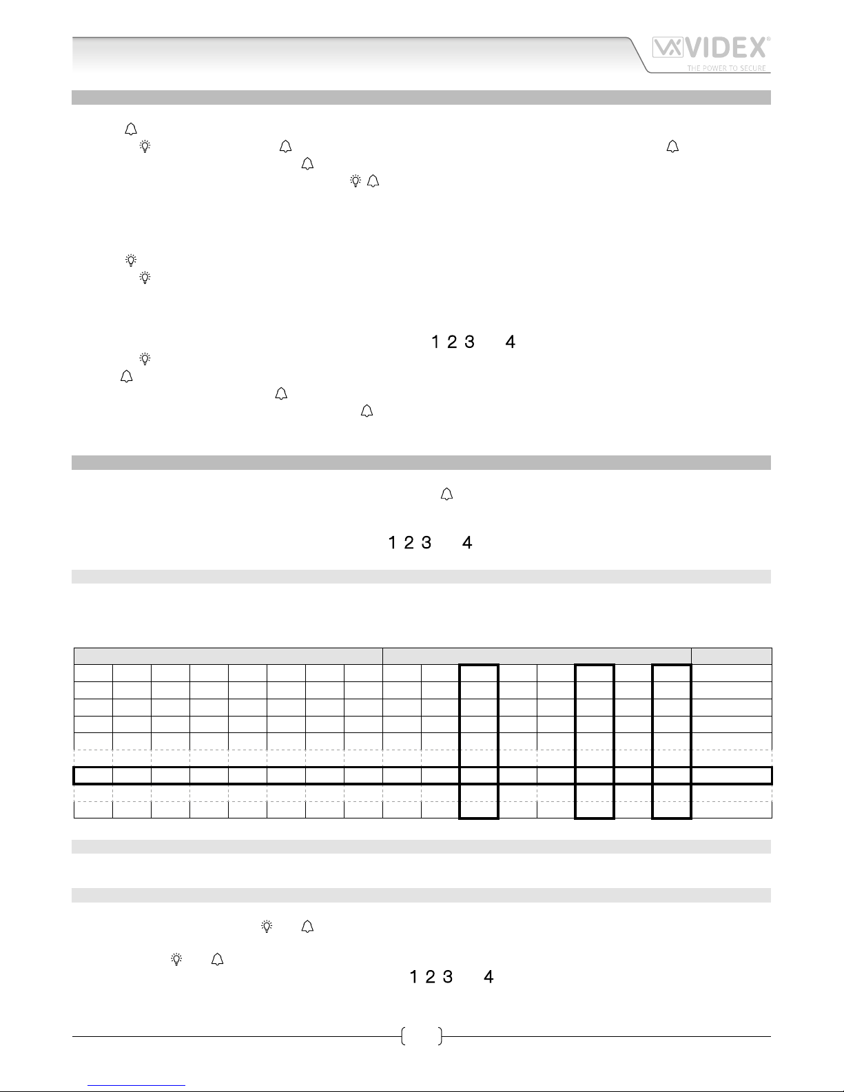
G
E
C
B
D
F
A
H
I
L
Fig. 1
DESCRIPTION
Digital audio/video door entry panel in the Kristallo design for indoor use only and to work with the
VIDEX VX2200 digital system.
Normally used on installations where each apartment requires an internal intercom directly outside
their apartment.
The panel includes an hd colour camera (650 lines with 90º of viewing angle) plus the illumination
LEDs (infrared light), the speaker unit module, one call button
, one service button and 4 nu-
meric buttons (
, , and ) for coded access using an eight digits code.
10 Way dip-switch bank of which 8 (1 to 8) are used to set the address of the videophone to call, the
nineth to set the door opening time (2 seconds = OFF, 6 seconds = ON) and the tenth to restore the
engineer’s code to factory default.
8 digit numeric access code programmable through the 4 numeric buttons.
Loudspeaker and microphone volume adjustable through two trimmers on the bottom of the unit.
Block exchangers are not required.
PUSH BUTTONS
Call button
Press to call the videophone with same PHONE
ID programmed on the 10 way dip-switch bank.
Stairs light button
Press to enable the relevant “LGT” active low
open collector output (Maximum 100mA). Normally used as stair light button (a specic connection is requested to operate).
Code buttons
Press to enter the door opening code and activate the relevant “REL” active low open collector
output (Maximum 100mA). Use the same button also to program the door opening code (a
specic connection is requested to operate the
door opening code).
LEDS
Camera IR LEDs
Provide the camera illumination during the call
and the conversation.
Stairway lighting LED
Normally turned ON during the standby, temporarily ashes quickly when the relevant button
is pressed.
When the unit is in door open code programming mode, the LED ashes quickly.
Call LED
Normally turned ON during the standby, temporarily ashes slowly (during the call or conversation) when the relevant button is pressed .
When the unit it is in door open code programming mode, the LED ashes quickly.
LEGEND
A
Microphone
B
Camera IR LEDs
C
Colour Camera
D
Stairway lighting LED
E
Stairway lighting button
F
Call LED
G
Call button
H
Push buttons
I
Connection Terminals
L
Dip Switch
M
Microphone &
loudspeaker trimmer
Art.KR-AV Indoor Digital A/V door panel for VX2200
M
Page 2
66250935-EN - V1.2 - 15/01/16
2
Kristallo Series
Art.KR-AV - Installation instructions
OPERATION
To call the apartment
Press the
button :
• The LED
turns OFF and the LED starts ashing slowly emitting a low volume beep each time the LED turns ON.
• When the apartment answers, the LED
ashes faster and the conversation is open.
• When the conversation is closed, both the LEDs
are temporarily turned OFF then turned ON again.
In case of no answer, the call stops automatically after 40 seconds approx while in case of answer if the conversation is not closed
by the user the call will terminate automatically after 60 seconds.
To switch ON the stair light
Press the
button :
• The LED
ashes quickly during the time that the “LGT” output is active.
The function requires the connection of a relay that must be enabled by the “LGT” active low output.
To open the door by the door open code
Enter the 8 digits door opening code by the four numeric buttons
, , and .
• The LED
turns o.
The LED
turns o then the unit emits a beep and the LED ashes each time a numeric button is pressed.
If the entered code is correct, the LED
ashes quickly 3 times, the unit emits 3 short beeps and the “REL” output is enabled for the
programmed time while if the code is wrong the LED
remains o and 3long beep are emitted.
The function requires the connection of a relay that must be enabled by the “REL” active low output.
PROGRAMMING & ADJUSTMENTS
Programming options are:
• The Phone ID (address) of the local videophone to call when the
button is pressed (10 ways dip-switch bank, switches from
1 to 8).
• The door opening time for the electric lock (switch 9).
• The door opening code (through the numeric buttons
, , and ).
LOCAL VIDEOPHONE PHONE ID SETUP
Use the rst 8 dip-switches of the 10 way dip-switch bank to set the PHONE ID for the local videophone. Each switch corresponds to
one bit which can have a value 0 (OFF) or 1 (ON). Each bit corresponds to a decimal weight depending on the position: Switch 1 =
decimal 1, 2=2, 3=4, 4=8, 5=16, 6=32, 7=64, 8=128. I.E. to set the address 37, put switches 1, 3 and 6 on (1+4+32=37).
SWITCHES DECIMAL WEIGHT ADDRESS
8 7 6 5 4 3 2 1 128 64 32 16 8 4 2 1
OFF OFF OFF OFF OFF OFF OFF ON 0 0 0 0 0 0 0 1 1
OFF OFF OFF OFF OFF OFF ON OFF 0 0 0 0 0 0 1 0 2
OFF OFF OFF OFF OFF OFF ON ON 0 0 0 0 0 0 1 1 3
OFF OFF OFF OFF OFF ON OFF OFF 0 0 0 0 0 1 0 0 4
OFF OFF ON OFF OFF ON OFF ON 0 0 1 0 0 1 0 1 37
ON OFF ON ON OFF ON OFF OFF 1 0 1 1 0 1 0 0 180
DOOR OPENING TIME SETUP
The switch 9 sets the door opening time : OFF= 2 seconds, ON= 6 seconds.
DOOR OPEN CODE SETUP
To setup the door opening code proceed as follows:
1. With the unit in stand-by (LEDs
and ) turned ON, enter the 8 digit engineer’s code (factory default “11111111” eight times
one).
2. Both the LEDs
and start ashing, enter a new engineer’s code (8 digits) or conrm the old one entering it (8 digits) again.
3. Enter the new door open code (8 digits) using the buttons
, , and .
To restore the engineer’s code to the factory default, power o the unit put ON switch 10 and power up the unit again then
put OFF switch 10. The engineer’s code is restored to “11111111” eight times one.
Art.KR-AV Indoor Digital A/V door panel for VX2200
Page 3
66250935-EN - V1.2 - 15/01/16
3
Kristallo Series
Art.KR-AV - Installation instructions
Art.KR-AV Indoor Digital A/V door panel for VX2200
VOLUME ADJUSTMENT
Volume adjustment trimmers are available for both microphone and speaker and are located at the bottom of the unit.
(Fig. 1 reference “M”).
ELECTRIC LOCK CONNECTION
REL
LGT
V1-O
V2-O
V1-I
V2-I
L-O
L-I
Gnd
12V
NC2
4
C01
NC1
NO1
CO2
1
2
3
Art.506N
NO2
5
SE
12Vac
Fig. 2
TERMINALS
REL
Open collector active low output Vdc 100mA max enabled by door opening code (
, , and buttons)
LGT
Open collector active low output Vdc 100mA max enabled by
button
V1-O Video signal V1 output toward the local videophone
V2-O Video signal V2 output toward the local videophone
V1-I Video signal V1 input from the main rising column
V2-I Video signal V2 input from the main rising column
L-O Data BUS out toward the local videophone
L-I Data BUS in from the main rising column
Gnd 12Vdc power supply ground and Data BUS minus connection
12V 12Vdc power supply input
TECHNICAL SPECIFICATION
Power supply voltage: 12÷14Vdc
Power consumption: Stand-by: 6mA max (on 12Vdc)
Operating: 200mA Max (on 12Vdc)
Working temperature: -10° +50° C
Page 4

Videx Electronics S.p.A.
Via del Lavoro 1, 63846 Monte Giberto (FM)
Phone: +39 0734 631669 - Fax +39 0734 631669
www.videx.it - info@videx.it
Autore:
Data modifica:
Data creazione:Title:
Notes:
Titolo:
Note:
Cod.File:
Foglio
/
26/11/2015
19/12/2014
s
p
2200wd25d.dw
g
Marco Rongoni
11
ON/OFF
+
13V
ART.521B
115
0
swsw
+B
B.V.
coax
others
316x
Art.4202RV
A
SE
12Vac
MAIN MODE
REL
LGT
V1-O
V2-O
V1-I
V2-I
L-O
L-I
Gnd
12V
NC2
4
C01
NC1
NO1
CO2
1
2
3
Art.506N
NO2
5
Art.KRV78
Address N. 1
Art.KRV78
SE
12Vac
KR-AV
Gnd-L
L
V1V2
REL
LGT
V1-O
V2-O
V1-I
V2-I
L-O
L-I
Gnd
12V
NC2
4
C01
NC1
NO1
CO2
1
2
3
Art.506N
NO2
5
Art.KRV78
Address N. 2
Art.KRV78
SE
12Vac
KR-AV
4
Art.KR-AV Digital A/V door panel for VX2200
Page 5

66250935-EN - V1.0 - 04/05/15
5
Kristallo Series
Art.KR-AV - Installation instructions
Art.KR-AV mounting instructions
135cm
Fig. 1
Fig. 3
Fig. 2
Fig. 4
1. Protect the holes to x the intercom to the ush mounting box then embed the ush mounting box in line with the wall in vertical
position at 135cm height from the oor as shown in Fig. 1;
2. As shown in Fig. 2, connect the wires using a at screw driver then setup the dip-switches as per provided connection diagram
or instruction sheet.
3. As shown in Fig. 3, once the wires are connected, x the intercom to the ush mounting box using a Phillips screwdriver and the
two screws provided.
In order to avoid malfunctions, please do not over tighten the xing screws shown in Fig. 3.
4. Once the intercom is xed to the ush mounting box, place the front plate against the intercom by inserting the hooks in the
corresponding openings and hook the plate by pushing it down as shown in Fig. 4.
5. Test the system for correct operation.
Page 6

6
1 2 3 4 5 6 7 8
ON
1
1 2 3 4 5 6 7 8
ON
2
1 2 3 4 5 6 7 8
ON
3
1 2 3 4 5 6 7 8
ON
4
1 2 3 4 5 6 7 8
ON
5
1 2 3 4 5 6 7 8
ON
6
1 2 3 4 5 6 7 8
ON
7
1 2 3 4 5 6 7 8
ON
8
1 2 3 4 5 6 7 8
ON
9
1 2 3 4 5 6 7 8
ON
10
1 2 3 4 5 6 7 8
ON
11
1 2 3 4 5 6 7 8
ON
12
1 2 3 4 5 6 7 8
ON
13
1 2 3 4 5 6 7 8
ON
14
1 2 3 4 5 6 7 8
ON
15
1 2 3 4 5 6 7 8
ON
16
1 2 3 4 5 6 7 8
ON
17
1 2 3 4 5 6 7 8
ON
18
1 2 3 4 5 6 7 8
ON
19
1 2 3 4 5 6 7 8
ON
20
1 2 3 4 5 6 7 8
ON
21
1 2 3 4 5 6 7 8
ON
22
1 2 3 4 5 6 7 8
ON
23
1 2 3 4 5 6 7 8
ON
24
1 2 3 4 5 6 7 8
ON
25
1 2 3 4 5 6 7 8
ON
26
1 2 3 4 5 6 7 8
ON
27
1 2 3 4 5 6 7 8
ON
28
1 2 3 4 5 6 7 8
ON
29
1 2 3 4 5 6 7 8
ON
30
1 2 3 4 5 6 7 8
ON
31
1 2 3 4 5 6 7 8
ON
32
1 2 3 4 5 6 7 8
ON
33
1 2 3 4 5 6 7 8
ON
34
1 2 3 4 5 6 7 8
ON
35
1 2 3 4 5 6 7 8
ON
36
1 2 3 4 5 6 7 8
ON
37
1 2 3 4 5 6 7 8
ON
38
1 2 3 4 5 6 7 8
ON
39
1 2 3 4 5 6 7 8
ON
40
1 2 3 4 5 6 7 8
ON
41
1 2 3 4 5 6 7 8
ON
42
1 2 3 4 5 6 7 8
ON
43
1 2 3 4 5 6 7 8
ON
44
1 2 3 4 5 6 7 8
ON
45
1 2 3 4 5 6 7 8
ON
46
1 2 3 4 5 6 7 8
ON
47
1 2 3 4 5 6 7 8
ON
48
1 2 3 4 5 6 7 8
ON
49
1 2 3 4 5 6 7 8
ON
50
1 2 3 4 5 6 7 8
ON
51
1 2 3 4 5 6 7 8
ON
52
1 2 3 4 5 6 7 8
ON
53
1 2 3 4 5 6 7 8
ON
54
1 2 3 4 5 6 7 8
ON
55
1 2 3 4 5 6 7 8
ON
56
1 2 3 4 5 6 7 8
ON
57
1 2 3 4 5 6 7 8
ON
58
1 2 3 4 5 6 7 8
ON
59
1 2 3 4 5 6 7 8
ON
60
1 2 3 4 5 6 7 8
ON
61
1 2 3 4 5 6 7 8
ON
62
1 2 3 4 5 6 7 8
ON
63
1 2 3 4 5 6 7 8
ON
64
1 2 3 4 5 6 7 8
ON
65
1 2 3 4 5 6 7 8
ON
66
1 2 3 4 5 6 7 8
ON
67
1 2 3 4 5 6 7 8
ON
68
1 2 3 4 5 6 7 8
ON
69
1 2 3 4 5 6 7 8
ON
70
1 2 3 4 5 6 7 8
ON
71
1 2 3 4 5 6 7 8
ON
72
1
2 3 4 5 6 7 8
ON
73
1 2 3 4 5 6 7 8
ON
74
1 2 3 4 5 6 7 8
ON
75
1 2 3 4 5 6 7 8
ON
76
1 2 3 4 5 6 7 8
ON
77
1 2 3 4 5 6 7 8
ON
78
1 2 3 4 5 6 7 8
ON
79
1 2 3 4 5 6 7 8
ON
80
1 2 3 4 5 6 7 8
ON
81
1 2 3 4 5 6 7 8
ON
82
1 2 3 4 5 6 7 8
ON
83
1 2 3 4 5 6 7 8
ON
84
1 2 3 4 5 6 7 8
ON
85
1 2 3 4 5 6 7 8
ON
86
1 2 3 4 5 6 7 8
ON
87
1 2 3 4 5 6 7 8
ON
88
1 2 3 4 5 6 7 8
ON
89
1 2 3 4 5 6 7 8
ON
90
1 2 3 4 5 6 7 8
ON
91
1 2 3 4 5 6 7 8
ON
92
1 2 3 4 5 6 7 8
ON
93
1 2 3 4 5 6 7 8
ON
94
1 2 3 4 5 6 7 8
ON
95
1 2 3 4 5 6 7 8
ON
96
1 2 3 4 5 6 7 8
ON
97
1 2 3 4 5 6 7 8
ON
98
1 2 3 4 5 6 7 8
ON
99
1 2 3 4 5 6 7 8
ON
100
1 2 3 4 5 6 7 8
ON
101
1 2 3 4 5 6 7 8
ON
102
1 2 3 4 5 6 7 8
ON
103
1 2 3 4 5 6 7 8
ON
104
1 2 3 4 5 6 7 8
ON
105
1 2 3 4 5 6 7 8
ON
106
1 2 3 4 5 6 7 8
ON
107
1 2 3 4 5 6 7 8
ON
108
1 2 3 4 5 6 7 8
ON
109
1 2 3 4 5 6 7 8
ON
110
1 2 3 4 5 6 7 8
ON
111
1 2 3 4 5 6 7 8
ON
112
1 2 3 4 5 6 7 8
ON
113
1 2 3 4 5 6 7 8
ON
114
1 2 3 4 5 6 7 8
ON
115
1 2 3 4 5 6 7 8
ON
116
1 2 3 4 5 6 7 8
ON
117
1 2 3 4 5 6 7 8
ON
118
1 2 3 4 5 6 7 8
ON
119
1 2 3 4 5 6 7 8
ON
120
1 2 3 4 5 6 7 8
ON
121
1 2 3 4 5 6 7 8
ON
122
1 2 3 4 5 6 7 8
ON
123
1 2 3 4 5 6 7 8
ON
124
1 2 3 4 5 6 7 8
ON
125
1 2 3 4 5 6 7 8
ON
126
1 2 3 4 5 6 7 8
ON
127
1/2
= OFF
= ON
Addresses 1..127 Table for dip-switch banks with ON position up
Page 7

7
1 2 3 4 5 6 7 8
ON
128
1 2 3 4 5 6 7 8
ON
129
1 2 3 4 5 6 7 8
ON
130
1 2 3 4 5 6 7 8
ON
131
1 2 3 4 5 6 7 8
ON
132
1 2 3 4 5 6 7 8
ON
133
1 2 3 4 5 6 7 8
ON
134
1 2 3 4 5 6 7 8
ON
135
1 2 3 4 5 6 7 8
ON
136
1 2 3 4 5 6 7 8
ON
137
1 2 3 4 5 6 7 8
ON
138
1 2 3 4 5 6 7 8
ON
139
1 2 3 4 5 6 7 8
ON
140
1 2 3 4 5 6 7 8
ON
141
1 2 3 4 5 6 7 8
ON
142
1 2 3 4 5 6 7 8
ON
143
1 2 3 4 5 6 7 8
ON
144
1 2 3 4 5 6 7 8
ON
145
1 2 3 4 5 6 7 8
ON
146
1 2 3 4 5 6 7 8
ON
147
1 2 3 4 5 6 7 8
ON
148
1 2 3 4 5 6 7 8
ON
149
1 2 3 4 5 6 7 8
ON
150
1 2 3 4 5 6 7 8
ON
151
1 2 3 4 5 6 7 8
ON
152
1 2 3 4 5 6 7 8
ON
153
1 2 3 4 5 6 7 8
ON
154
1 2 3 4 5 6 7 8
ON
155
1 2 3 4 5 6 7 8
ON
156
1 2 3 4 5 6 7 8
ON
157
1 2 3 4 5 6 7 8
ON
158
1 2 3 4 5 6 7 8
ON
159
1 2 3 4 5 6 7 8
ON
160
1 2 3 4 5 6 7 8
ON
161
1 2 3 4 5 6 7 8
ON
162
1 2 3 4 5 6 7 8
ON
163
1 2 3 4 5 6 7 8
ON
164
1 2 3 4 5 6 7 8
ON
165
1 2 3 4 5 6 7 8
ON
166
1 2 3 4 5 6 7 8
ON
167
1 2 3 4 5 6 7 8
ON
168
1 2 3 4 5 6 7 8
ON
169
1 2 3 4 5 6 7 8
ON
170
1 2 3 4 5 6 7 8
ON
171
1 2 3 4 5 6 7 8
ON
172
1 2 3 4 5 6 7 8
ON
173
1 2 3 4 5 6 7 8
ON
174
1 2 3 4 5 6 7 8
ON
175
1 2 3 4 5 6 7 8
ON
176
1 2 3 4 5 6 7 8
ON
177
1 2 3 4 5 6 7 8
ON
178
1 2 3 4 5 6 7 8
ON
179
1 2 3 4 5 6 7 8
ON
180
1 2 3 4 5 6 7 8
ON
181
1 2 3 4 5 6 7 8
ON
182
1 2 3 4 5 6 7 8
ON
183
1 2 3 4 5 6 7 8
ON
184
1 2 3 4 5 6 7 8
ON
185
1 2 3 4 5 6 7 8
ON
186
1 2 3 4 5 6 7 8
ON
187
1 2 3 4 5 6 7 8
ON
188
1 2 3 4 5 6 7 8
ON
189
1 2 3 4 5 6 7 8
ON
190
1 2 3 4 5 6 7 8
ON
191
1 2 3 4 5 6 7 8
ON
192
1 2 3 4 5 6 7 8
ON
193
1 2 3 4 5 6 7 8
ON
194
1 2 3 4 5 6 7 8
ON
195
1 2 3 4 5 6 7 8
ON
196
1 2 3 4 5 6 7 8
ON
197
1 2 3 4 5 6 7 8
ON
198
1 2 3 4 5 6 7 8
ON
199
1 2 3 4 5 6 7 8
ON
200
1 2 3 4 5 6 7 8
ON
201
1 2 3 4 5 6 7 8
ON
202
1 2 3 4 5 6 7 8
ON
203
1 2 3 4 5 6 7 8
ON
204
1 2 3 4 5 6 7 8
ON
205
1 2 3 4 5 6 7 8
ON
206
1 2 3 4 5 6 7 8
ON
207
1 2 3 4 5 6 7 8
ON
208
1 2 3 4 5 6 7 8
ON
209
1 2 3 4 5 6 7 8
ON
210
1 2 3 4 5 6 7 8
ON
211
1 2 3 4 5 6 7 8
ON
212
1 2 3 4 5 6 7 8
ON
213
1 2 3 4 5 6 7 8
ON
214
1 2 3 4 5 6 7 8
ON
215
1 2 3 4 5 6 7 8
ON
216
1 2 3 4 5 6 7 8
ON
217
1 2 3 4 5 6 7 8
ON
218
1 2 3 4 5 6 7 8
ON
219
1 2 3 4 5 6 7 8
ON
220
1 2 3 4 5 6 7 8
ON
221
1 2 3 4 5 6 7 8
ON
222
1 2 3 4 5 6 7 8
ON
223
1 2 3 4 5 6 7 8
ON
224
1 2 3 4 5 6 7 8
ON
225
1 2 3 4 5 6 7 8
ON
226
1 2 3 4 5 6 7 8
ON
227
1 2 3 4 5 6 7 8
ON
228
1 2 3 4 5 6 7 8
ON
229
1 2 3 4 5 6 7 8
ON
230
1 2 3 4 5 6 7 8
ON
231
1 2 3 4 5 6 7 8
ON
232
1 2 3 4 5 6 7 8
ON
233
1 2 3 4 5 6 7 8
ON
234
1 2 3 4 5 6 7 8
ON
235
1 2 3 4 5 6 7 8
ON
236
1 2 3 4 5 6 7 8
ON
237
1 2 3 4 5 6 7 8
ON
238
1 2 3 4 5 6 7 8
ON
239
1 2 3 4 5 6 7 8
ON
240
1 2 3 4 5 6 7 8
ON
241
1 2 3 4 5 6 7 8
ON
242
1 2 3 4 5 6 7 8
ON
243
1 2 3 4 5 6 7 8
ON
244
1 2 3 4 5 6 7 8
ON
245
1 2 3 4 5 6 7 8
ON
246
1 2 3 4 5 6 7 8
ON
247
1 2 3 4 5 6 7 8
ON
248
1 2 3 4 5 6 7 8
ON
249
1 2 3 4 5 6 7 8
ON
250
1 2 3 4 5 6 7 8
ON
251
1 2 3 4 5 6 7 8
ON
252
1 2 3 4 5 6 7 8
ON
253
1 2 3 4 5 6 7 8
ON
254
1 2 3 4 5 6 7 8
ON
255
2/2
= OFF
= ON
Addresses 128..255 Table for dip-switch banks with ON position up
Page 8

MANUFACTURER
VIDEX ELECTRONICS S.P.A.
Via del Lavoro, 1 - 63846 Monte Giberto (FM) Italy
Tel (+39) 0734 631669 - Fax (+39) 0734 632475
www.videx.it - info@videx.it
CUSTOMER SUPPORT
All Countries:
VIDEX ELECTRONICS S.P.A.
www.videx.it - technical@videx.it
Tel: +39 0734-631669 - Fax: +39 0734-632475
UK Customers:
VIDEX SECURITY LTD
www.videx-security.com
Tech Line: 0191 224 3174 - Fax: 0191 224 1559
The product is CE marked demonstrating its conformity and is for distribution
within all member states of the EU with no restrictions. This produc t follows
the provisions of the European Directives 2014/30/EU (EMC); 2014/35/EU
(LVD); 2011/65/EU (RoHS): CE marking 93/68/EEC.
Main UK oce:
VIDEX SECURITY LTD
1 Osprey Trinity Park
Trinity Way
LONDON E4 8TD
Phone: (+44) 0870 300 1240
Fax: (+44) 020 8523 5825
www.videx-security.com
marketing@videx-security.com
Northern UK oce:
VIDEX SECURITY LTD
Unit 4-7
Chillingham Industrial Estate
Chapman Street
NEWCASTLE UPON TYNE - NE6 2XX
Tech Line: (+44) 0191 224 3174
Phone: (+44) 0870 300 1240
Fax: (+44) 0191 224 1559
Greece oce:
VIDEX HELLAS Electronics
48 Filolaou Str.
11633 ATHENS
Phone: (+30) 210 7521028
(+30) 210 7521998
Fax: (+30) 210 7560712
www.videx.gr
videx@videx.gr
Danish oce:
VIDEX DANMARK
Hammershusgade 15
DK-2100 COPENHAGEN
Phone: (+45) 39 29 80 00
Fax: (+45) 39 27 77 75
www.videx.dk
videx@videx.dk
Benelux oce:
VIDEX BENELUX
E3 Iaan, 93
B-9800 DEINZE
Phone: (+32) 9 380 40 20
Fax: (+32) 9 380 40 25
www.videxbenelux.be
info@videxbenelux.be
 Loading...