

Page 1
66550060-EN
V1.0
06/02/14
by VIDEX
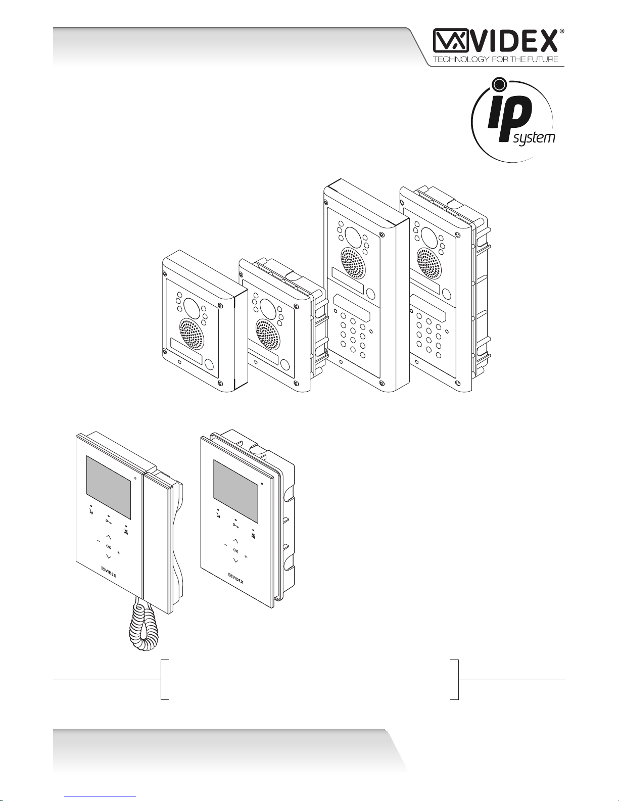
VIDEOKIT
IPVKKRISTALLO SERIES
IP One way, two way videokit
IPVK
IPVKC
KRISTALLO
Installation handbook
Page 2

66550060-EN - V1.0 - 06/02/14
2
IPVK - IPVKC Series IP videokit
IPVK-IPVKC - Installation handbook
Introduction
INTRODUCTION
The information in this manual is intended as an installation and commissioning guide for the IP door intercom system. This manual
should be read carefully before the installation commences. Any damage caused to the equipment due to faulty installations where
the information in this manual has not been followed is not the responsibility of Videx Electronics S.p.A.
SYSTEM INTRODUCTION
Systems employing IP technology are becoming more and more popular and giving their widespread use Videx has developed a
door entry system encompassing this technology. After more than 2 years of research and development, Videx introduces the first
line of IP products, including colour camera speaker modules for the 4000 Series and IP videophones in the Kristallo Series.
Thanks to the IP technology, communication between devices can be made both locally via a LAN or private network or remotely
using LAN and WAN. With the integration of the SIP protocol as standard it is also possible to connect the Videx door stations to third
party telephone systems which also support the SIP protocol. WiFi can also be used to communicate with tablets and smart phones
running the Android operating system, a PC soft phone is also available. The 4000 Series style door panels can be customised from
1 – 64 call buttons and having a modular design enables other modules from the 4000 Series range to be integrated. Each button
can call up to 10 devices. The Kristallo videophones and video monitors are available in both a white and black finish and benefit
from touch controls and on screen programming. POE is also standard on the Kristallo enabling POE switches and routers to be used
to connect directly to the RJ45 connector on the device.
FEATURES
• Connect to Ethernet network (LAN, WAN or private network);
• SIP communication protocol included;
• Integrated web server for configu ation;
• Up to 66 call buttons;
• 2 output relays with dry contacts;
• 1 Push to exit active low input;
• Can be used as standard VOIP device where SIP is already used;
• Modular system integrated in VIDEX 4000 Series;
• DTMF according to the standard RCF2833, in band;
Page 3
66550060-EN - V1.0 - 06/02/14
3
IPVK - IPVKC Series IP videokit
IPVK-IPVKC - Installation handbook
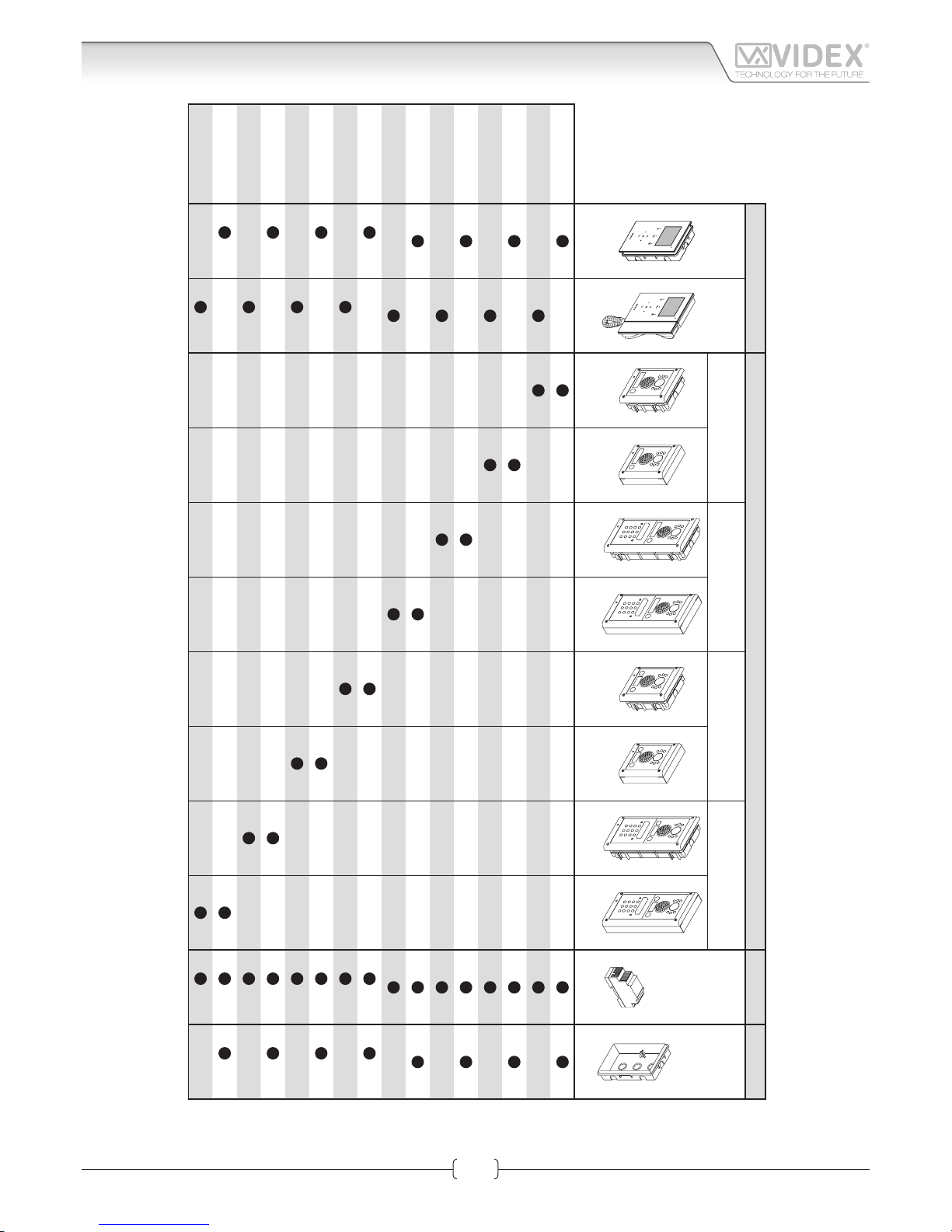
System components
Indoor stations
Outdoor stations
Power supply
Accessories
One way
One way
with codelock
Two way
Two way
with codelock
Art.AMR2-12
Art.KRV981
flus surface flus surface flus surface flus surface flus surface
IPVK-1/98
IPVK-1/96
IPVK-1S/98
IPVK-1S/96
IPVKC-1/98
IPVKC-1/96
IPVKC-1S/98
IPVKC-1S/96
IPVK-2/98
x2 x2 x2
IPVK-2/96
x2 x2
IPVK-2S/98
x2 x2 x2
IPVK-2S/96
x2 x2
IPVKC-2/98
x2 x2 x2
IPVKC-2/96
x2 x2
IPVKC-2S/98
x2 x2 x2
IPVKC-2S/96
x2 x2
Page 4
66550060-EN - V1.0 - 06/02/14
4
IPVK - IPVKC Series IP videokit
IPVK-IPVKC - Installation handbook
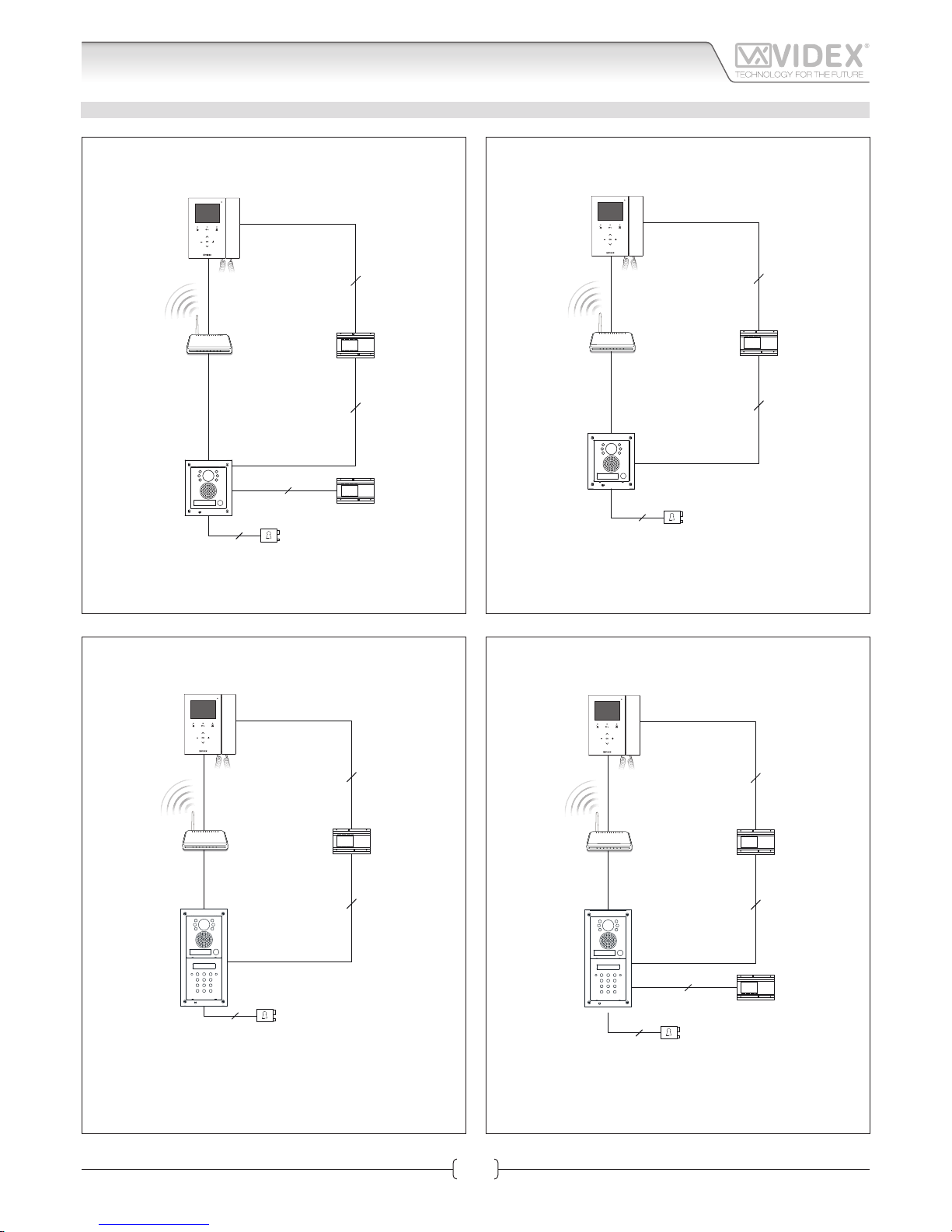
ONE WAY INSTALLATION DIAGRAMS
2
2
2
2
Ethernet Cable
Ethernet Cable
Standard or
Wi-Fi Router
AMR2-12
12Vdc Power Supply
Art.KRV96/98
IP Videophone
Art.4503
IP Door Panel
AC Electric Lock
Art.321
12Vac Power Supply
2
2
2
Ethernet cable
Ethernet cable
Standard or
Wi-Fi Router
AMR2-12
12Vdc Power supply
Art.KRV96/98
IP videophone
Art.4503
IP door panel
DC electric lock
2
2
2
Ethernet cable
Ethernet cable
Standard or
Wi-Fi Router
AMR2-12
12Vdc Power supply
Art.KRV96/98
IP videophone
DC electric lock
Art.4503
IP door panel
Art.4800
Digital Codelock
2
2
2
2
Ethernet Cable
Ethernet Cable
Standard or
Wi-Fi Router
AMR2-12
12Vdc Power Supply
Art.KRV96/98
IP Videophone
AC Electric Lock
Art.321
12Vac Power Supply
Art.4503
IP door panel
Art.4800
Digital Codelock
Installation diagrams
Page 5
66550060-EN - V1.0 - 06/02/14
5
IPVK - IPVKC Series IP videokit
IPVK-IPVKC - Installation handbook
Installation diagrams
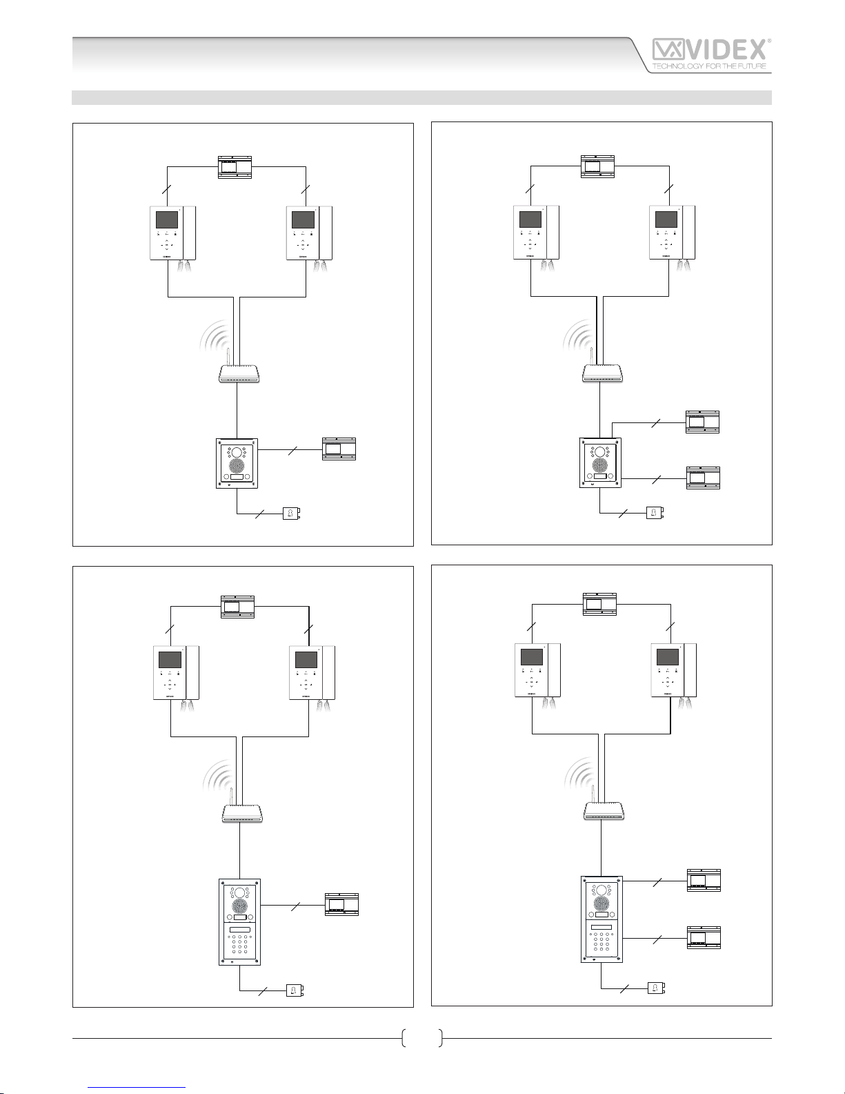
TWO WAY INSTALLATION DIAGRAMS
2
2
22
Ethernet cableEthernet cable
Ethernet cable
Standard or
Wi-Fi Router
AMR2-12
12Vdc Power supply
AMR2-12
12Vdc Power supply
Art.KRV96/98
IP videophone
Art.KRV96/98
IP videophone
Art.4503-1D
IP door panel
DC electric lock
2
2
22
2
Ethernet cableEthernet cable
Ethernet cable
Standard or
Wi-Fi Router
AMR2-12
12Vdc Power supply
AMR2-12
12Vdc Power supply
Art.KRV96/98
IP videophone
Art.KRV96/98
IP videophone
Art.4503-1D
IP door panel
AC electric lock
Art.321
12Vac Power supply
2
2
22
Ethernet cableEthernet cable
Ethernet cable
Standard or
Wi-Fi Router
AMR2-12
12Vdc Power supply
AMR2-12
12Vdc Power supply
Art.KRV96/98
IP videophone
Art.KRV96/98
IP videophone
Art.4503-1D
IP door panel
DC electric lock
Art.4800
Digital Codelock
2
2
22
2
Ethernet cableEthernet cable
Ethernet cable
Standard or
Wi-Fi Router
AMR2-12
12Vdc Power supply
AMR2-12
12Vdc Power supply
Art.321
12Vac Power supply
Art.KRV96/98
IP videophone
Art.KRV96/98
IP videophone
Art.4503-1D
IP door panel
AC electric lock
Art.4800
Digital Codelock
Page 6
66550060-EN - V1.0 - 06/02/14
6
IPVK - IPVKC Series IP videokit
IPVK-IPVKC - Installation handbook
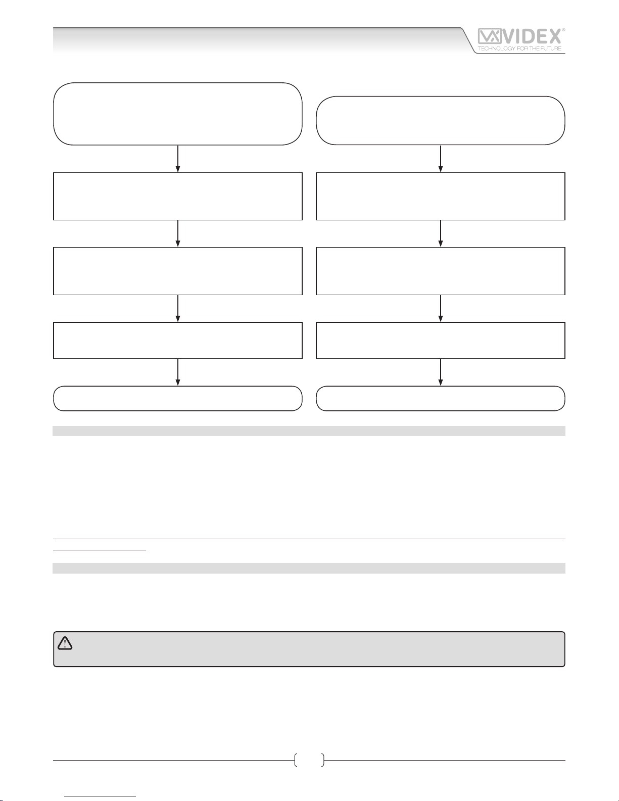
Connect the door panel as shown in “Power supply & connec-
tion” on page 9
Connect the videointercom as shown in “power supply & con-
nection” on page 25
Power up the system and execute the auto search procedure
from the videointercom as shown in section “Search” on page
41
The video door entry system is
ready to use
Verify that the preliminary ethernet LAN requirements are
satisfie .
See “LAN requirements for installation” on page 6
OPERATING THE VIDEOKIT
Open any internet browser then enter the IP address of the
videointercom/door panel
Navigate to the LAN settings page
see sections “Network parameters changes“ for Art.KRV98/96
on page 29 and for Art.4503 on page 14
Save the settings as required then wait for the unit to restart
The video door entry system is
now ready
Connect a PC (laptop or fi ed) to the existing LAN as shown
in section “Art.KRV98-KRV96 Hardware setup” on page 26
and “Art.4503 Hardware setup” on page 11
CHANGING THE VIDEOINTERCOM/DOOR PANEL
LAN SETTINGS
LAN REQUIREMENTS FOR INSTALLATION
The IP devices included in the kit can work when directly connected together but to use the services that require an internet connection it is better to connect the devices through an existing ethernet LAN.
The factory preset static IP addresses are:
Speaker unit module 192.168.1.3
Videointercom 1 (one way and two way videokits) 192.168.1.4
Videointercom 2 (two way videokits) 192.168.1.5
Before connecting the devices to an existing network check that the network address range is the same as the devices and that the
devices IP addresses are not already in use.
If the device’s addresses are in use or the range of network addresses is dierent, proceed to the section “IP devices - setup
procedure” on page 7.
CONNECTION TO MAINS
The system must be installed according to IEE and building regulations, in particular we recommend to:
• Connect the system to the mains through a double pole circuit breaker which shall have contact separation of at least 3mm in
each pole and shall disconnect both poles simultaneously;
• The double pole circuit breaker shall be placed for easy access and the switch shall remain readily operable.
ATTENTION
Fix the devices permanently to the wall only after testing the system.
Operating the videokit
Page 7
66550060-EN - V1.0 - 06/02/14
7
IPVK - IPVKC Series IP videokit
IPVK-IPVKC - Installation handbook
Operating the videokit
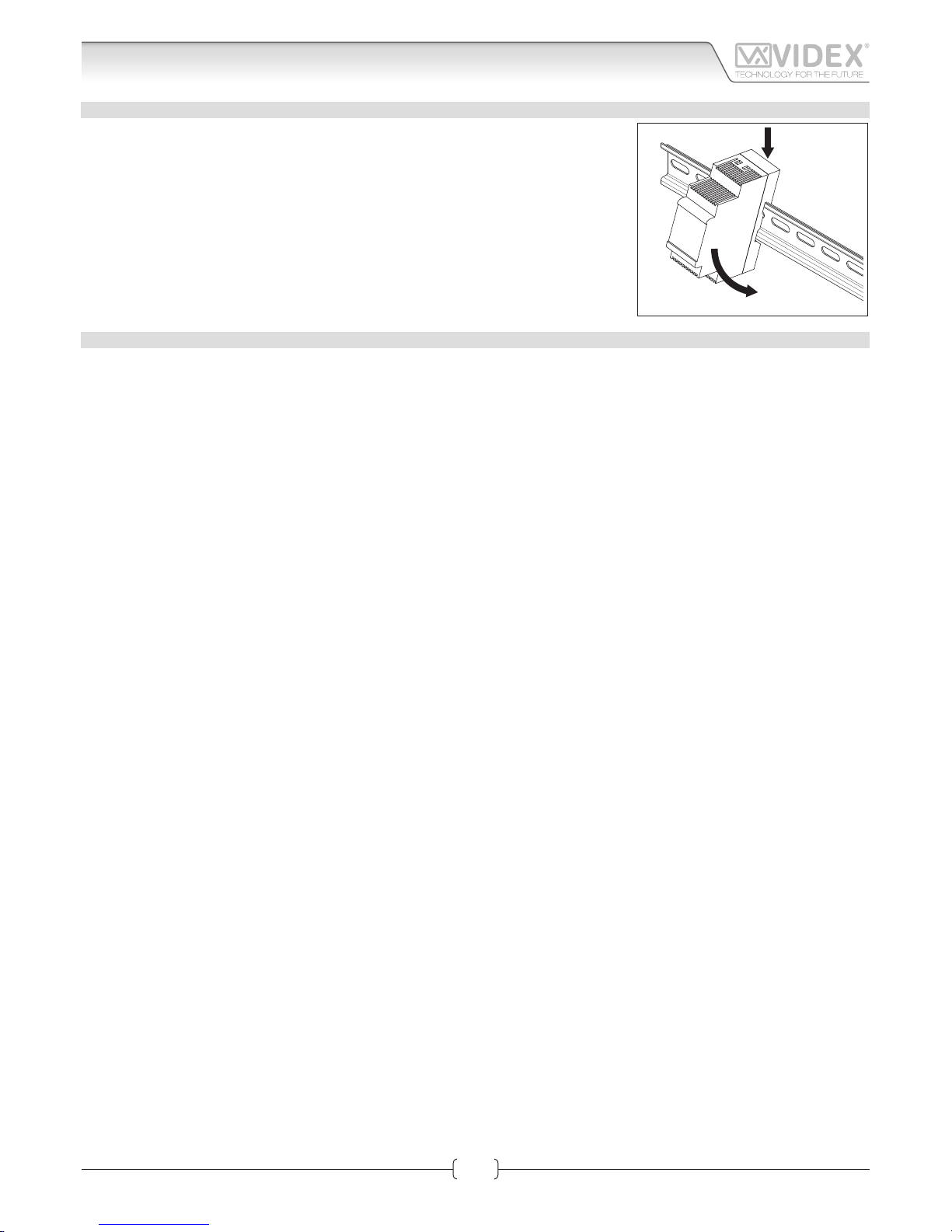
POWER SUPPLY INSTALLATION
• Fix the power supply to a DIN bar;
• Switch off the mains using the circuit breaker mentioned above and then make the
connections as shown on the installation diagrams;
• Check the connections and secure the wires into the terminals;
• Replace the terminal covers and secure them using the relevant screws;
• When all connections are made, restore the mains.
IP DEVICES SETUP PROCEDURE
SEE HARDWARE SETUP SECTIONS ON PAGES 11 AND 26 FOR MORE DETAIL
To change the setup of the IP devices you need to access to the devices internal web server from a web browser.
To access to the IP device’s web server, you need to know the devices IP address and the access credentials (user name and password).
If you have the information mentioned above and are able to connect to the device without changing the IP addresses and
setting then proceed to the section VIDEOINTERCOM (for videophone setup on page 26) or DOOR PANEL (for door panel
setup on page 11).
If the default IP addresses are not compatible with the network, follow the procedure below change these settings.
1. Using a PC (Laptop or desktop), manually change it’s IP address, subnet mask and gateway to the following:
a. Set the static IP address to 192.168.1.150;
b. Set the Subnet Mask to 255.255.255.0;
c. Set the Gateway to 192.168.1.1;
2. Power up the device: for the videointercom follow Fig. 5 in “power supply & connection” on page 25, for the speaker unit mod-
ule follow Fig. 3 or Fig. 4 in “Power supply & connection” on page 9;
3. Once the device is powered up, connect it to the PC either via a switch using patch cables or directly using a cross over cable. Open a
web browser on the PC enter one of the following addresses:
a. Enter the address “http://192.168.1.3” if you are setting up the speaker unit module (IP Videokit one way and two way) then
follow the instructions shown in the DOOR PANEL section;
b. Enter the address “http://192.168.1.4” if you are setting up the videointercom “1” (IP Videokit one way and two way) then
follow the instructions shown in the VIDEO INTERCOM section;
c. Enter the address “http://192.168.1.5” if you are setting up the videointercom “2” (IP Videokit two way) then follow the in-
structions shown the VIDEO INTERCOM section;
4. Remember to save the new setting before exiting then follow the procedure to connect the devices to the network.
Page 8
66550060-EN - V1.0 - 06/02/14
8
Fig. 1
4503-0
4503-1
4503-1D
Stainless Steel
Aluminium
High Brass
green / verde
green-white / verde-bianco
orange / arancione
orange-white / arancione-bianco
GND
PTE
Not
Used
0Vdc
+12Vdc
Made in Italy
RX - RS-232
TX - RS-232
GND
From
Art.4513
Day/Night
Infrared LED
Colour Camera
NETWORK SETTINGS DEFAULT
IP ADDRESS: _____ . _____ . _____ . _____ (192.168.1.3)
SUBNET MASK: _____ . _____ . _____ . _____ (255.255.255.0)
GATEWAY: _____ . _____ . _____ . _____ (192.168.1.1)
TIA/EIA-568-B.1-2001 T568B
Wiring
Green
Green / WhiteOrange
Orange / White
Orange / White
Orange
Green / White
Blue
Blue / White
Green
Brown / White
Brown
Fig. 2
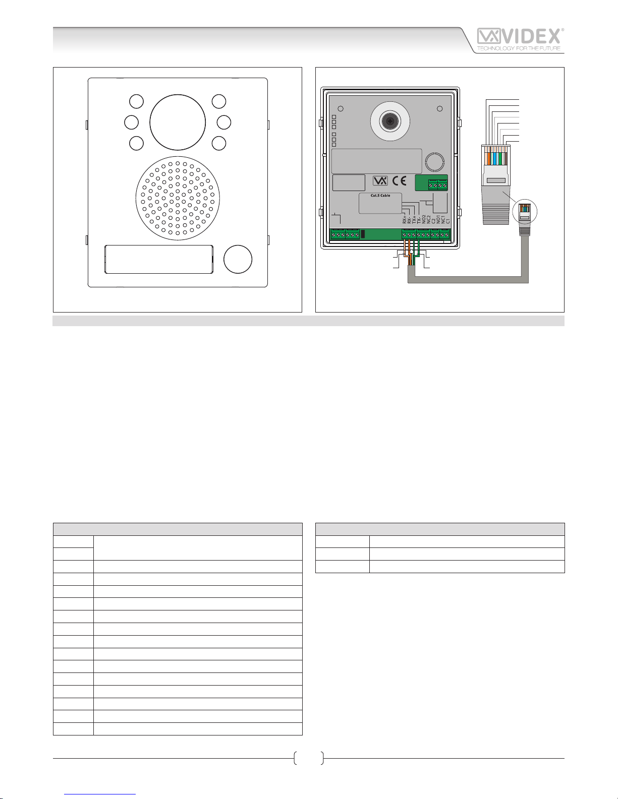
DESCRIPTION
The 4000 Series IP video speaker unit module can be used with any VIDEX IP device or any computer using a specific MS-Windows Client or any
smartphone/tablet using a specific Android client. It is available in a 0, 1 or 2 button version but for installation with more than 2 call buttons can
be used in combination with the special interface module Art.4513 that enables the connection of up to 64 additional buttons using conventional
button expansion modules.
• Videx 4000 Series modular system;
• 10/100 Mbit Ethernet interface;
• Compatible with SIP protocol (it can be connected with VOIP switchboard systems);
• It recognizes DTMF tones complying with RFC2833 specific tion;
• In built web server to set operation parameters;
• Possibility to connect up to 66 call buttons (an interface module is required to which it is possible to connect standard expansion modules
from the 4000 Series);
• 2 dry contact relay outputs (C, NC, NO) with programmable operation times;
• 1 “active low” input for “push to exit” button;
• It is possible to set up to 10 IP addresses or SIP ID’s for each call button;
• Client to be used with a PC using MS Windows operating system;
• Client to be used with a tablet and smartphone using Android operation system;
• Firmware can be updated through a web server;
• A wide angle camera is also available.
TERMINALS
L
Not used
H
+12Vdc 12Vdc - 500mA Power supply input
0Vdc Power Supply Ground
GND Ground
PTE “Push to Exit” active low input
RX+ CAT5 cable Orange/white wire
RX– CAT5 cable Orange wire
TX+ CAT5 cable Green/white wire
TX– CAT5 cable Green wire
NO2 Relay 2 normally open contact
NC2 Relay 2 normally closed contact
C2 Relay 2 common contact
NO1 Relay 1 normally open contact
NC1 Relay 1 normally closed contact
C1 Relay 1 common contact
TERMINALS TO ART.4513
RX-RS-232 RS-232 Connection RX signal
TX-RS-232 RS-232 Connection TX signal
GND Ground
Art.4503 IP Video Speaker Unit Module
Connection
IPVK - IPVKC Series IP videokit
IPVK-IPVKC - Installation handbook
Page 9
66550060-EN - V1.0 - 06/02/14
9
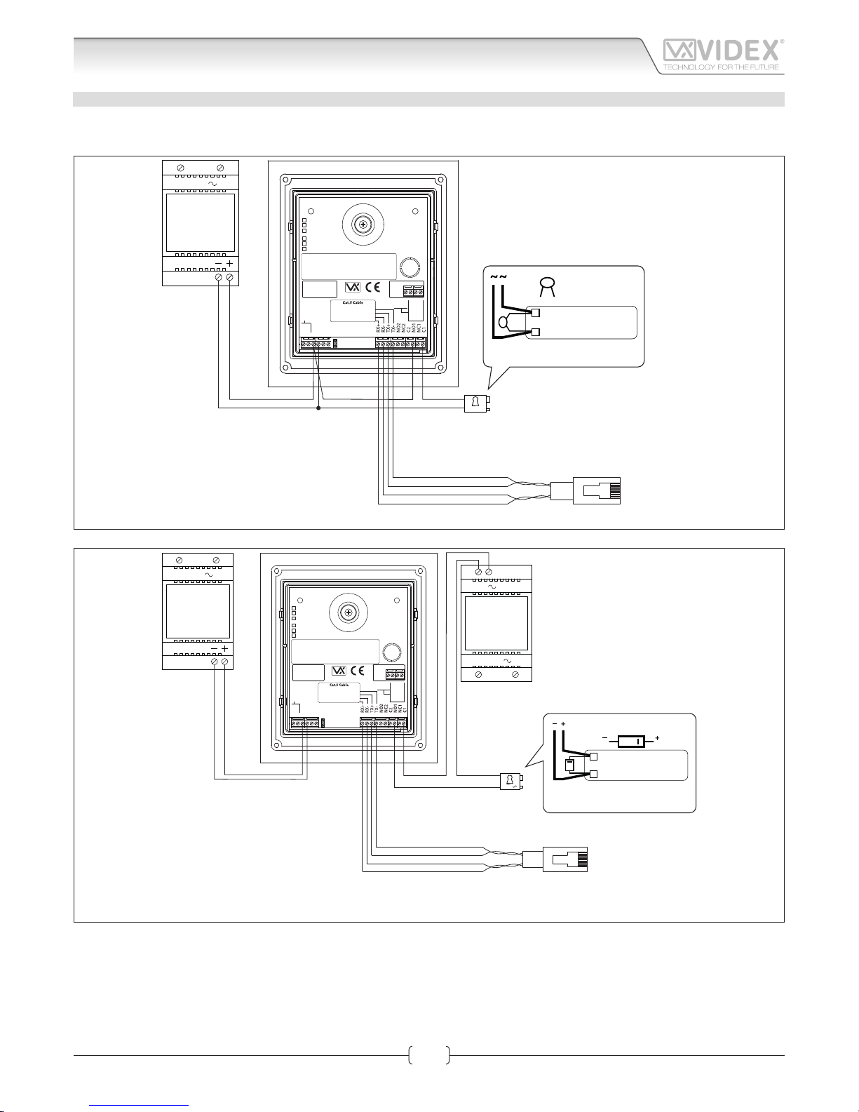
POWER SUPPLY & CONNECTION
For 12Vdc electric lock, follow the connections shown in Fig. 3 otherwise, for 12Vac electric lock, follow the connections shown in
Fig. 4. When you use a 12Vac electric lock, it is necessary to install an additional power supply not provided with the kit.
230V
12Vdc
Art.AMR2-12
or
12Vdc 2A
PSU
12Vdc
4503-0
4503-1
4503-1D
Stainless Steel
Aluminium
High Brass
green / verde
green-white / verde-bianco
orange / arancione
orange-white / arancione-bianco
GND
PTE
Not
Used
0Vdc
+12Vdc
Made in Italy
RX - RS-232
TX - RS-232
GND
From
Art.4513
Day/Night
Infrared LED
Colour Camera
NETWORK SETTINGS DEFAULT
IP ADDRESS: _____ . _____ . _____ . _____ (192.168.1.3)
SUBNET MASK: _____ . _____ . _____ . _____ (255.255.255.0)
GATEWAY: _____ . _____ . _____ . _____ (192.168.1.1)
0.1uF capacitor
12V AC
LOCK RELEASE
Plug into a switch, router
or directly* to the
ethernet interface of the
Kristallo Videophone
GREEN
GREEN-WHITE
ORANGE-WHITE
ORANGE
See “Fig. 5” on page 10
Fig. 3
230V
12V
Art.321
or
12Vac 1.3A
PSU
230V
12Vdc
Art.AMR2-12
or
12Vdc 2A
PSU
12V
4503-0
4503-1
4503-1D
Stainless Steel
Aluminium
High Brass
green / verde
green-white / verde-bianco
orange / arancione
orange-white / arancione-bianco
GND
PTE
Not
Used
0Vdc
+12Vdc
Made in Italy
RX - RS-232
TX - RS-232
GND
From
Art.4513
Day/Night
Infrared LED
Colour Camera
NETWORK SETTINGS DEFAULT
IP ADDRESS: _____ . _____ . _____ . _____ (192.168.1.3)
SUBNET MASK: _____ . _____ . _____ . _____ (255.255.255.0)
GATEWAY: _____ . _____ . _____ . _____ (192.168.1.1)
DIODE
1N4002
12V DC
LOCK RELEASE
Plug into a switch, router
or directly* to the
ethernet interface of the
Kristallo Videophone
GREEN
GREEN-WHITE
ORANGE-WHITE
ORANGE
See “Fig. 6” on page 10
Fig. 4
* When the devices are connected directly certain features which require the internet will not be available.
** If the videointercom is not connected to a POE switch or router, it is necessary to connect an external PSU (terminals “+12Vdc” & “GND”). If the videointercom is provided in a video kit, you can use
the PSU included in the video kit. For distances between the videointercom and the PSU up to 25 metres use 2 cables 1.0mm2 (AWG17).
Art.4503 IP Video Speaker Unit Module
Connection
IPVK - IPVKC Series IP videokit
IPVK-IPVKC - Installation handbook
Page 10
66550060-EN - V1.0 - 06/02/14
10
Art.4503 IP Video Speaker Unit Module
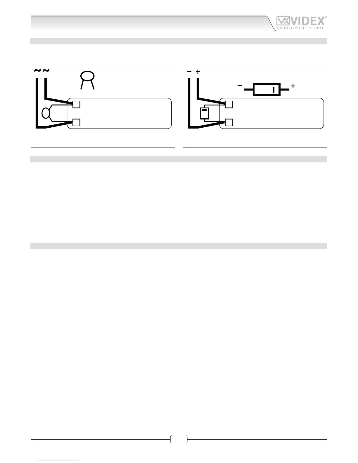
LOCK RELEASE BACK EMF PROTECTION
A capacitor must be fit ed across the terminals on AC lock release (Fig. 5) or a diode must be fit ed across the terminals on a DC lock
release (Fig. 6) to suppress back EMF voltages. Connect the components to the lock releases as shown in the figu es.
0.1uF capacitor
12V AC
LOCK RELEASE
DIODE
1N4002
12V DC
LOCK RELEASE
Fig. 5
DIODE
1N4002
12V DC
LOCK RELEASE
Fig. 6
RESTORE THE FACTORY PRESET
This procedure restores the module IP address and the user name/password access to the factory preset.
Other settings are not aected by this procedure.
• Power down the module;
• Make a link between the “PTE” and “GND” terminals (if the “Push to Exit” button is connected keep it pressed);
• Power up the module and wait until the name plate holder switches on and the module emits a double beep;
• Remove the link or release the “Push to Exit” button.
The factory presets are restored to the following:
IP address: 192.168.1.3
Username: admin
Password: admin
TECHNICAL SPECIFICATION
• 2 Dry contacts relay C, NC, NO: 24Vac/dc – 3A max
• Power supply voltage: 12Vdc
• Power consumption: 500mA max
• Working temperature: -10° +50° C
Connection
IPVK - IPVKC Series IP videokit
IPVK-IPVKC - Installation handbook
Page 11
66550060-EN - V1.0 - 06/02/14
11
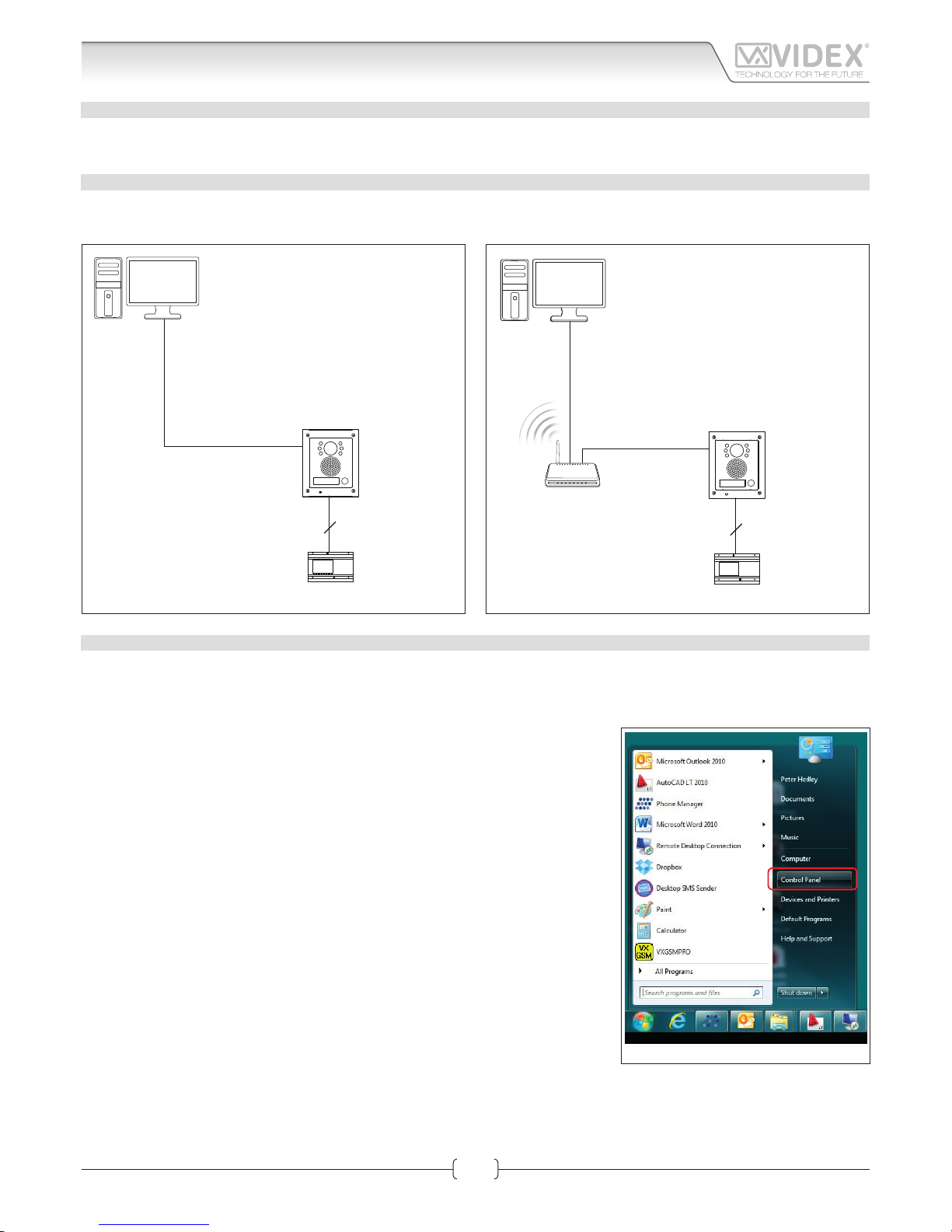
HARDWARE SETUP WITH CROSSOVER CABLE
Power up the Art.4503 and connect a crossover cable between the PC/Laptops network connection and the Art.4503 network
connection (TCP/IP) as shown in Fig. 1.
HARDWARE SET UP WITH SWITCH AND PATCH CABLE
Power up the Art.4503 and connect a patch cable between the Art.4503 network connection (TCP/IP) and the Switch and then
connect a patch cable between the PC/Laptops network connection and the Switch as shown in Fig. 2.
2
AMR2-12
12Vdc Power supply
Art.4503
IP door panel
Crossover cable
PC/Laptop
Fig. 1
2
Standard or
Wi-Fi Router
AMR2-12
12Vdc Power supply
Patch
Ethernet cable
Patch
Ethernet cable
Art.4503
IP door panel
PC/LaptopPC/Laptop
Fig. 2
HARDWARE SET UP NOTES
These first steps simply put your PC/laptop into the same IP range as the default Art.4503. There are many ways to reach the “Local
area connections” window depending on your windows set up. These steps present one of them (also see appendix for Windows
Vista/Windows 2000/XP).
First click on the start menus Windows icon in the bottom left of the screen and select
“Control Panel” from the list on the right hand-side as shown on Fig. 3.
Fig. 3
Art.4503 IP Video Speaker Unit Module
Hardware setup
IPVK - IPVKC Series IP videokit
IPVK-IPVKC - Installation handbook
Page 12
66550060-EN - V1.0 - 06/02/14
12
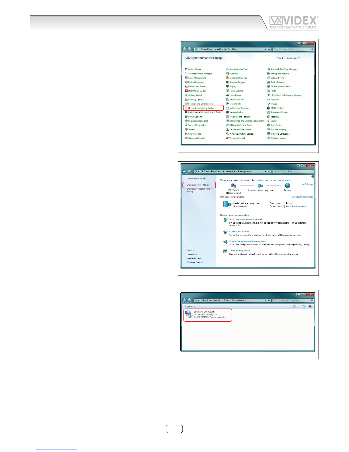
The “Control Panel” window shown on Fig. 4 will appear. Click on
“Network and Sharing Center” option.
The window shown on Fig. 5 will appear. Select “Change adap-
tor settings” option on the left hand-side.
The window shown on Fig. 6 will appear. Double click on the
“Local Area Connection” icon.
Fig. 4
Fig. 5
Fig. 6
Art.4503 IP Video Speaker Unit Module
Hardware setup
IPVK - IPVKC Series IP videokit
IPVK-IPVKC - Installation handbook
Page 13
66550060-EN - V1.0 - 06/02/14
13
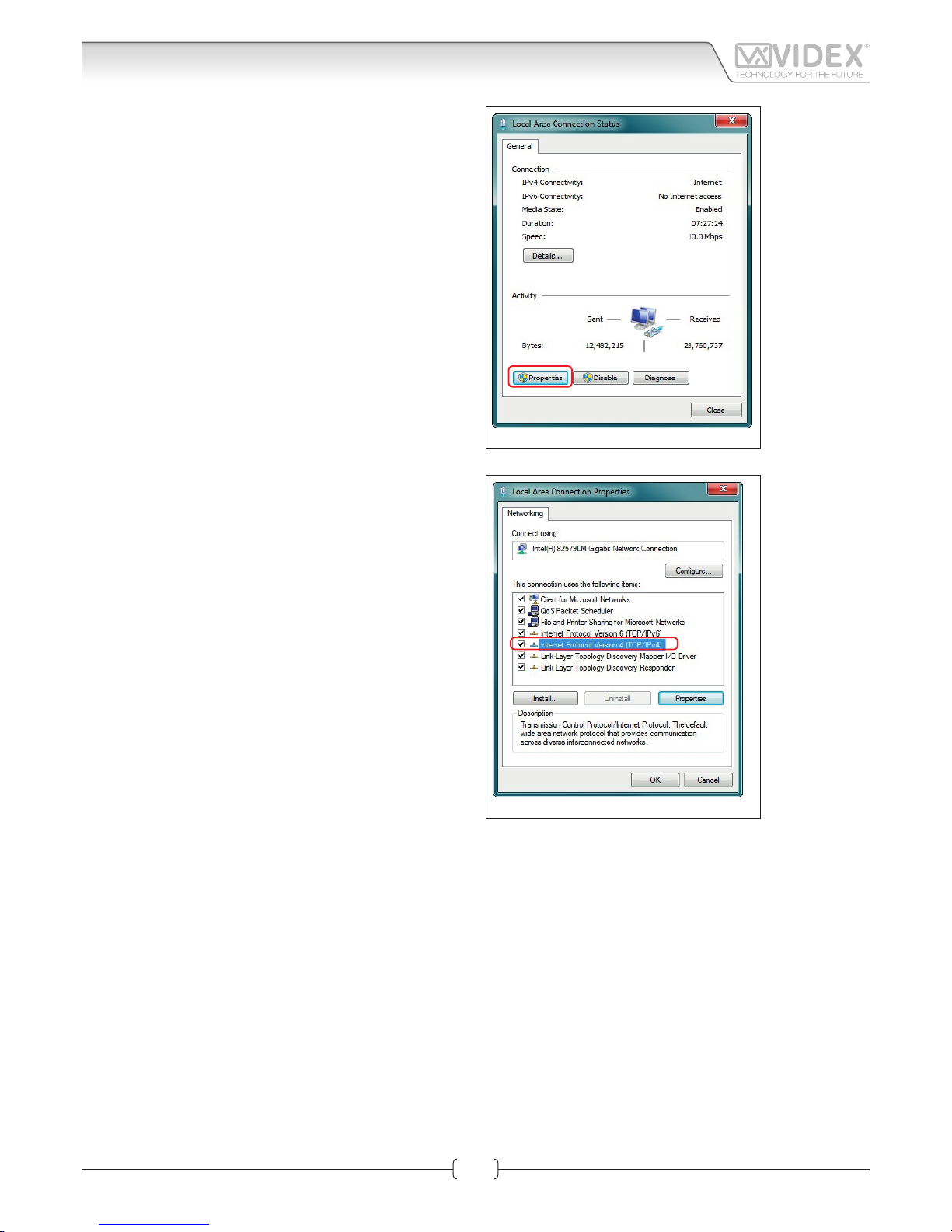
The “Local Area Connection Status” window shown on Fig. 7 will
appear. Click on the “Properties” button.
The “Local Area Connection Properties” window shown on Fig.
8 will appear. Highlight “Internet Protocol Version 4 (TCP/IPv4)”
from the list then click on the “Properties” button.
Fig. 7
Fig. 8
Art.4503 IP Video Speaker Unit Module
Hardware setup
IPVK - IPVKC Series IP videokit
IPVK-IPVKC - Installation handbook
Page 14
66550060-EN - V1.0 - 06/02/14
14
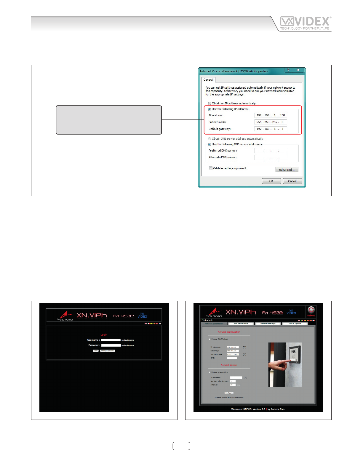
The “Internet Protocol Version 4 (TCP/IPv4) Properties” window shown on Fig. 9 will appear. Before changing settings in this window
first make a note of the current IP Address, Subnet mask and default gateway settings as you will need to restore them once the task
is complete. Select “Use the following IP address:” and complete the following details as highlighted.
Use the following IP address:
IP address: 192.168.1.150
Subnet mask: 255.255.255.0
Default gateway: 192.168.1.1
Fig. 9
IMPORTANT NOTE!
The default IP address of the Art.4503 is preset as “192.168.1.3”. When entering the information in the “Internet Protocol
Version 4 (TCP/IPv4) Properties” window (as shown above) the IP address that is entered must be within the same range
as the default IP address “192.168.1.3” in this example we are using “192.168.1.150”. The range of IP addresses can be between 1 to 255. Only the last set of digits of the IP address needs to be changed “192.168.1.n” where n = 1 to 255.
After completing the details (as shown above) click on “OK” and close all windows and exit “Control Panel”.
Your PC/laptop is now ready to change the Art.4503 default IP address to one suitable for your network.
Repeat these steps later to restore your PC/laptop back to its original settings.
Next click on the internet browser icon on your desktop and enter the following web address “http://192.168.1.3/” as shown then press enter.
NETWORK PARAMETERS CHANGES
Fig. 10 Fig. 11
The “LOGIN” web page shown on Fig. 10 should appear. Enter the default Username (in lower case) and Password then click on the
“Login” button.
Art.4503 IP Video Speaker Unit Module
Hardware setup
IPVK - IPVKC Series IP videokit
IPVK-IPVKC - Installation handbook
Page 15

66550060-EN - V1.0 - 06/02/14
15
The “Art.4503 Network Parameters” web page should appear as shown in Fig. 11.
The IP Address, SubnetMask and Gateway IP can now be changed. This information can be obtained from the network administrator.
Once all details have been updated on the “Art.4503 Network Parameters” web page press the “Configu e” button followed by “Apply configu ation”.
IMPORTANT NOTE!
Once you change the IP address you may not be able to connect using the PC/Laptop without repeating the previous steps
to make the PC/Laptop part of the same subnet as the device.
APPENDIX
WINDOWS VISTA
1. Open the start menu from the Windows icon in the bottom left of the screen and select “control panel” from the list on the right
hand-side.
2. Select the option “View network status and tasks”.
3. Select “Manage network connections”.
4. Double click on “Local Area Connection”.
5. Select the button “Properties” at the bottom of the window.
6. Select “Internet Protocol Version 4 (TCP/IPv4)” from the list, then select “Properties”.
7. Before changing any settings in this window first make a note of the current IP Address, Subnet mask and default gateway settings as you will need to restore them once the task is complete.
8. Complete the information as described on page 6.
9. After completing the details click on “OK” and close all windows and exit “control panel”.
10. Your PC/Laptop is now ready to change the Art.4503 default IP address to one suitable for your network.
11. Follow the steps as described on section “Network parameters changes” on page 14 to change the IP address of the Art.4503.
WINDOWS 2000/XP
1. Open the start menu from the Windows icon in the bottom left of the screen and select “control panel”.
2. In the “control panel” window double-click on the “Network and Dial-Up” connections icon.
3. Click on “Local Area Connection” to bring up a “local area network status” window.
4. In the “components checked are used by this connection” area, highlight “Internet Protocol (TCP/IP)” and click on the “Properties”
button.
5. The Internet Protocol (TCP/IP) properties window will appear.
6. Before changing any settings in this window first make a no e of the current IP Address, Subnet
7. mask and default gateway settings as you will need to restore them once the task is complete.
8. Complete the information as described on page 6.
9. After completing the details click on “OK” and close all windows and exit “control panel”.
10. Your PC/Laptop is now ready to change the Art.4503 default IP address to one suitable for your network.
11. Follow the steps as described on section “Network parameters changes” on page 14 to change the IP address of the Art.4503.
Art.4503 IP Video Speaker Unit Module
Hardware setup
IPVK - IPVKC Series IP videokit
IPVK-IPVKC - Installation handbook
Page 16

V1.0 - 06/02/14
16
Fig. 1 Login Fig. 2 Network parameters
LOGIN PAGE
It is recommended that this device is installed by an engineer with an understanding of Ethernet installations and TCP/IP protocols.
In the case of installations using existing networks it maybe necessary to request information from the network administrator.
More than one unit can be installed on a system. Each unit must have a unique IP address which is not currently in use on that
network.
The default network parameters are:
• Static IP Address: 192.168.1.3
• Subnet mask: 255.255.255.0
• User Name: admin
• Password: admin
If the default IP address on the device is free and in range with your network then, from a PC, tablet or smartphone connected to
the same network, open a browser and enter the URL “http://192.168.1.3”.
Alternatively if the default IP address is not compatible with your network it will be necessary to change this as shown in the
“Art.4503 Hardware setup” section on page 11.
The internal webserver will show the login page of Fig. 1.
Enter the user name and password then start to setup the IP module through the dierent tabs.
In case of problems or mistakes, the module can be restored to the factory preset following the procedure described in the section
“Restore the factory preset” on page 10.
NETWORK PARAMETERS
This tab allows the editing of all network parameters Fig. 2.
NETWORK CONFIGURATION
“Enable DHCP Client” allows the unit to obtain a dynamic IP address from the network. It is better to leave it disabled and use a fi ed
IP address.
Edit the fields of the subsection “Network configu ation” (Refer to the Network Settings paragraph on page”Network settings” on page
19 of this manual) according to the network requirements then press the “Configu e” button followed by “Apply configu ation”.
A short countdown signals that the device is updating the changes.
NETWORK CONTROL
“Enable Check Alive” enables the device to constantly check the ethernet connectivity.
When this option is set, the module will repeatedly check connection with the IP address entered and if connection is lost will force
a reboot of the unit. If you enable this setting you must set the IP address to ping, the number of connection attempts and the time
interval between the attempts. Enable this function when network connection problems could exist.
After changing this setting, press the “Configu e” button followed by “Apply configu ation”.
A short countdown signals that the device is updating the changes.
IPVK - IPVKC Series IP videokit
Art.4503 IP Video Speaker Unit Module
Web Server
Page 17

V1.0 - 06/02/14
17
Web Server
Fig. 3 SIP parameters & Call Buttons Fig. 4 General Settings
SIP PARAMETERS & CALL BUTTONS
In this section it is possible to enable SIP server communication and address the call buttons to call IP addresses or SIP ID’s of other
devices such as videophones, tables, smartphones or PC’s. Fig. 3
The use of the module in combination with a SIP server is an additional feature, if you are not using the IP speaker unit module with
a SIP server you don’t need to set the relevant fields but it is always necessary to set the IP addresses to be called when a specific
button is pressed.
For the correct setup of the “SIP SERVER CONNECTION” field , it is necessary to know the specific parameters of the SIP server to
which you are connecting the device.
Note: You need to press the edit button if you are changing previously stored settings.
If you are using a simplified SIP egistration ( “setup advanced logging” unchecked) the following parameters are requested:
• Username: it is the username used during the SIP account/extension generation on the SIP server.
• Password: it is the password for the username above used during the SIP account/extension generation on the SIP server.
• Server/Outbound proxy: is the server machine with name of DNS:port or IP:port
• Realm server: is the SIP protocol used
If you check “setup advanced logging” the following additional parameters are required:
• Extension: it is the numeric extension code generated on the SIP server for the username above.
• Domain: it is the domain of the service where you will try to register with. It can be an IP address or a fully qualified domain
After completing the SIP server connection fields emember to check the “Enable registration to server”.
Press the “Configu e” button followed by “Apply configu ation”. A short countdown signals that the device is updating the changes.
If the setup is correct, after a while, the “Registration Status” indicator should switch from RED to GREEN.
The dierent colours of the “Registration Status” indicator have the following meanings:
RED: registration to SIP server not enabled;
GREY: registration to SIP server enabled but the status is still not recognized;
ORANGE: registration to SIP server enabled but the server has still not confi med the registration;
GREEN: registration to SIP server enabled and the server has confi med the registration.
CALL BUTTONS
This subsection addresses the call buttons (2 integral to the module and up to 64 using the special interface module Art.4513 combined with standard expansion modules Art.4842..45).
• From the dropdown list, select the button for which you want to set the destination addresses.
• For the currently selected button, under the dropdown list, 10 fields will appear for IP addresses and 10 fields for SIP addresses.
• If you are using a connection to a SIP server, fill in the SIP Extension fields otherwise fill in the IP Address fields (from 1 to 10, each
button can call up to 10 devices).
• After completing all the necessary fields for the currently selected button, press “Configu e” followed by “Apply configu ation”. A
short countdown signals that the device is updating the changes.
• Repeats the steps above for each button on your device.
When a button is pressed it will call all the addresses for that call button simultaneously.
IPVK - IPVKC Series IP videokit
Art.4503 IP Video Speaker Unit Module
IPVK-IPVKC - Installation handbook
Page 18

V1.0 - 06/02/14
18
GENERAL SETTINGS
General settings can be changed from this tab Fig. 4.
LOCK CONFIGURATION
The unit includes two integral relays:
• Name: it is a descriptive name that can be used to identify the function of that relay (i.e. front door, rear door, gate etc.)
• Open code: it is a numeric code (1..9999) to activate the relay . If you are using the android client or the MS-Windows client, you
must store this code in the client to be able to enable the relay. Using a third party VOIP device that transmits DTMF tones in compliance with RFC2833 standard you can enable the relay by entering #XXX* where XXX is the numeric code stored for the relay.
• Open duration: It is the time in seconds (01..99) that the relay remains active when enabled.
CALL CONFIGURATION
Call setup parameters:
• Close all calls after the rejection: if checked, when one of the devices called rejects the call, the call stops for all the devices called
(Factory preset disabled).
• Fast recall (0..2): This parameter sets the modules behaviour when a new call button is pressed when a call or a conversation is
in progress (Factory preset 1).
0. Pressing a call button when a call has already begun will have no eect until that call ends.
1. If a call has begun but has not been answered, pressing a button will end that call and begin a new call. Useful if an incorrect
button is pressed.
2. Pressing a button during a call or conversation will end that call and begin a new call.
• Ring duration (10..60s): The maximum ring time before the call will clear down if not answered. (Factory preset 30).
• Call duration (60..240s): The maximum conversation time before the call will automatically clear down. (Factory preset 120).
• Fps: it is the video frame rate and should be set according to the available band width (Factory preset 8).
VIDEO CONFIGURATION
If you check the “disable video” option the module will make only audio calls.
AUDIO CONFIGURATION
This subsection adjust the loudspeaker and microphone volume levels
• Microphone volume (1..30): 1- lowest volume, 30 maximum volume (Factory preset 3)
• Speaker volume (1..30): 1- lowest volume, 30 maximum volume (Factory preset 2)
AUDIO CODEC ENABLED
Check all the audio codecs that you need to enable.
SERIAL PORT
Check “Enable expansion module (Art.4513)” if you are using the Art.4513 button interface module.
After making changes, press the “Configu e” button followed by “Apply configu ation”. A short countdown signals that the device is
updating the changes.
INFO & UPDATE
INFORMATIONS
This tab provides information and specific tions for the device:
• Device Name
• Firmware Version
• Supported audio codecs & band width
• Supported video codecs & band width
UPLOAD FIRMWARE
Under this section you can update the modules fi mware: first
select the file then press the upload button and follow the on
screen instructions.
Fig. 5 Info & Update
Art.4503 IP Video Speaker Unit Module
Web Server
IPVK - IPVKC Series IP videokit
IPVK-IPVKC - Installation handbook
Page 19

V1.0 - 06/02/14
19
CHANGE LOGIN DATA
If necessary you can change the access credentials (username
& password).
To change the access credentials, from the login page (Fig. 6)
first enter the current user name and password then click on the
“Change login data” button.
On the “Changing user data” page complete the fields
• New username: Enter the new user name
• New password: Enter the new password
• Confi m new password: enter the new password again.
After completing, click on the “Change login data” and wait to
be redirected to the login page. The new access credentials
must be used to enter.
NETWORK SETTINGS
Network settings (IP Address, Gateway, Subnet Mask and DNS) must be set according to the local area network (LAN).
This information will normally be available from the network administrator but may also be retrievable using a PC, smart phone or
tablet already connected to the network:-
This example uses Microsoft Windows 7 (Other versions of Windows may dier slightly):
• Open the “Control Panel” then double click on the “Network
and Sharing Center” icon;
• Click on “Local Area Connection” then click on the “Details”
Button
• The new window will show the network details, make a note
of the “IPv4 Address”, “IPv4 Subnet Mask”, “IPv4 DNS Server”
and “IPv4 Gateway”.
Fig. 6 Change login data
Fig. 7
Fig. 8
Art.4503 IP Video Speaker Unit Module
Web Server
IPVK - IPVKC Series IP videokit
IPVK-IPVKC - Installation handbook
Page 20

V1.0 - 06/02/14
20
• These details can now be used to setup your Videx devices.
Ensure you use a free IP address for each device (This should
be obtained from the network administrator or for a simple
home network it should be selected from outside the pool
of DHCP addresses (Use the ping command from the command prompt to check if the IP address is currently in use. i.e.
To test IP address 192.168.2.50, from the command prompt
type ‘ping 192.168.2.50’ and press return. If you receive a
timeout then the IP address is likely to be available. If you receive replies then the IP address is in use and another should
be used). Finally, use the details obtained above to complete
the “Subnet Mask”, “Gateway” and “DNS Server” field .
The “Gateway” and “DNS Server” settings are particularly important for internet services. For example, the use of domain
names, SIP settings and the weather application. For a simple
system such as a home setup with a single router this information can be obtained from the web server page on the router.
(You will need the IP address for this web page and it may also
be password protected). On larger networks you should always
obtain this information from the network administrator.
Fig. 10 Fig. 11
Fig. 9
Art.4503 IP Video Speaker Unit Module
Web Server
IPVK - IPVKC Series IP videokit
IPVK-IPVKC - Installation handbook
Page 21

66550060-EN - V1.0 - 06/02/14
21
4000 Series surface and flush mou ting door station installation
H
G
H
Y
G
C
F
E
D
B
A
C
L
H
L
P O
N
M
H
M
M
C
Q
P
C
D
W
N
N
C
H
g. 1
g. 8
g. 4 g. 5 g. 6 g. 7
g. 3
g. 10
g. 11
g. 15
g. 12
g. 16
g. 13
g. 17
g. 14
g. 18
g. 2
g. 9
EXAMPLE: INSTALLING A FOUR MODULE OUTDOOR STATION
IPVK - IPVKC Series IP videokit
IPVK-IPVKC - Installation handbook
Page 22

66550060-EN - V1.0 - 06/02/14
22
4000 Series surface and flush mou ting door station installation
INSTALLING A SURFACE MOUNT DOOR STATION
1. Place the surface box against the wall (165-170cm between the top of the box and the floor le el as shown in Fig.1) and mark the
fixing holes or the wall plugs and the hole for the cables E (g.2). Observe the orientation of the box with the hinge on the left;
In order to prevent water ingress we highly recommend using a silicon sealant between the wall and the back box C
(Fig.3) and around all holes D (Fig.3);
2. As shown on Fig.2, drill the fixing holes A, insert the wall plugs B and feed the cables E through the surface box opening D, fi
surface box C to the wall using the screws F;
3. Apply the Y silicon sealant on top of each module as shown in Fig.4;
4. Before installation of the module support frame, hook the modules G to the support frame H as shown in Fig.5 then, as shown
in Fig. 6, fit the wo anti-tampering locks W for each module (do the same for the second module support frame);
5. When you have more than one support frame, hook the support frame to the surface box starting from the left. For convenience we
will described how to attach the left frame but the same must be carried out for the right frame. As shown in Fig. 7, hook the module
support frame H (complete with modules) to the surface box C moving the frame as suggested from pointers. Ensure that the pivots
L (Fig. 7) go inside the relevant housing M as shown in Fig. 8;
6. As shown on Fig. 9, pull back the module support frame H while moving it slightly to the left as suggested by the pointers;
7. As shown in Fig. 10, open the module support frame H as suggested by the pointer, hook the hinge locks N to the hinges M,
make the required connections using the screwdriver provided P (fl t blade end) and make the required adjustment by adjusting the settings (through openings O) and adjust trimmers;
8. Repeat the same operations described above for the second module support frame (or for the third if available);
9. When the system has been tested and is working correctly, move back the module support frames carefully, fix them to the surface
box using the screwdriver provided P (torx end) and the pin machine torx screws Q (Fig. 11). Note: do not over tighten the screws
more than is necessary.
INSTALLING A FLUSH MOUNTING DOOR STATION
When flush mounting and the number of modules is greater than 3, the required back boxes need to be linked together (before
embedding them in the wall) as shown on Fig. 14, 15 and 16:
• Arrange the back boxes and remove knockouts to allow cables to be fed from one back box to the other;
• Hook the spacers to first back b x then hook the second back box to obtain the result shown on Fig. 16;
1. Protect the module support frame fixing holes from dust then embed the back box into the wall (165-170cm between the top
of the box and the floor level as shown on the Fig. 1) feeding the cables E (Fig. 2) through a previously opened hole in the box.
Observe the direction of the box ensuring the hinge is on the left and take care that the box profile is in line with the finishe
wall profile
In order to prevent water ingress we highly recommend using a silicon sealant between the wall and the back box H
(Fig.12);
2. Continue from step 4 of surface mounting instructions , but at step 7 hook the hinge locks N as shown on Fig. 13.
Note: if additional holes are made in the surface box, oxidation problems may appear unless the unprotected metal is
coated with a protective paint.
NOTES
• The screwdriver’s blade has two sides, one fl t and one torx, to select one of them unplug the blade from the screwdriver body
and plug it into the required side.
• The example shows the use of only one back box bottom hole for wires, this is done to keep file drawings clear. Naturally the
installer can use the left hole or the right or both if required.
HOW TO REMOVE THE CARD NAME HOLDER
• To avoid damage to the module front plate, tape the side that will be in contact with the screwdriver blade;
• lnsert the screwdriver (fl t side) into the card-holder hole as shown in Fig. 17;
• Move the screwdriver to the left as shown in Fig. 18 to extract the card name holder;
• Edit the card name then replace it inside the holder and refit: insert the holder inside its housing from the left or right side then
push the other side until it clips into place.
IPVK - IPVKC Series IP videokit
IPVK-IPVKC - Installation handbook
Page 23

66550060-EN - V1.0 - 05/02/14
23
IPVK - IPVKC Series IP videokit
IPVK-IPVKC - Installation handbook
112 42
155
182
29
LAN
+12Vdc
GND
Made in Italy
KRV98
KRV96
/W (white)
/B (black)
H
L
CAN BUS
Fig. 1 KRV96
120
190
839
189
119
LAN
+12Vdc
GND
Made in Italy
KRV98
KRV96
/W (white)
/B (black)
H
L
CAN BUS
Fig. 2 KRV98
DESCRIPTION
• Kristallo design with touch sensitive buttons;
• 3.5” LCD TFT High Definition Displ y
• Available in a flush mounting (handsfree) version or surface mount version with handset (for handsfree or conventional). A desk
mount kit is available for the surface with handset version,
• 10/100 Mbit Ethernet interface;
• PoE or 12Vdc power supply;
• Compatible with the SIP protocol (it can be connected with VOIP switchboard systems);
• Built in web server to set operation parameters;
• Firmware can be updated through a web server;
• Self search function and self setting of Videx IP devices connected on the same network;
• Integrated picture memory facility with automatic capture;
• Privacy function with programmable activation time from 30 min to 24 h or unlimited;
• History of events;
Art.KRV98-KRV96 3.5" IP Videointercom
Connection
Page 24

66550060-EN - V1.0 - 05/02/14
24
IPVK - IPVKC Series IP videokit
IPVK-IPVKC - Installation handbook
• Intercommunication with other devices of the system (outdoor stations, videophones, tablet or PC with client installed) user can
be selected through a complete contacts list or through “favorites” (communication with outdoor stations is audio/video and it’s
possible to activate the relays);
• It is possible to activate the relays of the outdoor stations through a menu option;
• “Weather forecast” function through google weather service (an internet connection to the network is required);
• Melody and desktop can be customized by loading audio files and pi tures.
BUTTONS OPERATION IN STANDBY MODE
With the video intercom in stand-by and the monitor switched o, press any button to switch on.
RAPID CALL BUTTON
By pressing this button you access directly into the “rapid call” submenu. If the list includes one contact only
the call starts directly.
LOCKS
By pressing this button you access directly into the “locks” menu (See LOCKS paragraph in Graphic Interface section).
PRIVACY FUNCTION
By pressing this button you enable the privacy service (the relevant LED switches on) and the videointercom
receives incoming calls but doesn’t switch on the audio or the video connection.
The service is disabled by the privacy time expiring or by pressing the same button again.
MENU NAVIGATION BUTTON
If the videointercom is in stand-by but the monitor is switched o, first p ess any button to switch on the display.
or
With the videointercom in stand by and switched on it selects the previous menu icon
or
With the videointercom in stand by and switched on it selects the next menu icon
With the videointercom in stand by and switched on it enters in the currently selected menu icon
TERMINALS
L
Not used
H
LAN 10/100Mb Ethernet Interface RJ45 plug
+12Vdc 12Vdc - 500mA Power Supply Input
0Vdc Ground
TECHNICAL SPECIFICATION
• Power supply voltage: 12Vdc
• Power consumption: 500mA max
• Working temperature: -10° +50° C
IP VIDEOINTERCOM RESTORE TO FACTORY PRESET
To restore the settings to the factory preset proceed as follows:
1. Power down the video intercom (disconnect the power supply connector or in case of POE switch/router disconnect the
Ethernet cable);
2. On the rear side of the video intercom, on the 28 way connector, put in short the two terminals as shown in Fig. 3;
3. Power on the video intercom and wait for the boot;
4. Remove the link when the video intercom emits an acoustic signal;
5. Once the boot is complete the video intercom is ready to work;
The video intercom settings are restored to the following:
Network Parameters
IP Address: 192.168.1.4
Net Mask: 255.255.255.0
Gateway: 192.168.1.1
DNS Server: 8.8.8.8
Login Credentials
Username: admin
Password: admin
Advanced Setup Password
Password: 0000
14
13
12
11
10
9
8
7
6
5
4
3
2
1
28
27
26
25
24
23
22
21
20
19
18
17
16
15
RESET
BUTTON
Fig. 3
Art.KRV98-KRV96 3.5" IP Videointercom
Connection
Page 25

66550060-EN - V1.0 - 05/02/14
25
IPVK - IPVKC Series IP videokit
IPVK-IPVKC - Installation handbook
IP VIDEO INTERCOM MANUAL RESET
In case the system locks (touch sensitive buttons not recognized) you can reset manually the video intercom:
1. On the rear side of the video intercom, under the 28 way connector there is a small button see Fig. 3;
2. Using a thickness tool, press shortly the button and wait for the video intercom reboot;
3. Once the boot is complete the video intercom is ready to work;
This procedure reboots only the video intercom without aect any setting.
POWER SUPPLY & CONNECTION
In case of POE (Power Over Ethernet) Switch/Router, follow the connection shown in Fig. 4 otherwise, in case of standard Switch/
Router, follow the connection shown in figu e Fig. 5.
LAN
+12Vdc
GND
Made in Italy
KRV98
KRV96
/W (white)
/B (black)
H
L
CAN BUS
LAN
+12Vdc
GND
Made in Italy
KRV98
KRV96
/W (white)
/B (black)
H
L
CAN BUS
Connect to a POE (Power Over
Ethernet) Switch or Router
Connect to a POE (Power Over
Ethernet) Switch or Router
Fig. 4
LAN
+12Vdc
GND
Made in Italy
KRV98
KRV96
/W (white)
/B (black)
H
L
CAN BUS
LAN
+12Vdc
GND
Made in Italy
KRV98
KRV96
/W (white)
/B (black)
H
L
CAN BUS
230V
12Vdc
Art.AMR2-12
or
12Vdc 2A
PSU
230V
12Vdc
Art.AMR2-12
or
12Vdc 2A
PSU
Connect to a Switch,
Router or directly** to the
ethernet interface of the
Art.4503
Connect to door panel's
power supply unit*
Connect to a Switch,
Router or directly** to the
ethernet interface of the
Art.4503
Connect to door panel's
power supply unit*
To Art.4503
To Art.4503
Fig. 5
* When the devices are connected directly certain features which require the internet will not be available.
** If the videointercom is not connected to a POE switch or router, it is necessary to connect an external PSU (terminals “+12Vdc” & “GND”). If the videointercom is provided in a video kit, you can use
the PSU included in the video kit. For distances between the videointercom and the PSU up to 25 metres use 2 cables 1.0mm2 (AWG17).
Connection
Art.KRV98-KRV96 3.5" IP Videointercom
Page 26

66550060-EN - V1.0 - 04/02/14
26
HARDWARE SETUP WITH CROSSOVER CABLE
Power up the Art.KRV98/96 and connect a crossover cable between the PC/Laptops network connection and the Art.KRV98/96
network connection (TCP/IP) as shown in Fig. 1.
HARDWARE SET UP WITH SWITCH AND PATCH CABLE
Power up the Art.KRV98/96 and connect a patch cable between the Art.KRV98/96 network connection (TCP/IP) and the Switch and
then connect a patch Ethernet cable between the PC/Laptops network connection and the Switch as shown in Fig. 2.
2
AMR2-12
12Vdc Power supply
Crossover cable
PC/Laptop
Art.KRV96/98
IP videophone
Fig. 1
2
Standard or
Wi-Fi Router
AMR2-12
12Vdc Power supply
Patch
Ethernet cable
Patch
Ethernet cable
PC/Laptop
Art.KRV96/98
IP videophone
Fig. 2
HARDWARE SET UP NOTES
These first steps simply put your PC/laptop into the same IP range as the default Art.KRV98/96. There are many ways to reach the
“Local area connections” window depending on your windows set up. These steps present one of them (also see appendix for Windows Vista/Windows 2000/XP).
First click on the start menus Windows icon in the bottom left of the screen and select
“Control Panel” from the list on the right hand-side as shown in Fig. 3.
Fig. 3
Art.KRV98-KRV96 Hardware setup
IPVK - IPVKC Series IP videokit
IPVK-IPVKC - Installation handbook
Page 27

66550060-EN - V1.0 - 04/02/14
27
The “Control Panel” window shown in Fig. 4 will appear. Click on
“Network and Sharing Center” option.
The window shown in Fig. 5 will appear. Select “Change adaptor
settings” option on the left hand-side.
The window shown in Fig. 6 will appear. Double click on the “Lo-
cal Area Connection” icon.
Fig. 4
Fig. 5
Fig. 6
Art.KRV98-KRV96 Hardware setup
IPVK - IPVKC Series IP videokit
IPVK-IPVKC - Installation handbook
Page 28

66550060-EN - V1.0 - 04/02/14
28
The “Local Area Connection Status” window shown in Fig. 7 will
appear. Click on the “Properties” button.
The “Local Area Connection Properties” window shown in Fig.
8 will appear. Highlight “Internet Protocol Version 4 (TCP/IPv4)”
from the list then click on the “Properties” button.
Fig. 7
Fig. 8
Art.KRV98-KRV96 Hardware setup
IPVK - IPVKC Series IP videokit
IPVK-IPVKC - Installation handbook
Page 29

66550060-EN - V1.0 - 04/02/14
29
The “Internet Protocol Version 4 (TCP/IPv4) Properties” window shown in Fig. 9 will appear. Before changing settings in this window
first make a note of the current IP Address, Subnet mask and default gateway settings as you will need to restore them once the task
is complete. Select “Use the following IP address:” and complete the following details as highlighted.
Use the following IP address:
IP address: 192.168.1.150
Subnet mask: 255.255.255.0
Default gateway: 192.168.1.1
Fig. 9
IMPORTANT NOTE!
The default IP address of the Art.KRV98/96 is preset as “192.168.1.4”. When entering the information in the “Internet Protocol Version 4 (TCP/IPv4) Properties” window (as shown above) the IP address that is entered must be within the same range
as the default IP address “192.168.1.4” in this example we are using “192.168.1.150”. The range of IP addresses can be between 1 to 255. Only the last set of digits of the IP address needs to be changed “192.168.1.n” where n = 1 to 255.
After completing the details (as shown above) click on “OK” and close all windows and exit “Control Panel”.
Your PC/laptop is now ready to change the Art.KRV98/96 default IP address to one suitable for your network.
Repeat these steps later to restore your PC/laptop back to its original settings.
Next click on the internet browser icon on your desktop and enter the following web address “http://192.168.1.4/” as shown then press enter.
NETWORK PARAMETERS CHANGES
Fig. 10 Fig. 11
The “LOGIN” web page shown on Fig. 10 should appear. Enter the default Username (in lower case) and Password then click on the
“Login” button.
Art.KRV98-KRV96 Hardware setup
IPVK - IPVKC Series IP videokit
IPVK-IPVKC - Installation handbook
Page 30

66550060-EN - V1.0 - 04/02/14
30
The “Art.KRV98/96 Network Parameters” web page should appear as shown in Fig. 11.
The IP Address, SubnetMask and Gateway IP can now be changed. This information can be obtained from the network administrator.
Once all details have been updated on the “Art.KRV98/96 Network Parameters” web page press the “Configu e” button followed by
“Apply configu ation”.
IMPORTANT NOTE!
Once you change the IP address you may not be able to connect using the PC/Laptop without repeating the previous steps
to make the PC/Laptop part of the same subnet as the device.
APPENDIX
WINDOWS VISTA
12. Open the start menu from the Windows icon in the bottom left of the screen and select “control panel” from the list on the right
hand-side.
13. Select the option “View network status and tasks”.
14. Select “Manage network connections”.
15. Double click on “Local Area Connection”.
16. Select the button “Properties” at the bottom of the window.
17. Select “Internet Protocol Version 4 (TCP/IPv4)” from the list, then select “Properties”.
18. Before changing any settings in this window first make a note of the current IP Address, Subnet mask and default gateway settings as you will need to restore them once the task is complete.
19. Complete the information as described on page 6.
20. After completing the details click on “OK” and close all windows and exit “control panel”.
21. Your PC/Laptop is now ready to change the Art.KRV98/96 default IP address to one suitable for your network.
22. Follow the steps as described on section “Network parameters changes” on page 29 to change the IP address of the Art.
KRV98/96.
WINDOWS 2000/XP
12. Open the start menu from the Windows icon in the bottom left of the screen and select “control panel”.
13. In the “control panel” window double-click on the “Network and Dial-Up” connections icon.
14. Click on “Local Area Connection” to bring up a “local area network status” window.
15. In the “components checked are used by this connection” area, highlight “Internet Protocol (TCP/IP)” and click on the “Properties”
button.
16. The Internet Protocol (TCP/IP) properties window will appear.
17. Before changing any settings in this window first make a no e of the current IP Address, Subnet
18. mask and default gateway settings as you will need to restore them once the task is complete.
19. Complete the information as described on page 6.
20. After completing the details click on “OK” and close all windows and exit “control panel”.
21. Your PC/Laptop is now ready to change the Art.KRV98/96 default IP address to one suitable for your network.
22. Follow the steps as described on section “Network parameters changes” on page 29 to change the IP address of the Art.
KRV98/96.
Art.KRV98-KRV96 Hardware setup
IPVK - IPVKC Series IP videokit
IPVK-IPVKC - Installation handbook
Page 31

66550060-EN - V1.0 - 06/02/14
31
IPVK - IPVKC Series IP videokit
IPVK-IPVKC - Installation handbook
LOGIN
It is recommended that this device is installed by an engineer
with an understanding of Ethernet installations and TCP/IP
protocols. In the case of installations using existing networks it
maybe necessary to request information from the network administrator.
More than one unit can be installed on a system. Each unit must
have a unique IP address which is not currently in use on that
network.
The default network parameters are:
• Static IP Address: 192.168.1.4*
• Subnet mask: 255.255.255.0
• User Name: admin
• Password: admin
* If the videointercom is provided in a two way videokit the default ip address for the “videointercom 1” is “192.168.1.4” while for
the “videointercom 2” is “192.168.1.5”.
If the default IP address on the device is free and in range with your network then, from a PC, tablet or smartphone connected to
the same network, open a browser and enter the URL “http://192.168.1.4”.
Alternatively if the default IP address is not compatible with your network it will be necessary to change this firs . A guide to this
can be found under the “Art.KRV98-KRV96 Hardware setup” section on page 26. The internal webserver will show the login page
of Fig. 1
Enter the user name and password then start to setup the IP Videointercom through the dierent tabs.
In case of problems or mistakes, the videointercom can be restored to the factory preset following the procedure described in the
“IP videointercom restore to factory preset” section on page 24
NETWORK PARAMETERS
This tab allows the editing of all network parameters Fig. 2.
NETWORK CONFIGURATION
“Enable DHCP Client” allows the unit to obtain a dynamic IP address from the network. It is better to leave it disabled and use
a fi ed IP address.
Edit the fields of the subsection “Network configu ation” (Refer
“Network configu ation” sections on page 19 and 35 of this
manual) according to the network requirements then press the
“Configu e” button followed by “Apply configu ation”.
A short countdown signals that the device is updating the
changes.
NETWORK CONTROL
“Enable Check Alive” enables the device to constantly check the
ethernet connectivity.
When this option is set, the module will repeatedly check connection with the IP address entered and if connection is lost will
force a reboot of the unit. If you enable this setting you must set
the IP address to ping, the number of connection attempts and
the time interval between the attempts. Enable this function
when network connection problems could exist.
After changing this setting, press then the “Configu e” button followed by “Apply configu ation”.
A short countdown signals that the device is updating the changes.
Fig. 1 Login
Fig. 2 Network Parameters
Art.KRV98-KRV96 3.5" IP Videointercom
Web Server
Page 32

66550060-EN - V1.0 - 06/02/14
32
IPVK - IPVKC Series IP videokit
IPVK-IPVKC - Installation handbook
SIP PARAMETERS
In this section it is possible the enable SIP server communication (Fig. 3).
The use of the module in combination with a SIP server is an additional feature, if you are not using the IP speaker unit module
with a SIP server you don’t need to set the relevant field .
For the correct setup of the “SIP SERVER CONNECTION” field , it
is necessary to know the specific parameters of the SIP server to
which you are connecting the device.
Note: You need to press the edit button if you are changing previously stored settings.
If you are using a simplified SIP registration ( “setup advanced
logging” unchecked) the following parameters are requested:
• Username: it is the username used during the SIP account/
extension generation on the SIP server.
• Password: it is the password for the username above used
during the SIP account/extension generation on the SIP
server.
• Server/Outbound proxy: is the server machine with name of
DNS:port or IP:port
• Realm server: is the SIP protocol used
If you check “setup advanced logging” the following additional
parameters are required:
• Extension: it is the numeric extension code generated on
the SIP server for the username above.
• Domain: it is the domain of the service where you will try
to register with. It can be an IP address or a fully qualified
domain.
After completing the SIP server connection fields remember to
check the “Enable registration to server”.
Press the “Configu e” button followed by “Apply configu ation”.
A short countdown signals that the device is updating the
changes.
If the setup is correct, after a while, the “Registration Status” indicator should switch from RED to GREEN.
SETTINGS
This tab has 3 subsections:
• "Weather" (Fig. 4) to set the weather services;
• "General settings" (Fig. 5) to set language and monitor backlight options;
• "Modify Password" (Fig. 6 to set the password required for
the advanced settings;
WEATHER
If an internet connection is available on the network, it is possible to enable the weather forecast service through Google
Weather. The videointercom will show the weather forecast for
the selected area.
• Check "Enable weather forecast" to enable the service;
• Complete "Enter a location" field entering the name of the
location. While entering the name, the system will suggest
the possible cities. This setup also aects the automatic date
& time correction.
Press the “Configu e” button followed by “Apply configu ation”.
A short countdown signals that the device is updating the
changes.
Fig. 3 SIP parameters
Red
Registration to SIP server not enabled
Gray
Registration to SIP server enabled but the
status is still not recognized
Orange
Registration to SIP server enabled but the
server has still not confi med the registration
Green
Registration to SIP server enabled and the
server has confi med the registration.
Fig. 4 Settings - Weather
Art.KRV98-KRV96 3.5" IP Videointercom
Web Server
Page 33

66550060-EN - V1.0 - 06/02/14
33
IPVK - IPVKC Series IP videokit
IPVK-IPVKC - Installation handbook
GENERAL SETTINGS
• Language: set the language to be used in the user graphic
interface of the videointercom, click on the field then select
the required language from the listbox.
• Backlight duration: it is the time in seconds before which
the display goes into energy saving mode. In energy saving
mode the display is switched o.
Press the “Configu e” button followed by “Apply configu ation”.
A short countdown signals that the device is updating the
changes.
MODIFY PASSWORD
The password that you can modify in this tab is the protection
password required to access the advanced settings from the
graphical interface of the videointercom. It is a numeric code
composed of 4 digits. The default password is 0000.
• Old Password: Enter the old password ;
• New Password: Enter the new password;
• Confi m new password: Repeat the new password.
Press the “Configu e” button followed by “Apply configu ation”.
A short countdown signals that the device is updating the
changes.
Fig. 5 General Settings
Fig. 6 Modify Password
Art.KRV98-KRV96 3.5" IP Videointercom
Web Server
Page 34

66550060-EN - V1.0 - 06/02/14
34
IPVK - IPVKC Series IP videokit
IPVK-IPVKC - Installation handbook
INFO & UPDATES
This tab (Fig. 7) provides information about the fi mware version, allows fi mware updates and to upload files to be used for
melody or as the background picture.
UPLOAD FIRMARE
Under this section you can update the videointercoms fi mware:
first select the file then press the upload button and follow the
on screen instructions.
UPLOAD FILE
Under this section you can upload a file: first sel t the file then
press the upload button and follow the on screen instructions.
The file size must be no more than 2Mb, if the file extension is
“JPG” or “PNG” the file can be used as background picture while
if the extension is “WAV” or “MP3” the filewill be used as melody.
From the video intercoms user interface it will be possible to
select these file .
LOG FILES
This tab is for technical support purposes. If necessary, it is possible to download the log file to send to the technical support in
case of malfunctioning.
CHANGE LOGIN DATA
If necessary you can change the access credentials (username
& password).
To change the access credentials, from the login page (Fig. 1)
first enter the current user name and password then click on the
button “Change login data” .
In the page “Changing user data” fill in the equired fields
• New username: Enter the new user name
• New password: Enter the new password
• Confi m new password: Enter again the password above
After completing, click on the “Change login data” and wait to
be redirected to the login page. The new access credentials
must be used to enter.
Fig. 7 Info & Updates
Fig. 8 Log file
Fig. 9 Change Login Data
Art.KRV98-KRV96 3.5" IP Videointercom
Web Server
Page 35

66550060-EN - V1.0 - 06/02/14
35
IPVK - IPVKC Series IP videokit
IPVK-IPVKC - Installation handbook
NETWORK SETTINGS
Network settings (IP Address, Gateway, Subnet Mask and DNS) must be set according to the local area network (LAN).
This information will normally be available from the network administrator but may also be retrievable using a PC, smart phone or
tablet already connected to the network:-
This example uses Microsoft Windows 7 (Other versions of Windows may dier slightly):
• Open the “Control Panel” then double click on the “Network
and Sharing Center” icon;
• Click on “Local Area Connection” then click on the “Details”
Button
• The new window will show the network details, make a note
of the “IPv4 Address”, “IPv4 Subnet Mask”, “IPv4 DNS Server”
and “IPv4 Gateway”.
Fig. 10
Fig. 11
Web Server
Art.KRV98-KRV96 3.5" IP Videointercom
Page 36

66550060-EN - V1.0 - 06/02/14
36
IPVK - IPVKC Series IP videokit
IPVK-IPVKC - Installation handbook
• These details can now be used to setup your Videx devices.
Ensure you use a free IP address for each device (This should
be obtained from the network administrator or for a simple
home network it should be selected from outside the pool
of DHCP addresses (Use the ping command from the command prompt to check if the IP address is currently in use. i.e.
To test IP address 192.168.2.50, from the command prompt
type ‘ping 192.168.2.50’ and press return. If you receive a
timeout then the IP address is likely to be available. If you receive replies then the IP address is in use and another should
be used). Finally, use the details obtained above to complete
the “Subnet Mask”, “Gateway” and “DNS Server” field .
The “Gateway” and “DNS Server” settings are particularly important for internet services. For example, the use of domain
names, SIP settings and the weather application. For a simple
system such as a home setup with a single router this information can be obtained from the web server page on the router.
(You will need the IP address for this web page and it may also
be password protected). On larger networks you should always
obtain this information from the network administrator.
Fig. 13 Fig. 14
Fig. 12
Art.KRV98-KRV96 3.5" IP Videointercom
Web Server
Page 37

66550060-EN - V1.0 - 04/02/14
37
IPVK - IPVKC Series IP videokit
IPVK-IPVKC - Installation handbook
MENU NAVIGATION BUTTONS
Fig. 1 shows the videointercom’s default screen, if the display is
switched o, press any button to switch it on.
By pressing the
or button you select the next menu
icon while by pressing the
or button you select the
previous menu icon.
By pressing the
button you enter the submenu of the cur-
rently selected icon.
By pressing the
button, you enter directly into the “rapid
call” submenu. If the list includes one contact only the call starts
directly.
By pressing the
button, you enter directly into the “locks”
submenu.
By pressing the
button, you enable the privacy service. It
remains enabled according to the settings made.
This icon on the top left of the screen indicates
a missed call.
SIP SERVER REGISTRATION STATUS ICON
The dierent colours have the following meanings:
RED: registration to SIP server not enabled;
GREY: registration to SIP server enabled but the status is still not recognized;
ORANGE: registration to SIP server enabled but the server has still not confi med the registration;
GREEN: registration to SIP server enabled and the server has confi med the registration.
DATE & TIME
If an internet connection is available, the date & time are automatically configu ed according to the location set in the “settings”->
“weather” section of the internal webserver.
MENU ICONS
Contact Rapid Call Locks Chronology App Settings
Select one of the menu icons above using the buttons and or and then press the button.
CONTACT
This submenu allows you to call the stored contacts.
The stored contacts can be Videx IP Speaker Units,
other Videx IP Videointercoms, PCs using XN.Client-
Sip software or smartphones/tablets using Xefi oSip
android client. A video call is only possible with the videx door
panel.
• The display shows the list of stored contacts (Fig.2);
• Highlight the contact to call using the
or but-
tons then press the
button.
• The call starts (see CALL & CONVERSATION section)
Press the
button to go back to the main menu.
10:30
Contact
Rapid Call
Locks
Settings
Apps
Tuesday, December 4, 2013
Fig. 1 - Standard videointercom screen
XN-Panel
IP:192.168.1.5
XN-ViPh2
IP:192.168.1.2
XN-ViPh3
IP:192.168.1.3
10:30
Back
Contact
Fig. 2 - Contacts
Art.KRV98-KRV96 3.5" IP Videointercom
Graphic Interface
Page 38

66550060-EN - V1.0 - 04/02/14
38
IPVK - IPVKC Series IP videokit
IPVK-IPVKC - Installation handbook
RAPID CALL
This submenu allows you to call your favourite con-
tacts (Videx IP Speaker Units, other Videx IP Videoint-
ercoms, PCs using XN.ClientSip software or smart-
phones/tablets using Xefi oSip android client):
• If there is only one contact in the favourites list, the call starts
immediately (Fig. 16) otherwise the display shows the contacts stored in the favourites list (Fig. 3);
• Highlight the contact to call using the
or but-
tons then press the
button.
• The call starts (see CALL & CONVERSATION section)
Press the
button to go back to the main menu.
LOCKS
This submenu allows you to activate the door panels
built-in relays. This screen shows the list of available
door panels (Fig. 4).
• First highlight he door panel using the
or buttons.
• Press the
button to enable relay 1 or the button
to enable relay 2 (If both relays are connected).
• The display signals the relay activation status
Relay 1
Relay 2
Press the
button to go back to the main menu.
CHRONOLOGY
This submenu shows the list of call events. The icon
on the left of the event specifies the e ent type:
Incoming Call, Outgoing Call and
missed call. If the event shows the icon
this means that there is a picture stored. The picture is captured
from the door panel camera to show the caller.
• Highlight the event using the
or buttons then
press the
button to recall (see CALL & CONVERSA-
TION section) the device or press the
button to view the
stored picture when available.
• To delete the complete chronology list press the
but-
ton. A confi mation of this request is required. Press the
button to confi m or the
button to cancel the deletion.
Press the
button to go back to the main menu.
XN-ViPh2
IP:192.168.1.2
XN-ViPh3
IP:192.168.1.3
10:30
Back
Rapid Code
Fig. 3 - Rapid Call
XN-ViPh2
IP:192.168.1.2
XN-ViPh3
IP:192.168.1.3
10:30
Back
Rapid Code
Fig. 4 - Locks
XN-Panel
IP:192.168.1.5
00:05
18:19:39
04-12-2013
XN-ViPh2
IP:192.168.1.2
01:35
19:16:46
04-12-2013
XN-ViPh3
IP:192.168.1.3
00:35
22:45:13
04-12-2013
10:30
Back
Chronology
DeletePhoto
Fig. 5 - Chronology
Art.KRV98-KRV96 3.5" IP Videointercom
Graphic Interface
Page 39

66550060-EN - V1.0 - 04/02/14
39
IPVK - IPVKC Series IP videokit
IPVK-IPVKC - Installation handbook
APPS
This section displays the icons for installed apps.
• Select the APP using the
or buttons then press
the
button twice.
FORECAST (requires internet connectivity)
If correctly configu ed under the videointercom web server section “general settings->weather”, this APP will show the weather
forecast for the next 3 days.
Press the
button to go back to the main menu.
SETTINGS
This submenu includes 5 subpages and allows the following settings:
• Audio 1/5
• Display 2/5
• Date & Time 3/5
• Network 4/5
• Search 5/5
Without any active selection, navigate among the subpages using the
or buttons.
Press the
button to go back to the main menu.
AUDIO SETTINGS
This subpage (Fig. 7) allows you to change the ringtone melody,
the ringtone volume and the microphone & loudspeaker
volumes.
• Highlight the parameter to change using the
or
buttons.
• Change the value of the selected parameter using the
or buttons.
• Press the
button to go back to the sub page navigation
(no parameters highlighted).
Press the
button to go back to the main menu or navigate
among the subpages by pressing the
or buttons.
1/1
10:30
Back
Apps
Forecast
Fig. 6 - Apps
1/5
10:30
Short_ring.mp3
200 40 60 80 100
200 40 60 80 100200 40 60 80 100
Back
Settings
Audio
Ringtone Microphone
SpeakerRingtone
Fig. 7 - Audio settings
Art.KRV98-KRV96 3.5" IP Videointercom
Graphic Interface
Page 40

66550060-EN - V1.0 - 04/02/14
40
IPVK - IPVKC Series IP videokit
IPVK-IPVKC - Installation handbook
DISPLAY SETTINGS
This subpage (Fig. 8) allows you to change the screen brightness
(lighiting), the background picture (Wall paper), the “privacy
time” and enables a cleaning mode.
• Highlight the parameter to change using the
or
buttons.
• With exception of “Clean mode”, change the value of the se-
lected parameter using the
or buttons. If you have
selected “Clean Mode”, press the
button to start. It
Starts a 30 seconds countdown during which you can clean
the videointercom surface without accidently activating any
of the services.
• Press the
button to go back to the sub page navigation
(no parameters highlighted).
Press the
button to go back to the main menu or navigate
among the subpages by pressing the
or buttons.
SETTINGS CURRENT TIME
This subpage (Fig. 9) allows you to change the “date & time” settings.
• Highlight the parameter to change using the
or
buttons.
• Change the value of the selected parameter using the
or buttons.
• Press the
button to go back to the sub page navigation
(no parameters highlighted).
Press the
button to go back to the main menu or navigate
among the subpages by pressing the
or buttons.
NETWORK SETTINGS, SIP, REBOOT
This sub page (Fig. 10) doesn't allow any settings to be
editedbut provides informations concerning the ethernet and
SIP connections and has an option to reboot the device.
• To Reboot the videointercom, Highlight the
icon using
the
or buttons then press the .
• Confi mation is required: press
button to reboot or the
to cancel.
Press the
button to go back to the main menu or navigate
among the subpages by pressing the
or buttons.
2/5
10:30
automaH.png
200 40 60 80 100
2 Hours - 30 Min.
Back
Settings
Display
Wallpaper Privacy time
Clean mode
Start
Lighting
Fig. 8 - Display settings
4
3/5
10:30
2013 10 31
Back
Settings
Current time
Day Month
Dec
Year Hour Min
Fig. 9 - Date & Time settings
4/5
10:30
Back
Settings
Network SIP
Reboot
IP Address: 192.168.1.4 SIP User: Not Registered
IP Gateway: 192.168.1.1 SIP Server: Not Registered
Subnet: 255.255.255.0
MAC: :00:1F:7B:15:F7:BC
Fig. 10 - Network settings, SIP, Reboot
Art.KRV98-KRV96 3.5" IP Videointercom
Graphic Interface
Page 41

66550060-EN - V1.0 - 04/02/14
41
IPVK - IPVKC Series IP videokit
IPVK-IPVKC - Installation handbook
Art.KRV98-KRV96 3.5" IP Videointercom
SEARCH
This subpage (Fig. 11) allows you to search and add all the VIDEX
devices to the contact list.
• Highlight the
icon using the or buttons
then press the
button to start the search.
• This operation deletes the current contacts list so the
unit requests (Fig. 12) the setup protection code (it is the
numeric 4 digit password which can be changed from the
webserver->settings->modify password, the default is
"0000"). Highlight the digit to change using the
or
buttons then change it using the or buttons.
• Confi m the code by pressing the
button or cancel the
operation by pressing the
button.
• Once confi med the search begins automatically (Fig. 13).
The display shows the progress and a counter shows the
number of devices found. While in progress you can interrupt the search by pressing the
button.
• Once the search is complete (Fig. 14), the unit shows the
search results and asks for confi mation. The “new” are devices that were not listed in the contacts list, the “confi med”
are devices that were listed in the contact list, and the “not
confi med” are devices that were listed in the contacts list
but were not found during the search procedure.
• Confi m the changes by pressing the
button or cancel
the operation by pressing the
button.
Press the
button to go back to the main menu or navigate
among the subpages by pressing the
or buttons.
5/5
10:30
Back
Settings
Search
Search Cancel
Fig. 11 - Search settings
10:30
0 00 0
Back
Settings
Insert code
OK
Fig. 12 - Search insert code settings
5/5
10:30
65%
Settings
Search
Search Cancel
Found: 0
Fig. 13 - Search in progress settings
10:30
NoYes
Info
1 new, 0 confirmed and 0 not confirmed
Do you want to save changes?
Fig. 14 - Search results settings
Graphic Interface
Page 42

66550060-EN - V1.0 - 04/02/14
42
IPVK - IPVKC Series IP videokit
IPVK-IPVKC - Installation handbook
DOOR PANEL INCOMMING & OUTGOING CALLS
INCOMMING CALLS
The videophone can receive calls from a door panel (standard
use), from another videointercom (intercommunication) or
from a PC and/or smartphone/tablet using the relevant clients
(intercommunication).
• When the videointercom receives a call it starts to ring (Fig.
15) and the display switches on showing the video (only for
door panel call).
• Press the
button to answer and start the conversation
(Fig. 15) ;
• Press the
to enable the door panel relay 1(only for
door panel connections);
• Press the to enable the door panel relay 2 (only for door
panel connections);
• Press the
button to store a picture from the currently
shown video.
• Press the
button to enable or disable the microphone
mute. When muting (“call on mute” message) the
but-
ton icon changes from this
to this and goes back
to this
when disabling (“conversation...”) message.
• Press the
or buttons to open the volume adjustments
submenu (Fig. 17):
• Select the microphone
or loudspeaker icon using
the
or buttons, increase or decrease volume by
the
or buttons then to go back (Fig. 16) do not press
any button
• Press the
button to close the connection (Fig. 16);
INCOMMING CALLS
the “Contact”, “Rapid Call” or “Chronology” submenus start a call
as described in the relevant section then once answered continue in the same way as an incoming call. (Fig.16).
10:30Call
From VN-ViPh1 - 00:08
Answer
Fig. 15 - Ingoing Call
10:30Call
To VN-ViPh1 - 00:08
Conversation...
Close
Fig. 16 - Conversation in progress
10:30Call
To VN-ViPh1 - 00:08
Ringing...
Close
200 40 60 80 100
200 40 60 80 100
Fig. 17 - Volume adjustments
Art.KRV98-KRV96 3.5" IP Videointercom
Graphic Interface
Page 43

66550060-EN - V1.0 - 04/02/14
43
IPVK - IPVKC Series IP videokit
IPVK-IPVKC - Installation handbook
Kristallo Series Flush and surface videomonitor wall mounting instructions
135cm
135cm
g. 1 g. 1a
g. 2a
g. 4
g. 4a g. 4b
g. 3 g. 3a
g. 1b
g. 2
Page 44

66550060-EN - V1.0 - 04/02/14
44
IPVK - IPVKC Series IP videokit
IPVK-IPVKC - Installation handbook
Kristallo Series Flush and surface videomonitor wall mounting instructions
FLUSH MOUNT KRISTALLO VIDEOPHONE
1. Protect the holes to fix the videophone to the flush mounting box then embed the flush mounting box in line with the wall in a
vertical position at 135cm height from the floor as sh wn in gure 1.
2. As shown in gure 2, connect the wires using a fl t screw driver then setup the dip-switches as per provided connection dia-
gram or instruction sheet.
3. As shown in gure 3, once the wires are connected, fix the videophone to the flush mounting box using a Phillips screwdriver
and the two screws provided.
In order to avoid malfunctions, please do not over tighten the xing screws shown in gure 3.
4. Once the videophone is fi ed to the flush mounting box, place the front plate against the videophone by inserting the hooks in
the corresponding openings and hook the plate by pushing it down as shown in gure 4.
5. Test the system for correct operation.
SURFACE MOUNT KRISTALLO VIDEOPHONE
6. As shown in figu e 1a, place the videophone against the wall at 135cm height from the floor and mark the fixing holes. Make the
holes (5mm diameter) and insert the provided wall plugs as shown in gure 1b.
7. As shown in gure 2a, connect the wires using a fl t screw driver then setup the dip-switches as per provided connection dia-
gram or instruction sheet.
8. As shown in gure 3a, once the wires are connected, fix the videophone to the wall using a Phillips screwdriver and the two
screws provided.
In order to avoid malfunctions, please do not over tighten the xing screws shown in gure 3a.
9. Once the videophone is fi ed to the wall, place the front plate against the videophone by inserting the hooks in the correspond-
ing openings and hook the plate by pushing it down as shown in gure 4a and hang the handset as shown in gure 4b.
10. Test the system for correct operation.
Page 45

Note
Page 46

Note
Page 47

Note
Page 48

COSTUMER SUPPORT
All Countries:
VIDEX ELECTRONICS S.P.A.
www.videx.it - technical@videx.it
Tel: +39 0734-631669
Fax: +39 0734-632475
UK Customers:
VIDEX SECURITY LTD
www.videx-security.com
Tech Line: 0191 224 3174
Fax: 0191 224 1559
The product is CE marked demonstrating its conformity and is for distribution within all member states of the EU with no restrictions. This product
follows the provisions of the European Directives 2004/108/ECC (EMC);
2006/95/ECC (LVD) and 93/68/ECC (CE marking).
Main UK oce:
VIDEX SECURITY LTD
1 Osprey Trinity Park
Trinity Way
LONDON E4 8TD
Phone: (+44) 0870 300 1240
Fax: (+44) 020 8523 5825
www.videx-security.com
marketing@videx-security.com
Northern UK oce:
VIDEX SECURITY LTD
Unit 4-7
Chillingham Industrial Estate
Chapman Street
NEWCASTLE UPON TYNE - NE6 2XX
Tech Line: (+44) 0191 224 3174
Phone: (+44) 0870 300 1240
Fax: (+44) 0191 224 1559
Greece oce:
VIDEX HELLAS Electronics
48 Filolaou Str.
11633 ATHENS
Phone: (+30) 210 7521028
(+30) 210 7521998
Fax: (+30) 210 7560712
www.videx.gr
videx@videx.gr
Danish oce:
VIDEX DANMARK
Hammershusgade 15
DK-2100 COPENHAGEN
Phone: (+45) 39 29 80 00
Fax: (+45) 39 27 77 75
www.videx.dk
videx@videx.dk
Benelux oce:
VIDEX BENELUX
E3 Iaan, 93
B-9800 DEINZE
Phone: (+32) 9 380 40 20
Fax: (+32) 9 380 40 25
www.videxbenelux.be
info@videxbenelux.be
VIDEX ELECTRONICS S.P.A.
Via del Lavoro, 1 - 63846 Monte Giberto (FM) Italy
Tel (+39) 0734 631669 - Fax (+39) 0734 632475
www.videx.it - info@videx.it
 Loading...