

Videx IP videokit IPVK-2/629, IP videokit IPVK/6296 Series, IP videokit IPVK-1/6296, IP videokit IPVK-2S/6296, IP videokit IPVKC-1/629 Installation Handbook
...Page 1
VIDEOKIT
IPVK/6296 SERIES
IPVKC/6296 SERIES
IP one way, two way videokit
Installation handbook
66550062-EN - V 1.1 - 31/05/18
We recommend
This equipment is installed by a
Competent Electrician, Security or
Communications Engineer
.
Page 2
IPVK/6296 Series IP videokit
Index
Introduction .................................................................................................................................................................................... 2
System components and available versions ................................................................................................................................ 3
Art.4533 IP speaker unit module .................................................................................................................................................. 5
Art.4800 - 4800M Digital codelock module ................................................................................................................................. 9
4000 Series surface and ush mounting door station installation .......................................................................................... 12
Art.6296 IP Videophone for VIDEX IP System ........................................................................................................................... 14
6200 Series Videophone wall mounting instructions ............................................................................................................... 31
Windows setup static IP address ................................................................................................................................................ 32
Installation diagrams ................................................................................................................................................................... 34
VX IPWIZARD Wizard conguration software for VIDEX IP System ........................................................................................ 43
INSTALLATION DIAGRAMS NOTES AND SUGGESTIONS
• All diagrams refer to all kits versions: ush or surface, colour or black & white.
• Dashed connections refer to optional connections (“Local bell”, “Push to exit” & “Door monitor”).
• Some diagrams show how to connect a 12Vdc electric lock: these directions are suitable for all diagrams in this manual.
• Each time a setting is changed on a videophone (address, extension, number of rings etc.), the videophone must be disconnected from
the relevant connection board then after a few seconds reconnected again to allow the recognizing of the new setting.
• All diagrams shown are valid for systems with surface or ush mount door station.
• To install this equipment are required expertises in the eld of information and networking technologies.
DECLETION OF RESPONSIBILITY
This manual has been written and revised carefully. The instructions and the descriptions which are included in it are referred to
VIDEX parts and are correct at the time of print. However, subsequent VIDEX parts and manuals, can be subject to changes without
notice. VIDEX Electronics S.p.A. cannot be held responsible for damages caused directly or indirectly by errors, omissions or discrepancies between the VIDEX parts and the Manual.
WE RECOMMEND
This equipment is installed by a Competent Electrician, Security or Communications Engineer
IPVK/6296 Series - Installation handbook
- 2 -
66550062-EN - V 1.1 - 31/05/18
Page 3
IPVK/6296 Series IP videokit
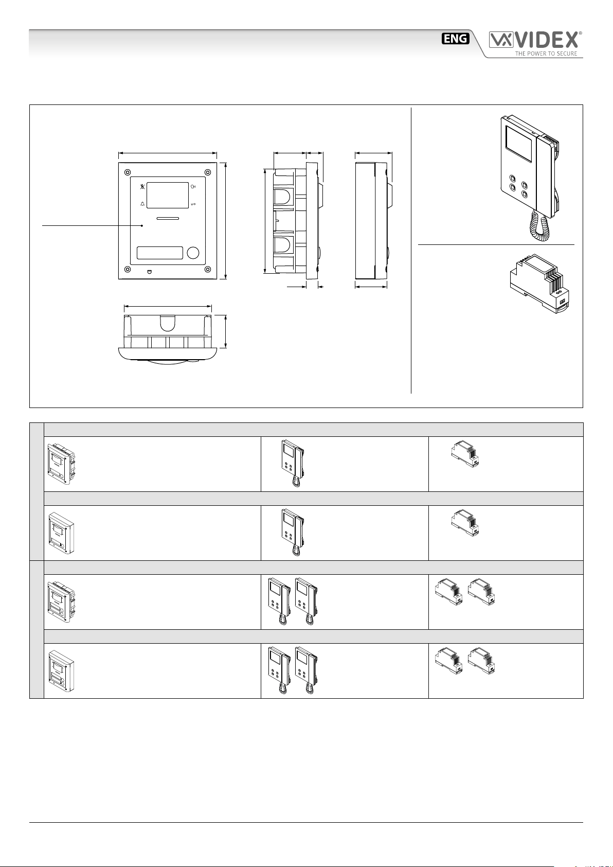
System components and available versions
IPVK/6296
OUTDOOR
STATION
Camera unit
Art.4533
pag. 5
Fig. 1 - IPVK/6296 components (measures in mm)
Colour videokit.
135,0
120,0
160,0
45,0
45,0 22,7
143,0
15,7
Flush
Mounting
50
43,8
Surface
Mounting
INDOOR
STATION
Videophone
Art.6296
pag. 14
ACCESSORIES
Power supply
Art.DR-15-12
IPVK-1/6296 - ush mounting
1 Outdoor station composed of:
1 Art.4533-1: 1 button camera unit
1 Art.4851: Flush mounting box
IPVK-1S/6296 - surface mounting
1 Outdoor station composed of:
ONE WAY VERSIONS
IPVK-2/6296 - ush mounting
IPVK-2S/6296 - surface mounting
TWO WAY VERSIONS
1 Art.4533-1: 1 button camera unit
1 Art.4881: Surface mounting box
1 Outdoor station composed of:
1 Art.4533-2: 2 buttons camera unit
1 Art.4851: Flush mounting box
1 Outdoor station composed of:
1 Art.4533-2: 2 buttons camera unit
1 Art.4881: Surface mounting box
1 Colour videophone
Art.6296
1 Colour videophone
Art.6296
2 Colour videophones
Art.6296
2 Colour videophones
Art.6296
1 Power supply
Art.DR-15-12
1 Power supply
Art.DR-15-12
2 Power supplies
Art.DR-15-12
2 Power supplies
Art.DR-15-12
IPVK/6296 Series - Installation handbook
- 3 -
66550062-EN - V 1.1 - 31/05/18
Page 4
IPVK/6296 Series IP videokit
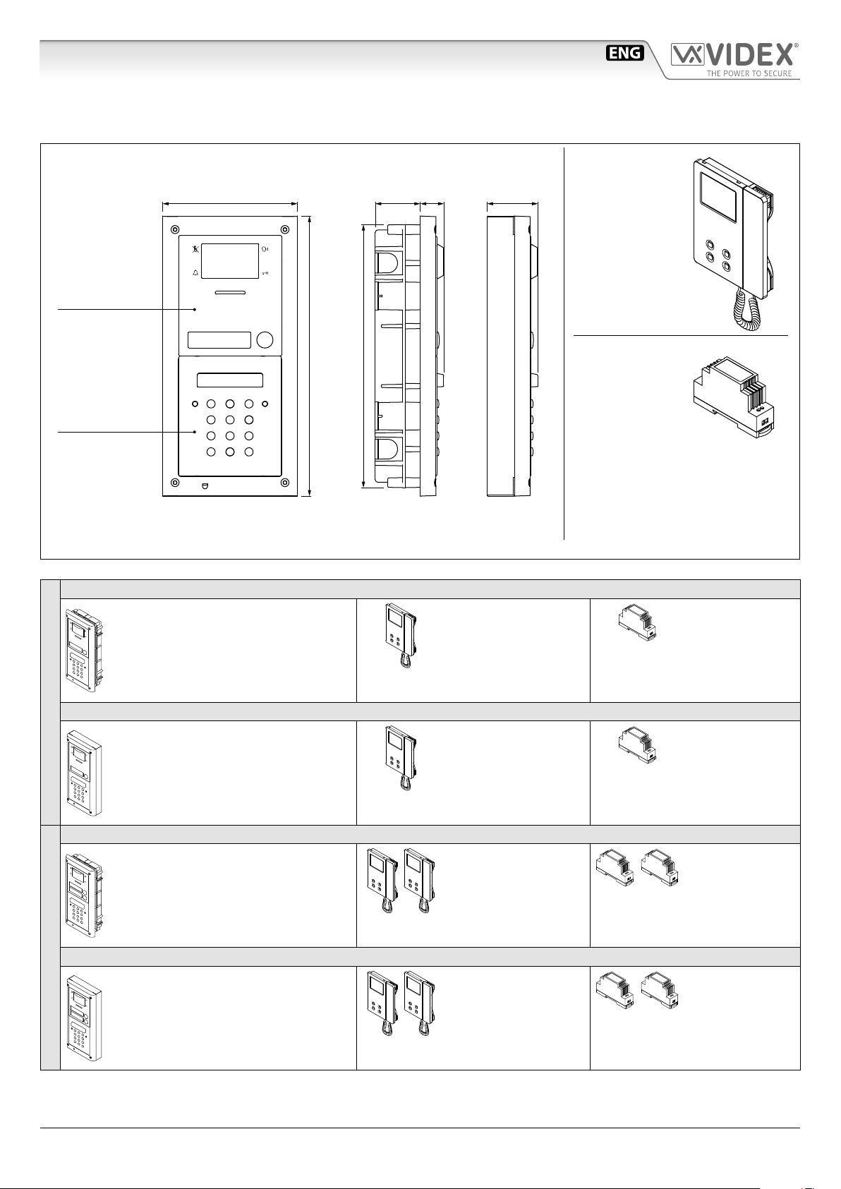
System components and available versions
IPVKC/6296 Colour videokit plus a codelock module.
OUTDOOR
STATION
Camera unit
Art.4533
pag. 5
Codelock
module
Art.4800M
pag. 9
Fig. 2 - IPVKC/6296 components (measures in mm)
280,0
45,0 24,0
263,0
Flush
Mounting
51,0135,0
Surface
Mounting
INDOOR
STATION
Videophone
Art.6296
pag. 14
ACCESSORIES
Power supply
Art.DR-15-12
IPVKC-1/6296 - ush mounting
1 Outdoor station composed of:
1 Art.4533-1: 1 button camera unit
1 Art.4800M: Codelock module
1 Art.4852: Flush mounting box
IPVKC-1S/6296 - surface mounting
1 Outdoor station composed of:
ONE WAY VERSIONS
IPVKC-2/6296 - ush mounting
IPVKC-2S/6296 - surface mounting
TWO WAY VERSIONS
1 Art.4533-1: 1 button camera unit
1 Art.4800M: Codelock module
1 Art.4882: Surface mounting box
1 Outdoor station composed of:
1 Art.4533-2: 2 buttons camera unit
1 Art.4800M: Codelock module
1 Art.4852: Flush mounting box
1 Outdoor station composed of:
1 Art.4533-2: 2 buttons camera unit
1 Art.4800M: Codelock module
1 Art.4882: Surface mounting box
1 Colour videophone
Art.6296
1 Colour videophone
Art.6296
2 Colour videophones
Art.6296
2 Colour videophones
Art.6296
1 Power supply
Art.DR-15-12
1 Power supply
Art.DR-15-12
2 Power supplies
Art.DR-15-12
2 Power supplies
Art.DR-15-12
IPVK/6296 Series - Installation handbook
- 4 -
66550062-EN - V 1.1 - 31/05/18
Page 5
IPVK/6296 Series IP videokit
Art.4533 IP speaker unit module for VIDEX IP System
G
H
A
B B
C
4533-0
4533-1
4533-2
STEEL
ALI
HIGH BRASS
Made in Italy
Close
Open
RESET?
I
J
K
V
JP1
GND
B
A
RS485
EXPANSION
EXT CAMERA
BUTTONS
SL
L
TIA/EIA-568-A.1-2001 T56AB
Wiring
White-Green
Green
White-Orange
Blue
White-Blue
Orange
N
White-brown
Brown
Fig. 1
GND
POWER
RELAY 2 INPUTS
NC1
ETHERNET
NO2
NC2
TX+
C1
C2
TX–
RX+
RX–
PTE2
GNDP
PTE1
GND
+12V
RELAY 1
NO1
D
E
M
Orange-whiteGreen
Orange
White-green
Fig. 2
F
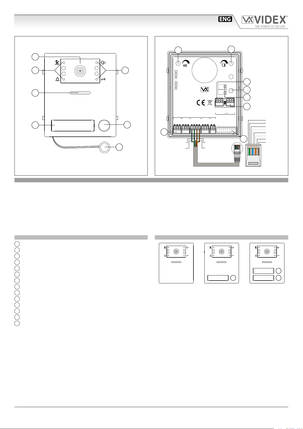
DESCRIPTION
IP speaker unit module with built-in wide colour day/night camera with autoiris lens and IR illumination LEDs. Depending on the
speaker unit version it includes one or two call push buttons. The unit circuitry incorporates:
• The transmitting amplier with microphone and volume control;
• The receiving amplier with volume control;
• Two enslavement relay to enable electric locn and an additional service (3 contacts each: common, normally open and normally closed).
• The call buttons from 1 to a maximum of 2 depending on the module version;
• The illumination LEDs for the card name holder;
• The camera comprised of illumination LEDs.
MODULE DETAILS:
A
Camera with illumination LEDs;
B
Operation LEDs;
C
Loudspeaker;
D
Card name holder;
E
Call push button (0, 1 or 2 depending on the model);
F
Microphone;
G
Loudspeaker volume control;
H
Microphone volume control;
I
RS485 connection terminals;
J
Boot loader push button for rmware update;
K
RS485 termination jumper;
L
External camera connection terminals;
M
System connection terminals;
N
Button expansion modules connector
AVAILABLE MODULE VERSIONS
Art.4533-0 Art.4533-1 Art.4533-2
IPVK/6296 Series - Installation handbook
- 5 -
66550062-EN - V 1.1 - 31/05/18
Page 6
IPVK/6296 Series IP videokit
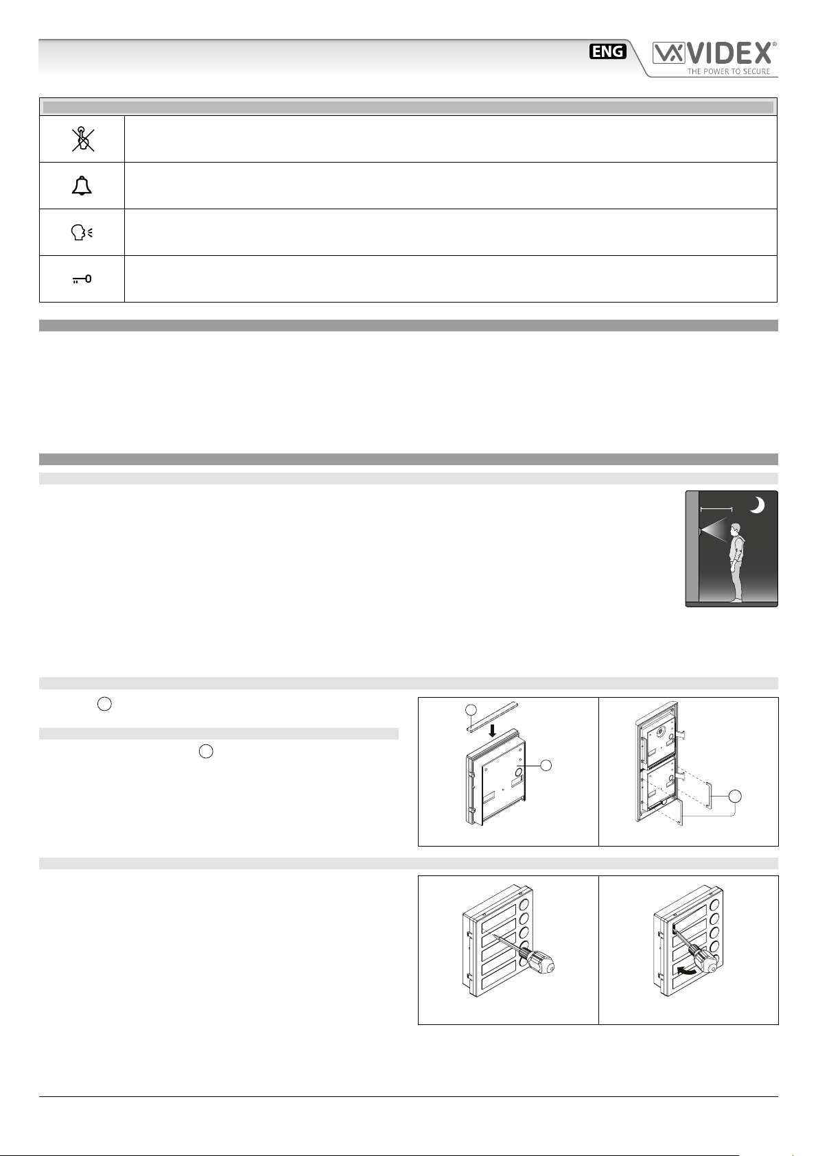
MAX 50 cm
Art.4533 IP speaker unit module
FRONT LEDS SIGNALLING DESCRIPTION
Flashes when the called indoor station is busy is busy. The LED will be o when the system is in stand-by,
If illuminated, indicates that the call from the outdoor station is in progress. The LED will switch OFF when the call
is answered or expired the call time without any answer.
If illuminated, indicates that it is possible to speak because the call has been answered. The LED will switch OFF at
the end of a conversation (or at the end of the conversation time).
If illuminated, indicates that the door lock has been operated. It will switch OFF at the end of the programmed
“door opening” time.
PROGRAMMING
The programming of the module is carried out through the VIDEX IP Wizard software.
Directly on the module are allowed some adjustments:
• Microphone volume through the relevant trimmer;
• Loudspeaker volume through the relevant trimmer;
• RS-485 connection termination.
For the module programming refer to the section VIDEX IP Wizard.
GENERAL DIRECTIONS FOR MODULE INSTALLATION
MAXIMUM ILLUMINATION DISTANCE FROM CAMERA AT NIGHT
The IR LED’s within the camera will illuminate the visitor when they are within 50cm of the camera.
ADHESIVE GASKET PLACEMENT
Apply the Y seal as shown in Fig. 3.
Y
ANTITAMPERING LOCKS FIXING
W
Fit the anti-tampering locks
as shown in Fig. 4.
G
Fig. 3
W
Fig. 4
HOW TO REMOVE/INSERT THE CARD NAME HOLDER
• To avoid damage to the module front plate, mask the side that
will be in contact with the screwdriver blade;
• Insert the screwdriver (at side) into the card-holder hole as
shown in Fig. 5;
• Move the screwdriver to the left as shown in Fig. 6 to extract
the card name holder;
• Edit the card name then replace it inside the holder and ret:
insert the holder inside its housing from the left or right side
then push the other side until it clips into place.
IPVK/6296 Series - Installation handbook
Fig. 5 Fig. 6
- 6 -
66550062-EN - V 1.1 - 31/05/18
Page 7
IPVK/6296 Series IP videokit
Art.4533 IP speaker unit module
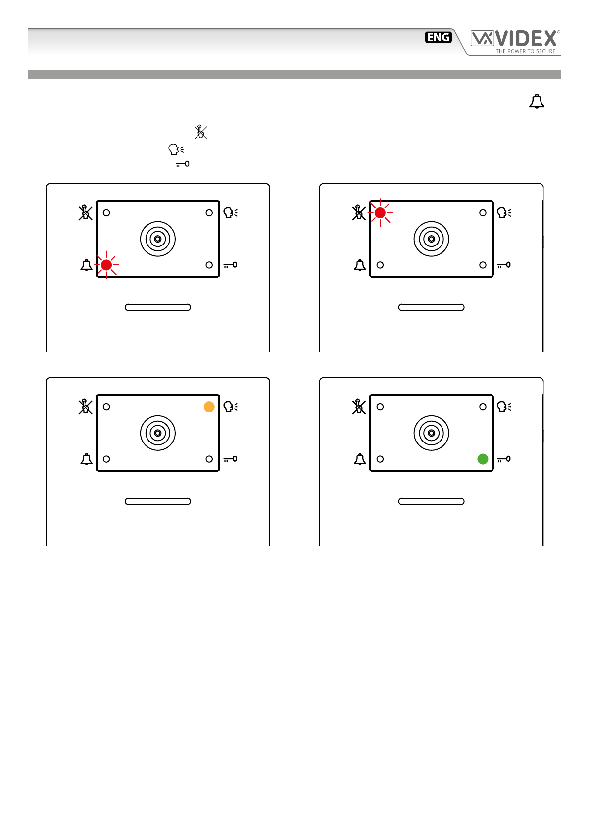
OPERATION
The system operation is supported by the built-in LED.
• When a visitor press a call button the units emits an intermittent deep call tone and in correspondence with the tone the
LED ashes (Fig. 7) until the resident answer or the programmed call time expires.
• If the called indoor station is busy the
• When the resident answers, the
• If the resident open the door, the
Fig. 7 Call in progress Fig. 8 Calling a busy indoor station
red LED ashes (Fig. 8) 4 times quickly and the unit emits a deep tone on each ash.
yellow LED (Fig. 9) illuminates and remains illuminated until the conversation terminates.
green illuminates (Fig. 10) for the programmed door opening time.
red
Fig. 9 The conversation is in progress Fig. 10 Door opening
IPVK/6296 Series - Installation handbook
- 7 -
66550062-EN - V 1.1 - 31/05/18
Page 8
IPVK/6296 Series IP videokit
Art.4533 IP speaker unit module
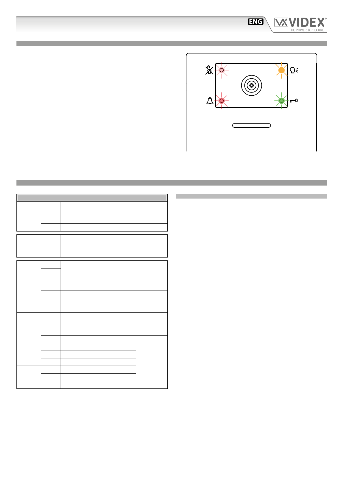
ENABLE BOOTLOADER MODE
In case of rmware update failure (i.e. because of mains failure or
cable disconnection during the update etc.) and the door panel is
not anymore recognized by the Videx IP Wizard software, you can
try to restore it by manually putting it into boot mode.
It is strongly recommended that this operation is carried out by
a qualied engineer and in any case after a contact with videx
support.
• Disconnect the door panel from the power supply.
• Press and keep pressed the “J” button (Fig. 2 on page 5) then
connect again the power supply source.
• The door panel goes in boot mode recognized by the four
LEDs ashing alternatively (Fig. 11).
• Now proceed using the utility “VidexFirmwareUpdater.exe” to
upload the rmware to the device.
• If the update process terminates correctly, the device should
be restored and ready to work.
• If the device still not work, please contact the supplier to proceed according to the warranty terms.
TECHNICAL SPECIFICATION
Fig. 11 Door panel in BOOTLOADER mode
SIGNALS ON SYSTEM CONNECTION TERMINALS
Active low output enabled when the
SL
EXT
CAMERA
RS485
POWER
INPUTS
ETHERNET
RELAY 2
RELAY 1
GND Composite video signal ground reference
GND
+12V
GND
PTE1
PTE2
GNDP Ground reference to be used with PTE inputs
NO2 Relay 2 normally open contact
NO1 Relay 1 normally open contact
external video input is in use
V Composite video signal input
A
RS-485 Connection (termination adjusted
B
through the JP1 jumper)
12Vdc 400mA power supply input
Active low input 1 (when enabled activate
the relay 1)
Active low input 2 (when enabled activate
the relay 1)
RX– Ethernet Connection Orange (568A)
RX+ Ethernet Connection White/Orange (568A)
TX– Ethernet Connection Green (568A)
TX+ Ethernet Connection White/Green (568A)
C2 Relay 2 common contact
NC2 Relay 2 normally closed contact
C1 Relay 1 common contact
NC1 Relay 1 normally closed contact
UNIT SPECIFICATION
Housing/Mounting: One 4000 Series Module / 4000 Series
Modular System
Push Buttons: Yes, from 0 to 2 call buttons depend-
ing on the model
Programming: Yes, carried out by the 8 way dip-switch
located on the rear of the module
Controls: Microphone and Loudspeaker volume
trimmers
Front plate nishes: Mirror stainless steel (standard),
Anodized Aluminium (add /a after the
product code) or High Brass (add /HB)
Power Supply: 12Vdc - 400mA
Power consumption: Stand-by: ?? mA
Operating: ?? mA
Working Temperature: -10 +50 °C
Max
12-24
Vac/dc
0.4A
IPVK/6296 Series - Installation handbook
- 8 -
66550062-EN - V 1.1 - 31/05/18
Page 9
IPVK/6296 Series IP videokit
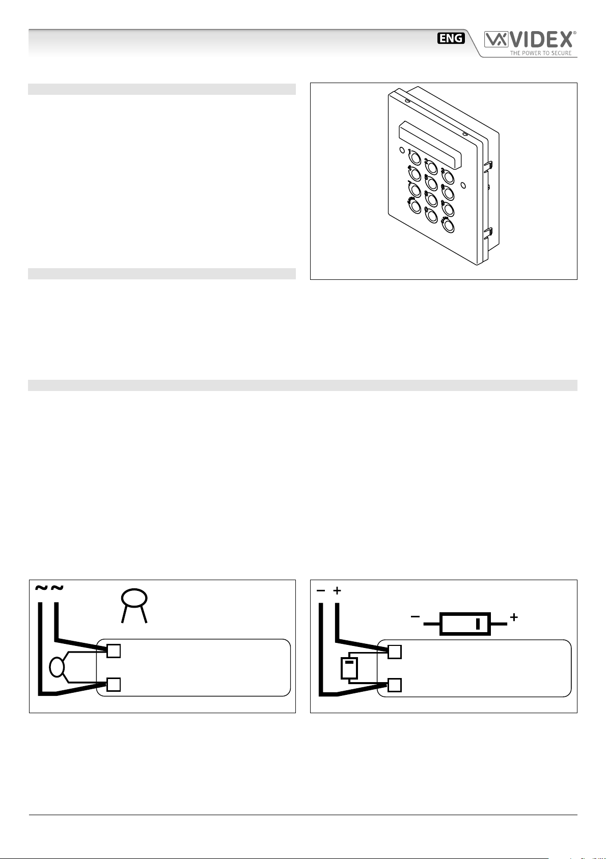
LOCK RELEASE BACK EMF PROTECTION
A varistor must be tted across the terminals on AC lock release
and a diode must be tted across the terminals on a DC
lock release
DIODE
Art.4800M Digital codelock module
CODELOCK UNIT MODULES ART.4800M
The module features 12 stainless steel buttons (Keys 0 - 9,
ENTER and CLEAR), 2 LED’s for progress information during
use and programming and a mirror nish stainless steel front
plate (Standard version). With three integral relays each with
common, normally open and normally closed connections and
two inputs to enable the external triggering of relays one and
two (For example, push to exit button). Key presses are signalled
both acoustically and visually while each button press has a tactile feel. Entering the correct code followed by ENTER will activate the relevant relay. Programming is carried out through
the same keypad following a simple programming menu. The
module can be combined with other 4000 Series modules in an
audio or video intercom system.
MAIN FEATURES
• 3 C, NC, NO relay outputs (24Vac/dc – 5A max);
• 3 Programmable secret codes (one for each relay);
• Each relay can be set to be activated for a specic time (01 to 99 seconds) or to work as latch;
• Two active low inputs to command directly the relay 1 and 2;
• Programming menu guarded by a 4-8 digit programmable engineer’s code;
• Visual and Acoustic signal during operating and programming;
• Keypad illumination LEDs;
GENERAL DIRECTIONS FOR INSTALLATION
In order to achieve the best results from the schematics described it is necessary to install only original VIDEX equipment, strictly
keeping to the items indicated on each schematic and follow these General Directions for Installation:
• The system must be installed according to national rules in force, in any case the running of cables of any intercom unit must be
carried out separately from the mains;
• All multipair cables should be compliant to CW1308 specication (0.5mm twisted pair telephone cable).
• Cables for speech line and service should have a max resistance of 10 Ohm
• Lock release wires should be doubled up (Lock release wires and power supply wires should have a max resistance of 3 Ohm);
• The cable sizes above can be used for distances up to 50m. On distances above 50m the cable sizes should be increased to keep
the overall resistance of the cable below the RESISTANCES indicated above;
• Double check the connections before power up;
• Power up the system then check all functions.
(Fig.1B) to suppress back EMF voltages. Connect the components to the lock releases as shown in gures.
Fig. 1 - Art.4800M
(Fig.1A)
VARISTOR (MOV)
12V AC
LOCK RELEASE
Fig.1A
IPVK/6296 Series - Installation handbook
1N4002
12V DC
LOCK RELEASE
Fig.1B
- 9 -
66550062-EN - V 1.1 - 31/05/18
Page 10
IPVK/6296 Series IP videokit
Art.4800M Digital codelock module
BUZZER BACK EMF
When using intercoms with buzzer call (Art.924/926, SMART1/2, 3101/2, 3001/2 and 3021/2) add one 0.1uF (100nF) capacitor between terminals 3 and 6 on the telephone.
BUILTIN RELAYS BACK EMF PROTECTION
The Art.4800M includes selectable back EMF protection on the relays. The jumpers marked MOV (One jumper for each relay) are
used to select the protection type. When using a fail secure lock with connections C & NO the jumper should be in the NO position.
When using a fail open lock with connections C & NC the jumper should be in the NC position and when using the codelock to
trigger a gate controller or another third party controller the jumper should be removed completely (This disables the protection
on the relay).
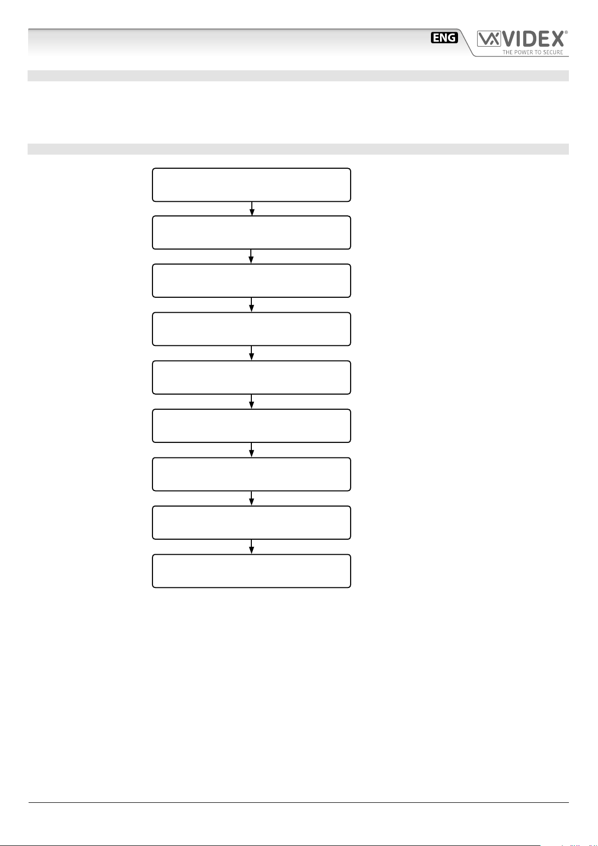
PROGRAMMING SEE ALSO THE RELEVANT FLOW CHART
• Enter the “ENGINEER’S CODE”: rst time type six times “1” (111111 factory preset) and press “ENTER” (The red LED will illuminate);
• Conrm “ENGINEER’S CODE” (typing again the same) or type the new code (4 to 8 digits) then press “ENTER” (Melody). Pressing
twice the “ENTER” button without changing the “ENGINEER’S CODE”, will exit from the programming;
• Enter the code (4 to 8 digits) to enable “RELAY 1” or re-enter the existing code then press “ENTER” (Melody);
• Enter the “RELAY 1” operation time (2 digits 01 to 99 I.E. 05=5 seconds, 00= remain open time) or re-enter the existing time then
press “ENTER” (Melody);
• Enter the code (4 to 8 digits) to enable “RELAY 2” or re-enter the existing code then press “ENTER” (Melody);
• Enter the “RELAY 2” operation time (2 digits 01 to 99 I.E. 05=5 seconds, 00= remain open time) or re-enter the existing time then
press “ENTER” (Melody);
• Enter the code (4 to 8 digits) to enable “RELAY 3” or re-enter the existing code then press “ENTER” (Melody);
• Enter the “RELAY 3” operation time (2 digits 01 to 99 I.E. 05=5 seconds, 00= remain open time) or re-enter the existing time then
press “ENTER” (Melody);
• The system is ready to use (the red LED will be o ).
PROGRAMMING NOTES
• After pressing enter following a command, press “ENTER” a further twice to exit the programming menu.
RETURN SYSTEM TO PRESET ENGINEER’S FACTORY CODE
• Turn o power to code lock;
• Keep “ENTER” button pressed while turning the power back on;
• Release “ENTER” button;
• The engineer’s code is now set to “111111” (six times one).
OPERATION
• Type in the programmed code and press “ENTER”;
• If the code is correct, the green LED will illuminate for ap-
prox. 2 seconds and the relay relevant to the code will operate for the programmed time;
• If a wrong code is entered, a continuous melody will sound
for 4 or more seconds, according to the number of mistakes;
• To switch o any relay while operating, type in the relevant
code then press the “CLEAR” button;
OPERATION NOTES
• To operate relays together, set the same code for each relay;
• If a wrong code is entered, the system will lock out for 5 sec-
onds which will increase each time a wrong code is entered.
The system will operate only when the correct code is entered.
TERMINALS:
SW2 Relay 2 command signal (active low)
SW1 Relay 1 command signal (active low)
NC3 Relay 3 normally closed contact
NO3 Relay 3 normally open contact
C3 Relay 3 common contact
NC2 Relay 2 normally closed contact
NO2 Relay 2 normally open contact
C2 Relay 2 common contact
NC1 Relay 1 normally closed contact
NO1 Relay 1 normally open contact
C1 Relay 1 common contact
+
12/24Vac/dc power input
Max
24Vac/dc
3A
IPVK/6296 Series - Installation handbook
- 10 -
66550062-EN - V 1.1 - 31/05/18
Page 11
IPVK/6296 Series IP videokit
Art.4800M Digital codelock module
TECHNICAL SPECIFICATION
Power Supply: 12/24 Vac/dc – 2VA
Power Consumption: Stand-by: 20mA
Operating: 70mA
Working Temperature: -10 +50° C
PROGRAMMING FLOWCHART
Red LED will be ON
Melody
Melody
Melody
Melody
Melody
Melody
Melody
ENTER “ENGINEER’S CODE“
AND PRESS “ENTER“
CONFIRM OR CHANGE “ENGINEER’S CODE“
AND PRESS “ENTER“
ENTER “ACCESS 1 CODE“
AND PRESS “ENTER“
ENTER “ACCESS 1 TIME“
AND PRESS “ENTER“
ENTER “ACCESS 2 CODE“
AND PRESS “ENTER“
ENTER “ACCESS 2 TIME“
AND PRESS “ENTER“
ENTER “ACCESS 3 CODE“
AND PRESS “ENTER“
ENTER “ACCESS 3 TIME“
AND PRESS “ENTER“
First time 6 times 1 "111111"
factory preset
Type again six times “1”
or the new enginner’s code 4 to 8 digits
Code to enable
relay 1
4 to 8 digits
2 digits (01 to 99)
I.E. 05 = 5 seconds
00 = remain open time
Code to enable
relay 2
4 to 8 digits
2 digits (01 to 99)
I.E. 05 = 5 seconds
00 = remain open time
Code to enable
relay 3
4 to 8 digits
2 digits (01 to 99)
I.E. 05 = 5 seconds
00 = remain open time
Red LED will be OFF
IPVK/6296 Series - Installation handbook
SYSTEM READY TO USE
- 11 -
66550062-EN - V 1.1 - 31/05/18
Page 12
IPVK/6296 Series IP videokit
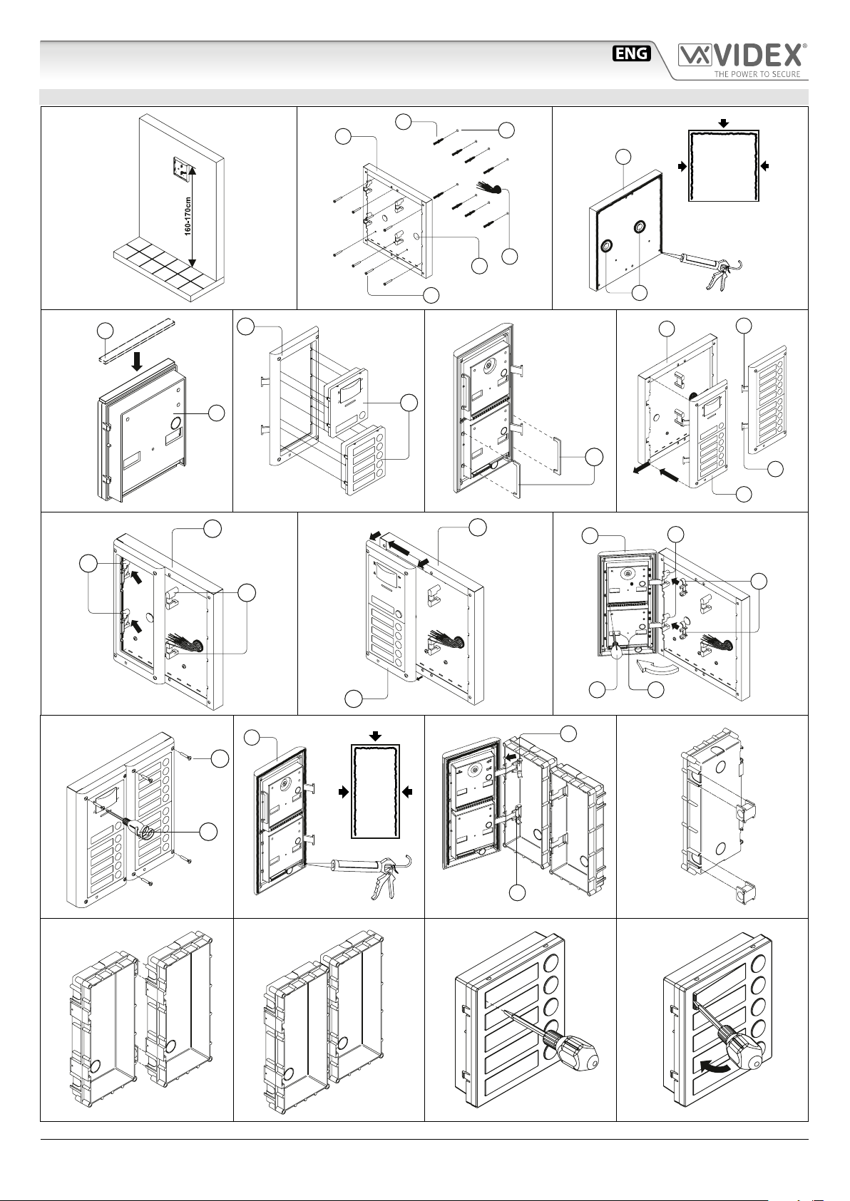
4000 Series Surface and ush mounting door station installation
EXAMPLE: INSTALLING A FOUR MODULE OUTDOOR STATION
B
C
g. 1
Y
H
G
F
G
g. 4 g. 5 g. 6 g. 7
C
A
C
E
D
g. 2
W
C
H
D
C
M
g. 3
L
L
H
M
N
g. 10
g. 14
Q
P
g. 11
M
g. 8
H
H
g. 9
N
g. 12
P O
N
g. 13
g. 15
IPVK/6296 Series - Installation handbook
g. 16
- 12 -
g. 17
g. 18
66550062-EN - V 1.1 - 31/05/18
Page 13
IPVK/6296 Series IP videokit
4000 Series Surface and ush mounting door station installation
INSTALLING A SURFACE MOUNT DOOR STATION
1. Place the surface box against the wall (165-170cm between the top of the box and the oor level as shown in Fig.1) and mark the xing holes for
the wall plugs and the hole for the cables
In order to prevent water ingress we highly recommend using a silicon sealant between the wall and the back box C
ON THE LEFT, TOP AND RIGHT SIDES ONLY AND AROUND ALL HOLES D.
DON’T USE SILICON SEALANT ON THE BOTTOM SIDE OF THE BACK BOX (Fig.3);
2. As shown on Fig.2, drill the xing holes A, insert the wall plugs B and feed the cables E through the surface box opening D, x surface
3. Apply the
4. Before installation of the module support frame, hook the modules
5. When you have more than one support frame, hook the support frame to the surface box starting from the left. For convenience we will described
6. As shown on Fig. 9, pull back the module support frame
7. As shown in Fig. 10, open the module support frame
8. Repeat the same operations described above for the second module support frame (or for the third if available);
9. When the system has been tested and is working correctly, move back the module support frames carefully, x them to the surface box using the
C
to the wall using the screws F;
box
the two anti-tampering locks
Y
silicon sealant on top of each module as shown in Fig.4;
W
for each module (do the same for the second module support frame);
how to attach the left frame but the same must be carried out for the right frame. As shown in Fig. 7, hook the module support frame
with modules) to the surface box
M
as shown in Fig. 8;
C
required connections using the screwdriver provided
O
openings
screwdriver provided
) and adjust trimmers;
P
(torx end) and the pin machine torx screws Q (Fig. 11). Note: do not over tighten the screws more than is necessary.
E
(g.2). Observe the orientation of the box with the hinge on the left;
G
to the support frame H as shown in Fig.5 then, as shown in Fig. 6, t
H
(complete
moving the frame as suggested from pointers. Ensure that the pivots L (Fig. 7) go inside the relevant housing
H
while moving it slightly to the left as suggested by the pointers;
H
as suggested by the pointer, hook the hinge locks N to the hinges M, make the
P
(at blade end) and make the required adjustment by adjusting the settings (through
INSTALLING A FLUSH MOUNTING DOOR STATION
When ush mounting and the number of modules is greater than 3, the required back boxes need to be linked together (before embedding them
in the wall) as shown on Fig. 14, 15 and 16:
• Arrange the back boxes and remove knockouts to allow cables to be fed from one back box to the other;
• Hook the spacers to rst back box then hook the second back box to obtain the result shown on Fig. 16;
1. Protect the module support frame xing holes from dust then embed the back box into the wall (165-170cm between the top of the box and
the oor level as shown on the Fig. 1) feeding the cables
E
(Fig. 2) through a previously opened hole in the box. Observe the direction of the
box ensuring the hinge is on the left and take care that the box prole is in line with the nished wall prole;
In order to prevent water ingress we highly recommend using a silicon sealant between the module support frame
H
and the back box ON THE LEFT, TOP AND RIGHT SIDES ONLY.
DON’T USE SILICON SEALANT ON THE BOTTOM SIDE OF THE MODULE SUPPORT FRAME (Fig.12);
2. Continue from step 4 of surface mounting instructions , but at step 7 hook the hinge locks N as shown on Fig. 13.
Note: if additional holes are made in the surface box, oxidation problems may appear unless the unprotected metal is
coated with a protective paint.
NOTES
• The screwdriver’s blade has two sides, one at and one torx, to select one of them unplug the blade from the screwdriver body and plug it
into the required side.
• The example shows the use of only one back box bottom hole for wires, this is done to keep le drawings clear. Naturally the installer can use
the left hole or the right or both if required.
HOW TO REMOVE THE CARD NAME HOLDER
• To avoid damage to the module front plate, tape the side that will be in contact with the screwdriver blade;
• lnsert the screwdriver (at side) into the card-holder hole as shown in Fig. 17;
• Move the screwdriver to the left as shown in Fig. 18 to extract the card name holder;
• Edit the card name then replace it inside the holder and ret: insert the holder inside its housing from the left or right side then push the other
side until it clips into place.
IPVK/6296 Series - Installation handbook
- 13 -
66550062-EN - V 1.1 - 31/05/18
Page 14
IPVK/6296 Series IP videokit
Art.6296 IP Videophone for VIDEX IP System
27 mm 144 mm
A
B
182 mm
GNDP
PTE2
PTE1
F
OUT2
OUT2
OUT1
OUT1
+12
GNDAB
GND
I
E
L
C D
Fig. 1
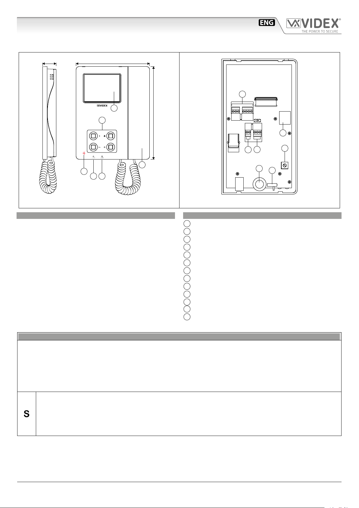
DESCRIPTION
IP Videophone specic for VIDEX IP System using 3.5” full colour
active matrix LCD touch screen.
The videophone includes 4 buttons with standard functions like
“privacy”, “door- open”, “camera recall” and “service” plus 5 LED’s
for visual indication of all functions.
Adjustments: manual control for call tone volume on 3 levels
(low, medium, high) and picture brightness.
Programmable options: call tone melody, number of rings, privacy duration, date & time.
Intercommunication, Video Memory and Event log management are further features include.
The Art.6296 is surface mount.
H
G
J
M
K
Fig. 2
LEGEND
A
3,5” Touch screen
B
Operating push buttons and LED’s
C
Call tone volume control
D
Brightness control
E
Handset
F
Input/output terminals (not used)
G
12Vdc power supply input (for non POE installations)
H
RS-485 Interface
I
POE Ethernet interface
J
Brightness control
K
Call tone volume control (3 levels)
L
Red LED to advice a missed call from door panel
M
Microphone potentiometer (it increases the volume from
the handset to the door panel loudspeaker)
PUSH BUTTONS
The button operation depends on the conguration carried out through the conguration software for VIDEX IP system “Videx IP
Wizard”.
Default button functions can be changed, the function of the button can be dierent depending on the current state of the videophone.
• “In Stand- by” when the system is not in use.
• “Ringing” during an incoming call.
• “In Conversation” during a conversation between the resident and the visitor.
Service push button
It is possible to set two dierent operating modes according to the system status: “In Stand-by”, “In Conversation”.
• “In Stand-by” the button can be congured to trigger a specic relay of a specic door panel.
• “In Conversation” the button can be congured to trigger a specic relay of a specic door panel or the rst or second
relay of the active door panel.
As default, this button is disabled in both operating states.
IPVK/6296 Series - Installation handbook
- 14 -
66550062-EN - V 1.1 - 31/05/18
Page 15
IPVK/6296 Series IP videokit
Art.6296 IP Videophone for VIDEX IP System
PUSH BUTTONS
Privacy ON-OFF push button
It is possible to set two dierent operating modes according to the system status: “In Stand-by”, “In Conversation”.
• “In Stand-by” it can only be used as a “privacy on-o” button. Press to activate (privacy LED illuminates) or press to
deactivate (privacy LED goes o ).
• “In Conversation” the button can be congured to trigger a specic relay of a specic door panel or the rst or second
relay of the active door panel.
As default, the privacy is set to “Innite” and the button is disabled for the “In Conversation” state.
The button operates also as video source switch, during the conversation, keep pressed until the video source switches from
the module built-in camera video signal to the external video source and viceversa. When the door panel is set for an external
video source, it is also possible to set the default video signal source (internal or external) transmitted during a call.
By pressing this button while the videophone is ringing, the call is rejected.
Door open push button
It is possible to set one operating mode for both the statuses “Ringing” and“In Conversation”.
• “In Conversation” & “Ringing” the button can be congured to trigger a specic relay of a specic door panel or the rst
or second relay of the active door panel.
In Stand-by, when pressed, starts an intercommunicating call with the videophone set as preferred.
As default, the button activates the “relay 1” of the active door panel.
Camera recall push button
The operation of this button cannot be customised, it works as a camera recall button during Stand-by.
During a camera recall session, the speech toward the door panel is disabled, to enable the speech, keep this button
pressed until the speech is enabled.
When pressed momentarily it takes a picture from the image shown.
LEDS
Privacy on LED
It illuminates when the privacy service is enabled.
CONTROLS
Call tone volume control
3 level switch.
Brightness control
Sliding wheel.
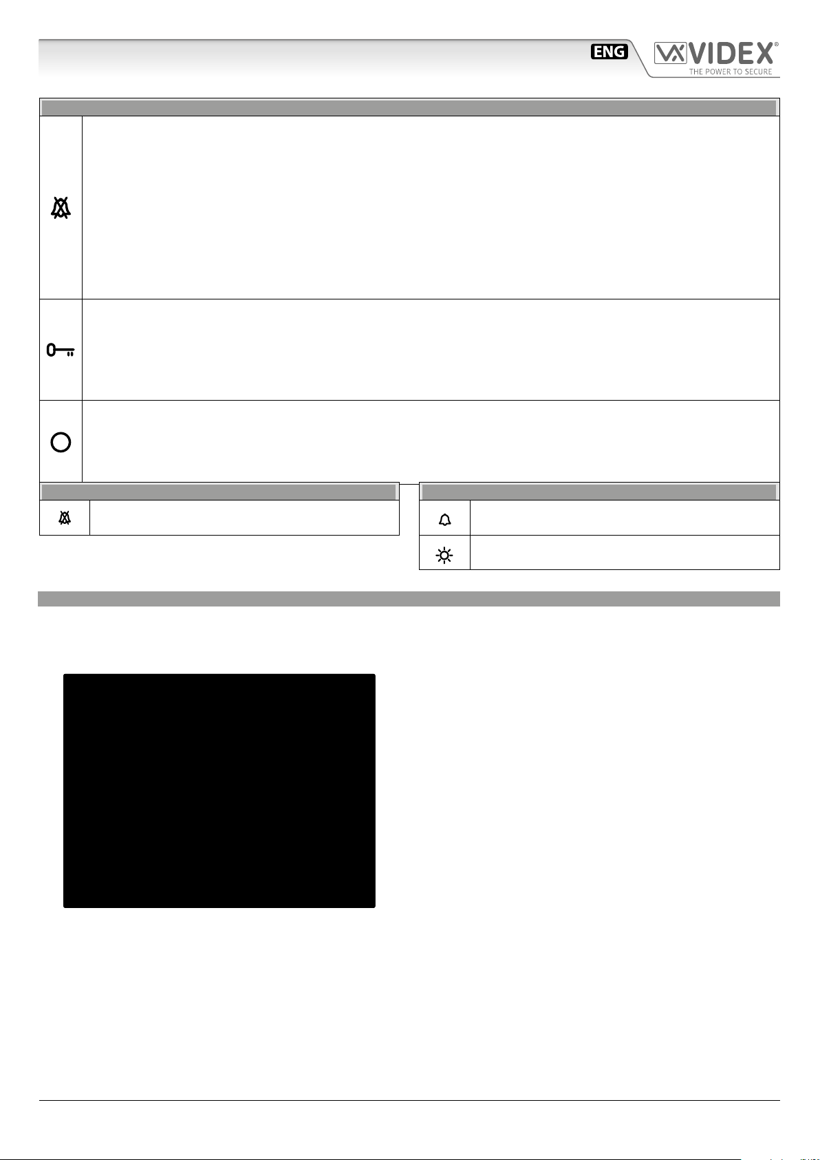
VIDEOPHONE INITIALISATION
If powering on the videophone (through a POE switch/router or an external power supply unit) the display shows the message
“DEVICE NOT INITIALISED” (Fig. 3), use the conguration software for VIDEX IP system (Videx IP Wizard.exe) to set the device and the
system.
DEVICE NOT INITIALISED
Please, use Videx IP Wizard
to set the device
Fig. 3 Device not initialised
IPVK/6296 Series - Installation handbook
- 15 -
66550062-EN - V 1.1 - 31/05/18
Page 16
IPVK/6296 Series IP videokit
Art.6296 IP Videophone for VIDEX IP System
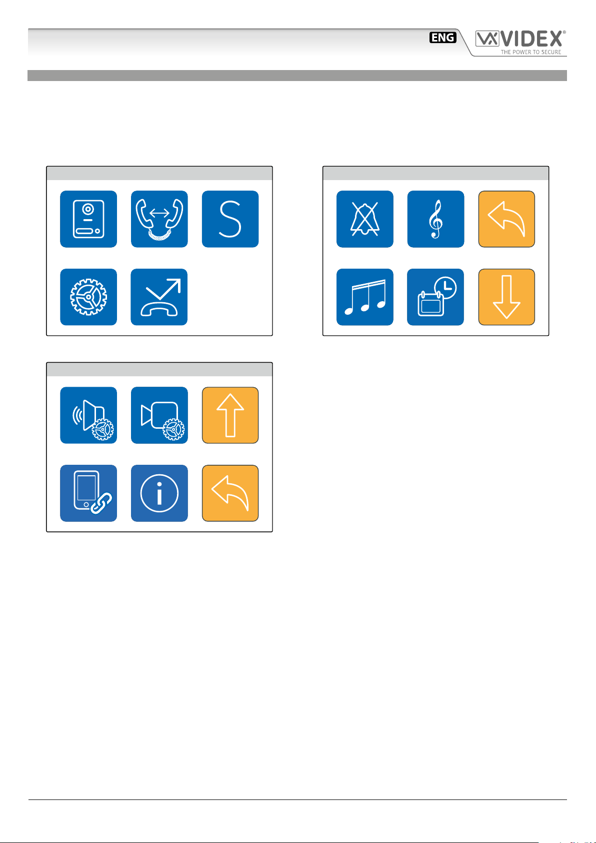
PROGRAMMING
The button operation must be programmed through the conguration software for VIDEX IP system while some operating parameters can be programmed through the videophone on screen menu. The “SETTINGS MENU” can be used to program some parameters and to carry out some adjustments.
• Programmable settings are: Privacy duration, Melody, Number of Rings and Date & Time (Fig. 5)
• Adjustable settings are: Speech quality toward a door panel, Video quality toward a door panel
If the screen is black, rst tap on it to see the main menu (Fig. 4) then tap on the gear icon to open the settings menu (Fig. 5)
MAIN MENU
Fig. 4 Main menu
SETTINGS MENU
15:30
15:30
SETTINGS MENU
Fig. 5 Settings menu 1/2
15:30
Fig. 6 Settings menu 2/2
IPVK/6296 Series - Installation handbook
- 16 -
66550062-EN - V 1.1 - 31/05/18
Page 17
IPVK/6296 Series IP videokit
15:30
15:30
Art.6296 IP Videophone for VIDEX IP System
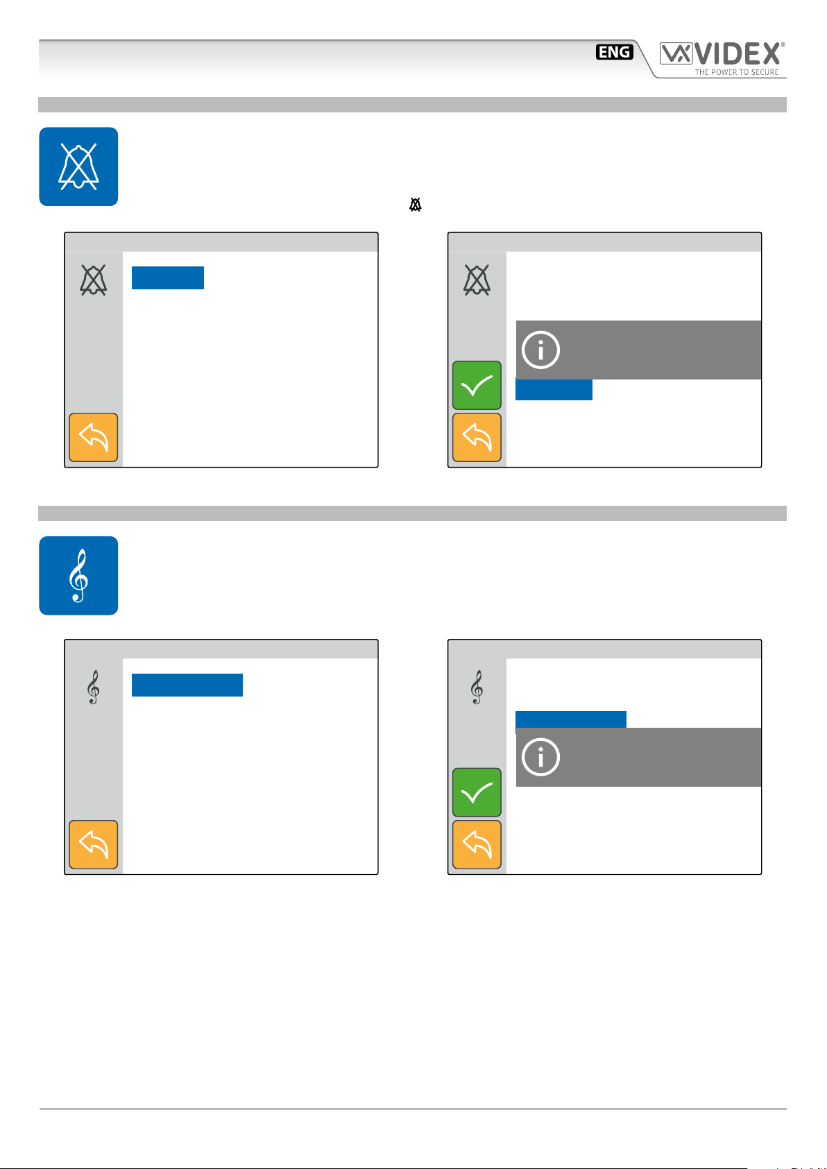
PRIVACY DURATION
• Tap on the privacy icon (Fig. 5 on page 16).
• The current value is shown (Fig. 7).
• Swipe among the values to select the required then tap on the tick button to conrm the value (Fig. 8).
• A notice will inform that the value is saved (Fig. 8).
• When the service is activated the relevant LED
illuminates.
SET PRIVACY DURATION
Innite
1 Hour
1.5 Hours
2 Hours
2.5 Hours
Fig. 7 Set privacy duration
MELODY
• Tap on the melody icon (Fig. 5 on page 16), the current melody is shown, tap on a melody to listen to it (Fig. 9)
then tap on the tick button to conrm the selected melody.
• A notice will inform that the value is saved (Fig. 10).
SET DEFAULT PRIVACY TIME
Innite
1 Hour
1.5 Hours
2 Hours
2.5 Hours
Fig. 8 Save the selected value
Saved
SET MELODY
15:30
Melody 1
Melody 2
Melody 3
Fig. 9 Listen the available melodies
SET MELODY
Melody 1
Melody 2
Melody 3
Fig. 10 Save the selected value
Saved
15:30
IPVK/6296 Series - Installation handbook
- 17 -
66550062-EN - V 1.1 - 31/05/18
Page 18
IPVK/6296 Series IP videokit
15:30
15:30
Art.6296 IP Videophone for VIDEX IP System
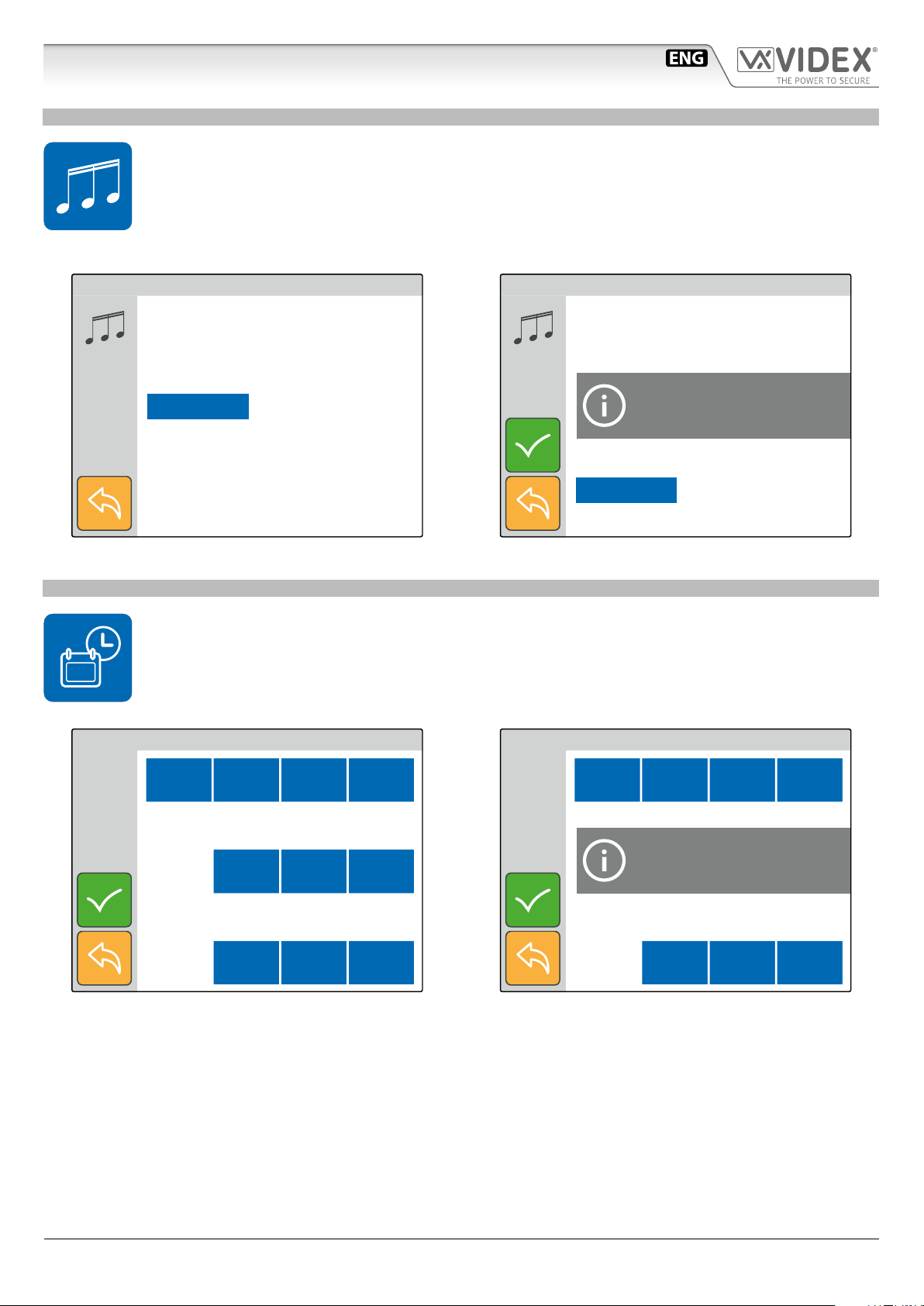
NUMBER OF RINGS
• Tap on the rings icon (Fig. 5 on page 16).
• The current value is shown (Fig. 11).
• Swipe among the values to select the required then tap on the tick button to conrm (Fig. 12).
• A notice will inform that the value is saved (Fig. 12).
Note, If the global call time is to short the full selected number of rings may not be heard.
SET NUMBER OF RINGS
15:30
3
4
5
6
7
Fig. 11 Select the number of rings
DATE & TIME
• Tap on the date & time icon (Fig. 5 on page 16)
• The current date & time is shown (Fig. 13).
• Operate the buttons to adjust the date & time required then tap on the tick button to conrm (Fig. 14).
• A notice will inform that the value is saved (Fig. 14).
SET NUMBER OF RINGS
3
4
5
Saved
6
7
Fig. 12 Save the selected value
15:30
SET DATE & TIME
14:52
+ Hour – Hour + Min – Min
+ Day + Month + Year
Tue 18 04/ / 17
+ Day + Month + Year
Fig. 13 Set the date & time
SET DATE & TIME
15:45
+ Hour – Hour + Min – Min
Tue 21 06/ / 17
Fig. 14 Save the value set
System Time Updated
+ Day + Month + Year
+ Day + Month + Year
IPVK/6296 Series - Installation handbook
- 18 -
66550062-EN - V 1.1 - 31/05/18
Page 19

IPVK/6296 Series IP videokit
Art.6296 IP Videophone for VIDEX IP System
ADJUST SPEECH QUALITY
• This setting is password protected (Fig. 15) because the adjustment will aect the entire installation.
• Tap on the speech adjustment icon (Fig. 6 on page 16).
• The default password is “9876”, type it then proceed with the adjustment.
• Select the door panel to connect to then tap the tick button to open the communication (Fig. 17).
• Adjust the speech operating on the plus and minus buttons of the various settings.
• Once a good speech level is obtained tap on the tick button to conrm (Fig. 18).
• A notice will inform that the adjustment is saved (Fig. 18).
ENTER ADMIN PASSWORD
15:30
7 8 9
4 5 6
1 2 3
0 C
Fig. 15 Enter engineer password
ADJUST AUDIO
+ –
+ –
+ –
LOCAL TH.
LOCAL ATT.
REMOTE TH. (300)
15:30
SELECT A CALL POINT
Main Entrance
Back Entrance
Fig. 16 Select the door panel to connect to
ADJUST AUDIO
+ –
+ –
+ –
LOCAL TH.
LOCAL ATT.
Saved
REMOTE TH. (300)
15:30
15:30
+ –
Fig. 17 Adjust the speech for the selected door panel
REMOTE ATT (51)
ECHO CANC ENABLED
+ –
Fig. 18 Save the speech adjustment
REMOTE ATT (51)
ECHO CANC ENABLED
IPVK/6296 Series - Installation handbook
- 19 -
66550062-EN - V 1.1 - 31/05/18
Page 20

IPVK/6296 Series IP videokit
Art.6296 IP Videophone for VIDEX IP System
ADJUST VIDEO QUALITY
• This setting is password protected (Fig. 19) because the adjustment will aect the entire installation.
• Tap on the video adjustment icon (Fig. 6 on page 16)
• The default password is “9876”, type it then proceed with the adjustment.
• Select the door panel to connect to then tap the tick button to open the communication (Fig. 21).
• Adjust the video operating on the plus and minus buttons of the various settings.
• Once a good video quality is obtained, tap on the save button to conrm (Fig. 21).
• A notice will inform that the adjustment is saved (Fig. 22).
ENTER ADMIN PASSWORD
15:30
7 8 9
4 5 6
1 2 3
0 C
Fig. 19 Enter engineer password
ADJUST VIDEO
Bright + Contr + Satur. + SAVE
15:30
SELECT A CALL POINT
Main Entrance
Back Entrance
Fig. 20 Select the door panel to connect to
ADJUST VIDEO
Bright + Contr + Satur. + SAVE
Outdoor Panel
Camera Settings
Saved
15:30
15:30
Bright – Contr – Satur. – EXIT
Fig. 21 Adjust the video for the selected door panel
BINDING CODE
• This menu option shows the binding code for the APP of your smartphone (iOS or Android) that allows you to
bind the videophone to the smartphone. After the binding process, any call directed to the videophone will be
received also on the smartphone. Once the APP is bound, the user can communicate with any door station on the
system.
• Tap on the binding code icon (Fig. 6 on page 16).
• The screen will show the “BINDING CODE” QR Code and text format (Fig. 23).
• Using a smartphone with an active data connection (connected to internet) launch the APP then tap on the plus symbol on the
top right corner (Fig. 24).
• Focus on the QR Code or enter the text code (Fig. 25) if you have diculties with the camera.
• After a short delay, if the binding is successful, the main screen of the APP should list the installation to which the videophone
is connected (Fig. 26). After this the APP is ready to work
Notes:
• The APP performances are strictly correlated to both the 3G /4G mobile data connection quality and the upload bandwidth of the internet connection available at the site where the system is
installed.
• The binding code is available only if the engineer that has installed the system has made the required online registration for the installed system.
IPVK/6296 Series - Installation handbook
- 20 -
Bright – Contr – Satur. – EXIT
Fig. 22 Save the video adjustment
66550062-EN - V 1.1 - 31/05/18
Page 21

IPVK/6296 Series IP videokit
15:30
Art.6296 IP Videophone for VIDEX IP System
LINK VIDEX APP
15:30
BINDING CODE:
93C2C369A9FEADCF9D16BFF18451EBDE
Fig. 23 Binding code
Scan the binding code
Videx Cloudnected
CONNECTED DEVICES CALL HISTORY
Fig. 24 Tap on “+” to bind the app with the videophone
Videx Cloudnected
CONNECTED DEVICES CALL HISTORY
Rickard’s home
Main Gate
4533
Back Gate
4533
BINDING CODE:
93C2C369A9FEADCF9D16BFF18451EBDE
Binding Code:
BIND
Fig. 25 Fit the QR Code in the frame or enter text code
DEVICE INFO
• This menu option is for information purposes.
• Tap on the device info icon (Fig. 6 on page 16).
• The monitor will show the device: model, name, ID, IP Address, MAC address, rmware version and hardware
version
DEVICE INFO
MODEL : VIDEX 6296
NAME : Ground Floor
ID :101
IP : 192.168.1.101
MAC : A0 : 56 : 11 : A5 : 64 : 21
15:30
Fig. 26 If the binding is successful the system is listed
FW VER : 0 . 1 . 0
HW VER : 1
Fig. 27 Device info
IPVK/6296 Series - Installation handbook
- 21 -
66550062-EN - V 1.1 - 31/05/18
Page 22

IPVK/6296 Series IP videokit
Art.6296 IP Videophone for VIDEX IP System
OPERATION VIDEOPHONE’S BUTTONS
TO ANSWER A CALL & OPEN THE DOOR
• On an incoming call the videophone rings and the display shows the initialising screen (Fig. 28) rst then shows the video coming from the door panel (Fig. 29).
• Pick up the handset to start the conversation with the visitor (Fig. 30).
• While the conversation is in progress, by pressing momentarily the
• A visitor picture is automatically taken on any incoming call answered or not.
• Press the
*Note that the relay activated depends on the conguration of the button, as factor y default it activates relay 1 of the active door panel.
button to open the door (Fig. 32)*.
button you can manually take a picture of the visitor.
Main Entrance
Fig. 28 Incoming call initialising the video
Main Entrance
Main Entrance
Fig. 29 Incoming call showing the video
Main Entrance
22/06/2017 18:45
Fig. 30 The conversation starts after the handset is picked up
Main Entrance
M.E. Pedestrian Gate
Fig. 32 Activating the door relay
IPVK/6296 Series - Installation handbook
Fig. 31 Taking a picture of the visitor
- 22 -
66550062-EN - V 1.1 - 31/05/18
Page 23

IPVK/6296 Series IP videokit
Art.6296 IP Videophone for VIDEX IP System
TO ENABLE PRIVACY SERVICE
When the service is enabled the videophone doesn’t receive external or internal calls.
• If the display is switched o, tap on it rst then press the
minates.
• To disable the service proceed again as above (Fig. 38)
MAIN MENU
15:30
button to enable the privacy service (Fig. 38). The relevant LED illu-
MAIN MENU
15:30
Privacy mode enabled
Fig. 33 Privacy service enabled
USING THE SERVICE BUTTON
The
itor is in stand-by, it will operate according to the setup made.
button operates only if previously set using the “Videx IP Wizard”. If it is pressed during the conversation or when the mon-
Main Entrance
M.E. Pedestrian Gate
Privacy mode disabled
Fig. 34 Privacy service disabled
MAIN MENU
B.E. Car Gate
15:30
Fig. 35 Activating a relay during the conversation
IPVK/6296 Series - Installation handbook
Fig. 36 Activating a relay during the stand-by
- 23 -
66550062-EN - V 1.1 - 31/05/18
Page 24

IPVK/6296 Series IP videokit
Art.6296 IP Videophone for VIDEX IP System
CAMERA RECALL
The camera recall is a function that allows the connection to any door panel installed on the system even if you have not received a call
previously. It is a feature that can be used for safety purposes in case you have a reason to check what’s happening outside your home.
• The
• If the handset is on its cradle, the display shows the warning to pick up the handset (Fig. 38) then the camera recall initialising screen (Fig. 39).
• Once connected, the display shows the video coming from the door panel and through the handset can be heard the speech
from outside while the speech from inside is mute (Fig. 40).
• To enable the speech from inside and start the conversation, press and keep pressed the
symbol (Fig. 41).
• With the speech mute (Fig. 40) or open (Fig. 41), by pressing momentarily the
• To open the door press the
* Note that favourite door panel is set during the system conguration using the “Videx IP Wizard” software.
** The relay activated depends on the conguration of the button, as factory default it activates relay 1 of the active door panel.
button, if the “Panels Address Book” it is not empty (Fig. 37), initialises a camera recall to the favourite* door panel .
button until the display shows the speech
button you can manually take a picture of the visitor (Fig. 42).
button (Fig. 32)** while to close the connection hang up the handset
MAIN MENU
Panel Address Book
Is Empty
15:30
Fig. 37 Empty panel address book Fig. 38 Pick up the handset warning
Main Entrance
Fig. 39 Initialising camera recall
Main Entrance
Fig. 40 Connection established with handset mic muted
Main Entrance
Main Entrance
22/07/2017 18:45
Fig. 41 Full duplex speech enabled
IPVK/6296 Series - Installation handbook
Fig. 42 taking a picture
- 24 -
66550062-EN - V 1.1 - 31/05/18
Page 25

IPVK/6296 Series IP videokit
Art.6296 IP Videophone for VIDEX IP System
SWITCHING BETWEEN DOOR PANEL CAMERA AND EXTERNAL VIDEO SOURCE
The door panel allows the connection of an external video source for an external camera or a connection to a CCTV system.
When the panel is set to connect an external camera, it is also possible to establish which is the default video signal transmitted
during a call: the internal or the external one. During the conversation it is possible to switch to the secondary camera and to connect back to the primary.
• During the conversation press and keep pressed the
• The display now shows the video coming from the alternative video source (Fig. 44).
• To switch again the video source proceed as described at the rst step above (Fig. 45).
• If there are no external video sources connected to the door panel, an alert message will be shown (Fig. 46).
button until the display shows the camera switching notice (Fig. 43).
Main Entrance
SWITCHING
Video Camera
Fig. 43 Switching video source
Main Entrance
SWITCHING
Video Camera
Main Entrance
Fig. 44 The display shows the alternative video source
Main Entrance
Secondary
Video Camera
Not Present
Fig. 45 Switching video source
IPVK/6296 Series - Installation handbook
Fig. 46 No external camera connected
- 25 -
66550062-EN - V 1.1 - 31/05/18
Page 26

IPVK/6296 Series IP videokit
Art.6296 IP Videophone for VIDEX IP System
INTERCOMMUNICATING CALL
The videophone, if properly congured, allows the intercommunication with other videophones
• By pressing the
the favourite intercom*.
• If you have not picked up the handset the videophone gives a warning to do it (Fig. 48).
• The calling videophone shows the outgoing call symbol followed by the name of the called videophone (Fig. 49) while the called
videophone shows the incoming call symbol followed by the name of the calling videophone (Fig. 50).
• When the called videophone answers it starts the conversation between the videophones, the caller (Fig. 51) and the called (Fig.
52) shows the speech symbol followed by the name of the connected videophone.
• The conversation stops when one of the two hangs up the handset
* Note that favourite videophone is set during the system conguration using the “Videx IP Wizard” software.
MAIN MENU
button, if the “Intercoms Address Book” is not empty (Fig. 47), will start a intercommunicating call with
15:30
Intercoms Address Book
Is Empty
Fig. 47 Empty “Intercoms Address Book” Fig. 48 Pick up the handset warning
First Floor
Fig. 49 Outgoing call on calling videophone
First Floor
Fig. 50 Incoming call from on called videophone
Ground Floor
Ground Floor
Fig. 51 Conversation in progress on calling videophone
IPVK/6296 Series - Installation handbook
Fig. 52 Conversation in progress on called videophone
- 26 -
66550062-EN - V 1.1 - 31/05/18
Page 27

IPVK/6296 Series IP videokit
15:30
15:30
Art.6296 IP Videophone for VIDEX IP System
OPERATION VIDEOPHONE’S TOUCH SCREEN
The same functions possible by the videophone physical buttons can be executed in an advanced way also through the videophone’s touch
screen buttons.
If the display is switched o, tap on it to open the main menu (Fig. 53).
From the “MAIN MENU” are following function are possible:
• Camera recall to any* door panel installed on the system.
• Intercommunicating call to any* extension of the system.
• Activation of any* door panel’s relay.
• View the event log.
*Note that the list of available door panels like the list of available ex tensions and the list of door panel relays are depending on the programming made using the “Videx IP Wizard” software. For every
videophone, independent of each other, can list all or any combination of available devices on the system.
CAMERA RECALL TO A DOOR PANEL
The camera recall through the touch screen is possible to any door panel stored in the videophone’s “panels address book”.
The “panel address book” is populated using the conguration software “Videx IP Wizard”.
• Tap on the door panel icon (Fig. 53)*, if the “panel address book” is empty is shown a warning (Fig. 54).
• Select the door panel to connect to then tap the call button to open the communication (Fig. 55).
• The camera recall proceeds as described in paragraph “camera recall” on page 24.
* If the panel address book includes one door panel only, tapping on the icon launches immediately the call to that door (Fig. 38 on page 24).
INTERCOMMUNICATING CALL TO AN EXTENSION
The intercommunicating call is possible to any intercom stored in the videophone’s “intercoms address book”.
The “intercoms address book” is populated using the conguration software “Videx IP Wizard”.
• Tap on the intercommunicating call icon (Fig. 53)*, if the “panel address book” is empty a warning is shown (Fig. 56).
• Select the indoor station to connect to then tap the call button to open the communication (Fig. 57).
• The intercommunicating call proceeds as described in paragraph “switching between door panel camera and
external video source” on page 25.
* If the panel address book includes one indoor station only, tapping on the icon launches immediately the call to that videophone (Fig. 47 on page 26).
ACTIVATION OF A DOOR PANEL’S RELAY
The videophone can activate any relay stored in the videophone’s “outputs” list.
The “outputs” list is populated using the conguration software “Videx IP Wizard”.
• Tap on the service icon (Fig. 53)*, if the “Remote Output List” is empty a warning is shown (Fig. 58).
• Select the relay to activate (Fig. 59) then tap the tick button to activate it (Fig. 60).
• Activate another service otherwise tap on the go back button to go back to the main menu (Fig. 53).
* If the outputs list includes one relay only, tapping on the icon activates the relay immediately.
MAIN MENU
MAIN MENU
Panel Address Book
Is Empty
Fig. 53 Main menu
IPVK/6296 Series - Installation handbook
Fig. 54 Panel Address Book is Empty
- 27 -
66550062-EN - V 1.1 - 31/05/18
Page 28

IPVK/6296 Series IP videokit
15:30
15:30
15:30
15:30
Art.6296 IP Videophone for VIDEX IP System
SELECT A CALL POINT
15:30
Main Entrance
Back Entrance
Fig. 55 Select the door panel to recall
SELECT AN EXTENSION
Ground Floor
First Floor
MAIN MENU
Intercoms Address Book
Is Empty
Fig. 56 Intercoms Address Book is Empty
MAIN MENU
Remote Output List
Is Empty
15:30
Fig. 57 Select the extension to call
SELECT AN OUTPUT
Pedestrian Gate
Car Gate
Fig. 59 Select the relay to activate
Fig. 58 Remote Output List Is Empty
SELECT AN OUTPUT
Pedestrian Gate
Car Gate
Pedestrian Gate
Fig. 60 Tap on tick button to activate the relay
IPVK/6296 Series - Installation handbook
- 28 -
66550062-EN - V 1.1 - 31/05/18
Page 29

IPVK/6296 Series IP videokit
Art.6296 IP Videophone for VIDEX IP System
VIEW THE EVENT LOG
The videophone stores a list of events (external calls and internal calls) with the event date & time. On any external call, the videophone stores also a picture of the visitor. The events are described by 2 icons (a speaker unit for door panel events and an intercom
for indoor station events) and 3 dierent colours:
• green = external/internal incoming call answered.
• blue = if the icon is speaker unit means a camera recall operation while if the icon is the intercom means outgoing call.
• red = external/internal incoming call missed.
• Tap on the event log icon (Fig. 61).
• Tap on the event that you want to inspect (Fig. 62)
• You can tap and keep pressed the eye icon to see a picture showing the event source, date & time if it is an external
communication (Fig. 63) or no picture (Fig. 64) in all other cases.
• Once you have selected the event you can tap on call button: the call will proceed as a camera recall (“camera
recall” on page 24) if it is a door panel event otherwise will proceed as an intercommunicating call (“intercommunicating call” on page 26) if it is an indoor station event.
EVENT LOG
15:30
10:00 21/06/2017
12:30 22/06/2017
15:00 22/06/2017
15:18 22/06/2017
16:00 22/06/2017
Fig. 61 Events list
EVENT LOG
15:30
EVENT LOG
10:00 21/06/2017
12:30 22/06/2017
15:00 22/06/2017
15:18 22/06/2017
16:00 22/06/2017
Fig. 62 External missed call
EVENT LOG
18:34 13/04/17
15:30
15:30
Main Entrance
15:18 22/06/2017
Fig. 63 External lost call picture stored
IPVK/6296 Series - Installation handbook
Fig. 64 Internal missed call
- 29 -
66550062-EN - V 1.1 - 31/05/18
Page 30

IPVK/6296 Series IP videokit
Art.6296 IP Videophone for VIDEX IP System
ENABLE BOOTLOADER MODE
In case of rmware update failure (i.e. because of mains failure or
cable disconnection during the update etc.) and the videophone
is not anymore recognized by the Videx IP Wizard software, you
can try to restore it by manually putting it into boot mode.
It is strongly recommended that this operation is carried out by
a qualied engineer and in any case after a contact with videx
support.
• Disconnect the videophone from power supply (ethernet
connector if supplied by POE or +12Vdc terminal connector
if supplied by a power supply unit).
• Press and keep pressed button then connect again the
power supply source (ethernet connector if supplied by POE or
+12Vdc terminal connector if supplied by a power supply unit).
• The videophone goes in boot mode recognized by the four
LEDs ashing alternatively (Fig. 65).
• Now proceed using the utility “VidexFirmwareUpdater.exe”
to upload the rmware to the device.
• If the update process terminates correctly, the device should be restored and ready to work.
• If the device still not work, please contact the supplier to proceed according to the warranty terms.
Fig. 65 Monitor in boot mode
TECHNICAL SPECIFICATIONS
SIGNALS ON CONNECTION TERMINALS
GNDP Ground for PTE inputs
PTE2 Active low input 2 (to implement)
PTE1 Active low input 1 (to implement)
OUT2
OUT2
OUT1
OUT1
+12 12 Vdc power supply input. This is not used if
A
GND
Relay 2 - C & NO dry contacts (to implement)
Relay 1 - C & NO dry contacts (to implement)
the videophone is connected to a POE Switch or
RouterGND
RS-485 connectionB
SPECIFICATION
Housing/Mounting: 6200 Series Videophones
Surface mount
Push buttons: Yes, 4
Programming: Yes, carried out by the buttons and
the PC.
Controls: Call tone volume, brightness
Power Supply: 12Vdc or POE
Power consumption: Stand-by: 0.2mA
Operating: 115mA
Working Temperature: -10 +50 °C
IPVK/6296 Series - Installation handbook
- 30 -
66550062-EN - V 1.1 - 31/05/18
Page 31

IPVK/6296 Series IP videokit
1
B
6200 Series Videophone wall mounting instructions
A
2
Fig. 1
G
F
G
D
Fig. 4
A
Fig. 2
E
D
B
C
G
B
C
H
A
Fig. 5
Fig. 3
2
1
Fig. 6
135cm
Fig. 7
1. In order to install the videophone, it is necessary to remove the cover, which contains all the electronics, from the base: rstly
disconnect the handset from the videophone (by removing its plug from the videophone) then insert a 5.5mm at screw driver into the clip A then rotate clockwise until you listen a “CLICK!”.
Repeat the same operation with the other clip as shown in Fig. 1.
2. Pull outwards the top part of the cover as shown in Fig. 2. Don’t pull the cover straight.
3. Put the base of the unit on the wall at approx 135cm from the nished oor (Fig. 3) to mark the points for the xing holes
(Fig. 4) remembering that the wires E (Fig. 4) must be fed through the hole F (Fig. 4). If you use the ush mounting box 503,
embed it into the wall vertically at approx. 140cm from the nished oor and the base.
4. Following Fig. 4, make the holes B, insert the wall plugs C and x the base with the screws D feeding the wires E into the
hole F. If you have used the box 503, x the base to the wall through the holes G using the screws D.
5. As shown in Fig. 5A, connect the wires to the removable terminals following the provided installation diagram. Connect the terminal blocks to the electronics contained in the cover as shown in Fig. 5B. Reinsert the handset and test system before closing.
Note: Contrast and hue trimmers can be adjusted only if the videophone is open. Note while testing the system, it is
advisable to hold the cover with your hand closing manually the hook switch of the handset (see Fig. 5B reference H).
6. Once testing is complete and all the necessary adjustments are made, disconnect the handset from the cover and close the unit
as shown in Fig. 6: rst hook it on the bottom then push in the top until you hear a “CLICK!”.
7. Reconnect the handset and hang it as shown in Fig. 7.
IPVK/6296 Series - Installation handbook
- 31 -
66550062-EN - V 1.1 - 31/05/18
B
Page 32

IPVK/6296 Series IP videokit
Windows setup static IP address
DESCRIPTION
To setup a Videx IP system it is required that the PC that runs the VIDEX IP wizard and all VIDEX IP devices are connected on the same LAN.
Once made the physical connection, it is required to set properly the PC’s network card connected to the LAN mentioned above.
Please proceed how follows to do it.
WINDOWS SETUP STATIC IP ADDRESS
The pictures are referred to Windows 10 operating
system but you can proceed in an similar way under
Windows 7.
Open the control panel right clicking on the start
menu or searching it from the search box.
Fig. 2 Select “Network and Sharing Centre”
Under “Network and Sharing Centre” click on “Change
adapter settings” on the left side of the window.
Fig. 1 Open control panel
Under control panel items, click on “Network and
Sharing Centre”.
IPVK/6296 Series - Installation handbook
Fig. 3 Select “Change adapter settings”
- 32 -
66550062-EN - V 1.1 - 31/05/18
Page 33

IPVK/6296 Series IP videokit
Windows setup static IP address
Fig. 4 Edit network card properties
Under “Ethernet Properties” slide down to nd “Internet Protocol Version 4 (TCP/IPv4)”, click on it then
click on the “Properties” button.
Under “Network connection”, right click on the network card used for the LAN connection to the VIDEX
IP System then click on “Properties”.
Fig. 6 Set IP address and subnet mask
Fig. 5 Select “Internet Protocol Version 4 (TCP/IPv4)”
Under “Internet Protocol Version 4 (TCP/IPv4) Properties” click on the radio button “Use the following
IP address” then set the
IP Address “172.20.0.1”,
Subnet mask “255.255.0.0”
and leave empty the other elds as shown in the
picture.
Click on “OK” button then close “Ethernet Properties”.
Now the PC’s network card is properly congured to
run the VIDEX IP wizard software.
IPVK/6296 Series - Installation handbook
- 33 -
66550062-EN - V 1.1 - 31/05/18
Page 34

IPVK/6296 Series IP videokit
Installation diagrams
ONE WAY VIDEOKIT WITH DC ELECTRIC LOCK AND STANDARD ROUTER /SWITCH
PTE2
PTE1
GNDP
OUT2
OUT2
OUT1
OUT1
IP.Addr.
172.20.0.11
A
GND
+12
GND
B
Art.6296
SWITCH
or
ROUTER
Titolo:
Videx Electronics S.p.A.
Via del Lavoro, 1 - 63846 Monte Giberto (FM)
Phone: +39 0734 631669 - Fax +39 0734 631669
www.videx.it - info@videx.it
Notes:
Note:
_
+
12Vdc
Art.DR-15-12
230V
IP Addr.172.20.0.10
Art.4533-1
C1
NO1
NC1
12Vdc
GREEN-WHITE / VERDE-BIANCO
GREEN / VERDE
ORANGE-WHITE / ARANCIONE-BIANCO
ORANGE / ARANCIONE
0V
EIA/TIA
568A
ORANGE-WHITE / ARANCIONE-BIANCO
ORANGE / ARANCIONE
GREEN-WHITE / VERDE-BIANCO
GREEN / VERDE
TX+
TX-
C2
RX+
NO2
NC2
RX-
JP1
ASLV
GND
GND
B
GNDP
GND
+12V
PTE2
PTE1
Data creazione:Title:
15/06/2017
Data modifica:
16/06/2017
Autore:
Marco@videx.it
Cod.File:
4533-001.dwg
Foglio
/11
IPVK/6296 Series - Installation handbook
- 34 -
66550062-EN - V 1.1 - 31/05/18
Page 35

IPVK/6296 Series IP videokit
Installation diagrams
ONE WAY VIDEOKIT WITH AC ELECTRIC LOCK AND STANDARD ROUTER /SWITCH
PTE2
PTE1
GNDP
OUT2
OUT2
OUT1
OUT1
IP.Addr.
172.20.0.11
A
GND
+12
GND
B
Art.6296
SWITCH
or
ROUTER
Titolo:
Videx Electronics S.p.A.
Via del Lavoro, 1 - 63846 Monte Giberto (FM)
Phone: +39 0734 631669 - Fax +39 0734 631669
www.videx.it - info@videx.it
Notes:
Note:
_
+
12Vdc
Art.DR-15-12
230V
IP Addr.172.20.0.10
Art.4533-1
C1
NO1
NC1
12V
GREEN-WHITE / VERDE-BIANCO
GREEN / VERDE
ORANGE-WHITE / ARANCIONE-BIANCO
ORANGE / ARANCIONE
13V
Art.321
0V
NO2
NC2
230V
EIA/TIA
568A
ORANGE-WHITE / ARANCIONE-BIANCO
ORANGE / ARANCIONE
GREEN-WHITE / VERDE-BIANCO
GREEN / VERDE
TX+
TX-
C2
GNDP
RX+
RX-
0V
JP1
ASLV
GND
GND
B
GND
+12V
PTE2
PTE1
Data creazione:Title:
16/06/2017
Data modifica:
16/06/2017
Autore:
Marco@videx.it
Cod.File:
4533-002.dwg
Foglio
/11
IPVK/6296 Series - Installation handbook
- 35 -
66550062-EN - V 1.1 - 31/05/18
Page 36

IPVK/6296 Series IP videokit
Installation diagrams
ONE WAY VIDEOKIT WITH DC ELECTRIC LOCK AND POE ROUTER /SWITCH
PTE2
PTE1
GNDP
OUT2
OUT2
OUT1
OUT1
IP.Addr.
172.20.0.11
A
GND
+12
GND
B
Art.6296
POE
SWITCH
or
ROUTER
Titolo:
Videx Electronics S.p.A.
Via del Lavoro, 1 - 63846 Monte Giberto (FM)
Phone: +39 0734 631669 - Fax +39 0734 631669
www.videx.it - info@videx.it
Notes:
Note:
_
+
12Vdc
Art.DR-15-12
230V
IP Addr.172.20.0.10
Art.4533-1
C1
NO1
NC1
12Vdc
GREEN-WHITE / VERDE-BIANCO
GREEN / VERDE
ORANGE-WHITE / ARANCIONE-BIANCO
ORANGE / ARANCIONE
0V
EIA/TIA
568A
ORANGE-WHITE / ARANCIONE-BIANCO
ORANGE / ARANCIONE
GREEN-WHITE / VERDE-BIANCO
GREEN / VERDE
TX+
TX-
C2
RX+
NO2
NC2
RX-
JP1
ASLV
GND
GND
B
GNDP
GND
+12V
PTE2
PTE1
Data creazione:Title:
16/06/2017
Data modifica:
16/06/2017
Autore:
Marco@videx.it
Cod.File:
4533-003.dwg
Foglio
/11
IPVK/6296 Series - Installation handbook
- 36 -
66550062-EN - V 1.1 - 31/05/18
Page 37

IPVK/6296 Series IP videokit
Installation diagrams
ONE WAY VIDEOKIT WITH AC ELECTRIC LOCK AND STANDARD ROUTER /SWITCH
PTE2
PTE1
GNDP
OUT2
OUT2
OUT1
OUT1
IP.Addr.
172.20.0.11
A
GND
+12
GND
B
Art.6296
POE
SWITCH
or
ROUTER
Titolo:
Videx Electronics S.p.A.
Via del Lavoro, 1 - 63846 Monte Giberto (FM)
Phone: +39 0734 631669 - Fax +39 0734 631669
www.videx.it - info@videx.it
Notes:
Note:
_
+
12Vdc
Art.DR-15-12
230V
IP Addr.172.20.0.10
Art.4533-1
C1
NO1
NC1
12V
GREEN-WHITE / VERDE-BIANCO
GREEN / VERDE
ORANGE-WHITE / ARANCIONE-BIANCO
ORANGE / ARANCIONE
13V
Art.321
0V
NO2
NC2
230V
EIA/TIA
568A
ORANGE-WHITE / ARANCIONE-BIANCO
ORANGE / ARANCIONE
GREEN-WHITE / VERDE-BIANCO
GREEN / VERDE
TX+
TX-
C2
GNDP
RX+
RX-
0V
JP1
ASLV
GND
GND
B
GND
+12V
PTE2
PTE1
Data creazione:Title:
16/06/2017
Data modifica:
16/06/2017
Autore:
Marco@videx.it
Cod.File:
4533-004.dwg
Foglio
/11
IPVK/6296 Series - Installation handbook
- 37 -
66550062-EN - V 1.1 - 31/05/18
Page 38

IPVK/6296 Series IP videokit
Installation diagrams
TWO WAY VIDEOKIT WITH DC ELECTRIC LOCK AND STANDARD ROUTER /SWITCH
PTE2
PTE1
GNDP
OUT2
OUT2
OUT1
OUT1
IP.Addr.
PTE2
PTE1
GNDP
IP.Addr.
172.20.0.12
A
GND
+12
GND
B
OUT2
OUT2
OUT1
OUT1
172.20.0.11
A
GND
+12
GND
B
Art.6296
Art.6296
SWITCH
or
ROUTER
Titolo:
Videx Electronics S.p.A.
Via del Lavoro, 1 - 63846 Monte Giberto (FM)
Phone: +39 0734 631669 - Fax +39 0734 631669
www.videx.it - info@videx.it
Notes:
Note:
_
+
12Vdc
Art.DR-15-12
230V
0V
ORANGE-WHITE / ARANCIONE-BIANCO
ORANGE / ARANCIONE
IP Addr.172.20.0.10
Art.4533-1
NO1
12Vdc
GREEN-WHITE / VERDE-BIANCO
GREEN / VERDE
+
12Vdc
230V
NC1
_
C1
Art.DR-15-12
0V
NO2
NC2
EIA/TIA
568A
ORANGE-WHITE / ARANCIONE-BIANCO
ORANGE / ARANCIONE
GREEN-WHITE / VERDE-BIANCO
GREEN / VERDE
TX+
TX-
C2
RX+
RX-
JP1
ASLV
GND
GND
B
GNDP
GND
+12V
PTE2
PTE1
Data creazione:Title:
16/06/2017
Data modifica:
16/06/2017
Autore:
Marco@videx.it
Cod.File:
4533-005.dwg
Foglio
/11
IPVK/6296 Series - Installation handbook
- 38 -
66550062-EN - V 1.1 - 31/05/18
Page 39

IPVK/6296 Series IP videokit
Installation diagrams
TWO WAY VIDEOKIT WITH AC ELECTRIC LOCK STANDARD ROUTER /SWITCH
PTE2
PTE1
GNDP
OUT2
OUT2
OUT1
OUT1
IP.Addr.
PTE2
PTE1
GNDP
IP.Addr.
172.20.0.12
A
GND
+12
GND
B
OUT2
OUT2
OUT1
OUT1
172.20.0.11
A
GND
+12
GND
B
Art.6296
Art.6296
SWITCH
or
ROUTER
Titolo:
Videx Electronics S.p.A.
Via del Lavoro, 1 - 63846 Monte Giberto (FM)
Phone: +39 0734 631669 - Fax +39 0734 631669
www.videx.it - info@videx.it
Notes:
Note:
_
+
12Vdc
Art.DR-15-12
230V
0V
ORANGE-WHITE / ARANCIONE-BIANCO
ORANGE / ARANCIONE
IP Addr.172.20.0.10
Art.4533-1
NO1
12V
GREEN-WHITE / VERDE-BIANCO
GREEN / VERDE
+
12Vdc
230V
NC1
_
C1
Art.DR-15-12
0V
NO2
NC2
13V
Art.321
230V
EIA/TIA
568A
ORANGE-WHITE / ARANCIONE-BIANCO
ORANGE / ARANCIONE
GREEN-WHITE / VERDE-BIANCO
GREEN / VERDE
TX+
TX-
C2
GNDP
RX+
RX-
0V
JP1
ASLV
GND
GND
B
GND
+12V
PTE2
PTE1
Data creazione:Title:
16/06/2017
Data modifica:
16/06/2017
Autore:
Marco@videx.it
Cod.File:
4533-006.dwg
Foglio
/11
IPVK/6296 Series - Installation handbook
- 39 -
66550062-EN - V 1.1 - 31/05/18
Page 40

IPVK/6296 Series IP videokit
Installation diagrams
TWO WAY VIDEOKIT WITH DC ELECTRIC LOCK AND POE ROUTER /SWITCH
PTE2
PTE1
GNDP
OUT2
OUT2
OUT1
OUT1
IP.Addr.
PTE2
PTE1
GNDP
IP.Addr.
172.20.0.12
A
GND
+12
GND
B
OUT2
OUT2
OUT1
OUT1
172.20.0.11
A
GND
+12
GND
B
Art.6296
Art.6296
POE
SWITCH
or
ROUTER
Titolo:
Videx Electronics S.p.A.
Via del Lavoro, 1 - 63846 Monte Giberto (FM)
Phone: +39 0734 631669 - Fax +39 0734 631669
www.videx.it - info@videx.it
Notes:
Note:
_
+
12Vdc
Art.DR-15-12
230V
IP Addr.172.20.0.10
Art.4533-1
C1
NO1
NC1
12Vdc
GREEN-WHITE / VERDE-BIANCO
GREEN / VERDE
ORANGE-WHITE / ARANCIONE-BIANCO
ORANGE / ARANCIONE
0V
EIA/TIA
568A
ORANGE-WHITE / ARANCIONE-BIANCO
ORANGE / ARANCIONE
GREEN-WHITE / VERDE-BIANCO
GREEN / VERDE
TX+
TX-
C2
RX+
NO2
NC2
RX-
JP1
ASLV
GND
GND
B
GNDP
GND
+12V
PTE2
PTE1
Data creazione:Title:
16/06/2017
Data modifica:
16/06/2017
Autore:
Marco@videx.it
Cod.File:
4533-007.dwg
Foglio
/11
IPVK/6296 Series - Installation handbook
- 40 -
66550062-EN - V 1.1 - 31/05/18
Page 41

IPVK/6296 Series IP videokit
Installation diagrams
TWO WAY VIDEOKIT WITH AC ELECTRIC LOCK AND POE ROUTER /SWITCH
PTE2
PTE1
GNDP
OUT2
OUT2
OUT1
OUT1
IP.Addr.
PTE2
PTE1
GNDP
IP.Addr.
172.20.0.12
A
GND
+12
GND
B
OUT2
OUT2
OUT1
OUT1
172.20.0.11
A
GND
+12
GND
B
Art.6296
Art.6296
POE
SWITCH
or
ROUTER
Titolo:
Videx Electronics S.p.A.
Via del Lavoro, 1 - 63846 Monte Giberto (FM)
Phone: +39 0734 631669 - Fax +39 0734 631669
www.videx.it - info@videx.it
Notes:
Note:
_
+
12Vdc
Art.DR-15-12
230V
IP Addr.172.20.0.10
Art.4533-1
C1
NO1
NC1
12V
GREEN-WHITE / VERDE-BIANCO
GREEN / VERDE
ORANGE-WHITE / ARANCIONE-BIANCO
ORANGE / ARANCIONE
13V
Art.321
0V
NO2
NC2
230V
EIA/TIA
568A
ORANGE-WHITE / ARANCIONE-BIANCO
ORANGE / ARANCIONE
GREEN-WHITE / VERDE-BIANCO
GREEN / VERDE
TX+
TX-
C2
GNDP
RX+
RX-
0V
JP1
ASLV
GND
GND
B
GND
+12V
PTE2
PTE1
Data creazione:Title:
16/06/2017
Data modifica:
16/06/2017
Autore:
Marco@videx.it
Cod.File:
4533-008.dwg
Foglio
/11
IPVK/6296 Series - Installation handbook
- 41 -
66550062-EN - V 1.1 - 31/05/18
Page 42

- 42 -
66550062-EN - V 1.1 - 31/05/18
Page 43

IPVK/6296 Series IP videokit
VX IPWIZARD Wizard conguration software for VIDEX IP System
Fig. 1 VX IP WIZARD
DESCRIPTION
The VX IP WIZARD is a conguration software for the VIDEX IP System and runs on Ms Windows 7 or higher operating systems.
The software does not require any installation, copy it into a folder then, from that folder, run the “VIDEX IP WIZARD” with administrator rights (Fig. 1). While the VX IP WIZARD is running, it is required that any running rewall is disabled.
The system uses a specic network class address, before starting the conguration it is necessary to change the network card IP
address as described in the ‘preliminary network setup’ section.
For the system conguration it is strongly recommended to use a PC with two network cards, one connected to the VIDEX IP SYSTEM and one connected to a network that can access the web to be able to receive Online support (For example a laptop with an
Ethernet connection and a Wi connection). web to receive online support.
The IP kits are congured to work out of the box. The wizard may be used to change these default settings.
SYSTEM CONFIGURATION
The system conguration consists of
• Device detection & initialisation.
• Outdoor panel settings
• Video intercom settings
• Edit Device Global Parameters
• Edit System Preferences
• Register the installation site on the Videx Cloud for use with the Videx Cloudnected client app
During the system conguration it is strongly recommended to give a descriptive name to each device & relay that that will identify
the device location and the relay function i.e.:
• “Main Entrance” can be the device description of the door panel at the front entrance.
• “Pedestrian Gate” can be the description for the relay that enables the pedestrian gate.
• “Vehicle Gate” can be the description for the relay that enables the vehicle gate.
• “Ground Floor” in an apartment system can be the description of the videophone installed on the ground oor.
• “First Floor” in an apartment system can be the description of the videophone installed at the rst oor.
These names will be shown during the operation and will make it easier to congure, test and use the system.
It is strongly recommended to do the setup in two steps, rst setup all the network and device names and a second step to setup
functionality.
The correct assignment of names to each device and service will simplify the system setup.
Note that according to the installation size and the network trac of the system to which the devices are connected, may happen that some operations some functions may not be immediate. (i.e.
after a rmware update of a device, may be necessar y some seconds before the device is recognized again by the Videx IP Wizard): In these cases please repeat the operation.
IPVK/6296 Series - Installation handbook
- 43 -
66550062-EN - V 1.1 - 31/05/18
Page 44

IPVK/6296 Series IP videokit
VXIP Wizard Wizard conguration software for VIDEX IP System
DEVICE DETECTION & INITIALISATION
• Setup the network card connected to the system as explained in the preliminary network setup section.
• Run the “Videx IP Wizard.exe” with administrator rights from the folder where you have copied the software.
• If windows rewall is running, the rst time that you launch the software you may receive a safety warning (Fig. 2): please allow
the “Videx IP Wizard.exe” to connect all types of network (local or public).
• On rst time installation the software shows a notice (Fig. 3) that says that there are devices not initialised and requests conrmation to initialise them. The videophones show the “DEVICE NOT INITIALISED” screen (Fig. 4).
• Click on yes to automatically initialise all the devices connected to the system.
• The software initialises all the devices giving them a generic name and an IP address. Under settings->preferences you can
set the default prex description for door panels and the default prex description for the videophones. By factory default the
prex for door panels is “DP__” and the prex for videophones is “VP__”. During the initialisation all devices will be automatically
assigned a device name that will be a combination of the prex plus the device ID. Under settings->preferences the following
default values can also be assigned:
» The default start ID;
» The default rst IP address
» The default subnet mask
» The default gateway
• The videophone goes into the “maintenance mode” showing the maintenance screen (Fig. 5).
• The wizard shows the devices detected (Fig. 6), the orange rows are outdoor panels while the yellow rows are indoor stations.
• On the device grid list you can edit directly the “Device ID”, the “IP Address” and the “Device Description” (Fig. 7). Any change will
be uploaded immediately to the device.
As mentioned above, it is strongly recommended to name all devices with a descriptive name.
IPVK/6296 Series - Installation handbook
- 44 -
66550062-EN - V 1.1 - 31/05/18
Page 45

IPVK/6296 Series IP videokit
VXIP Wizard Wizard conguration software for VIDEX IP System
Fig. 2 Windows Firewall Warning Fig. 3 New devices detected
MANTENANCE MODE
MODEL VIDEX 6296
DEVICE NOT INITIALISED
Please, use Videx IP Wizard
to set the device
NAME VP__3
ID 3
IP 192.168.2.11
MAC A0 : 3E : 6B : 20 : 08 : 91
Fig. 4 Device not initialised
Fig. 6 Device detected
Press any button to identify this device
on the Videx IP Wizard
Fig. 5 Device in “manintenance mode”
Fig. 7 Editing Device Description
IPVK/6296 Series - Installation handbook
- 45 -
66550062-EN - V 1.1 - 31/05/18
Page 46

IPVK/6296 Series IP videokit
VXIP Wizard Wizard conguration software for VIDEX IP System
SETTINGS
The settings menu is available to set system parameters and preferences.
EDIT DEVICE GLOBAL PARAMETERS
Under this menu (Fig. 8) you can edit the following parameters:
Conversation Max Time”; species the maximum duration of the conversation once the resident answers the call. After which
• “
the call will automatically end.
• “Ringing Max Time”; species the length of time the system will wait for a call to be answered before clearing the call down.
PREFERENCES
Under this menu (Fig. 9) you can edit the following preferences:
Default description prex for new video door panels” This prex will be combined with the device ID to create the default door
• “
panel name.. This prex will be automatically combined with the device ID during the devices initialisation*.
• “Default description prex for new video intercoms” This prex will automatically be combined with the device ID to create the
default video intercom name. This prex will be automatically combined with the device ID during the devices initialisation*.
• “Default rst ID for new devices” First numeric ID to use for new devices. If the starting ID is 100, in a system including 10 devices,
the last ID will be 109.
• “Default rst IP address for new devices” Starting IP address to assign to new devices. If the starting IP address is 192.168.2.10, in
a system including 10 devices, the last IP address used will be 192.168.2.19.
• “Default Subnet for new devices” subnet for the system in which the intercoms will be installed.
• “Default gateway for new devices” gateway for the system in which the intercom will be installed.
* To easily identify dierent devices type.
UTILITIES
This option can be used to reset one or more devices to their factory default settings.
RESET ALL DEVICES TO FACTORY DEFAULTS
When you select this option the software ask for conrmation (Fig. 10) , if selected all discovered devices on the system will be reset
to their factory default settings: the videophones will show the screen in Fig. 12 and the door panels will switch o all four LEDs.
RESET ONE OR MORE DEVICE TO FACTORY DEFAULTS
When you select this option you are able to select which devices to restore to factory defaults (Fig. 11). Once selected proceed by
clicking the “
reset devices” button.
Take care when selecting this option as all programmed settings will be lost. i.e. all device names, device network settings, button
congurations and output selections.
IPVK/6296 Series - Installation handbook
- 46 -
66550062-EN - V 1.1 - 31/05/18
Page 47

IPVK/6296 Series IP videokit
VXIP Wizard Wizard conguration software for VIDEX IP System
Fig. 8 Edit Device Global Parameters Fig. 9 Edit Preferences
Fig. 10 Reset all devices to factory defaults Fig. 11 Reset one or more device so factory defaults
DEVICE NOT INITIALISED
Please, use Videx IP Wizard
to set the device
Fig. 12 Device not initialised
IPVK/6296 Series - Installation handbook
- 47 -
66550062-EN - V 1.1 - 31/05/18
Page 48

IPVK/6296 Series IP videokit
VXIP Wizard Wizard conguration software for VIDEX IP System
SETTING UP AN OUTDOOR PANEL
In the device list window (Fig. 13), click on the button “Edit Properties” of one “OUTDOOR PANEL”. In case of diculties to establish
which is the door panel that you are setting up, you can enable the ag “ACCEPT CONNECTION FROM DEVICES” then press any
button on the door panel to open the settings for that door panel.
The “OUTDOOR PANEL OPTIONS” window (Fig. 14) shows the following device information:
The Device Model.
•
• The rmware version.
• The hardware version.
Then there is a section of editable elds:
• The Device IP.
• The Subnet Mask.
• The Gateway IP. (if not used, leave the gateway disabled)
• The Device ID.
• The Device Description
If you are not sure, contact your system administrator to set the correct IP Address, subnet mask and Gateway. It is recommended to
set a descriptive “DEVICE DESCRIPTION” that identies the area where the device is installed i.e. “Main Entrance”, “Back Entrance” etc.
On the “BASIC SETTINGS” tab (Fig. 14) you can set:
• The Video Quality (5 levels - Note that a higher quality requires a higher bandwidth);
• The Ring Tone Volume (3 levels) that is the reassurance tone emitted during a call;
• The Loudspeaker Gain (3 levels);
• The Microphone Gain (3 levels);
• The External Camera Connection. When the external camera is connected, it is required to set also the default video signal which
will be shown during the call (Either the internal camera or the external camera).
The “BUTTONS” tab (Fig. 15) can be used to set each call button to call one or more devices:
• The “Choose Button:” list box can be used to choose the button to assign intercoms to. (2 built in buttons / up to 40 external
buttons).
• The “Add Intercom To Button” assigns the intercom to the selected call button. One or more intercoms (Up to a maximum of 16)
can be assigned to each button.
» Ti identify a button on a door panel, you can click on “Identify Another Button”, the software then waits for a button to be
pressed. (Fig. 15).
» To remove a videophone from the list of assigned devices click on the “Delete” button.
The “I/O” tab (Fig. 16) is used to congure the door panel inputs / outputs:
• The “INPUTS” are the PTE active low inputs and can be assigned as follows:
» Ignore: the input status is ignored.
» Activate Relay 1: when the input is triggered, relay 1 will activate.
» Activate Relay 2: when the input is triggered relay 2 will activate.
• The “OUTPUTS” section congures:
» The names of the two relays (the door panel has two built-in dry contacts relays, remember to set a name relevant to the relay
service i.e. “Vehicle Gate” or “Pedestrian Gate”);
» The relay operating mode
› NORMAL for standard relay operation (C and NO internally linked when enabled)
› LATCH for toggle relay operation (each time the relay is enabled it toggles its status so you can have C and NO perma-
nently linked or permanently disconnected)
» The activation time for each relay, the time that the relay remains active when enabled (when the operating mode is LATCH
this elds are disabled);
» The time to keep a call alive after the relay has energised. This can be useful to be able to see on the monitor that the visitor
has entered before ending the call.
By enabling the check box “
2”
Once all settings are made, click on the button “Apply All Changes” to transfer the conguration to the door panel (Fig. 17) and wait
for the notice “device correctly updated”.
Repeat the same steps for all the outdoor panels in the system.
Advanced Mode” it is possible to test the two relays pressing the buttons “Trig Relay 1” and “Trig Relay
IPVK/6296 Series - Installation handbook
- 48 -
66550062-EN - V 1.1 - 31/05/18
Page 49

IPVK/6296 Series IP videokit
VXIP Wizard Wizard conguration software for VIDEX IP System
Fig. 13 Edit door panel properties Fig. 14 Outdoor Panel - Basic Settings
Fig. 15 Outdoor Panel - Buttons - Button Detected Fig. 16 Outdoor Panel - I/O
Fig. 17 Outdoor Panel - Apply all changes
IPVK/6296 Series - Installation handbook
- 49 -
66550062-EN - V 1.1 - 31/05/18
Page 50

IPVK/6296 Series IP videokit
VXIP Wizard Wizard conguration software for VIDEX IP System
SETTING UP A VIDEO INTERCOM
In the device list (Fig. 18), click on the button “Edit Properties” of one “VIDEO INTERCOM”. In case of diculties to establish which is
the videophone that you are setting up, you can enable the ag “ACCEPT CONNECTION FROM DEVICES” then press any button on
the videophone to open the settings for that videophone.
The “INTERCOM OPTIONS” window (Fig. 19) shows the following device information:
The Device Model.
•
• The rmware version.
• The hardware version.
Then there is a section of editable elds:
• The Device IP.
• The Subnet Mask.
• The Gateway IP. (if not used, leave the gateway disabled)
• The Device ID.
• The Device Description
In case of doubts, contact your system administrator to set the correct IP Address, subnet mask and Gateway. It is recommended
to set a descriptive “DEVICE DESCRIPTION” that identies the area where the device is installed i.e. “Ground Floor”, “Kitchen” etc.
For some buttons it is possible to congure their function depending on the videophone status: stand-by, in conversation and/or ringing.
When a button can be congured to activate a relay you can choose from the following options:
1. Relay 1 or 2 of the calling door panel (means the rst or the second relay of the currently connected door panel).
2. A specic relay of a specic door panel. (i.e. relay 1 of main entrance door panel)
3. Disabled.
In the “PRIVACY” tab (Fig. 19) you have the following:
• Select the privacy duration from the drop down menu in standby the
privacy. The value “Innite” means that the service can be enabled and disabled only by pressing the button
values starts a timer when the button
is pressed and the privacy will automatically switch o at the selected time if the button
is not pressed again.
• For the “
IN CONVERSATION” status the button can be set as per the options described above 1,2 or 3.
In the “SERVICE” tab (Fig. 20) you have the following:
• For the “
• For the “
IN STANDBY” status the button can be set as per the options described above 1 or 3.
IN CONVERSATION” status the button can be set as per the options described above 1,2 or 3.
In the “OPEN” tab (Fig. 21) you have the following:
• For the “
IN CONVERSATION AND RINGING” statuses the button can be set as per the options described above 1,2 or 3.
The “INTERCOMS A. B.” tab (Fig. 22) is used to add/remove other intercom devices for which that intercom can intercommunicate
with:
• Select the videophone to add from the listbox then click on the “add” button;
• Repeat the step above for each videophone to add.
• To remove one videophone from the list click on the “delete” button in line with the videophone name.
To enable a favourite intercom, check the relevant check box: when the videophone is in standby, you can call the favourite videophone by pressing the
button.
The intercoms listed in this address book will be available for intercommunication by pressing the
touch screen.
The “PANELS ADDR. BOOK” tab (Fig. 23) is used to add/remove door panels that can be recalled from this intercom:
• Select the panel to add from the listbox then click on the “add” button;
• Repeat the step above for each panel to add.
• To remove one panel from the list click on the “delete” button in line with the panel name.
To enable a panel as favourite, check the relevant check box: when the videophone is in standby, you can connect to the favourite
panel by pressing the
the
button on the videophone touch screen.
button. The panels listed in this address book will be available for the “camera recall” function by pressing
The “OUTPUTS” tab (Fig. 24) is used to congure the list of services available to that videophone:
• Use the “Select a Device” list box to select a device, either a VIDEX door panels or ethernet relay (not available yet).
• Use the “Select an output” list box to select an output/relay for the selected device.
• Click on the “Add Output to Intercom Outputs Menu” to add the selected output to the outputs list. Repeat the steps for each
output to add. To remove an output from the list click on the “delete” button.
The outputs stored in this list can be activated from the videophone by pressing the
The “ADVANCED” tab (Fig. 25) can be used to set the admin password for password used to protect certain settings (audio & video
quality adjustmens). After completing all settings, click on the button “Apply All Changes” to transfer the conguration to the videophone and await the notice “device correctly updated”.
Repeat the same steps for all other videophones connected on the system.
button can only be used to activate/deactivate the
while the other
button on the videophone
button on the touch screen.
IPVK/6296 Series - Installation handbook
- 50 -
66550062-EN - V 1.1 - 31/05/18
Page 51

IPVK/6296 Series IP videokit
VXIP Wizard Wizard conguration software for VIDEX IP System
Fig. 18 Edit Video Intercom properties Fig. 19 Video Intercom - Privacy tab
Fig. 20 Video Intercom - Service tab Fig. 21 Video Intercom - Open tab
Fig. 22 Video Intercom - Intercoms Addr Book tab Fig. 23 Video Intercom - Panel Addr. Book tab
Fig. 24 Video Intercom - Outputs tab Fig. 25 Video Intercom - Advanced Tab
IPVK/6296 Series - Installation handbook
- 51 -
66550062-EN - V 1.1 - 31/05/18
Page 52

IPVK/6296 Series IP videokit
VXIP Wizard Wizard conguration software for VIDEX IP System
UPDATE FIRMWARE OF A DEVICE
The rmware update of any device is simple thanks to the “update rmware” button available under the properties editing window
but must be carried out in safe conditions to avoid possible rmware corruption.
It is strongly advised to take the following precautions:
• If you are using a laptop to update device rmware, be sure that it is connected to the mains or the battery is fully charged.
• If the mains to which the device is connected is uctuating, avoid making the update until this is resolved.
• Be sure that you are using the correct rmware update, door panel rmware cannot be used with videophone and viceversa.
If you are ok to proceed, to update the rmware of a device proceed as follows:
• Launch the Videx IP wizard, detect the Videx devices then click on edit properties button of the device to update (Fig. 26).
• Click the update rmware button (Fig. 27).
• Select the correct rmware le (Fig. 28).
• Conrm the update operation (Fig. 29).
• Wait until the rmware update (Fig. 30) terminates with the conrmation (Fig. 31)
Please note that the rmware update doesn't aect the device programming so when you update a door panel you don't need to program again the calling system like when you update an indoor
station it is not required to program again i.e. the "intercom address book".
IPVK/6296 Series - Installation handbook
- 52 -
66550062-EN - V 1.1 - 31/05/18
Page 53

IPVK/6296 Series IP videokit
VXIP Wizard Wizard conguration software for VIDEX IP System
Fig. 26 Click on edit properties Fig. 27 Click on update rmware button
Fig. 28 Select the proper rmware le
Fig. 30 Firmware update in progress
Fig. 29 Conrm the update clicking on yes button
Fig. 31 Firmware update conrmation
IPVK/6296 Series - Installation handbook
- 53 -
66550062-EN - V 1.1 - 31/05/18
Page 54

IPVK/6296 Series IP videokit
VXIP Wizard Wizard conguration software for VIDEX IP System
VIDEX CLOUD
This menu option description is placed at the end of this section because it should only be carried out after all other system congurations have been completed. This menu option will link or unlink the installation with the Videx Cloud services to enable the use
of the Videx apps.
UNLINK A SITE FROM VIDEX CLOUD
A user name and password is required to use this feature. This can be obtained by visiting https://www.videx-service.it and creating
a new account.
• Login to the Videx Cloud using the relevant credentials.
• Once authenticated click on the “Unlink Site” button.
• Conrm when requested.
After doing this it will not be possible to use the apps (Videx Cloudnected Client app) with this installation.
LINK A SITE TO VIDEX CLOUD
By linking a site to the cloud it will be possible to use the Videx apps to answer and make calls on the system.
A user name and password is required to use this feature. This can be obtained by visiting https://www.videx-service.it and creating
a new account.
• Click on “Videx Cloud-> Link Site to Videx Cloud” (Fig. 32) then click on the “next” button.
• Enter the same username and password used for https://www.videx-service.it/ web site then click “login videx cloud” (Fig. 33).
• Once your receive the message “Valid Credentials...” (Fig. 34) click on the “next” button.
• The software requests formation about the site, ll in the proposed elds (Fig. 35) then click the “next” button.
• The system is ready to connect to Videx Cloud (Fig. 36) click the “nish” button to proceed.
• The system exchanges data with Videx Cloud (Fig. 37) and the site is linked.
After this operation the binding code eld of each videophone installed on site is populated (Fig. 38).
IPVK/6296 Series - Installation handbook
- 54 -
66550062-EN - V 1.1 - 31/05/18
Page 55

IPVK/6296 Series IP videokit
15:30
VXIP Wizard Wizard conguration software for VIDEX IP System
Fig. 32 Click on Videx Cloud-> Link Site to Videx Cloud Fig. 33 Login Videx Cloud
Fig. 34 Installer Authentication Fig. 35 Enter Site Information
Fig. 36 Ready to connect to Videx Cloud Fig. 37 The wizard exchanges data with the Videx Cloud
LINK VIDEX APP
BINDING CODE:
93C2C369A9FEADCF9D16BFF18451EBDE
Fig. 38 Videophone binding code
IPVK/6296 Series - Installation handbook
- 55 -
66550062-EN - V 1.1 - 31/05/18
Page 56

IPVK/6296 Series IP videokit
VXIP Wizard Wizard conguration software for VIDEX IP System
TROUBLESHOOTING GUIDE
To get the most from this installation and to download rmware and software updates it is required to be registered to website
“www.videx-service.it”.
Once registered, you must wait for the authorization e-mail before you can use your account. If you are still not registered, please
follow this link to do so “https://www.videx-service.it/user/register”.
Once authorized you will be able to download the VIDEX IP WIZARD under the download section of the website.
The Videx IP Wizard requires network privileges and because of this can sometimes be confused as malware and become blocked
by a rewall on the PC.
Before you lauch the VIDEX IP Wizard:
• Temporarily disable or switch o any running rewall.
• If you cannot disable the rewall for any reason, contact your system administrator to add rules to allow VIDEX IP Wizard for UDP
and TCP communications.
When you launch the VIDEX IP Wizard:
• If you receive the message as shown in Fig. 39 it means you must setup the network card rst, please follow the directions on
page 32 to properly set the network card.
• If you receive the message as shown in Fig. 40 please authorize the VX IP WIZARD to connect to any network, you can safely do
this.
• If you receive the message as shown in Fig. 41 “No Devices Detected”, please follow these steps:
» Open windows rewall and check inbound rules (Fig. 42).
» Find the rules relating to the VIDEX IP Wizard (Fig. 43) and edit the properties.
» Select the radio button “Allow the connection” (Fig. 44) then click “OK”
» Do the same for both rules of VIDEX IP Wizard.
Please, proceed analogously in case is running any other rewall.
IPVK/6296 Series - Installation handbook
- 56 -
66550062-EN - V 1.1 - 31/05/18
Page 57

IPVK/6296 Series IP videokit
VXIP Wizard Wizard conguration software for VIDEX IP System
Fig. 39 No network cad with address 172.20.0.1... Fig. 40 Windows Firewall Warning
Fig. 41 No Devices Detected
Fig. 43 Edit properties for Videx IP Wizard
Fig. 42 Open windows rewall inbound rules
Fig. 44 Allow the connection
IPVK/6296 Series - Installation handbook
- 57 -
66550062-EN - V 1.1 - 31/05/18
Page 58

- 58 -
66550062-EN - V 1.1 - 31/05/18
Page 59

- 59 -
66550062-EN - V 1.1 - 31/05/18
Page 60

MANUFACTURER
El producto lleva la marca CE que demuestra su conformidad y puede ser
Het product heeft de CE-markering om de conformiteit ervan aan te tonen en
gen. Dit product volgt de bepalingen van de Europese Richtlijnen 2014/30/EU
Le produit est marqué CE à preuve de sa conformité et peut être distribué
The product is CE marked demonstrating its conformity and is for distribution
Il prodotto è marchiato CE a dimostrazione della sua conformità e può essere
FABBRICANTE
FABRICANT
FABRICANTE
FABRIKANT
VIDEX ELECTRONICS S.P.A.
Via del Lavoro, 1
63846 Monte Giberto (FM) Italy
Tel (+39) 0734 631669
Fax (+39) 0734 632475
www.videx.it - info@videx.it
CUSTOMER SUPPORT
SUPPORTO CLIENTI
SUPPORTS CLIENTS
ATENCIÓN AL CLIENTE
KLANTENDIENST
VIDEX ELECTRONICS S.P.A.
www.videx.it - technical@videx.it
Tel: +39 0734-631669
Fax: +39 0734-632475
Main UK oce:
VIDEX SECURITY LTD
1 Osprey Trinity Park
Trinity Way
LONDON E4 8TD
Phone: (+44) 0870 300 1240
Fax: (+44) 020 8523 5825
www.videxuk.com
marketing@videxuk.com
Greece oce:
VIDEX HELLAS Electronics
48 Filolaou Str.
11633 ATHENS
Phone: (+30) 210 7521028
(+30) 210 7521998
Fax: (+30) 210 7560712
www.videx.gr
videx@videx.gr
UK Customers only:
VIDEX SECURITY LTD
www.videxuk.com
Tech Line: 0191 224 3174
Fax: 0191 224 1559
Northern UK oce:
VIDEX SECURITY LTD
Unit 4-7
Chillingham Industrial Estate
Chapman Street
NEWCASTLE UPON TYNE - NE6 2XX
Tech Line: (+44) 0191 224 3174
Phone: (+44) 0870 300 1240
Fax: (+44) 0191 224 1559
Danish oce:
VIDEX DANMARK
Hammershusgade 15
DK-2100 COPENHAGEN
Phone: (+45) 39 29 80 00
Fax: (+45) 39 27 77 75
www.videx.dk
videx@videx.dk
Benelux oce:
NESTOR COMPANY NV
E3 laan, 93
B-9800 Deinze
Phone: (+32) 9 380 40 20
Fax: (+32) 9 380 40 25
www.videx.be
info@videx.be
within all member states of the EU with no restrictions. This product follows
the provisions of the European Directives 2014/30/EU (EMC); 2014/35/EU
(LVD); 2011/65/EU (RoHS): CE marking 93/68/EEC.
librement à l’intérieur des pays membres de l’union européenne EU.
Ce produit est conforme aux directives européennes 2014/30/EU (EMC) ;
2014/35/EU (LVD) ; 2011/65/EU (RoHS): marquage CE 93/68/EEC.
is bestemd voor distributie binnen de lidstaten van de EU zonder beperkin-
(EMC); 2014/35/EU (LVD); 2011/65/EU (RoHS): CE-markering 93/68/EEG.
Dutch oce:
NESTOR COMPANY BV
Business Center Twente (BCT)
Grotestraat, 64
NL-7622 GM Borne
www.videxintercom.nl
info@videxintercom.nl
distribuito liberamente all’interno dei paesi membri dell’Unione Europea UE.
Questo prodotto è conforme alle direttive Europee: 2014/30/UE (EMC);
2014/35/UE (LVD); 2011/65/UE (RoHS): marcatura CE 93/68/EEC.
distribuido en todos los estados miembros de la unión europea UE.
Este producto cumple con las Directivas Europeas 2014/30/EU (EMC);
2014/35/EU (LVD); 2011/65/EU (RoHS): marca CE 93/68/EEC.
 Loading...