

Videx GSM4K-2S, GSM4K-1S, GSM4KCR Series, GSM4K Series, GSM4KCR-1 Technical Manual
...
ENG
GSM AUDIO INTERCOM KIT
4000 Series GSM Audio Intercom with Proximity
GSM4K
GSM4KCR
66250754-EN
V1.0 - 18/02/19
Technical Manual
We recommend
This equipment is installed by a
Competent Electrician, Security or
Communications Engineer.
4000 Series GSM Audio Intercom with Proximity
Declaration of Conformity
EU RoHS DECLARATION OF CONFORMITY
2G version
Telit Communications certies that the GL865-QUAD V3 (Quad Band GSM850/EGSM900/DCS1800/PCS1900 GPRS Wireless Module)
is in conformity with Directive 2011/65/EU of the European Parliament and the Council of 8th June 2011 on the restriction of the
use of certain hazardous substances in electrical and electronic equipment. The conformity with the applicable requirements of the
Directive 2011/65/EU has been demonstrated against the following harmonized standard: EN 50581:2012 Technical Documentation
for the assessment of electrical and electronic products with respect to the restriction of hazardous substances.
3G version
Telit Communications certies that the UL865-EUR (Dual Band 2G EGSM900/DCS1800 and Dual Band 3G FDD I/FDD VIII Wireless
Module) is in compliance with the essential requirements and other relevant provisions of European Directive 1999/5/EC (R&TTE).
The conformity with the essential requirements of the Directive 1999/5/EC has been demonstrated against the following harmonized
standards:
Article of Directive 1999/5/EC Harmonized Standard Reference
Health & Safety (R&TTE art. 3.1a)
EMC (R&TTE art. 3.1b)
RF Spectrum use (R&TTE art. 3.2)
EN 60950-1:2006 + A11:2009 + A1:2010 + A12:2011 + AC2011
EN 62311:2008
EN 301 489-1 V1.9.2
EN 301 489-7 V1.3.1
EN 301 489-24 V1.5.1
EN 301 511 V9.02
EN 301 908-1 V5.2.1
EN 301 908-2 V5.2.1
To comply with FCC RF exposure requirements, a separation distance of 20cm (7.87”) or more
must be maintained between the antenna of this product and all persons.
Separate FCC approval for this product is not required as it will be classed as a xed installation.
THIS PRODUCT IS NOT DESIGNED TO BE USED AS AN EMERGENCY CALL POINT.
MANUFACTURER
THE POWER TO SECURE
VIDEX ELECTRONICS S.P.A.
Via del Lavoro, 1 - 63846 Monte Gilberto (FM) Italy
Tel: (+39) 0734-631699 - Fax: (+39) 0734-632475
www.videx.it - info@videx.it
WARNING!
CUSTOMER SUPPORT
All Countries:
VIDEX ELECTRONICS S.P.A.
www.videx.it - technical@videx.it
Tel: +39 0734-631699 - Fax: +39 0734-632475
UK Customers:
VIDEX SECURITY LTD.
www.videxuk.com - tech@videxuk.com
Tech Line: 0191 224 3174 - Fax: 0191 224 1559
The product is CE marked demonstrating its conformity and is for distribution
within all member states of the EU with no restrictions. This product follows
the provisions of the European Directives 2014/30/EU (EMC); 2014/35/EU
(LVD); 2011/65/EU (RoHS): CE marking 93/68/EEC.
4000 Series GSM Audio Intercom - Technical Manual
- 2 -
66250754-EN - V1.0 - 18/02/19

4000 Series GSM Audio Intercom with Proximity
Contents
Introduction .......................................................................................................................................................................................4
System Components and Available Versions ..................................................................................................................................6
Art. 4810 Technical Information .................................................................................................................................................... 12
Art. 4903 Technical Information .................................................................................................................................................... 14
Art. 4850R Technical Information .................................................................................................................................................. 17
Wiring Diagrams ............................................................................................................................................................................. 20
Auxiliary Inputs/Outputs ............................................................................................................................................................... 22
USB & RS485 Connection to a PC ................................................................................................................................................... 26
RS485 Network Connection ........................................................................................................................................................... 27
General Directions for Installation ................................................................................................................................................ 30
Fitting the SIM & Connecting Power ............................................................................................................................................. 33
Reset Procedure .............................................................................................................................................................................. 34
4000 Series Back Box Installation ................................................................................................................................................. 35
Programming the GSM Intercom .................................................................................................................................................. 37
System Operation ........................................................................................................................................................................... 62
User Commands .............................................................................................................................................................................. 66
Additional User Information .......................................................................................................................................................... 67
User Management .......................................................................................................................................................................... 70
Troubleshooting ............................................................................................................................................................................. 72
General Information ....................................................................................................................................................................... 74
Notes ................................................................................................................................................................................................ 75
4000 Series GSM Audio Intercom - Technical Manual
- 3 -
66250754-EN - V1.0 - 18/02/19

4000 Series GSM Audio Intercom with Proximity
Introduction
MANUAL INTRODUCTION
The information in this manual is intended as an installation and commissioning guide for the 4000 series GSM PRO audio intercom
system. This manual should be read carefully before the installation commences. Any damage caused to the equipment due to faulty
installation where the information in this manual has not been followed is not the responsibility of Videx Security Ltd.
It is recommended that the GSM audio intercom is installed by a competent electrician, security or communications engineer.
For UK customers Videx run free training courses for engineers who are unfamiliar or who have not installed this system before.
Technical help is also available for UK customers on tel: 0191 224 3174 during oce hours (8:30am - 5:00pm MON to FRI) or via e-mail:
tech@videxuk.com and for all overseas customers on tel: +39 0734 631669 or via e-mail: technical@videx.it.
A copy of this Technical Manual can also be downloaded from the Videx websites: For UK customers www.videxuk.com and for
overseas customers www.videx.it.
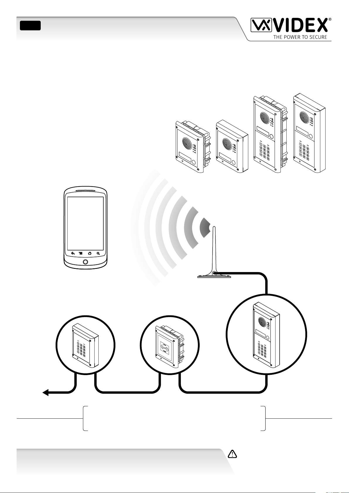
SYSTEM INTRODUCTION
The system is designed to work on the same technology as mobile phones. It enables a call to be made from an entry point (door,
gate etc), to any telephone number (mobile or land line). Up to 50 call buttons can be connected to the door panel, each able to
call four telephone numbers (if the rst is busy or not answered, the call can be diverted to up to three dierent numbers). The
standard GSM PRO intercom works on a 2G network. A 3G variant is also available (sux /3G to the part number e.g. Art.4810-0/3G,
Art.4810-1/3G etc.). Features of the system include:
• A dry contact relay output and push to exit input;
• Two open collector auxiliary outputs and two auxiliary inputs;
• Integrated Proximity Access Control (up to 1000 proximity fobs or cards can be stored, these fobs/cards when presented to
the nameplate window on the GSM PRO intercom or directly in front of the Art.4850R expansion reader will activate the
door/gate relay);
• Call progress speech annunciation and call progress LED indication;
• Dial to Open facility (this feature enables up to 1000 stored numbers to dial the GSM PRO intercom, the intercom panel will
not answer these calls, but will activate the door/gate relay without being charged for the call);
• Programmable call button timeband facility (a single timeband only);
• Programmable access control timeband facility (up to 10 timebands);
• Programmable free access timeband facility (up to 10 timebands);
• Up to 10 programmable access levels;
• Micro USB connection for ease of programming using the GSMSK PC software (version 4.0.0.0 or later);
• RS485 bus terminals for connecting additional ‘slave’ devices including coded keypads (Art.4903) and additional proximity
readers (Art.4850R), up to a maximum of 8 devices, also used for ease of programming using the GSMSK PC software;
• Integrated bootloader function for updating intercom panel rmware via the GSMSK PC software;
• Event logging system that can record up to 4000 events which can be downloaded via the GSMSK PC software;
• Remote event logging facility (unlimited events) which can be monitored in real time (also refer to additional notes on page
71 under user management).
Programming of the telephone numbers (primary no, divert no’s and dial to open no’s) and the additional features including
programming key fobs for the integrated proximity reader and additional proximity readers, programming access codes for
additional coded keypads, timebands, access levels etc. can be carried out via text messaging (refer to notes programming the
GSM intercom on pages 37 - 61) or using the GSMSK PC software (refer to the manual GSMSK_66251720_EN_V2-0 or later).
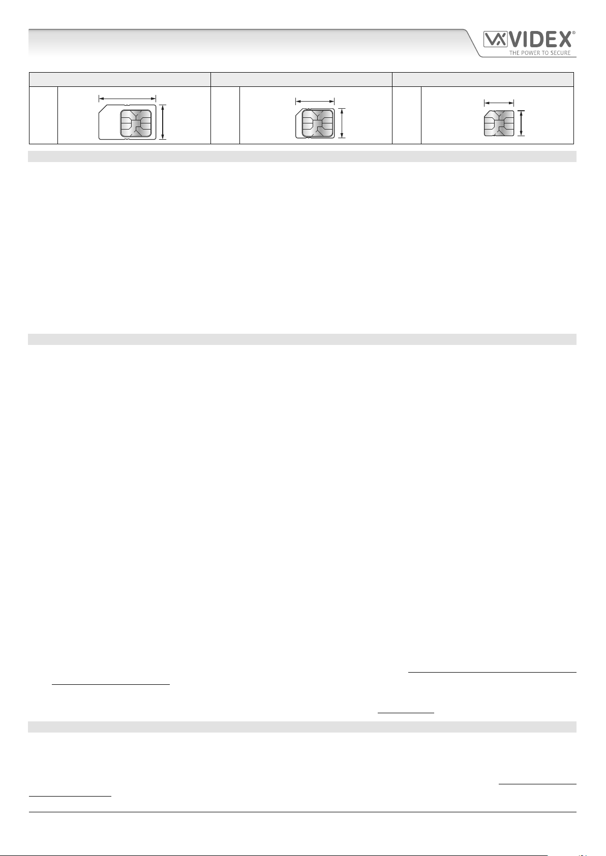
SIM CARD SELECTION
A SIM card is required for this product but not supplied by Videx. The GSM PRO intercom can only accept a standard size SIM card
(refer to the following SIM card size chart), both a micro-SIM and nano-SIM are not suitable. It is recommended to choose the SIM
card which has the best coverage for the area in which the intercom panel will be installed. Both contract and ‘Pay as you go’ SIM
cards can be used, however if using a ‘Pay as you go’ we would recommend setting up an automatic top up to avoid running short
on credit and losing the use of the intercom panel. Alternatively if you already have a contract mobile phone it should be possible
to get a second SIM card and telephone number on the existing account. For more information contact the SIM card provider or
visit their website.
4000 Series GSM Audio Intercom - Technical Manual
- 4 -
66250754-EN - V1.0 - 18/02/19
4000 Series GSM Audio Intercom with Proximity
Introduction
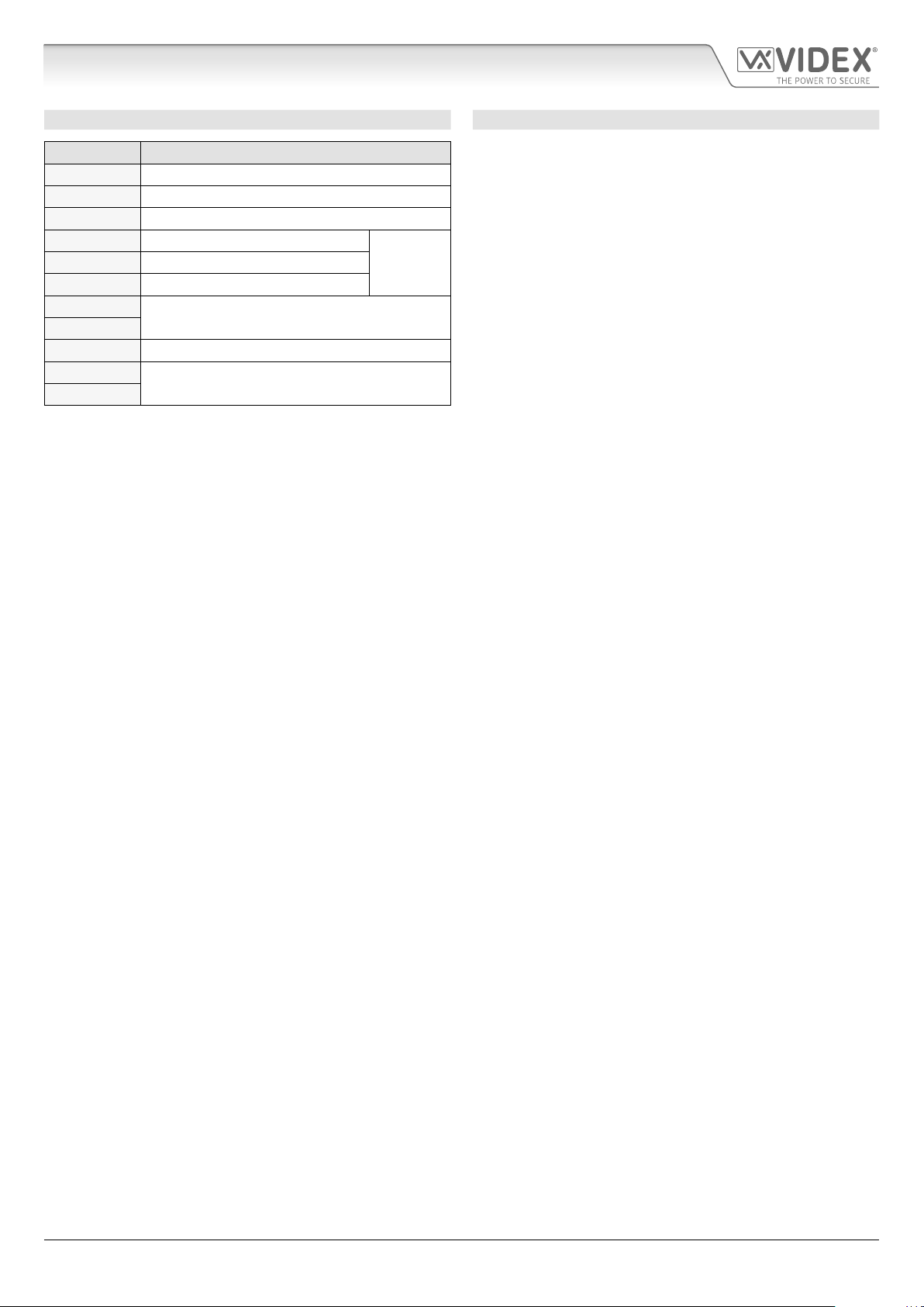
Standard SIM Micro-SIM Nano-SIM
25mm
15mm
15mm
12mm
12.3mm
8.8mm
NETWORK PROVIDER SELECTION
It is imperative that for the reliable operation of the system that the best network provider for the area is selected. Problems such as
network disconnection can occur if the provider has signal or interference problems for that area. We would recommend using a GSM
signal strength meter to survey the intended antenna location. Contact Videx for more information on where to purchase a tester.
For UK customers, as an initial check we also recommend visiting the ofcom website www.ofcom.org.uk and follow the onsite links to
their online mobile coverage tool (ofcom broadband and mobile checker app). This tool will advise on the best coverage for the main
network providers and other general queries that you may have about the service provider. For all overseas customers we suggest
consulting the website of the network provider that will be used to check the coverage in your area.
The antenna should always be mounted vertically at the highest point possible. Metal structures and sources of interference such as
power cables, control panels etc. can aect signals and so the antenna should be mounted away from these.
When registering a new SIM you may be asked for the IMEI number. This is the unique serial number of the GSM intercom. This
number is located internally on the main hardware chip inside the GSM PRO module. To obtain the IMEI number from the GSM
module refer to the programming notes obtain the GSM’s IMEI number on page 61.
PRECAUTIONARY ADVICE
• When mounting the GSM antenna, choose a location which is away from human interaction and away from the intercom panel.
Route the GSM antenna cable from the intercom panel so that it is separate from the power supply cables and microphone wire.
• Always ensure the power is switched OFF to the intercom panel before inserting or removing the SIM card.
• New SIM cards will need registering with the network service provider before they can be used. Full details of how this is done
can normally be found in the SIM card pack. It will normally require that the SIM card is inserted into a mobile phone, a number
dialled and instructions followed. While the SIM is in the mobile phone it would be a good time to disable any PIN codes, call
diverts, ring back and disable features such as voicemail and text alerts. Details of how to do this can be found on the SIM card
provider’s web site or by calling their customer services. Recommended SIM card providers are: Vodafone, T-Mobile, O2 or
Orange/EE. The 3 network can only be used on our 3G devices (Art.4810-0/3G, Art.4810-1/3G etc.), also refer to page 6.
• To be able to receive text messages from the intercom panel, the SIM card will require an SMS service centre number. This is
normally preinstalled on new SIM cards but if you are having trouble receiving SMS messages you will need to conrm this by
inserting the SIM card into a mobile phone and using the phones menu options to check it. If a number is not programmed then
it should be programmed while in the phone (the number can be obtained from the network service provider).
• Voicemail and text alerts must be switched OFF on the SIM card when using the dial in to release the door/gate feature. For
Vodafone and O2 this can be done while the SIM card is in the intercom panel. For Orange/EE, T-Mobile and other providers the
SIM card must be removed from the intercom panel, inserted into a mobile phone and the mobile phone menu instructions
followed. This procedure may vary from provider to provider of dierent countires, we suggest contacting your provider for
information.
• When storing the intercom panel’s telephone number in your own mobile phone avoid using an obvious name such as ‘Front
Door’, or ‘My Gate’ as this would make it easy to decipher if your phone was lost or stolen.
• The PIN request feature must be disabled on the SIM card before using it in the Intercom panel. It is likely on a new SIM card that
it will not be enabled but if it is, it will prevent the system from working at all.
• This product may not be suitable for installation in hospitals, health care facilities or in the presence of ammable gases or
liquids. Seek advice and authorisation before installing this product in these locations. This product is not designed to be used
as an emergency call point.
Network provider and services conguration codes mentioned in this manual are specic for the UK. For overseas customers please contact
the network provider of your country for the corresponding codes, however Videx oers no guarantee that any additional codes will work.
IMPORTANT NOTE ABOUT THE SIM
When using a pay monthly SIM card you can ask the service provider to put a spend limit (credit limit) on the account (Vodafone
call this service ‘spend checker’). This is to safeguard against possible problems which could result in a large phone bill at the end
of the month. Most network providers oer this service. You will need to either ring or e-mail them to set this up. Automatic top
ups should also have a monthly limit. We would suggest a limit of £50.00 which should be more than enough. This service is not
provided by Videx.
4000 Series GSM Audio Intercom - Technical Manual
- 5 -
66250754-EN - V1.0 - 18/02/19
4000 Series GSM Audio Intercom with Proximity
System Components and Available Versions
DESCRIPTION
A system comprises of an intercom panel, power supply, SIM card (SIM card not provided by Videx) and antenna. The intercom panel
is part of the Videx 4000 series modular design allowing it to be customised to the installation requirements for example including
coded access, proximity access or including the correct number of call buttons (up to 50 call buttons).
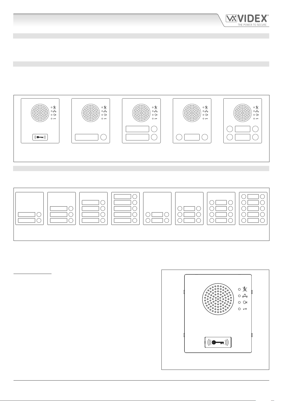
ART. 4810 GSM PRO INTERCOM AVAILABLE VERSIONS
The intercom panel can include any of the modules from the 4000 series range and uses the standard 4000 series surface and
ush mounting frames. The GSM PRO module is however essential and includes all the GSM communication electronics, SIM card
(supplied separately) and connections. The intercom module is available in a 0 button, 1 button, 2 button and 4 button conguration
(with all onboard buttons internally wired), as shown in Fig.1 along with their part numbers.
2
24
1 1 13 13
Art. 4810-0,
Art. 4810-0/3G
Fig. 1
Art. 4810-1
Art. 4810-1/3G
Art. 4810-2
Art. 4810-2/3G
Art. 4810-1D
Art. 4810-1D/3G
Art. 4810-2D
Art. 4810-2D/3G
EXTENSION BUTTON MODULES
The GSM intercom module will accept up to 50 call buttons. Any of the standard 4000 series button modules can be used as shown
in Fig.2 along with their part numbers. Please note that button 1 is in the bottom right corner of the module counting up.
10
9
8
7
6
Art. 4842 Art. 4843 Art. 4844 Art. 4845 Art. 4842D Art. 4843D Art. 4844D Art. 4845D
Fig. 2
5
4
3
2
1
Button connections to the GSM module are shown in Fig.4 on page 7 (only the wiring of the button matrix is shown). It is important
to take care when using additional button modules with a GSM intercom module which also has onboard buttons. For example, an
intercom module with one button means the extension button module used must start wiring from button 2, an intercom module
with 2 buttons means the extension button module used must start wiring from button 3 and so on.
IMPORTANT NOTE: When extension button modules are being used
on systems where proximity access is required and the Art.4810-0 GSM
PRO module is used, the location of the onboard proximity reader is on
the front of the main GSM PRO module below the speaker, as shown in
Fig.3.
Standard versions of the GSM PRO (e.g. Art.4810-0 etc.) works on a 2G
network. A 3G variant is also available (see Fig.1 above) that works on a
3G network, sux /3G to the part no. (e.g. Art.4810-1/3G etc.).
4000 Series GSM Audio Intercom - Technical Manual
- 6 -
Art. 4810-0, Art.4810-0/3G
Fig. 3
66250754-EN - V1.0 - 18/02/19
4000 Series GSM Audio Intercom with Proximity
System Components and Available Versions
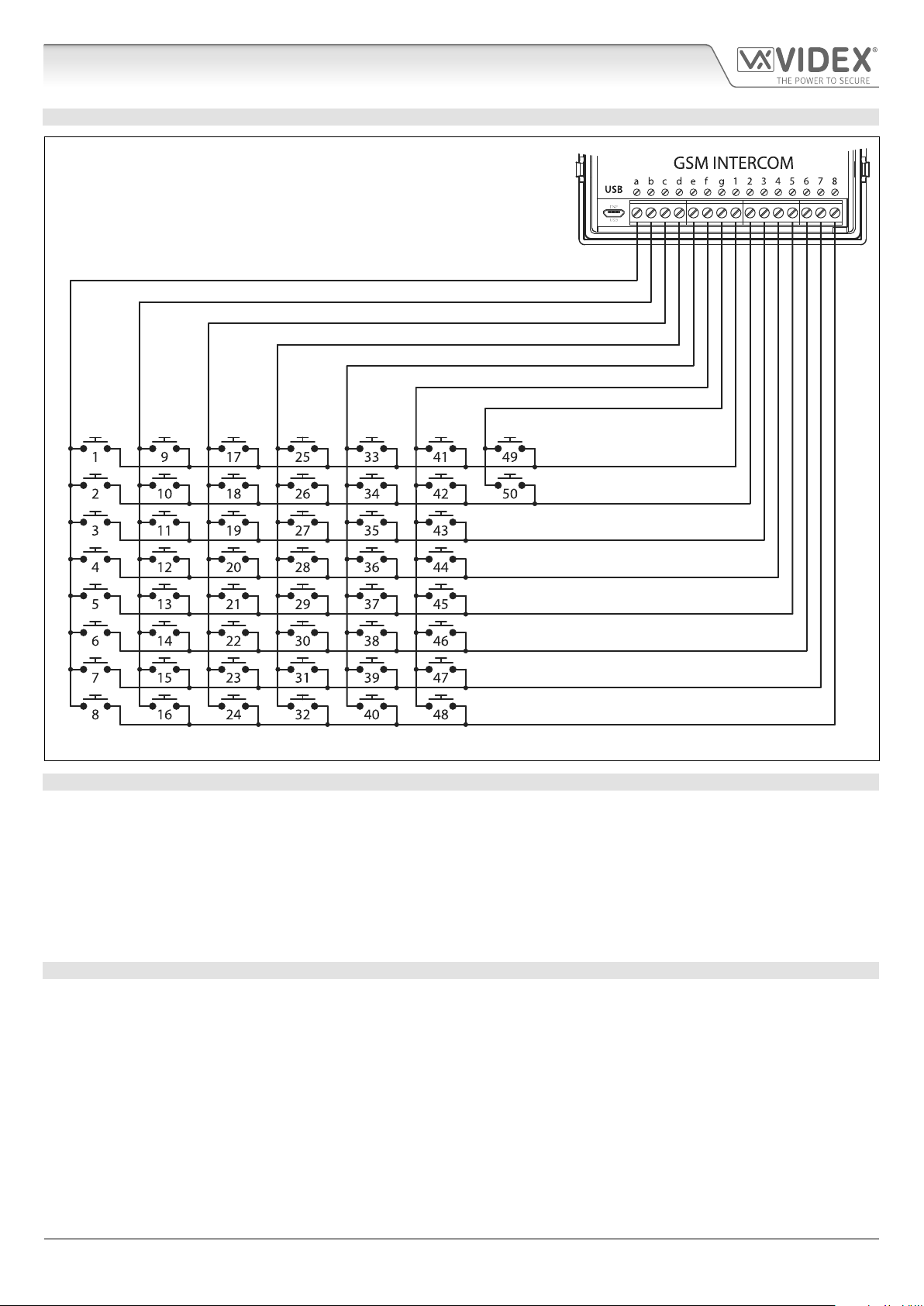
BUTTON MATRIX WIRING
Fig. 4
BUTTON MODULE NOTES
If the GSM module has 1 button (Art.4810-1), the additional button module buttons should be wired starting from button number
2 (i.e. the rst button of the button module should be connected between a & 2, the next between a & 3 etc.).
If the GSM module has 2 buttons (Art.4810-2), the additional button module buttons should be wired starting from button number
3 (i.e. the rst button of the button module should be connected between a & 3, the next between a & 4 etc.).
If the GSM module has 4 buttons (Art.4810-2D), the additional button module buttons should be wired starting from button number
5 (i.e. the rst button of the button module should be connected between a & 5, the next between a & 6 etc.).
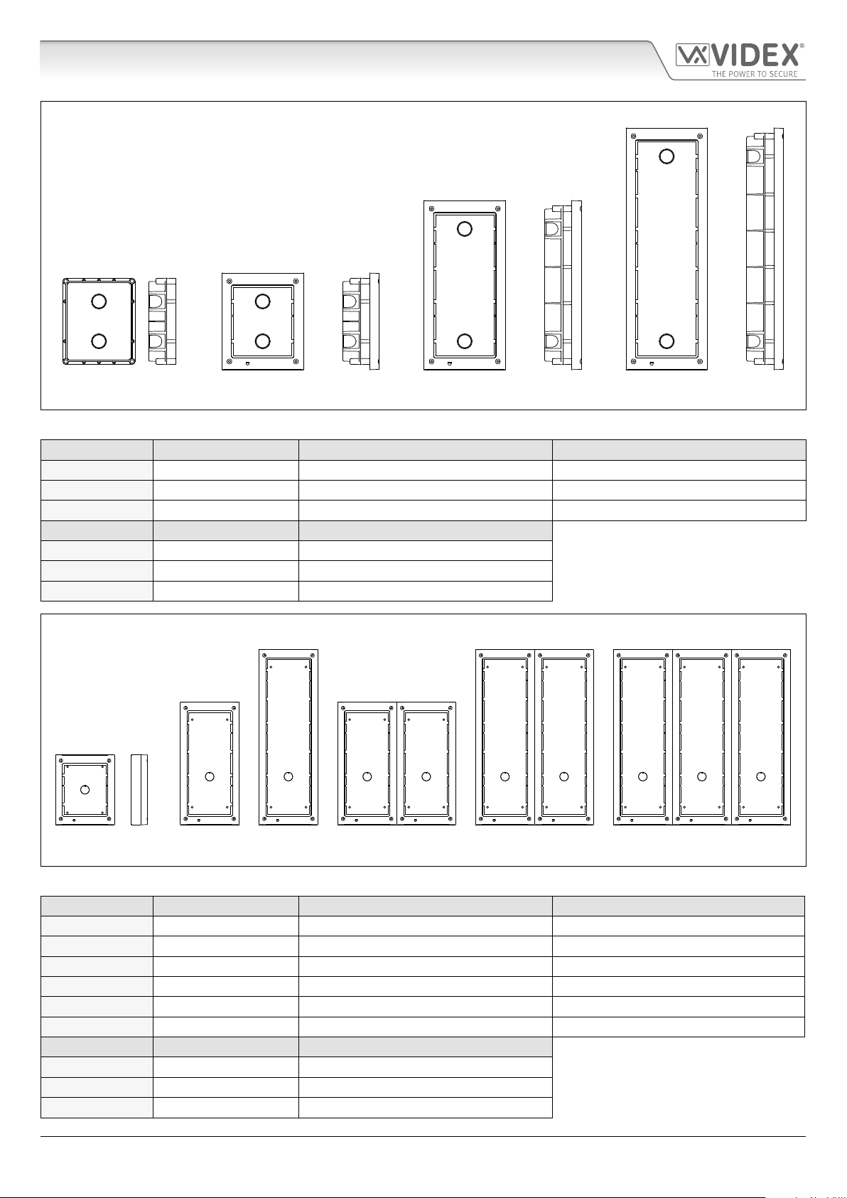
4000 SERIES BACK BOXES AND MOUNTING FRAMES
Both surface and ush back boxes and mounting frames are available. The size of the frame will depend on the number of modules
that make up the GSM4K/GSM4KCR kit. The last digit of the frame code indicates the number of modules it will take. Frames are
available in gun metal gray nish. The 4000 series mounting frames available are shown in Fig.5 (ush) and Fig.6 (surface) with the
following tables showing the back box dimensions including the part numbers and dimensions for optional ush and surface 4000
series rainshields.
4000 Series GSM Audio Intercom - Technical Manual
- 7 -
66250754-EN - V1.0 - 18/02/19
4000 Series GSM Audio Intercom with Proximity
System Components and Available Versions
Flush Back Boxes and Mounting Frames
Art. 4851 Art. 4852 Art. 4853
Fig. 5
Flush Back Box Dimensions (inc. optional ush rainshields)
Part No. Housed Modules Front Frame (W x H x D) mm Back Box (W x H x D) mm
Art.4851 1 135 x 160 x 15.7 120 x 143 x 46
Art.4852 2 135 x 280.2 x 15.7 120 x 263.2 x 46
Art.4853 3 135 x 400.4 x 15.7 120 x 383.4 x 46
Part No. Module Size Rainshield Dimensions (W x H x D) mm
Art.4871 1 140 x 163 x 35
Art.4872 2 140 x 283 x 35
Art.4873 3 140 x 403 x 35
Surface Back Boxes and Mounting Frames
Art. 4881 Art. 4882 Art. 4883 Art. 4884 Art. 4886 Art. 4889
Fig. 6
Surface Back Box Dimensions (inc. optional surface rainshields)
Part No. Housed Modules No. of Columns Back Box (W x H x D) mm
Art.4881 1 1 135 x 160 x 43
Art.4882 2 1 135 x 280.2 x 43
Art.4883 3 1 135 x 400.4 x 43
Art.4884 4 2 270 x 280.2 x 43
Art.4886 6 2 270 x 400.4 x 43
Art.4889 9 3 405 x 400.4 x 43
Part No. Module Size Rainshield Dimensions (W x H x D) mm
Art.4891 1 140 x 163 x 62
Art.4892 2 140 x 283 x 62
Art.4893 3 140 x 403 x 62
4000 Series GSM Audio Intercom - Technical Manual
- 8 -
66250754-EN - V1.0 - 18/02/19
4000 Series GSM Audio Intercom with Proximity
7
System Components and Available Versions
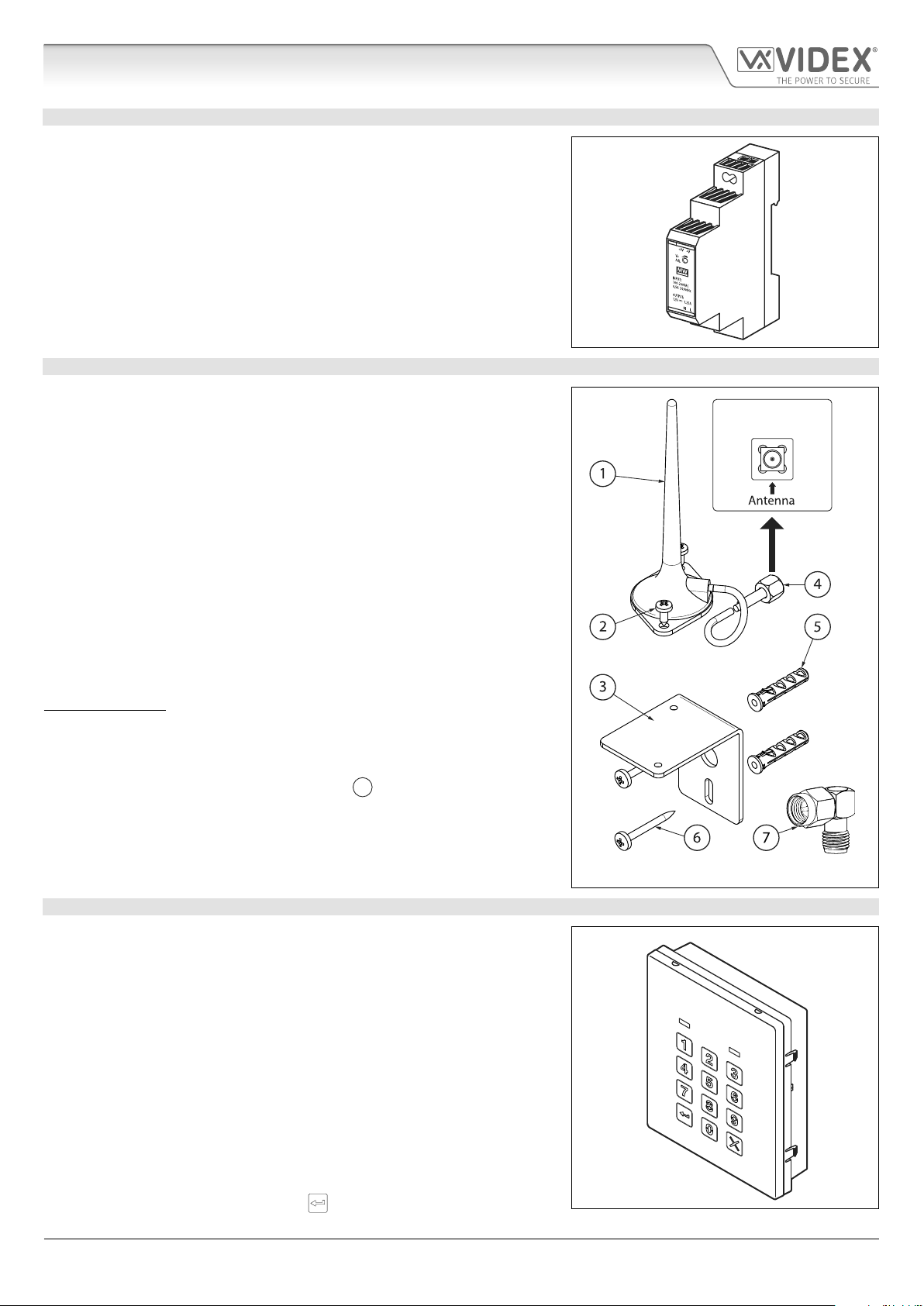
12VDC 2A POWER SUPPLY HDR1512
The Art. 4810 GSM PRO intercom is designed to work with power supplies in
the range of 12Vdc and should be capable of supplying a constant current of
no less than 1A. Both the GSM4K and GSM4KCR kits are supplied with a slim line
HDR-15-12, 12Vdc 1.25A power supply (refer to Fig.7).
ART. 432 GSM ANTENNA
Fig. 7
The Art.432 GSM antenna connects to the SMA female bulkhead connection on the
rear of the Art.4810 GSM PRO module. A GSM antenna with an SMA male connector
should be used (refer to Fig.8).
Antenna Parts
1. GSM antenna with magnetic base.
2. Self-threading screw (Ø3.5mm x 9.5mm).
3. Aluminium L bracket for mounting.
4. SMA male connector (cable length 2.5m).
5. Expansion type wall plugs (Ø6mm).
6. Self-threading screw (Ø4mm x 30mm).
7. Right angled SMA adapter.
IMPORTANT NOTE: An antenna must always be tted for the GSM module to
work. Always route the GSM antenna cable away from the microphone wires
and the power supply wires to avoid interference on the speech channels.
In instances where there is a tight tting space for the SMA male connector on
the antenna cable the right angled SMA adapter
can be used to help reroute
the cable down the back side of the GSM module.
SMA female bulkhead
connection on rear of
Art.4810 GSM PRO module
ART. 4903 CODELOCK
The Art.4903 codelock module (included as part of the GSM4KCR kits), see Fig.9,
can be powered from 12-24V AC or DC and includes 2 dry contact relay outputs
and two switched 0V push to exit inputs which can be used to trigger relay 1 &
2. It also includes an RS485 bus connection which can be linked to the Art.4810
GSM module and networked with other Art.4903 codelocks and/or Art.4850R
proximity devices (up to 8 devices in total).
When connected to the GSM PRO via RS485 it can operate up to 400 permanent
access codes (000-399) which can be assigned to trigger relay 1 or 2 or both. The
permanent codes can also have access levels and timebands assigned to them.
It can also operate up to 32 temporary codes. These codes can be between 4 - 8
digits long and are stored on the GSM PRO intercom. An additional two codes
(1 per relay) can be programmed directly via the keypad and are stored in the
codelock and not the GSM PRO module.
The relay time can be 01 - 99 seconds or set for latching (00). When in latching
mode, enter the code followed by ‘ENTER’
4000 Series GSM Audio Intercom - Technical Manual
to latch and to unlatch the relay.
- 9 -
Fig. 8
Fig. 9
66250754-EN - V1.0 - 18/02/19
4000 Series GSM Audio Intercom with Proximity
System Components and Available Versions
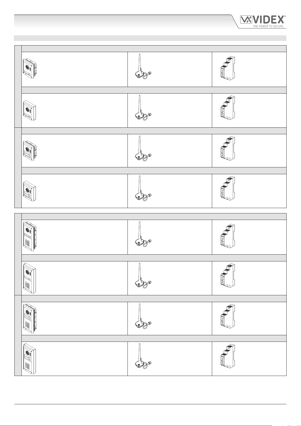
GSM INTERCOM AUDIO KITS
GSM4K-1 - ush mounting
1 Outdoor station composed of:
1 Art.4810-1: 1 button GSM (pro) unit
1 Art.4851: Flush mounting box
GSM4K-1S - surface mounting
1 Outdoor station composed of:
ONE WAY VERSIONS
GSM4K-2 - ush mounting
1 Art.4810-1: 1 button GSM (pro) unit
1 Art.4881: Surface mounting box
1 Outdoor station composed of:
1 Art.4810-2: 2 button GSM (pro) unit
1 Art.4851: Flush mounting box
1 GSM antenna
Art.432
1 GSM antenna
Art.432
1 GSM antenna
Art.432
1 Power supply
HDR-15-12
12Vdc 1.25A
1 Power supply
HDR-15-12
12Vdc 1.25A
1 Power supply
HDR-15-12
12Vdc 1.25A
GSM4K-2S - surface mounting
1 Outdoor station composed of:
1 Art.4810-2: 2 button GSM (pro) unit
TWO WAY VERSIONS
GSM4KCR-1 - ush mounting
GSM4KCR-1S - surface mounting
ONE WAY VERSIONS
GSM4KCR-2 - ush mounting
1 Art.4881: Surface mounting box
1 Outdoor station composed of:
1 Art.4810-1: 1 button GSM (pro) unit
1 Art.4903: 4000 series codelock
1 Art.4852: Flush mounting box
1 Outdoor station composed of:
1 Art. 4810-1: 1 button GSM (pro) unit
1 Art.4903: 4000 series codelock
1 Art.4882: Surface mounting box
1 Outdoor station composed of:
1 Art.4810-2: 2 button GSM (pro) unit
1 Art.4903: 4000 series codelock
1 Art.4852: Flush mounting box
1 GSM antenna
Art.432
1 GSM antenna
Art.432
1 GSM antenna
Art.432
1 GSM antenna
Art.432
1 Power supply
HDR-15-12
12Vdc 1.25A
1 Power supply
HDR-15-12
12Vdc 1.25A
1 Power supply
HDR-15-12
12Vdc 1.25A
1 Power supply
HDR-15-12
12Vdc 1.25A
GSM4KCR-2S - surface mounting
1 Outdoor station composed of:
1 Art.4810-2: 2 button GSM (pro) unit
TWO WAY VERSIONS
4000 Series GSM Audio Intercom - Technical Manual
1 Art.4903: 4000 series codelock
1 Art.4882: Surface mounting box
- 10 -
1 GSM antenna
Art.432
1 Power supply
HDR-15-12
12Vdc 1.25A
66250754-EN - V1.0 - 18/02/19
4000 Series GSM Audio Intercom with Proximity
System Components and Available Versions
GSM4K AUDIO KITS
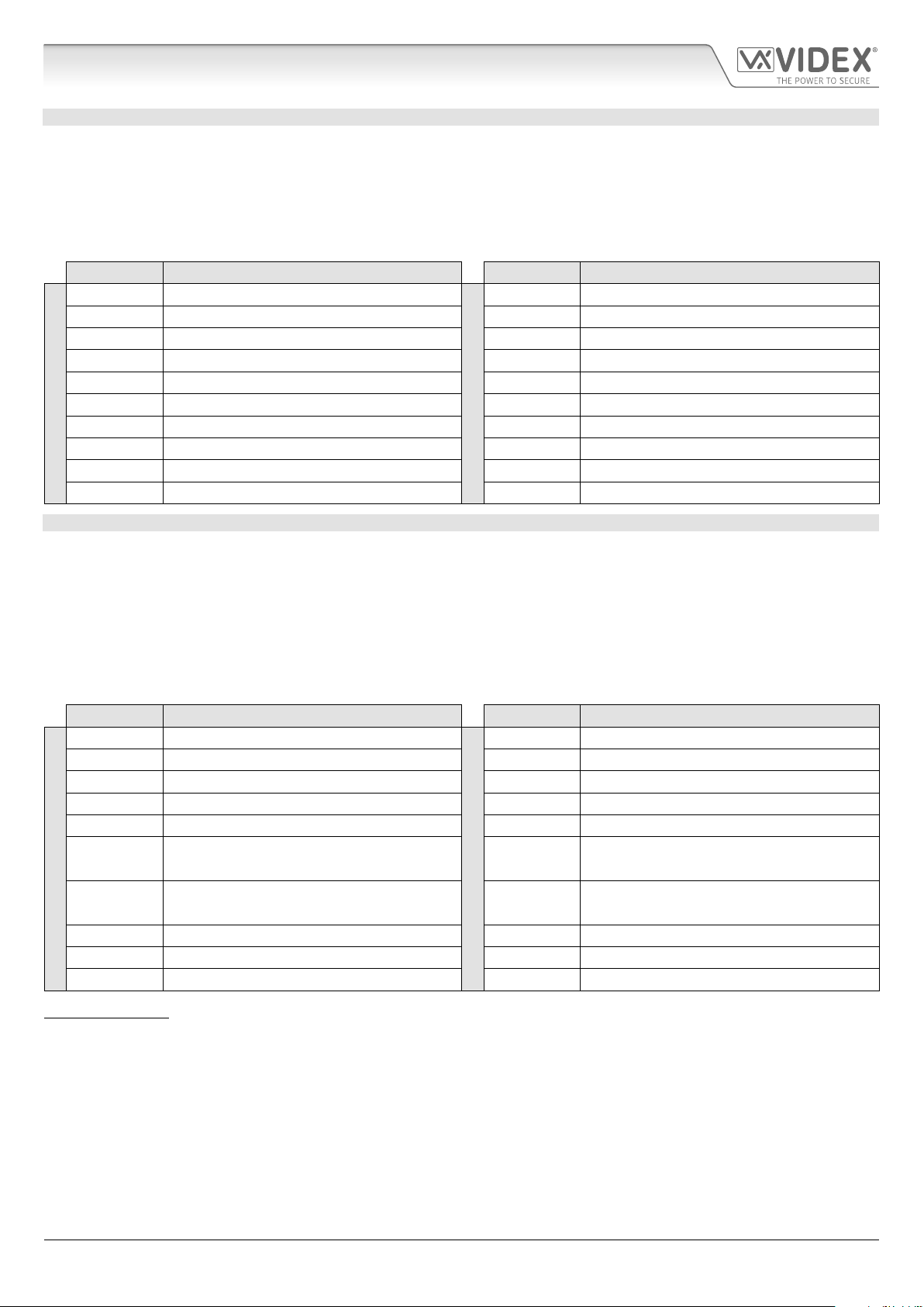
Additional GSM4K-n (ush) kit versions are available from 3 way kits up to 12 way kits: GSM4K-3 up to GSM4K-12. Each audio
kit comes with the appropriate Art.4810 GSM module, appropriate extension button module(s) and appropriate ush back box
depending on the GSM4K-n kit required (where n = the number of call buttons), refer to table below.
Additional GSM4K-nS (surface) kit versions are available from 3 way kits up to 12 way kits: GSM4K-3S to GSM4K-12S. Each audio
kit comes with the appropriate Art.4810 GSM module, appropriate extension button module(s) and appropriate surface back box
depending on the GSM4K-nS kit required (where n = the number of call buttons), refer to table below.
Kit No. Outdoor station composed of: Kit No. Outdoor station composed of:
GSM4K-3 1 Art.4810-0; 1 Art.4843; 1 Art.4852
GSM4K-4 1 Art.4810-0; 1 Art.4844; 1 Art.4852 GSM4K-4S 1 Art.4810-0; 1 Art.4844; 1 Art.4882
GSM4K-5 1 Art.4810-0; 1 Art.4845; 1 Art.4852 GSM4K-5S 1 Art.4810-0; 1 Art.4845; 1 Art.4882
GSM4K-6 1 Art.4810-1; 1 Art.4845; 1 Art.4852 GSM4K-6S 1 Art.4810-1; 1 Art.4845; 1 Art.4882
GSM4K-7 1 Art.4810-2; 1 Art.4845; 1 Art.4852 GSM4K-7S 1 Art.4810-2; 1 Art.4845; 1 Art.4882
GSM4K-8 1 Art.4810-0; 1 Art.4843; 1 Art.4845; 1 Art.4853 GSM4K-8S 1 Art.4810-0; 1 Art.4843; 1 Art.4845; 1 Art.4883
FLUSH
GSM4K-9 1 Art.4810-0; 1 Art.4844; 1 Art.4845; 1 Art.4853 GSM4K-9S 1 Art.4810-0; 1 Art.4844; 1 Art.4845; 1 Art.4883
GSM4K-10 1 Art.4810-0; 2 Art.4845; 1 Art.4853 GSM4K-10S 1 Art.4810-0; 2 Art.4845; 1 Art.4883
GSM4K-11 1 Art.4810-1; 2 Art.4845; 1 Art.4853 GSM4K-11S 1 Art.4810-1; 2 Art.4845; 1 Art.4883
GSM4K-12 1 Art.4810-2; 2 Art.4845; 1 Art.4853 GSM4K-12S 1 Art.4810-2; 2 Art.4845; 1 Art.4883
GSM4K-3S 1 Art.4810-0; 1 Art.4843; 1 Art.4882
SURFACE
GSM4KCR AUDIO KITS
Additional GSM4KCR-n (ush) kit versions are available from 3 way kits up to 12 way kits: GSM4KCR-3 up to GSM4KCR-12. Each
audio kit comes with the appropriate Art.4810 GSM module, appropriate extension button module(s), Art.4903 codelock module
and appropriate ush back box depending on the GSM4KCR-n kit required (where n = the number of call buttons), refer to table
below.
Additional GSM4KCR-nS (surface) kit versions are available from 3 way kits up to 12 way kits: GSM4KCR-3S to GSM4KCR-12S. Each
audio kit comes with the appropriate Art.4810 GSM module, appropriate extension button module(s), Art.4903 codelock module
and appropriate surface back box depending on the GSM4KCR-nS kit required (where n = the number of call buttons), refer to table
below.
Kit No. Outdoor station composed of: Kit No. Outdoor station composed of:
GSM4KCR-3 1 Art.4810-0; 1 Art.4843; 1 Art.4903; 1 Art.4853
GSM4KCR-4 1 Art.4810-0; 1 Art.4844; 1 Art.4903; 1 Art.4853 GSM4KCR-4S 1 Art.4810-0; 1 Art.4844; 1 Art.4903; 1 Art.4883
GSM4KCR-5 1 Art.4810-0; 1 Art.4845; 1 Art.4903; 1 Art.4853 GSM4KCR-5S 1 Art.4810-0; 1 Art.4845; 1 Art.4903; 1 Art.4883
GSM4KCR-6 1 Art.4810-1; 1 Art.4845; 1 Art.4903; 1 Art.4853 GSM4KCR-6S 1 Art.4810-1; 1 Art.4845; 1 Art.4903; 1 Art.4883
GSM4KCR-7 1 Art.4810-2; 1 Art.4845; 1 Art.4903; 1 Art.4853 GSM4KCR-7S 1 Art.4810-2; 1 Art.4845; 1 Art.4903; 1 Art.4883
GSM4KCR-8
FLUSH
GSM4KCR-9
GSM4KCR-10 1 Art.4810-0; 2 Art.4845; 1 Art.4903; 2 Art.4852 GSM4KCR-10S 1 Art.4810-0; 2 Art.4845; 1 Art.4903; 1 Art.4884
GSM4KCR-11 1 Art.4810-1; 2 Art.4845; 1 Art.4903; 2 Art.4852 GSM4KCR-11S 1 Art.4810-1; 2 Art.4845; 1 Art.4903; 1 Art.4884
GSM4KCR-12 1 Art.4810-2; 2 Art.4845; 1 Art.4903; 2 Art.4852 GSM4KCR-12S 1 Art.4810-2; 2 Art.4845; 1 Art.4903; 1 Art.4884
1 Art.4810-0; 1 Art.4843; 1 Art.4845;
1 Art.4903; 2 Art.4852
1 Art.4810-0; 1 Art.4844; 1 Art.4845;
1 Art.4903; 2 Art.4852
GSM4KCR-3S 1 Art.4810-0; 1 Art.4843; 1 Art.4903; 1 Art.4883
GSM4KCR-8S
SURFACE
GSM4KCR-9S
1 Art.4810-0; 1 Art.4843; 1 Art.4845;
1 Art.4903; 1 Art.4884
1 Art.4810-0; 1 Art.4844; 1 Art.4845;
1 Art.4903; 1 Art.4884
IMPORTANT NOTE: The GSM audio kits listed above work on a 2G network. For the 3G variant remember to sux the kit part
no. with /3G, e.g. GSM4K-4/3G, GSM4KCR-6S/3G etc.
All GSM audio kits are supplied with a HDR-15-12 12Vdc, 1.25A slim line power supply.
4000 Series GSM Audio Intercom - Technical Manual
- 11 -
66250754-EN - V1.0 - 18/02/19
4000 Series GSM Audio Intercom with Proximity
Art. 4810 Technical Information
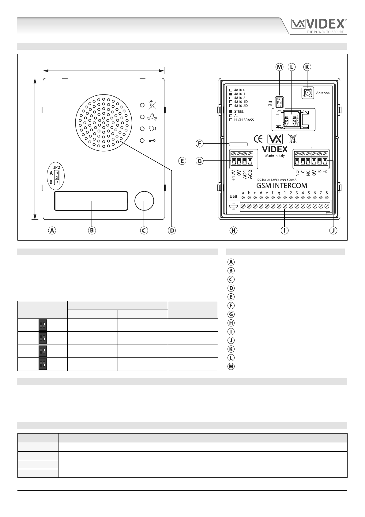
ART. 4810 GSM PRO MODULE
103mm
120mm
Internal jumper JP2
Nameplate LED illumination adjustment
R02A
GSM4K-3.0.2
RS485
Fig. 10
SPEAKER VOLUME ADJUSTMENT DIPSWITCH SETTINGS LEGEND
There are 2 dip-switches located on the back of the GSM module next to the
antenna connection, see Fig.10. They can be used to adjust the volume from
the door intercom speaker (see table below). Additionally, the volume can also
be adjusted during a call electronically via the telephone keypad (refer to user
command table on page 66).
Internal nameplate LED jumper (JP2)
Nameplate and proximity access reader
Call button
Intercom speaker
Call progress LED's
Dip-Switch
ON
1 2
ON
1 2
ON
1 2
ON
1 2
Dip-Switch Status
Dip No.1 Dip No.2
Gain (dB)
ON ON 6
ON OFF 12
OFF ON 18
OFF OFF 23.5
Current rmware version (GSM4K X.X.X)
Power input and auxiliary terminals
Micro USB connection
Button matrix terminals
Relay output and RS485 bus terminals
Antenna connection
SIM card holder
Speaker volume dip-switches
NAMEPLATE ILLUMINATION JUMPER JP2
The nameplate LED illumination jumper JP2 is located behind the GSM module’s front facia, as shown in Fig.10. To access the
jumper the facia must be removed and the jumper can be adjust as required. When JP2 is set in position A (upper 2 pins) the LED
is set for bright illumination, when JP2 is set in position B (lower 2 pins) the LED is set for low illumination and if JP2 is completely
removed this will disable the nameplate LED’s.
TERMINAL CONNECTIONS
Terminal Description
+12V 12 - 24Vdc or ac power.
0V 0V ground power.
AO1 Auxiliary output 1 (open collector, 150mA max.).
AO2 Auxiliary output 2 (open collector, 150mA max.).
4000 Series GSM Audio Intercom - Technical Manual
- 12 -
66250754-EN - V1.0 - 18/02/19
4000 Series GSM Audio Intercom with Proximity
Art. 4810 Technical Information
terminals continued...
NO Normally open relay contact.
C Common relay contact.
NC Normally closed relay contact.
0V
B
A
a - g
RS485 bus terminals for permanent connection to a PC, also used to network with Art.4903 codelock and Art.4850R
proximity reader (up to 8 devices max.).
Button matrix for connecting up to 50 call buttons, PTE, and auxiliary inputs.
The PTE (push to exit button) connects across g-6.
1 - 8
Auxiliary 1 input connects across g-5 (activates AO1 when set to mode 01).
Auxiliary 2 input connects across g-4 (sends SMS message to master telephone number).
JP2 Nameplate window LED illumination adjustment. JP2 position A = LED bright,
JP2 position B = LED low, JP2 removed = LED disabled.
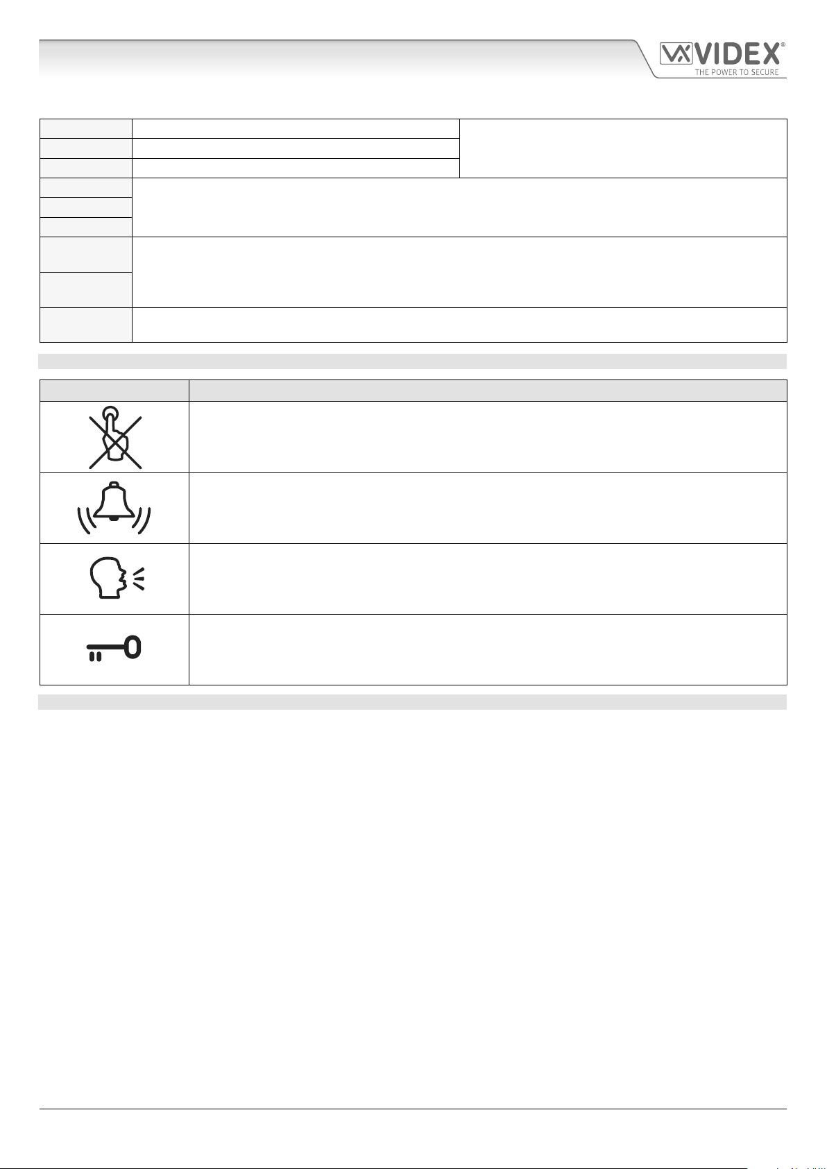
CALL PROGRESS LED’S
LED (sign) Description
The busy LED when illuminated, indicates that it is not possible to make a call because a call or a
conversation is in progress. The LED will be OFF when the system is in standby. If there is power on
the GSM intercom and the Art.432 antenna is not connected this LED will ash continuously until the
antenna is connected. The LED will ash while connecting to a network.
The call LED when illuminated, indicates that the call from the GSM intercom panel is in progress. The
LED will switch OFF when the call is answered or after the call time expires.
Relay contacts:
3A@24Vdc
3A@120Vac
The speak LED when illuminated, indicates that it is possible to speak because the call has been
answered. The LED will switch OFF at the end of a conversation when the telephone/mobile that has
been dialled hangs up or at the end of the call time.
The open LED when illuminated, indicates that the door lock (GSM relay) has been operated. It will
switch OFF at the end of the programmed “door opening” time. The LED will also illuminate and operate
the relay if a programmed key fob is presented to the onboard proximity reader (nameplate window).
TECHNICAL SPECIFICATION
Working Voltage: : 12 - 24Vdc or ac +/- 10%
Standby Current: : approx. 60mA
Max. Current: approx. 500mA (max.)
Call Buttons: up to 50 (max.)
Telephone Numbers per Button: 4 telephone numbers (1 primary, 3 diverts)
Dial to Open Numbers: up to 1000 (max.)
Proximity Access (fobs/cards): up to 1000 users (max.)
Coded Access: up to 400 permanent codes and 32 temporary codes (when used with Art.4903 via RS485 bus)
Call Progress LED's: 4 (busy, call, speak and open)
Programming Method: SMS messaging or PC software
RS485 Bus Connection: A, B and 0V
Push to Exit Input: 1 (push-to-make across terminals g-6)
Auxiliary Inputs: 2 (AO1 = across terminals g-5, AO2 = across terminals g-4)
Auxiliary Outputs: 2 (open collector output, switched 0V, 150mA max.)
Dry Contact Relay: C, NO and NC, 3A @ 24Vdc, 3A @ 120Vac
Event Logging: up to 4000 events (unlimited when using remote logging facility)
USB Port: micro USB
Timebands: 1 call button timeband; 10 access control and 10 free access timebands
Working Temperature: -10 +50
o
C
4000 Series GSM Audio Intercom - Technical Manual
- 13 -
66250754-EN - V1.0 - 18/02/19
4000 Series GSM Audio Intercom with Proximity
Art. 4903 Technical Information
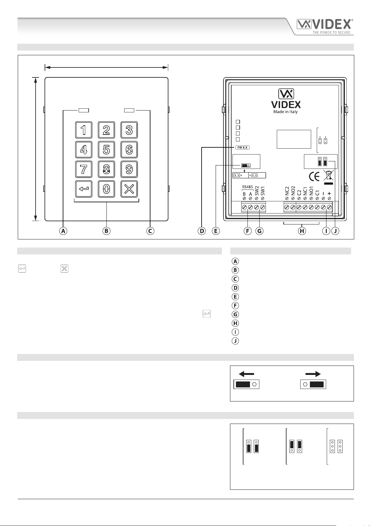
ART. 4903 CODELOCK MODULE
103mm
120mm
4903
STEEL
ALI
HIGH BRASS
MATTE
Note: Remove MOV
jumper completely
when using a relay to
trigger a gate controller.
MOV
NO2 NC2
NO1 NC1
RS485 BUS TERMINATION
Fig. 11
DESCRIPTION LEGEND
The module features 12 stainless steel buttons, backlit in blue (keys 0 - 9, ENTER
and CLEAR ), 2 LED’s (green LED = data, red LED = status indication)
for progress information during use and programming and a stainless steel or
aluminium front plate, see Fig.11. With two integral relays (RLY1 and RLY2) each
with common (C), normally open (NO) and normally closed (NC) connections
and two switched 0V push to exit inputs SW1 and SW2 to enable the external
triggering of the relays. Key presses are signalled acoustically while each button
press has a tactile feel. Entering the correct code followed by ENTER will
activate the relevant relay.
Data LED (green)
Backlit (blue) key buttons
Status indication LED (red)
Current rmware version (FW X.X)
RS485 bus termination jumper (JP1)
RS485 bus terminals
PTE terminals (SW1 and SW2)
Relay terminals (RLY1 and RLY2)
Power input terminals
Back EMF protection (JP2 and JP3)
OFFON
RS485 BUS TERMINATION JUMPER JP1
The jumper JP1 on the rear of the keypad sets the RS485 bus termination when
connected to the Art.4810 GSM PRO or other RS485 devices. By default the
jumper is set to the ON position (across to the left). When more than one RS485
device is connected to the keypad in line on the RS485 bus terminals then the
jumper can be set to the OFF position (across to the right) and only set to the
ON (closed) position on the end of line device, see Fig.12.
RELAY BUILTIN BACK EMF PROTECTION JP2 AND JP3
The Art.4903 includes selectable back EMF protection (metal oxide varistors)
jumpers JP2 and JP3 for each relay (marked MOV) and are used to select the
protection type. When using a fail secure lock with connections C & NO the
jumper should be in the NO position. When using a fail open (safe) lock with
connections C & NC the jumper should be in the NC position, as shown in
Fig.13. When using the codelock to trigger a gate controller or another third
party controller the jumper should be removed completely (this disables the
protection on the relay).
4000 Series GSM Audio Intercom - Technical Manual
- 14 -
ON OFF
Fig. 12
NC2
NC1
MOV
NO2
NO1
NO position for fail
secure lock release
Fig. 13
NC2
NC1
MOV
NO2
NO1
NC position for fail
safe lock release
66250754-EN - V1.0 - 18/02/19
NC2
MOV
NO2
remove jumpers
for gate controls
NC1
NO1
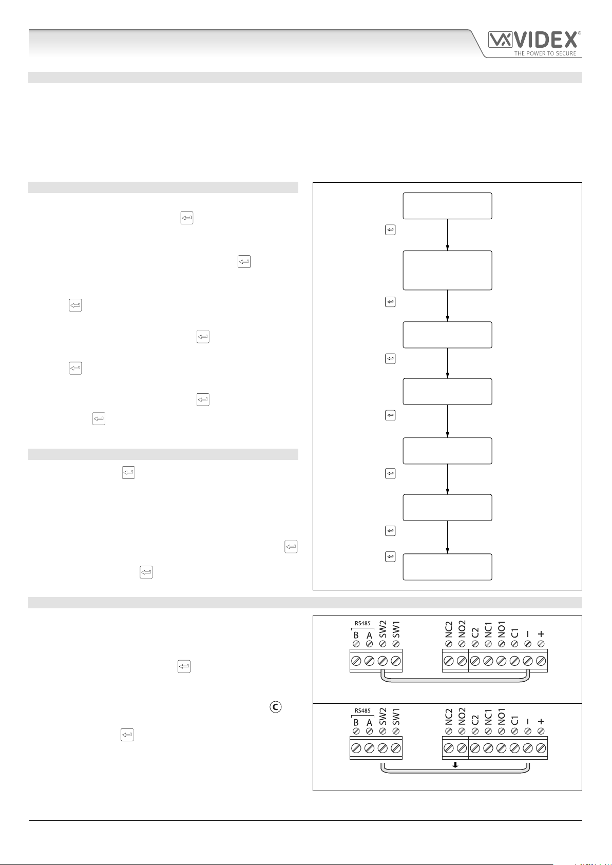
4000 Series GSM Audio Intercom with Proximity
ENTER THE
“ENGINEER’S CODE”
CONFIRM
OR CHANGE
“ENGINEER’S CODE”
ENTER
“ACCESS 1 CODE”
ENTER
“ACCESS 1 TIME”
ENTER
“ACCESS 2 CODE”
ENTER
“ACCESS 2 TIME”
SYSTEM
READY TO USE
Press ENTER
(red LED ON)
Press ENTER
(melody)
Press ENTER
(melody)
Press ENTER
(melody)
Press ENTER
(melody)
Press 1 six times
“111111”
(factory default)
Press 1 six times
“111111” again or
type new engineer’s
code (4 to 8 digits)
Type code to enable
relay 1 (4 to 8 digits)
Type code to enable
relay 2 (4 to 8 digits)
Two digits (01 to 99)
i.e. 05 = 5 seconds,
00 = latching
Two digits (01 to 99)
i.e. 05 = 5 seconds,
00 = latching
red LED OFF
Press ENTER
twice again to exit
(melody)
Press ENTER
(melody)
Art. 4903 Technical Information
PROGRAMMING AS A STANDALONE KEYPAD
When using the Art.4903 as a standalone keypad the programming is the same as the programming of an Art.4800M keypad
(refer to programming guide and owchart below). All programming is carried out using the keypad. The programming menu is
protected by an ENGINEER’S CODE, the factory default of which is six times 1 (“111111”). This code can be changed to any 4 to 8
digit ENGINEER’S CODE during the programming and is used to gain entry to the programming menu only.
Each relay (RLY1 and RLY2) can be programmed with a 4 - 8 digit access code (one code per relay) and will activate the respective
relay for the programmed relay time (01 - 99 seconds or 00 for latching). The access code programmed is stored in the keypads
internal memory.
PROGRAMMING GUIDE
• Enter the ENGINEER’S CODE: rst time type six times 1 (111111
factory default) and press ENTER
will illuminate);
• Conrm ENGINEER’S CODE: re-type the same code again or
type a new code (4 to 8 digits) then press ENTER
(melody);
• Enter the code (4 to 8 digits) to enable RELAY 1 then press
ENTER
to conrm, (melody);
• Enter the RELAY 1 operation time (2 digits 01 to 99, i.e. 05 = 5
seconds, 00 = latch) then press ENTER
to conrm, (the red LED
to conrm,
to conrm, (melody);
• Enter the code (4 to 8 digits) to enable RELAY 2 then press
ENTER
to conrm, (melody);
• Enter the RELAY 2 operation time (2 digits 01 to 99, i.e. 05 = 5
seconds, 00 = latch) then press ENTER
• Press ENTER
twice again to exit programming (melody);
to conrm, (melody);
• The system is ready to use (the red LED will switch OFF).
PROGRAMMING NOTES
• Pressing the ENTER
process, without changing any parameters, will exit from the
programming menu.
• When entering a relay code it must be dierent from the
ENGINEER'S CODE.
• To latch the relay type in the access code then press ENTER
to conrm. To unlatch the relay type in the same access code
again then press ENTER
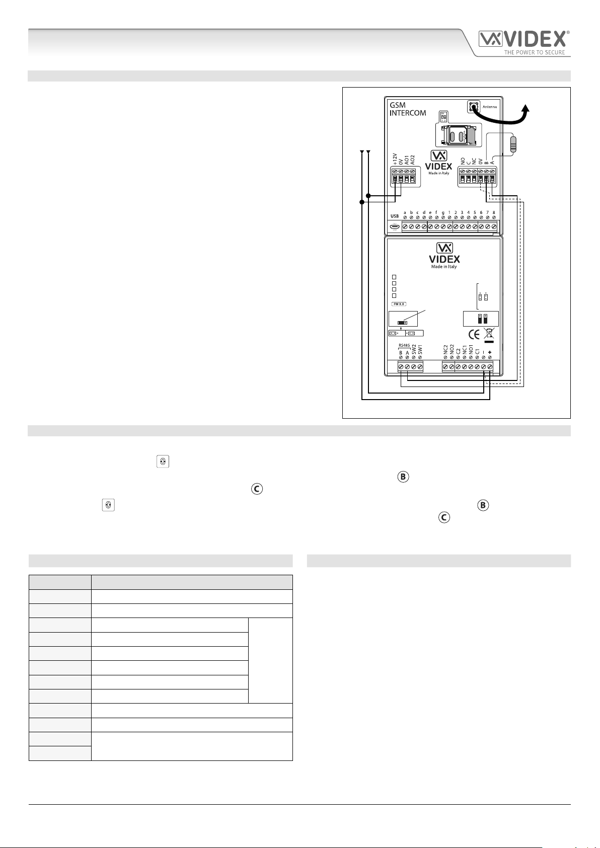
RESETTING THE CODELOCK BACK TO FACTORY DEFAULTS
Follow the steps below to reset the codelock to factory defaults:
1. Remove/disconnect the power from the Art.4903 codelock;
button twice during the programming
2. Short out terminals - and SW2, see Fig.14;
3. Press and hold down the ENTER
down while the power is switched back ON;
4. When power is restored to the codelock wait for the module
to conrm.
button and keep pressed
to emit a beep and wait for the red status LED (Fig.11,
stop ashing;
5. Release the ENTER
terminals - and SW2, see Fig.15;
6. The ENGINEER'S CODE has been reset back to the factory
default, 6x1 ("111111"), relays reset to 5 seconds and internal
access codes for RLY1 and RLY2 cleared.
4000 Series GSM Audio Intercom - Technical Manual
button then remove the short between
) to
- 15 -
Fig. 14
Fig. 15
66250754-EN - V1.0 - 18/02/19
4000 Series GSM Audio Intercom with Proximity
Art. 4903 Technical Information
PROGRAMMING WHEN INTEGRATED WITH THE GSM PRO ART.4810 MODULE VIA THE RS485 BUS CONNECTIONS
The Art.4903 can also be programmed using the GSMSK PC software
(refer to the manual: GSMSK_66251720_EN_V2-0 or later) and also
via text messaging (refer to notes programming the GSM intercom on
pages 37 - 61). When wired directly to the GSM PRO module using the
RS485 bus connections, see Fig.16, additional access code features of
the GSM PRO module become available which include:
• program up to 400 permanent access codes (000 - 399);
• assign any of the 400 access codes to an access level (0 - 9) and relay;
• program up to 32 temporary access codes;
• allocate any of the 32 temporary codes to a specic time period
(between 1 - 255 hours) after which time the code will be deleted;
• assign any of the codes, whether permanent or temporary, to trigger
any or a combination of the two relays (RLY1 and/or RLY2).
Also refer to notes RS485 network connection on pages 27 - 29.
The access codes can be 4 - 8 digits in length and are stored in the GSM
PRO module’s memory not the keypad.
Even when the Art.4903 is connected to the GSM PRO with the RS485 bus
connection any access codes programmed directly using the keypad,
following the programming owchart on page 15, for relays 1 and 2 (as if
the keypad were programmed as a standalone keypad) will still operate
the respective relay.
The RS485 connection also allows the keypad to be networked with other
Art.4903 keypads and Art.4850R proximity readers where each module
requires a unit ID to be setup (see below) up to a total of 8 devices.
+12Vdc power
Fig. 16
Art.4810
from HDR-15-12
4903
STEEL
ALI
HIGH BRASS
MATTE
RS485 BUS TERMINATION
RS485 bus
termination
jumper in
ON position
OFFON
MOV
NO2 NC2
NO1 NC1
To Antenna
120Ω resistor
tted across A & B
unless connected
to an Art.481
RS485 bus cable
(2 core twisted or CAT-5 where: 1 core = A, 1 core = B, 1 pair = 0V/GND)
SETTING UP THE UNIT ID OF THE KEYPAD ID 1 8
1. First disconnect the power from the Art.4903 keypad, then short out terminals - and SW2, see Fig.14;
2. Press and hold down the 0
3. When power is restored to the keypad the backlit key buttons will illuminate (Fig.11,
button, keeping it pressed while the power is switched back ON;
). Wait for the keypad to emit a low
level tone then wait for the red status LED (Fig.11, ) to switch ON;
4. Release the 0
button then enter the unit ID required for the Art.4903 (1 - 8) using the keypad (Fig.11, ). The red status
LED will switch OFF and the keypad will play a short melody. Observe the red status LED (Fig.11, ) as this will ash as many
times as the unit ID being set (e.g. if the unit ID is set to ID.8 the red status LED will ash 8 times);
5. After the red status LED stops ashing remove the short between terminals - and SW2, see Fig.15, the unit ID has been set.
TERMINAL CONNECTIONS TECHNICAL SPECIFICATION
Connection Description Working voltage: 12V - 24Vac/dc +/- 10%
+ 12-24V AC or DC power input Current Consumption: 20mA (standby); 70mA (max.)
- 0V power input Number of relays: 2, RLY1 and RLY2 (C, NC and NO)
C1 Relay 1 common connection
NO1 Relay 1 normally open connection Push to exit inputs: 2, SW1 and SW2 (switched 0V)
3A @ 24Vac/dc
(max.)
Relay current ⁄ voltage: 3A @ 24Vac/dc (max.)
Relay contacts:
NC1 Relay 1 normally closed connection RS485 bus: A / B (inc. JP1 bus termination)
C2 Relay 2 common connection Networkable: Via RS485 (8 devices max.)
NO2 Relay 2 normally open connection Back EMF protection: 2x MOV jumpers, JP2 and JP3
NC2 Relay 2 normally closed connection Number of codes: 2 codes, 1 per relay (standalone);
SW1 Switched 0V input to trigger relay 1 400 permanent codes (via RS485);
SW2 Switched 0V input to trigger relay 2 32 temporary codes (via RS485)
A
B
RS485 bus terminal connections
Programming: Via keypad (standalone);
SMS text message (via RS485);
GSMSK PC software (via RS485)
Working Temperature: -10 +50
o
C
4000 Series GSM Audio Intercom - Technical Manual
- 16 -
66250754-EN - V1.0 - 18/02/19
4000 Series GSM Audio Intercom with Proximity
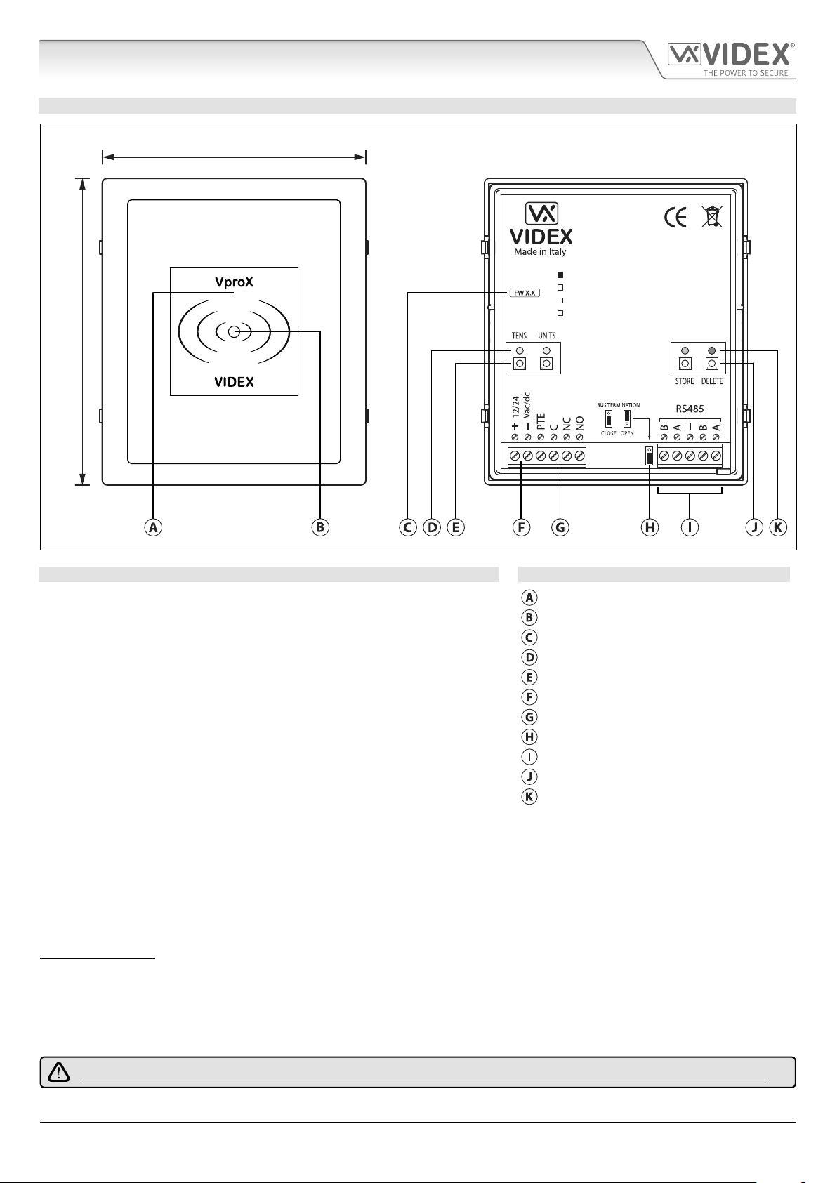
Art. 4850R Technical Information
ART. 4850R PROXIMITY READER MODULE
103mm
4850R
120mm
Fig. 17
DESCRIPTION LEGEND
The Art.4850R proximity reader is an expansion reader that can be connected to
the Art.4810 GSM PRO intercom via an RS485 bus connection. It allows the GSM
intercom to have up to 7 additional proximity access doors or can be used with
a combination of proximity and coded access using the Art.4903 keypad (up to
a total of 8 devices with the GSM PRO’s onboard reader as device ID.1).
The front of the module has a tri-colour LED to indicate to the user the status of
the reader (amber = standby, green = access granted and red = access denied).
The reader is housed in a 4000 series module with a stainless steel or aluminium
surround front frame, see Fig.17.
When connected directly to the GSM PRO intercom module with the RS485 bus
connection it can be programmed by either sending SMS text messages (refer
to notes programming the GSM intercom on pages 37 - 61) or using the GSMSK
PC software (refer to the manual: GSMSK_66251720_EN_V2-0 or later).
Proximity reading area
Status indication LED
Current rmware version (FW X.X)
Programming indication LED's (yellow)
Tens and Units programming buttons
Power input terminals
PTE input & relay (C/NC/NO) terminals
RS485 bus termination jumper
RS485 bus terminals
Store and Delete programming buttons
Store LED (green) and Delete LED (red)
STEEL
ALI
HIGH BRASS
MATTE
It has a single onboard relay with common (C), normally open (NO) and normally closed (NC) connections and a switched 0V push
to exit input (PTE) to enable the activation of the relay. The relay operating time can be set for 01 - 99 seconds or 00 for latching
and can be programmed by using a combination of the tens, units and store buttons on the back of the module (also refer to
programming the relay time on page 18). Presenting a programmed fob will activate the relay for the programmed relay time.
The unit ID (1 - 8) can be set by using a combination of the units, store and delete buttons on the back of the module (also refer to
setting the unit ID on page 18).
IMPORTANT NOTE: The Art.4850R reader can only be used as an expansion reader for the GSM PRO intercom, therefore
programming can only be carried out (when connected by RS485) by sending SMS text messages to the GSM PRO or using the
GSMSK PC software (software version 4.0.0.0 or later). The only manual programming that can be performed on the module is
the unit ID setup and relay time. All proximity fob data is actually stored in the GSM module’s memory and not the proximity
reader.
Compatible key fobs: 955/T and/or PBX-1E ; compatible proximity cards: 955/C and/or PBX-2.
IMPORTANT NOTE: MIFARE PROXIMITY FOBS/CARDS CANNOT BE USED WITH THIS READER.
4000 Series GSM Audio Intercom - Technical Manual
- 17 -
66250754-EN - V1.0 - 18/02/19
4000 Series GSM Audio Intercom with Proximity
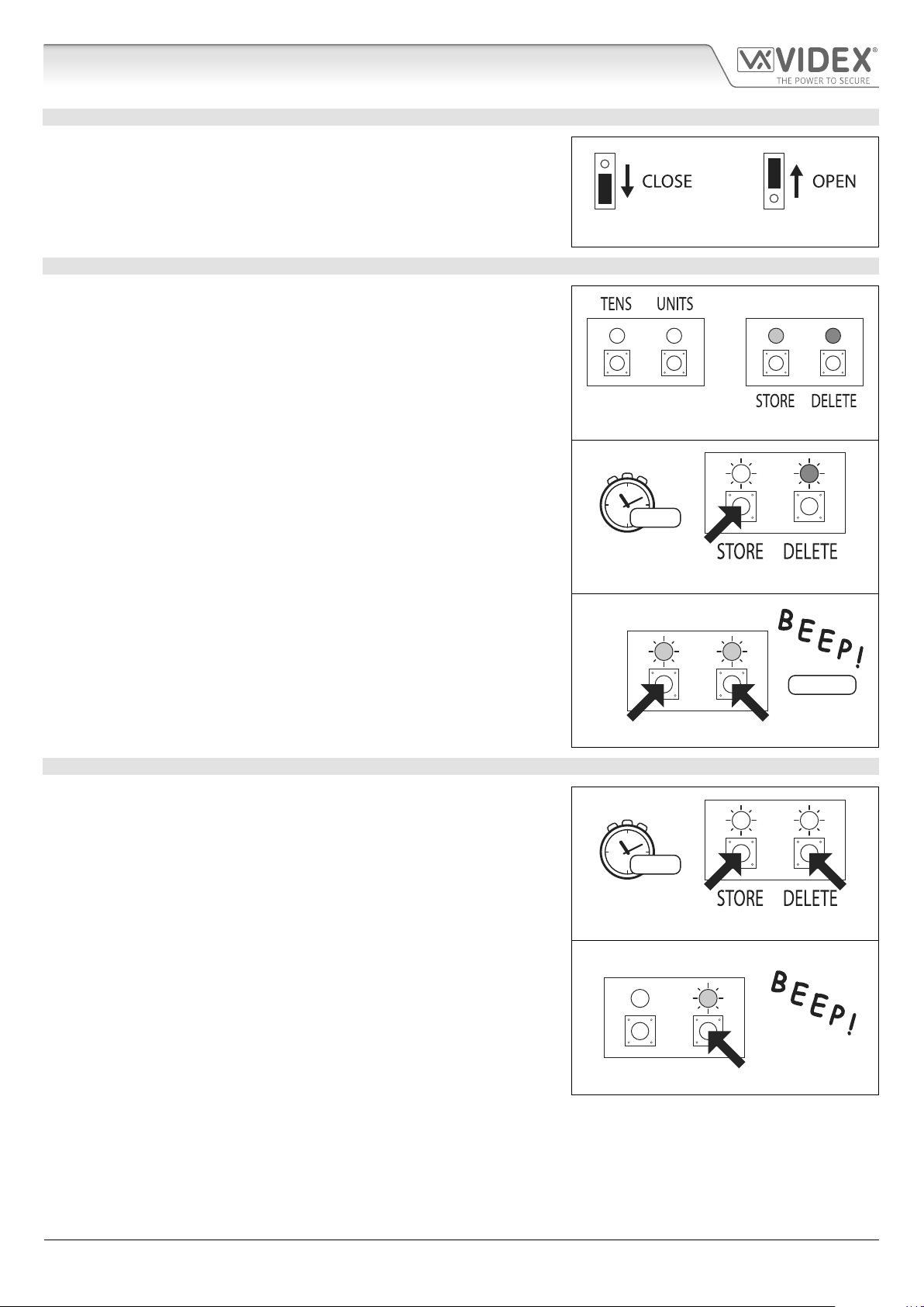
5x units2x tens
Art. 4850R Technical Information
RS485 BUS TERMINATION JUMPER
The jumper on the rear of the proximity reader sets the RS485 bus termination
when connected to the Art.4810 GSM PRO or other RS485 devices. By default
the jumper is set to the closed position (lower two pins). When more than one
RS485 device is connected to the reader in line on the RS485 bus terminals then
the jumper can be set to the open position (upper two pins) and only set to the
closed position on the end of line device, see Fig.18.
PROGRAMMING THE RELAY TIME 00, 01 99
In standby the green store LED and red delete LED on the back of the module
will be ON, the yellow tens and units LED’s will be OFF, see Fig.19. Follow the
steps below to set the relay time:
1. Press and hold down the store button for approximately 6 seconds until the
green store LED switches OFF and the red delete LED stays ON, see Fig.20;
2. Use the tens and units buttons to set the relay time, e.g. to set the relay time
to 25 press the tens buttons twice and the units button 5 times (listen for the
conrmation beep each time the button is pressed and observe the yellow
tens/units LED’s as they should ash each time that each button is pressed),
see Fig.21;
Fig. 18
Fig. 19
3. Press the store button once to conrm the setting (again listen for the
conrmation beep when the button is pressed and observe the green store
LED as this should ash once);
4. Both the green store LED and red delete LED will switch back ON and put the
reader back into standby;
5. The reader is ready to be programmed.
To set the relay time for latching press and hold down the store button (follow
step 1 above). Once the red delete LED stays ON and the green store LED is OFF,
press the store button once to conrm (follow step 3 above). The relay time will
be set for 00 seconds.
SETTING THE UNIT ID 1 8
In standby the green store LED and red delete LED on the back of the module
will be ON, the yellow tens and units LED’s will be OFF, see Fig.19. Follow the
steps below to set the unit ID:
1. Press and hold down both the store and delete buttons for approximately 6
seconds until both the green and red LED’s switch OFF, see Fig.22;
2. Use the units button to set the unit ID of the reader, e.g. to set the unit ID to
5 press the units button 5 times (listen for the conrmation beep each time
the button is pressed and observe the yellow units LED as this should ash
each time the button is pressed), see Fig.23;
3. Press the store button once to conrm the setting (again listen for the
conrmation beep when the button is pressed and observe the green store
LED as this should ash once);
4. Both the green store LED and red delete LED will switch back ON and put the
reader back into standby;
5. The reader is ready to be programmed.
6 secs...
Fig. 20
TENS UNITS
set 25 secs.
Fig. 21
6 secs...
Fig. 22
TENS UNITS
Fig. 23
4000 Series GSM Audio Intercom - Technical Manual
- 18 -
66250754-EN - V1.0 - 18/02/19
4000 Series GSM Audio Intercom with Proximity
Art. 4850R Technical Information
TERMINAL CONNECTIONS TECHNICAL SPECIFICATION
Connection Description Working voltage: 12V - 24Vac/dc +/- 10%
+ 12-24V AC or DC power input Current (standbay): 150mA
- 0V power input Current (operation): 150mA (max.)
PTE Switched 0V input to trigger relay Number of relays: 1x, C, NC and NO
C Relay common connection
NC Relay normally closed connection Push to exit inputs: 1x, PTE (switched 0V)
NO Relay normally open connection RS485 bus connections: 2x A, 2x B and - (GND)
B
A Networkable: via RS485 (up to 8 devices max.)
RS485 bus terminal connections
3A @
24Vac⁄dc
max.
- RS485 ground connection Programming: Tens, units, store & delete buttons
B
A
RS485 bus terminal connections
Relay current⁄voltage: 3A @ 24Vac/dc (max.)
RS485 termination: Yes, Jumper
(for unit ID & relay time only)
Working Temperature: -10 +50
o
C
4000 Series GSM Audio Intercom - Technical Manual
- 19 -
66250754-EN - V1.0 - 18/02/19
4000 Series GSM Audio Intercom with Proximity
Wiring Diagrams
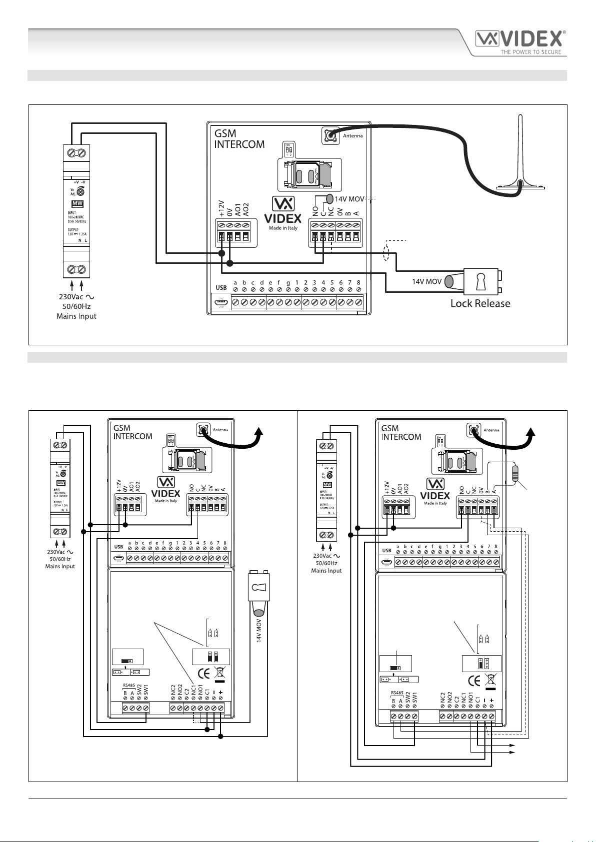
GSM4K CONNECTIONS
Fig.24 shows the wiring connections for a GSM4K-1/GSM4K-1S audio kit.
For fail secure locks a
MOV must also be tted
across terminals C & NO and
for fail safe locks across C & NC.
For fail safe lock wiring move
lock wire from NO to NC.
Fig. 24
GSM4KCR CONNECTIONS
Fig.25 shows the wiring connections for a GSM4KCR-1/GSM4KCR-1S audio kit when the Art.4903 is used as a standalone keypad.
Fig.26 shows connections for a GSM4KCR-1/GSM4KCR-1S audio kit when the additional access code features of the GSM PRO
module are required when connecting it with the RS485 bus terminals to the Art.4903 keypad.
Art.4810
Art.4903
For fail safe lock wiring move lock
wire from NO1 to NC1 and move
JP2 jumper to the NC1 position
To Antenna
Fail Secure
Lock Release
Art.4810
Art.4903
For volt free contacts to gate
controls remove JP2 jumper
To Antenna
120Ω resistor
tted across A & B
unless connected
to an Art.481
MOV
NO2 NC2
NO1 NC1
OFFON
RS485 BUS TERMINATION
Fig. 25 Fig. 26
4000 Series GSM Audio Intercom - Technical Manual
- 20 -
RS485 bus termination
jumper in ON position
OFFON
RS485 BUS TERMINATION
MOV
NO2 NC2
NO1 NC1
RS485 bus cable
(2 core twisted or CAT-5 where: 1 core = A, 1 core = B, 1 pair = 0V/GND)
Volt Free
Contacts
66250754-EN - V1.0 - 18/02/19
4000 Series GSM Audio Intercom with Proximity
Wiring Diagrams
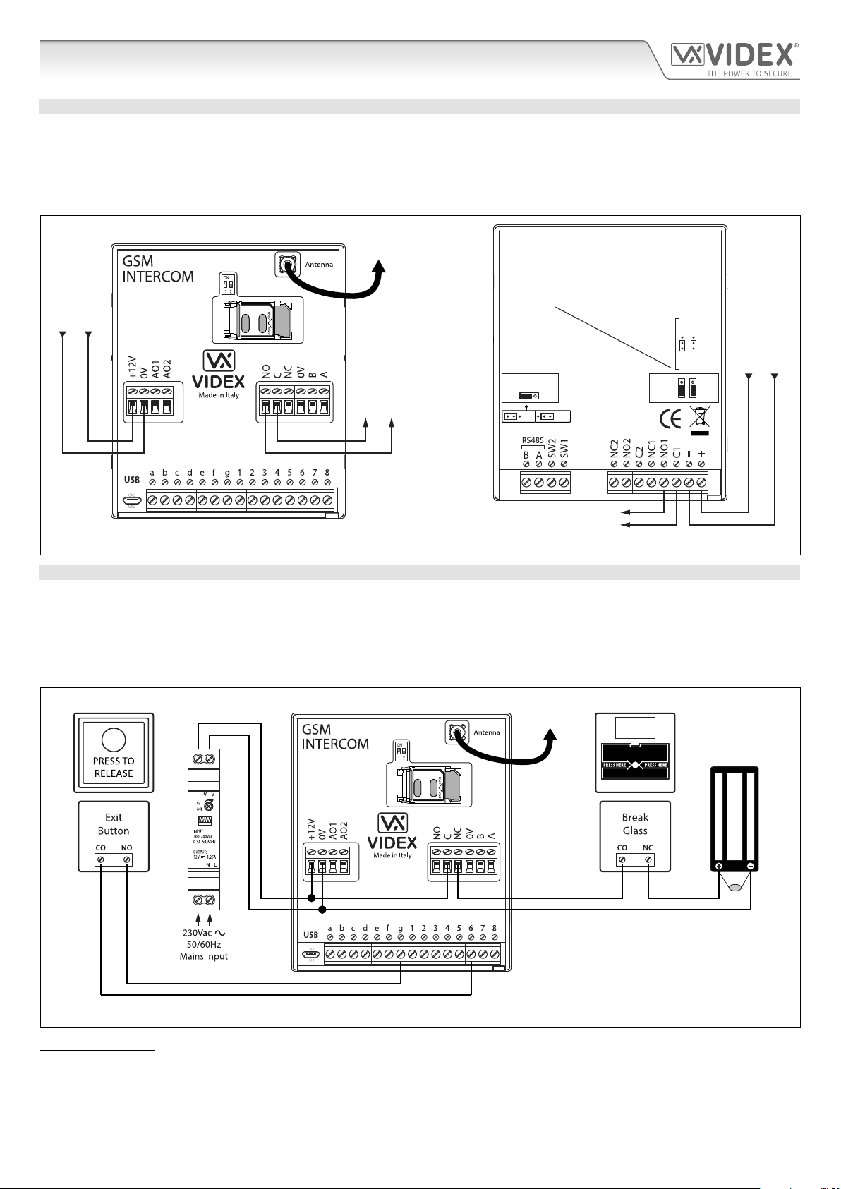
CONNECTING TO A GATE CONTROLLER
For a GSM4K series audio kit if the Art.4810 GSM intercom is going to be connected to an electric gate then the wires from the gate
controls can be connected directly into the C and NO relay terminals on the GSM module, as shown in Fig.27. For a GSM4KCR series
audio kit if the gate controls are going to be connected directly to the Art.4903 keypad the relay terminals C1 and NO1 can be used
(or C2/NO2 depending on the relay required), remembering to remove the respective back EMF protection jumper (JP2 or JP3), as
shown in Fig.28.
To
Art.4903
Antenna
Art.4810
0V (GND)
+12Vdc
Volt Free connections
to gate controls
Art.4903
When using relay 1 connections C1/NO1
to gate controls remove JP2 jumper (if
using relay 2 [CO2/NO2] remove JP3
jumper)
MOV
NO2 NC2
RS485 BUS TERMINATION
Volt Free connections
OFFON
to gate controls
NO1 NC1
+12Vdc
0V (GND)
Fig. 27 Fig. 28
CONNECTING A PUSH TO EXIT BUTTON AND A BREAK GLASS UNIT
The push to exit button must be congured as a “push-to-make” switch and connected across terminals g & 6 on the Art.4810 GSM
PRO module. The break glass unit, congured as a “push-to-break”, would only be used when connecting a fail safe/fail open lock
release (e.g. a mag lock) and would connect in series with the GSM’s relay connections C and NC, as shown in Fig.29.
When the exit button is pressed the GSM relay will trigger for the programmed relay time. When the break glass unit is activated it
will break the power to the mag lock.
To
Antenna
Art.4810
Fig. 29
EMERGENCY
DOOR RELEASE
Emergency Break Glass
12Vdc
MAG LOCK
14-20V
MOV
IMPORTANT NOTE: In instances where the current draw of the lock (fail secure or fail safe) exceeds the current rating of the
HDR15-12 (1.25A) power supply a separate power supply with a sucient current rating will be required to power the lock.
4000 Series GSM Audio Intercom - Technical Manual
- 21 -
66250754-EN - V1.0 - 18/02/19
4000 Series GSM Audio Intercom with Proximity
Auxiliary Inputs/Outputs
AUXILIARY OUTPUT AO1
The auxiliary output AO1 has six modes 00 - 05 and is set using the A1M command (refer to page 43 for full list of A1M programming
modes). It is an open collector output (switched low, 150mA max.) and depending on the mode it is set to will determine how the
AO1 output behaves. The following examples show how the AO1 output can be connected.
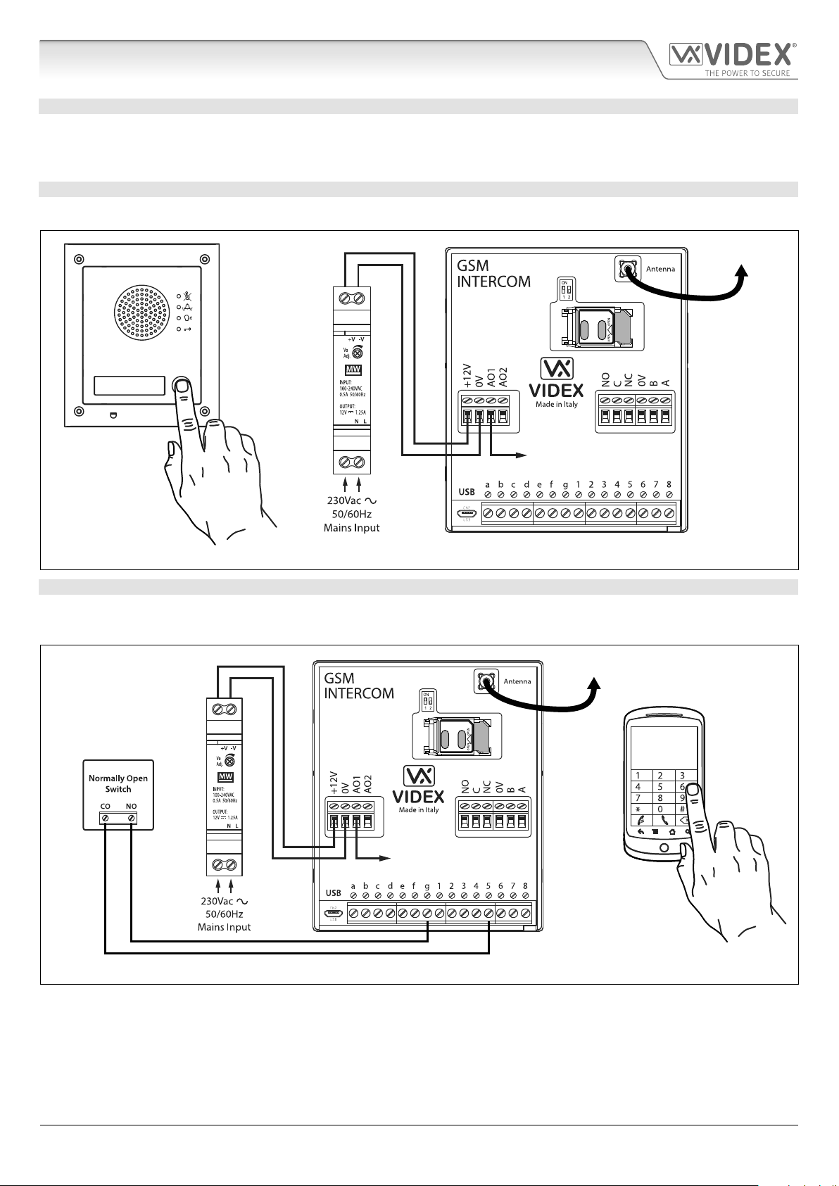
AO1 SET TO MODE 00, ‘CALL ACTIVATED’
When set to mode 00 auxiliary output AO1 will activate when the call begins and deactivate when the call ends, as shown in Fig.30.
To Antenna
Art.4810
AO1 output will activate
for the duration of the call
Fig. 30
AO1 SET TO MODE 01, ‘USER ACTIVATED’
When set to mode 01 auxiliary output AO1 will activate when the terminals g & 5 are shorted together on the GSM PRO module or
by pressing 6 on the telephone during a call, as shown in Fig.31. Auxiliary output AO1 will only activate for the programmed time.
To Antenna
Art.4810
OR
AO1 output will activate
for the programmed time
Fig. 31
4000 Series GSM Audio Intercom - Technical Manual
- 22 -
66250754-EN - V1.0 - 18/02/19
4000 Series GSM Audio Intercom with Proximity
Auxiliary Inputs/Outputs
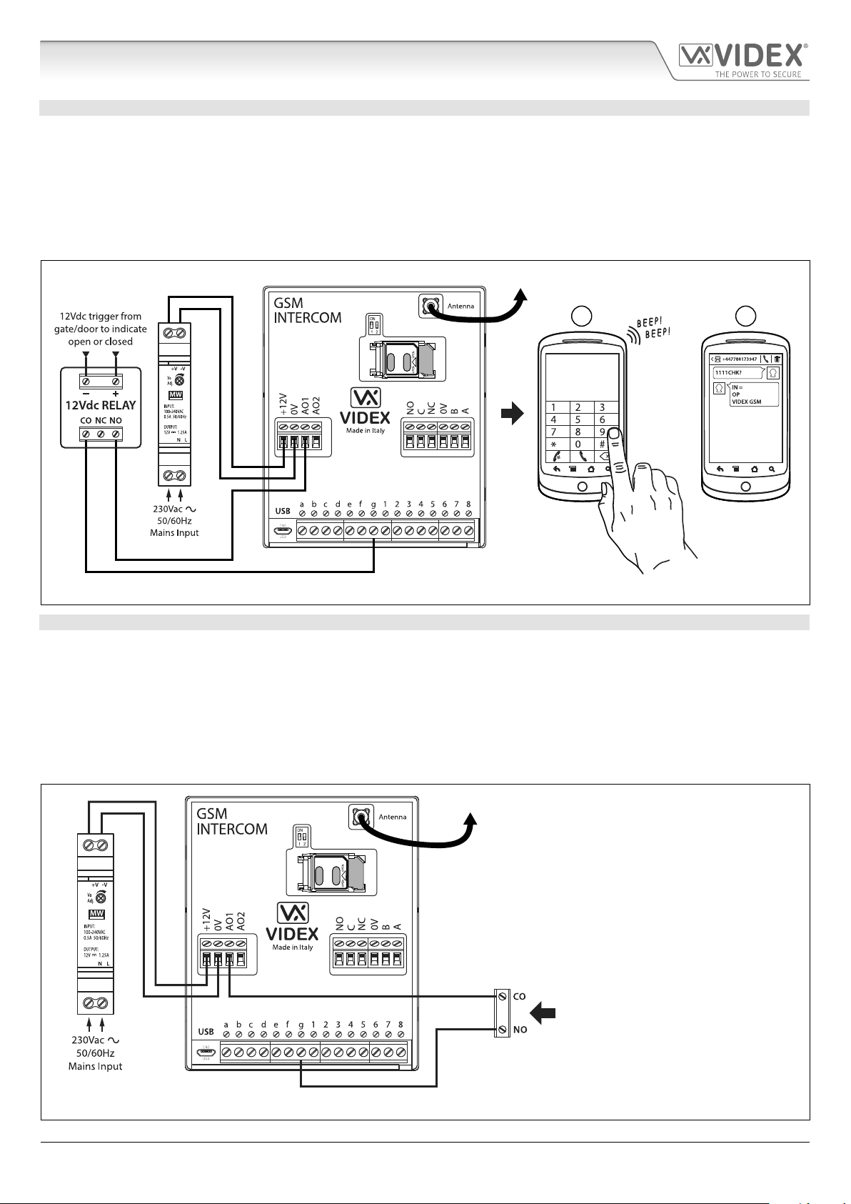
AO1 SET TO MODE 02, ‘STATUS INDICATION’
When set to mode 02 auxiliary output AO1 is used exclusively as a monitoring input. For example, checking if a gate/door is open
or closed. Once set the AO1 input status can be interrorgated in two ways:
1. During a call: press 9 on the telephone keypad and listen to the number of beeps in the ear piece. One beep indicates the input
is closed and two beeps indicates the input is open.
2. At anytime: send the SMS message 1111CHK? to the GSM PRO intercom. An SMS message will be returned with IN=OP for
open or with IN=CL for closed.
For this feature an additional relay will be required and the AO1 input must be wired as shown in Fig.32.
To Antenna
1 2
Art.4810
OR
Fig. 32
AO1 SET TO MODE 03, ‘DIVERT CALLS TO MASTER NUMBER’
It is possible to have the GSM PRO call buttons diverted to the master number (outside certain hours) using the TBA timeband
feature (refer to timeband TBA programming notes on page 47). Alternatively it is possible to divert the GSM PRO call buttons to
the master number when auxiliary output AO1 has been set to mode 03 (auxiliary output AO1 is used as a monitoring input). In
this instance a switched common and normally open (CO/NO) trigger needs to be used to enable or disable ‘divert calls to master
number’ and the auxiliary output AO1 must be wired as shown in Fig.33. In either case a master number is required following the
STM store master number feature (refer to STM programming notes on page 46).
If there is no master number stored, the intercom will beep and the busy LED will ash once to indicate no call is taking place (if the
speech board is switched ON, the GSM PRO module will announce “the phone is switched o please try later”).
To Antenna
Art.4810
Normally open (NO) switched input to
enable and disable divert to master number
Fig. 33
4000 Series GSM Audio Intercom - Technical Manual
- 23 -
66250754-EN - V1.0 - 18/02/19
4000 Series GSM Audio Intercom with Proximity
Auxiliary Inputs/Outputs
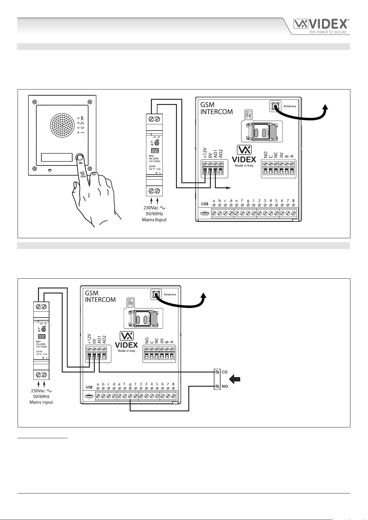
AO1 SET TO MODE 04, ‘CALL ACTIVATED TIMED’
Similar to mode 00, however, when set to mode 04 auxiliary output AO1 will activate when the call begins and deactivate when the
auxiliary AO1 time expires, see Fig.34.
The auxiliary output AO1 time can be set using the SMS programming code 1111A1Tnn? (where nn = time in seconds, also refer to
notes programming the GSM intercom on pages 37 - 61) or setup by using the GSMSK PC programming software.
To Antenna
Art.4810
AO1 output will activate
for the programmed time
Fig. 34
AO1 SET TO MODE 05, ‘ENABLE/DISABLE DIAL TO OPEN NUMBERS’
When the auxiliary output AO1 mode is set to 05 the dial to open numbers will only activate the GSM relay when a common and
normally open (CO/NO) switch connected across terminals g & AO1, as shown in Fig.35, is open circuit. When the switch is closed
and terminals g & AO1 are short together this will disable the dial to open numbers.
To Antenna
Art.4810
Normally open (NO) switched input to
activate and deactivate dial to open numbers
Fig. 35
IMPORTANT NOTE: When auxiliary output AO1 is set to a particular mode (00 - 05) it cannot be used as an input/output for
anything else.
4000 Series GSM Audio Intercom - Technical Manual
- 24 -
66250754-EN - V1.0 - 18/02/19
 Loading...