

Videx ESVK-1S/6388, ESVKC/6388 Series, ESVK-2/6388, ESVK-2S/6388, ESVKX-1/6388 Installation Handbook
...Page 1
VIDEOKIT
ESVK/6388 SERIES
“2 Wire” bus one way, two way videokit
ESVK
ESVKX
ESVKC
Rev.0.1
Installation handbook
66550033-EN - V4.0 - 15/02/19
6388
We recommend
This equipment is installed by a
Competent Electrician, Security or
Communications Engineer
.
Page 2
ESVK/6388 Series “2 wire Bus” videokit
Index
System components and available versions ................................................................................................................................ 3
General directions for installation ................................................................................................................................................ 6
Art.4333/4333X Speaker unit module with built-in functional to digital interface ................................................................. 8
Art.4800 - 4800M Digital codelock module ............................................................................................................................... 13
4000 Series surface and ush mounting door station installation .......................................................................................... 16
Art.6388 3.5" colour display videophone ................................................................................................................................. 18
6300 Series Videophone wall mounting instructions ............................................................................................................... 22
Art.2321-2321/P Power supplies for VX2300 .......................................................................................................................23
Art.2322 Power supply converter from BUS line to 12 Vdc ......................................................................................................24
Art.125 Call expansion module .................................................................................................................................................. 25
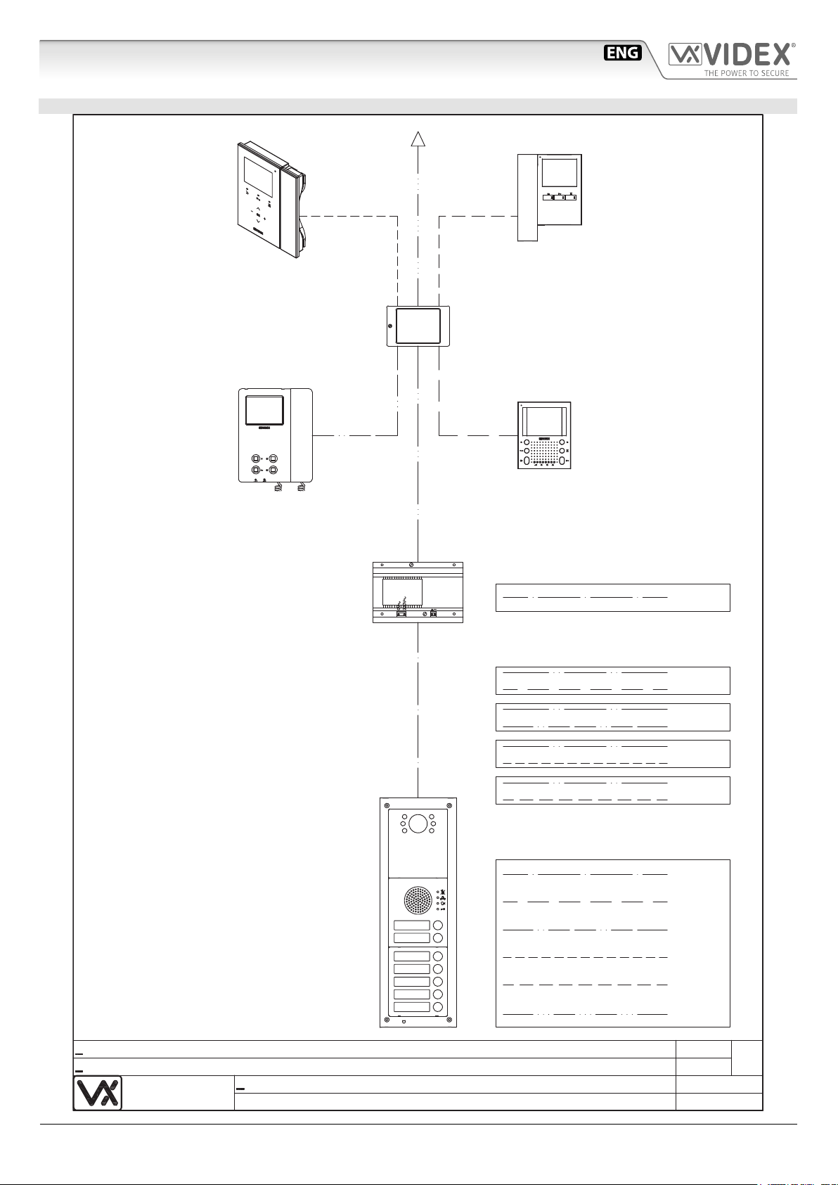
Installation diagrams ................................................................................................................................................................... 77
NOTES AND SUGGESTIONS
• All diagrams refer to all kits versions: ush or surface, colour or black & white.
• Dashed connections refer to optional connections (“Local bell”, “Push to exit” & “Door monitor”).
• Some diagrams show how to connect a 12Vdc electric lock: these directions are suitable for all diagrams in this manual.
• Each time a setting is changed on a videophone (address, extension, number of rings etc.), the videophone must be disconnected from
the relevant connection board then after a few seconds reconnected again to allow the recognizing of the new setting.
• All diagrams shown are valid for B&W or colour systems with surface or ush mount door station.
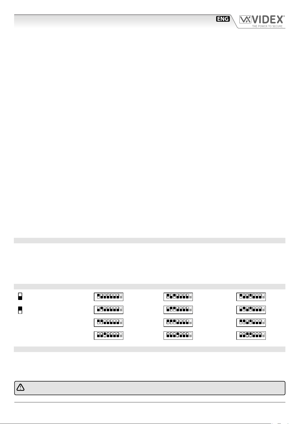
ADDRESSES 1..12 TABLE FOR DIPSWITCH BANKS WITH ON POSITION UP
= OFF
= ON
1
2
3
4
ON
1
4 5
2 3
6 7 8
ON
1
4 5
2 3
6 7 8
ON
1
4
2 3
6 7 8
5
ON
2 3
4 5
6 7 8
1
5
6
7
8
ON
2 3
2 3
2 3
2 3
4 5
4 5
4 5
4 5
6 7 8
6 7 8
6 7 8
6 7 8
1
ON
1
ON
1
ON
1
9
10
11
12
ON
1
4 5
2 3
6 7 8
ON
2 3
2 3
2 3
4 5
4 5
4 5
6 7 8
6 7 8
6 7 8
1
ON
1
ON
1
DECLARATION OF RESPONSIBILITY
This manual has been written and revised carefully. The instructions and the descriptions which are included in it are referring to
VIDEX parts and are correct at the time of print. However, subsequent VIDEX parts and manuals, can be subject to changes without
notice. VIDEX Electronics S.p.A. cannot be held responsible for damages caused directly or indirectly by errors, omissions or discrepancies between the VIDEX parts and the Manual.
WE RECOMMEND
This equipment is installed by a Competent Electrician, Security on Communications Engineer
ESVK/6388 Series - Installation handbook
- 2 -
66550033-EN - V4.0 - 15/02/19
Page 3
ESVK/6388 Series “2 wire Bus” videokit
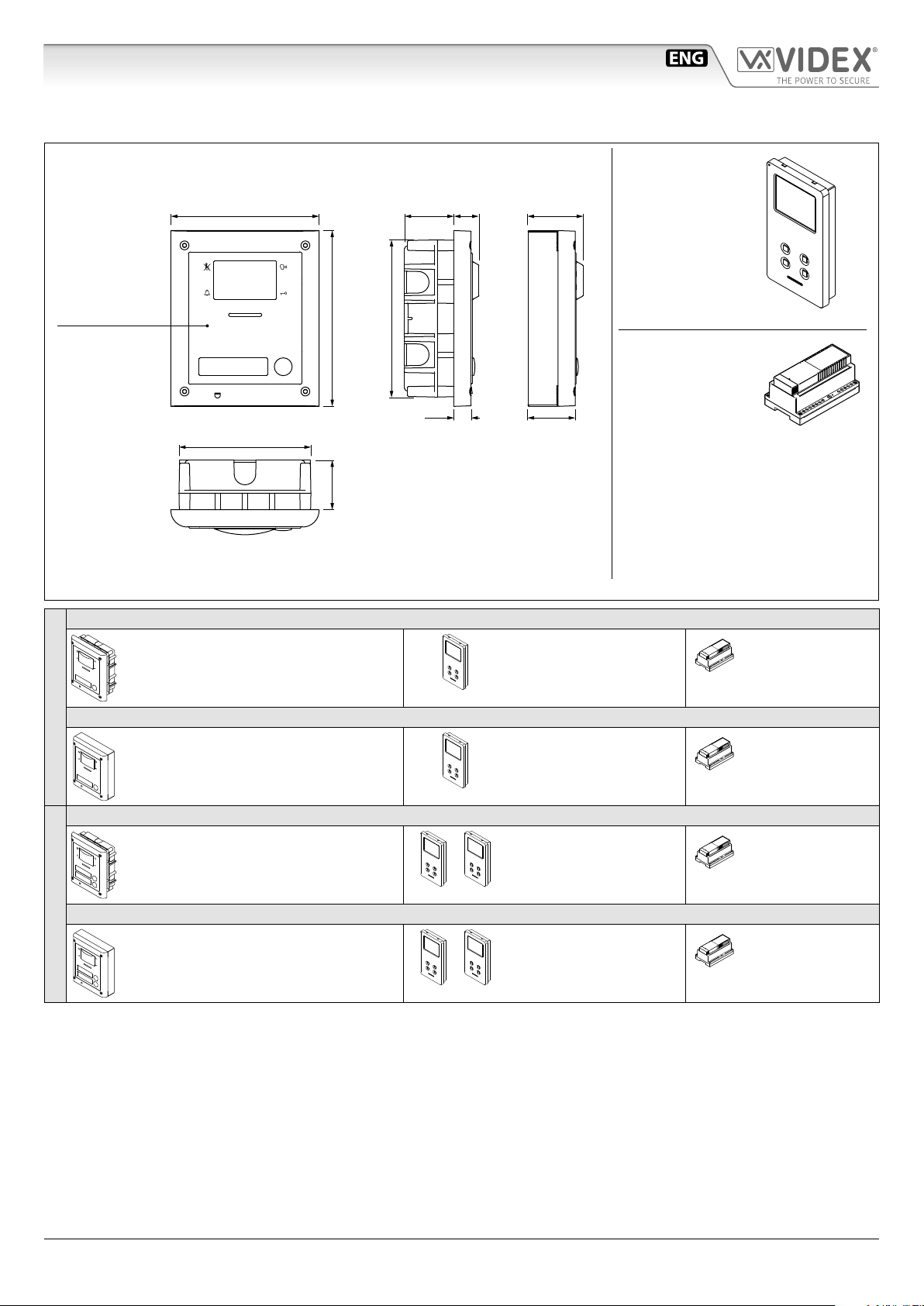
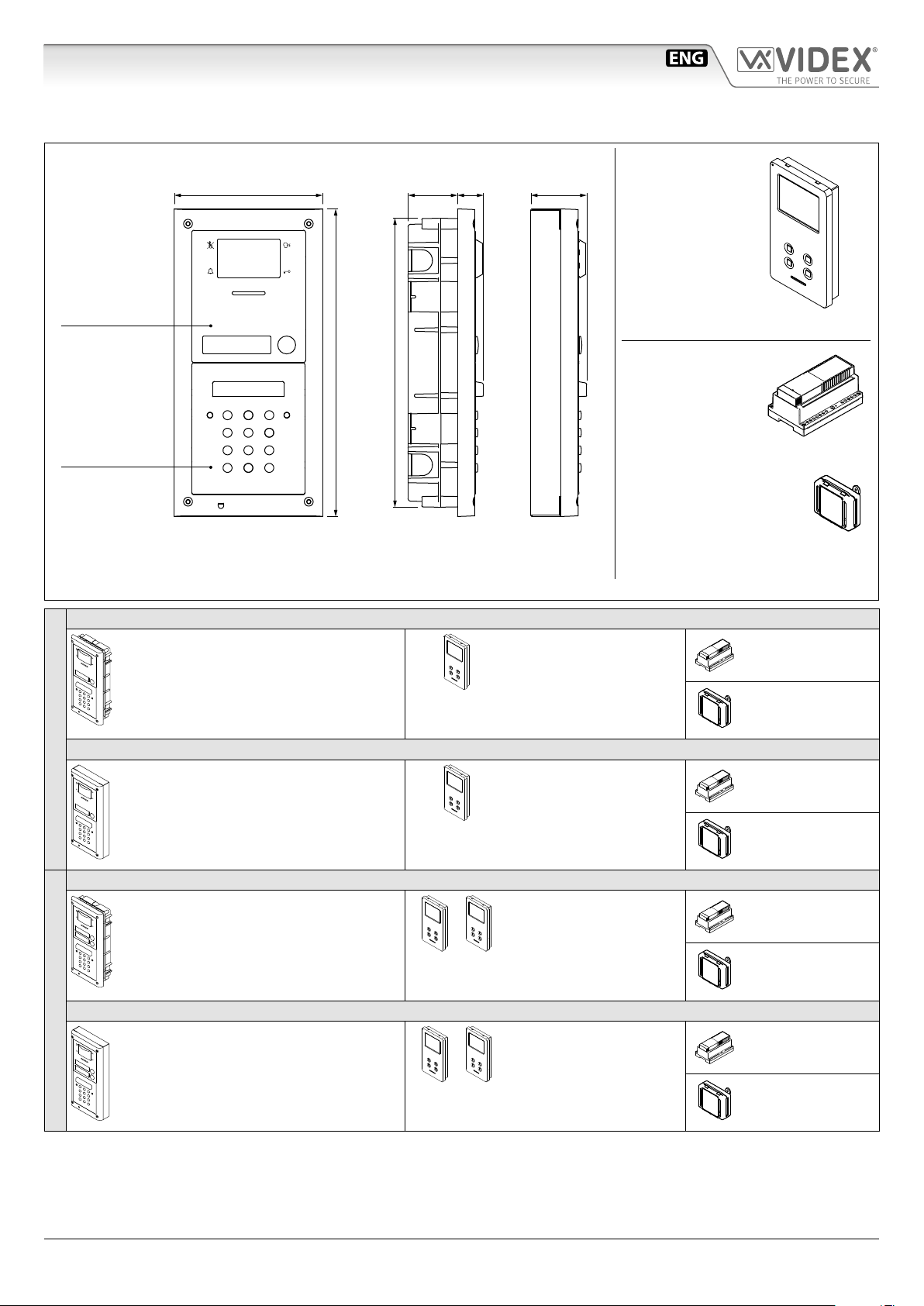
System components and available versions
ESVK/6388
OUTDOOR
STATION
Camera unit
Art.4333
pag. 8
Colour videokit.
135,0
160,0
120,0
45,0
45,0 22,7
143,0
15,7
Flush
Mounting
50
43,8
Surface
Mounting
INDOOR
STATION
Videomonitor
Art.6388
pag. 18
ACCESSORIES
Power supply
Art.2321
pag. 23
Fig. 1 - ESVK/6388 components (measures in mm)
ESVK-1/6388 - ush mounting
1 Outdoor station composed of:
1 Art.4333-1: 1 button camera unit
1 Art.4851: Flush mounting box
ESVK-1S/6388 - surface mounting
1 Outdoor station composed of:
ONE WAY VERSIONS
ESVK-2/6388 - ush mounting
ESVK-2S/6388 - surface mounting
TWO WAY VERSIONS
1 Art.4333-1: 1 button camera unit
1 Art.4881: Surface mounting box
1 Outdoor station composed of:
1 Art.4333-2: 2 buttons camera unit
1 Art.4851: Flush mounting box
1 Outdoor station composed of:
1 Art.4333-2: 2 buttons camera unit
1 Art.4881: Surface mounting box
1 Colour videomonitor
Art.6388
1 Colour videomonitor
Art.6388
2 Colour videomonitors
Art.6388
2 Colour videomonitors
Art.6388
1 Power supply
Art.2321
1 Power supply
Art.2321
1 Power supply
Art.2321
1 Power supply
Art.2321
ESVK/6388 Series - Installation handbook
- 3 -
66550033-EN - V4.0 - 15/02/19
Page 4
ESVK/6388 Series “2 wire Bus” videokit
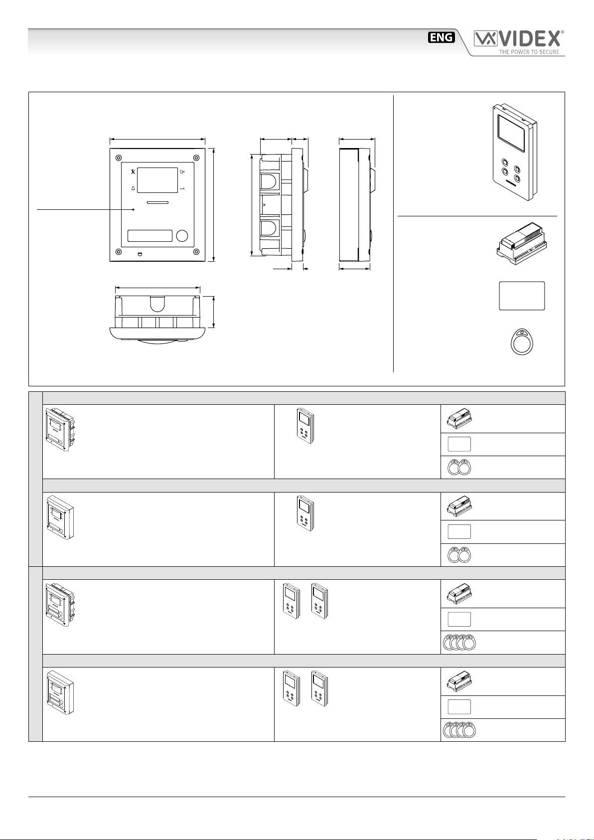
System components and available versions
ESVKX/6388 Colour videokit with embended proximity key reader.
OUTDOOR
STATION
135,0
Camera unit
Art.4333X
pag. 8
120,0
Fig. 2 - ESVKX/6388 components (measures in mm)
160,0
45,0
45,0 22,7
143,0
15,7
Flush
Mounting
50
43,8
Surface
Mounting
INDOOR
STATION
Videomonitor
Art.6388
pag. 18
ACCESSORIES
Power supply
Art.2321
pag. 23
Card format fob
Art.955/C
Tag format fob
Art.955/T
ESVKX-1/6388 - ush mounting
1 Outdoor station composed of:
1 Art.4333X-1: 1 button camera unit
1 Art.4851: Flush mounting box
ESVKX-1S/6388 - surface mounting
1 Outdoor station composed of:
1 Art.4333X-1: 1 button camera unit
ONE WAY VERSIONS
1 Art.4881: Surface mounting box
ESVKX-2/6388 - ush mounting
1 Outdoor station composed of:
1 Art.4333X-2: 2 buttons camera unit
1 Art.4851: Flush mounting box
ESVKX-2S/6388 - surface mounting
1 Outdoor station composed of:
1 Art.4333X-2: 2 buttons camera unit
TWO WAY VERSIONS
1 Art.4881: Surface mounting box
1 Colour videomonitor
Art.6388
1 Colour videomonitor
Art.6388
2 Colour videomonitors
Art.6388
2 Colour videomonitors
Art.6388
1 Power supply
Art.2321
1 Card format fob
Art.955/C
2 Tag format fobs
Art.955/T
1 Power supply
Art.2321
1 Card format fob
Art.955/C
2 Tag format fobs
Art.955/T
1 Power supply
Art.2321
1 Card format fob
Art.955/C
4 Tag format fobs
Art.955/T
1 Power supply
Art.2321
1 Card format fob
Art.955/C
4 Tag format fobs
Art.955/T
ESVK/6388 Series - Installation handbook
- 4 -
66550033-EN - V4.0 - 15/02/19
Page 5
ESVK/6388 Series “2 wire Bus” videokit
System components and available versions
ESVKC/6388 Colour videokit plus a codelock module.
OUTDOOR
STATION
Camera unit
Art.4333
pag. 8
Codelock
unit
Art.4800M
pag. 13
Fig. 3 - ESVKC/6388 components (measures in mm)
280,0
45,0 24,0
263,0
Flush
Mounting
51,0135,0
Surface
Mounting
INDOOR
STATION
Videomonitor
Art.6388
pag. 18
ACCESSORIES
Power supply
Art.2321
pag. 23
Power supply converter
Art.2322
pag. 24
ESVKC-1/6388 - ush mounting
1 Outdoor station composed of:
1 Art.4333-1: 1 button camera unit
1 Art.4800M: Codelock module
1 Art.4852: Flush mounting box
ESVKC-1S/6388 - surface mounting
1 Outdoor station composed of:
ONE WAY VERSIONS
ESVKC-2/6388 - ush mounting
ESVKC-2S/6388 - surface mounting
TWO WAY VERSIONS
1 Art.4333-1: 1 button camera unit
1 Art.4800M: Codelock module
1 Art.4882: Surface mounting box
1 Outdoor station composed of:
1 Art.4333-2: 2 buttons camera unit
1 Art.4800M: Codelock module
1 Art.4852: Flush mounting box
1 Outdoor station composed of:
1 Art.4333-2: 2 buttons camera unit
1 Art.4800M: Codelock module
1 Art.4882: Surface mounting box
1 Colour videomonitor
Art.6388
1 Colour videomonitor
Art.6388
2 Colour videomonitors
Art.6388
2 Colour videomonitors
Art.6388
1 Power supply
Art.2321
1 Power supply
converter
Art.2322
1 Power supply
Art.2321
1 Power supply
converter
Art.2322
1 Power supply
Art.2321
1 Power supply
converter
Art.2322
1 Power supply
Art.2321
1 Power supply
converter
Art.2322
ESVK/6388 Series - Installation handbook
- 5 -
66550033-EN - V4.0 - 15/02/19
Page 6
ESVK/6388 Series “2 wire Bus” videokit
General directions for installation
CABLE TYPES AND CROSS SECTIONAL AREAS
The VX2300 digital system can use several types of cables but depending on their specication will allow dierent distances up to
400 meters maximum. We do not recommend the use of shielded cables because of the high eddy capacitance. It is also not advised
to double up on cables as this will also increase the capacitance. The following table species values of resistance, capacitance and
maximum distances achievable for several types of cables (capacitance and resistance values are referring to 100 metres of cable).
Cable Type** Wires Section (mm2) Resistance (Ohm) per
100 metres
VIDEX CM2 0.50 3.2 8 200m
CAT5 UTP/CW1308 0.22 8 4.9 70m
Std Telephone Cable 0.28 6.5 5.5 100m
Standard wire 0.8 / 1 2 6.5 70m
* The maximum distance represents the maximum distance from power supply. i.e. the cable length between the outdoor sta-
tion and the power supply or between the power supply and the videophone.
There are two important characteristics to consider when calculating cable, the resistance and the capacitance. The resistance
of the cable from power supply to end point must be less than 10 Ohms and can be calculated from point to point. The capacitance of the cable must not exceed 40nF and is an accumulation of all lengths and branches of the cable. For example: Videx
CM2 cable can be used for a maximum distance of 200m from door station to power supply and another 200m from power
supply to videophone (400 meters) but this distance may be reduced if the maximum capacitance is reached rst.
When using the block exchanger art. 2306 it is possible to exceed the limit of 400m. The 2306 breaks the system into
smaller systems or blocks, each block can then achieve the 400m.
For example: in a system with two block exchangers:
• Using 100m to reach the rst block, you can then use up to 300m cable in the block;
• Assuming you are using another 50 meters cable to get from the rst to the second block, in the second you can use
(400-100-50) = 250m.
** It is important that the video intercom system cables do not run with mains or other high power cables. Noise from such
cables (electromagnetic interference) may cause noises on audio/video and lost functionality. In cases where this advice
can not be followed or when existing cables are to be used it will be necessary to carry out tests to assess the quality and
functionality of the installation.
Capacitance (nF) per
100 metres
*Maximum Distance
(metres)
In case of use of cables not in conformity with above specication it is possible to experience deterioration of digital and video signals.
We suggest to use twisted cables with maximum resistance of 10 Ohm (between the furthest door station and the furthest videophone) and maximum capacitance of 40nF (this value must be calculated considering all the cables used in the system; the capacitance/metres value is normally specied on the cable package or directly on the cable).
BUS DEVICE SETUP AND VIDEO DISTRIBUTION
• When changing dip switch settings, disconnect the device from the bus for a minimum of 1 minute to allow the unit to fully discharge.
• When you have more than one device in the same apartment, all the devices must be connected to the same video distributor (Art.317N):
this means that you cannot use two video distributors Art.318 for one apartment where you have 3 or 4 videophones/intercoms.
• After completing the installation proceed to testing. The video level gain can be adjusted at several points including distributors,
entrance exchanger and bus boosters.
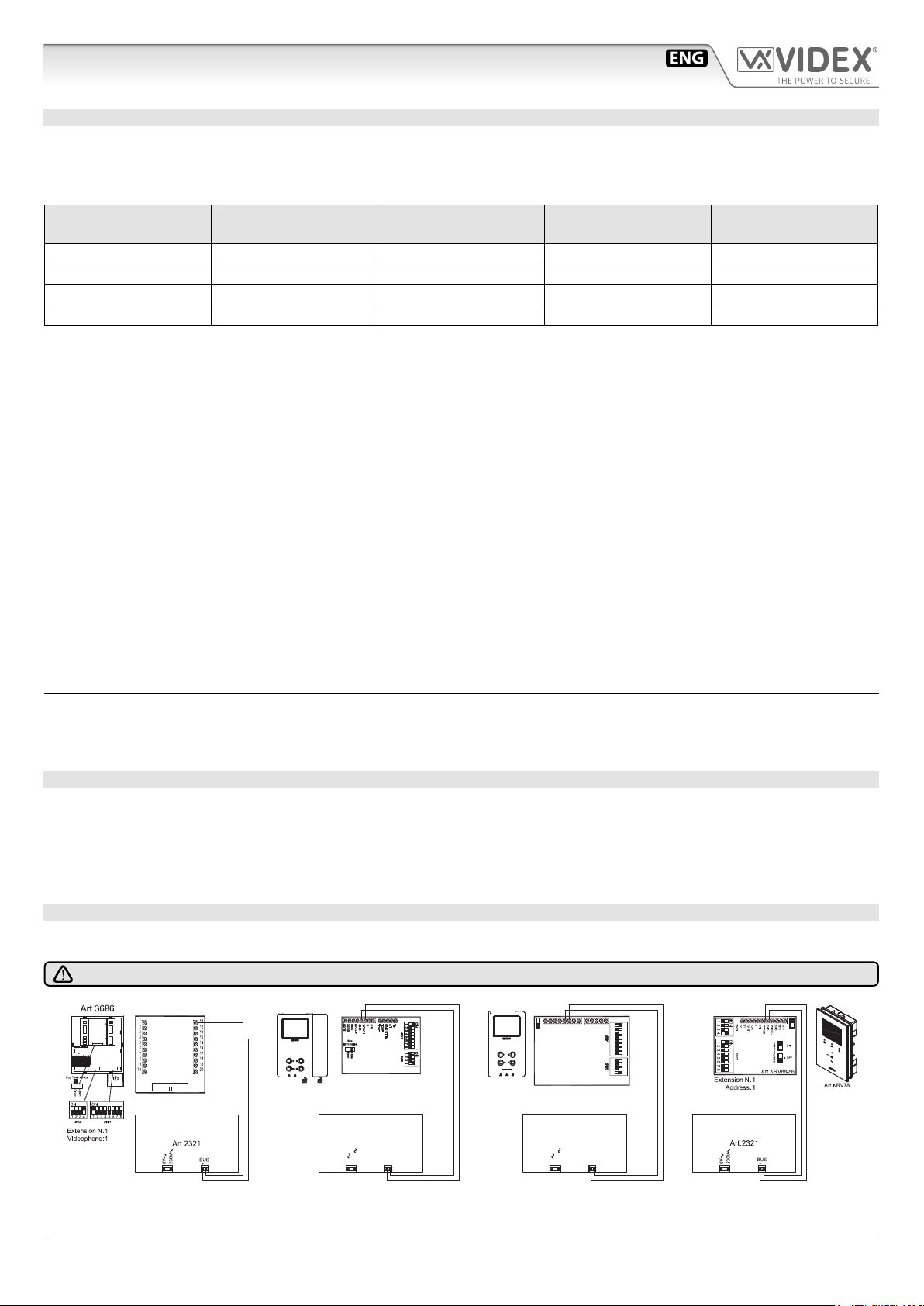
HOW TO CONNECT A LOCAL POWER SUPPLY
The drawing below shows how to connect a local power supply when required (i.e. when you have 4 videophones with the same
address that must be switched on at the same time). In both cases switch 4 of SW3 must be set to the ON position.
NOTE! OBSERVE CONNECTION POLARITIES AS SHOWN IN THE DIAGRAM BELOW.
ON
21
LB
AL
NO
3 8
-DOL
+DOL
4
5
AL-LB GND
6
7
ON
21
3
4
ART.6286
Extension N.11
Videophone:
GND
BUS1
BUS2
JP1
+12VM
ART.6388
Extension N.
Videophone:
C
GND
+VAUX
1
1
ESVK/6388 Series - Installation handbook
Art.2321
230V
0V
BUS
+
_
- 6 -
Art.2321
230V
0V
BUS
+
_
66550033-EN - V4.0 - 15/02/19
Page 7
ESVK/6388 Series “2 wire Bus” videokit
General directions for installation
CABLES LENGTH
Art.KRV86
Art.6286
Art.3686
Art.317N
Art.SL5488N
Art.2321
Using Cable CM2 - Usando Cavo CM2
BUS
= Max 200m
Using Cable CM2 - Usando Cavo CM2
+
+
+
+
= Max 200m
= Max 200m
= Max 200m
= Max 200m
Using Cable CM2 - Usando Cavo CM2
+
+
+
= Max 400m
+
Titolo:
Videx Electronics S.p.A.
Via del Lavoro 1, 63846 Monte Giberto (FM)
+
-
+
Notes:
Note:
ESVK/6388 Series - Installation handbook
- 7 -
+
Data creazione:Title:
02/07/2014
Data modifica:
02/07/2014
Autore:
Marco Rongoni
Cod.File:
VX2300CL.dwg
Foglio
/ 11
66550033-EN - V4.0 - 15/02/19
Page 8
ESVK/6388 Series “2 wire Bus” videokit
Balance
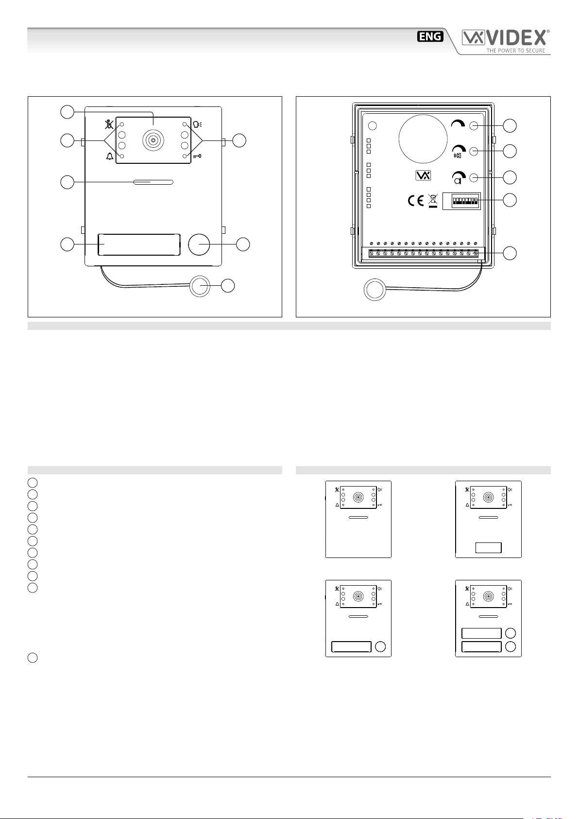
Art.4333/4333X
Speaker unit module with built-in functional to digital interface
Rev.0.1
A
G
B B
C
ED
4333-0
4333-1
4333-2
4333X-0
4333X-1
4333X-2
STEEL
ALI
HIGH BRASS
MATTE
+V2
VID2
GNDV
EB2
Made in Italy
EB1
GND
BUS
BUS
PTE
GND
GND
ON
1 2 3 4 5 6 7 8
C
NO
H
I
J
VAUX
+C
NC
K
F
Fig. 1
Fig. 2
DESCRIPTION
Speaker unit module with built-in colour camera with autoiris lens and white light illumination LEDs. Depending on the speaker
unit version it includes one or two call push buttons. The unit circuitry incorporates:
• An embedded proximity key reader (Art.4333X only);
• The transmitting amplier with microphone and volume control;
• The receiving amplier with volume control;
• The audio balance circuit with “BALANCE” control;
• The enslavement relay to enable the electric lock (3 contacts: common, normally open and normally closed). It can work also as
capacitor discharge to supply directly the electric lock;
• The call buttons from 1 to a maximum of 2 depending on the module version;
• The illumination LEDs for the card name holder;
• The camera comprised of illumination LEDs.
MODULE DETAILS:
A
Camera with illumination LEDs;
B
Operation LEDs;
C
Loudspeaker;
D
Card name holder with built-in proximity reader;
E
Call push button (0, 1 or 2 depending on the model);
F
Microphone;
G
Balance Control;
H
Loudspeaker volume control;
I
Microphone volume control;
J
Dip-switch to carry out the following programming:
AVAILABLE MODULE VERSIONS
Art.4333-0
Art.4333X-0
• Door station ID (switches from 1 to 3);
• Door opening time (switch 4 and 5);
• Conversation time (switch 6);
• Address order (switch 7);
• Main camera selection (switch 8);
K
System connection terminals.
Art.4333-1
Art.4333X-1
Art.4333-2
Art.4333X-2
ESVK/6388 Series - Installation handbook
- 8 -
66550033-EN - V4.0 - 15/02/19
Page 9
ESVK/6388 Series “2 wire Bus” videokit
MAX 50 cm
Art.4333/4333X Speaker unit module with built-in functional to digital interface
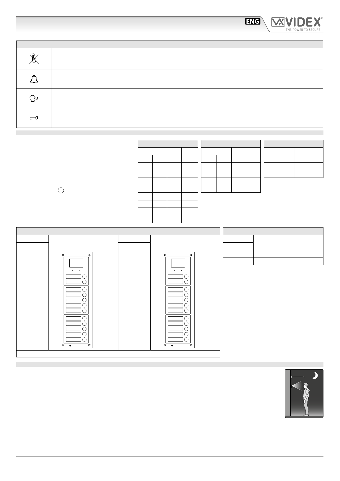
FRONT LEDS SIGNALLING DESCRIPTION
When illuminated, indicates that it is not possible to make a call because a call or a conversation is in progress (from
the outdoor station from which you are calling or from another outdoor station on systems with multiple entrances). The LED will be o when the system is in stand-by,
If illuminated, indicates that the call from the outdoor station is in progress. The LED will switch OFF when the call
is answered or after the programmed number of rings.
If illuminated, indicates that it is possible to speak because the call has been answered. The LED will switch OFF at
the end of a conversation (or at the end of the conversation time).
If illuminated, indicates that the door lock has been operated. It will switch OFF at the end of the programmed
“door opening” time.
PROGRAMMING
The programming consists of the following settings:
• Unit ID (1..8);
• Door Opening Time (1, 2, 5 or 10 seconds);
• Conversation Time (1 or 2 minutes);
• Addressing order of the buttons.
• Main camera selection
The settings are carried out through the 8 way dip-
J
switch (reference
on Fig. 2) accessible from the
rear side of the module.
OFF OFF OFF 1
OFF ON OFF 3
OFF OFF ON 5
OFF ON ON 7
UNIT ID
Switches
1 2 3
ON OFF OFF 2
ON ON OFF 4
ON OFF ON 6
ON ON ON 8
DOOR OPENING TIME
ID
Switches
4 5
OFF OFF 1
ON OFF 2
OFF ON 5
ON ON 10
Seconds
CONVERSATION TIME
Switch
6
Minutes
OFF 1
ON 2
ADDRESSES ORDER
Switch
7 7
Sort
Switch
Sort
MAIN CAMERA SELECTION
Switch
8
OFF Main camera internal
ON Main camera external
2
1
12
11
10
OFF
EB2
9
8
7
6
5
EB1
4
3
ON
Art.125 required. When Art.125 is used, follow the directions in the diagram to supply the push buttons modules.
12
11
10
9
8
EB2
7
6
5
4
3
EB1
2
1
MAXIMUM ILLUMINATION DISTANCE FROM CAMERA AT NIGHT
The illumination LED’s within the camera will illuminate the visitor when they are within 50cm of the camera.
Selection
ESVK/6388 Series - Installation handbook
- 9 -
66550033-EN - V4.0 - 15/02/19
Page 10
ESVK/6388 Series “2 wire Bus” videokit
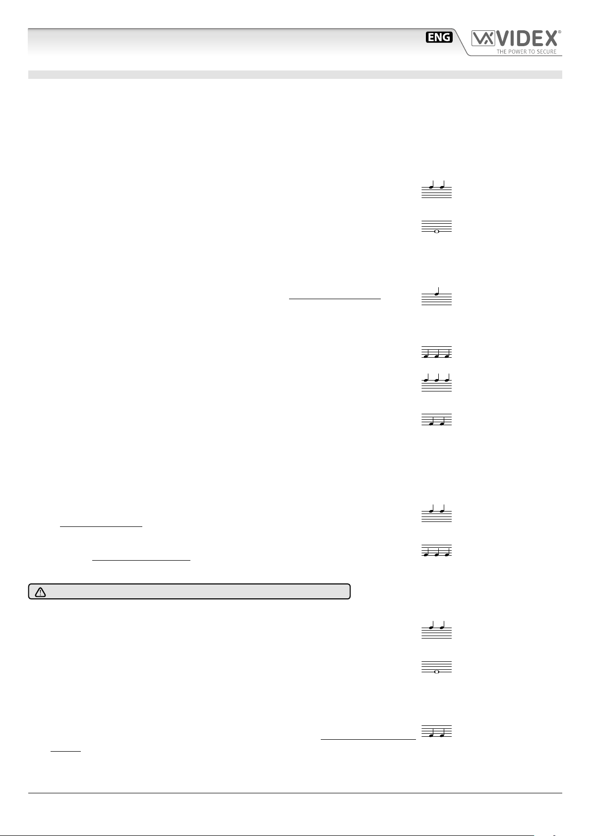
BIP BIP
BIIIIIIP
BIP
BIP BIP BIP
BIP BIP BIP
BIP BIP
BIP BIP
BIP BIP BIP
BIP BIP
BIIIIIIP
BIP BIP
Art.4333/4333X Speaker unit module with built-in functional to digital interface
PROGRAMMING TAGS FOR ART.4333X
MASTER TAG
The external module is supplied with a master tag. The master tag is programmed in-factory, it is white to easily stand out. This tag
enables user tags to be programmed or cleared.
If the master tag is lost, a new one will have to be ordered and a specic procedure performed to program it on the external module.
In this instance, it will be necessary to reprogram all the user tags.
USER TAG
The user tags can be programmed on the external module using the master tag to access programming mode:
1. Place the master tag in front of the tag reader.
↪The external module emits two high-pitched “bip”.
2. Press the call button (the lower call button in the case of a 2-button external module).
↪The external module emits a low-pitched continuous “beeping” sound.
3. Release the call button.
↪The low-pitched “beeping” sound stops.
4. Place the user tag to be programmed in front of the tag reader.
↪The external module emits a high-pitched “beeping” sound, the tag is programmed. If you do
not remove the tag quickly, may be emitted the alert for an already programmed tag.
5. Repeat the step 4 for each tag to program.
Note: the external module emits three low-pitched “beeping” sounds if an already programmed
tag is placed in front of the tag reader.
Note: the external module emits three high-pitched “beeping” sounds to indicate that its
memory is full (50 tags maximum). In this instance, it is not possible to program new tags.
6. To exit programming mode:
» place the master tag in front of the tag reader, or
» wait 10 seconds after the most recent programming operation.
↪ The external module emits two low-pitched “beeping” sounds in order to indicate
that it is in operational mode.
USING TAGS
Place a tag in front of the tag reader:
↪If the tag is programmed, the external module emits two high-pitched “beeping” sounds
and its relay is activated.
↪If the tag is not programmed, the external module emits three low-pitched “beeping”
sounds and its relay is not activated.
CLEARING USER TAGS
The following procedure will clear the programming on all user tags.
Clearing the user tag programming is carried out on the external module using the master tag to run the procedure:
1. Place the master tag in front of the tag reader.
↪The external module emits two high-pitched “bip”.
2. Press the call button (the lower call button in the case of an external 2-button module) BIP.
↪The external module emits a low-pitched continuous “beeping” sound.
3. Release the call button.
↪The low-pitched “beeping” sound stops.
4. Press and hold down the call button and place the master tag in front of the tag reader.
↪The external module emitts two low-pitched “beeping” sounds, all user tags have been
cleared and the external module exits programming mode.
ESVK/6388 Series - Installation handbook
- 10 -
66550033-EN - V4.0 - 15/02/19
Page 11
ESVK/6388 Series “2 wire Bus” videokit
BIP
BIP
BIP BIP
BIP BIP
Art.4333/4333X Speaker unit module with built-in functional to digital interface
REPROGRAMMING A MASTER TAGS
If the master tag is lost or damaged, a new one can be programmed using the following procedure:
1. Switch o the power.
2. Open the external module housing.
3. Bridge the PTE and GND terminals or press and hold down the “press to exit” button, if this
is wired to the external module (refer to the external module's instructions).
VID2
PTE
BUS
BUS
GND
EB1
EB2
+V2
GND V
GND
NC
VAUX+CCNOGND
4. Switch the power back on.
↪The external module emits a high-pitched “beeping” sound.
5. Remove the short between the PTE and GND terminals or release the “press to exit” button.
↪The external module emits a high-pitched "beeping" sound.
6. Place the master tag in front of the tag reader.
↪The external module emits two high-pitched “beeping” sounds, then two low-pitched
“beeping” sounds, the master tag is programmed, all user tags have been deprogrammed
and the external module exits programming mode.
7. Close the external module's housing.
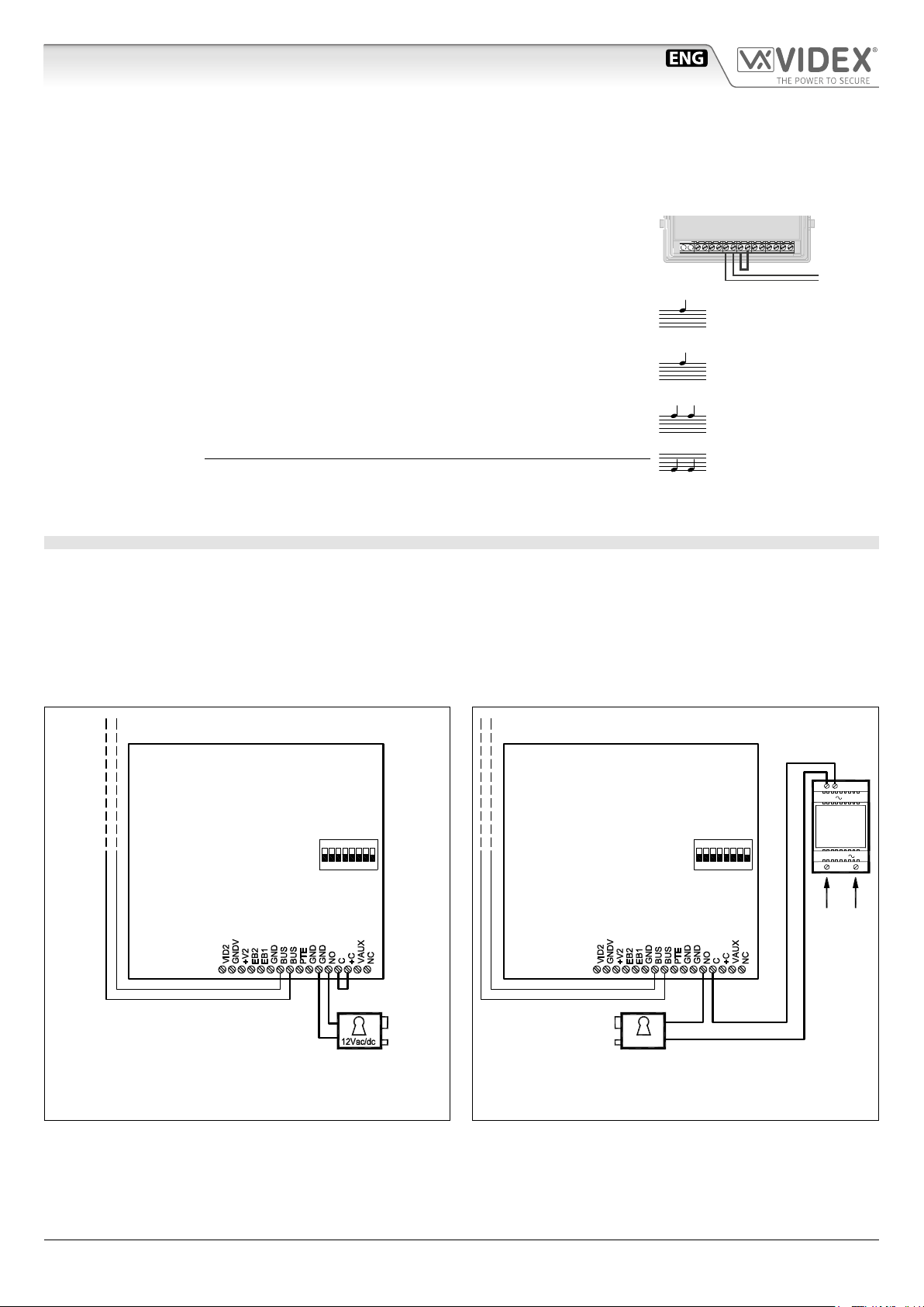
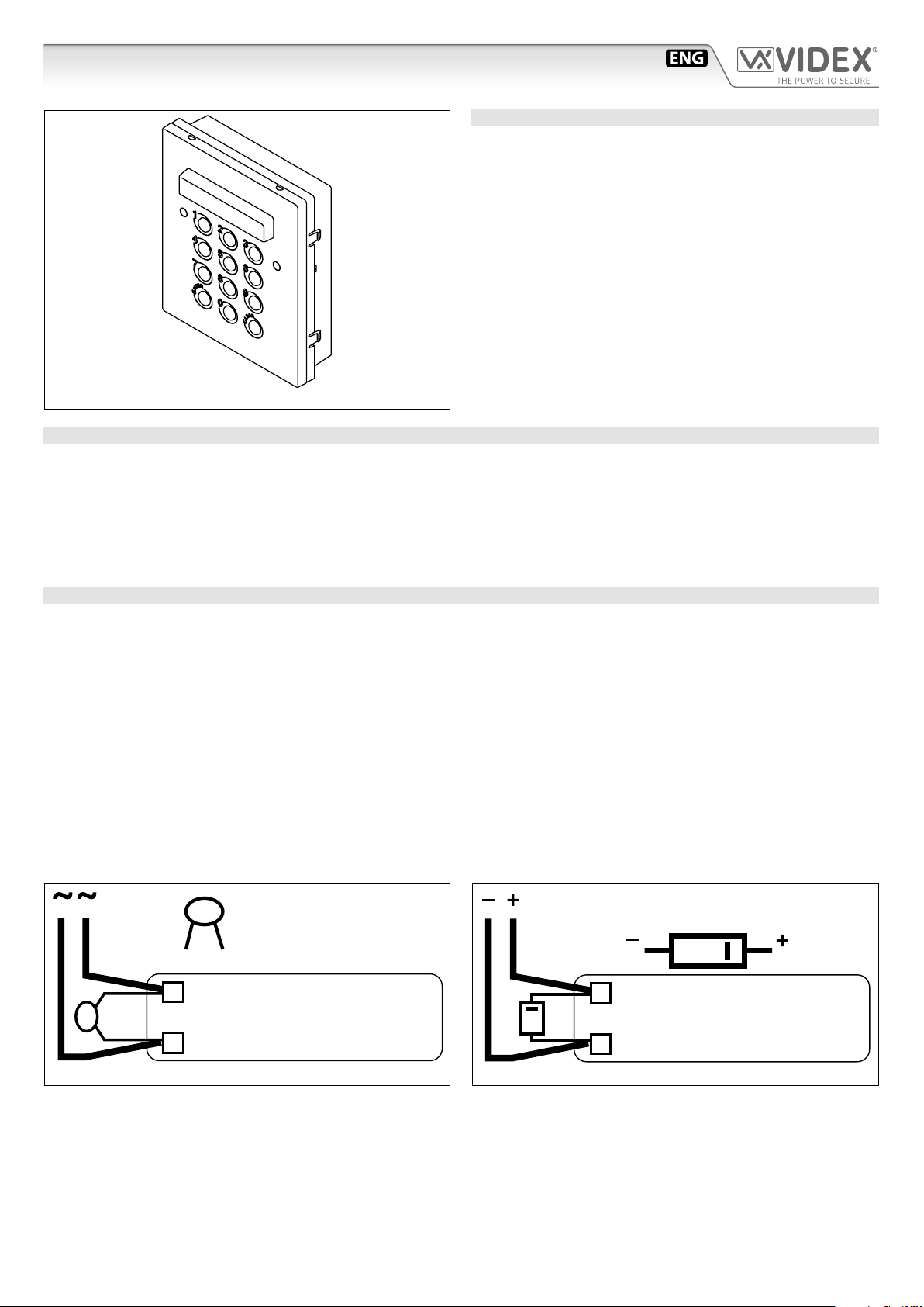
HOW TO CONNECT AN ELECTRIC LOCK
The “door-open” relay can operate either as “dry contact” or “capacitive discharge” mode.
• In “dry contact” operation mode the relay works in a traditional way, a power supply or a power source is needed to operate the
lock (12-24Vac/dc 2A max), and activation lasts according to the door opening time programmed.
• In “capacitive discharge” operation mode the relay’s contacts, when active, supply directly the lock (12Vac/dc 1A max) for a moment. You don’t need a power supply for the lock and the door opening time programmed does not aect the activation time.
A possibile deterioration of the mechanical performance of the electric lock, might cause the “capacitive discharge” to malfunction
in time. In case the electric lock is used in very dusty environments or in peculiar climate conditions, we suggest to use the “open
door” relay in “dry contact” mode.
Art.4333-1
12Vac/dc 1A Max
Fig. 3 Using capacitive discharge
Unit ID:
ON
1
2
1
4 653
87
Art.4333-1
Unit ID:
12Vac
1
13V
ART.321
ON
1
4 653
87
2
230V
230V
50/60 Hz
12Vac 1.6A Max using Art.321
24Vac/dc 2A Max using other power supplies
Fig. 4 Using separate P.S.U.
ESVK/6388 Series - Installation handbook
- 11 -
66550033-EN - V4.0 - 15/02/19
Page 12
ESVK/6388 Series “2 wire Bus” videokit
Art.4333/4333X Speaker unit module with built-in functional to digital interface
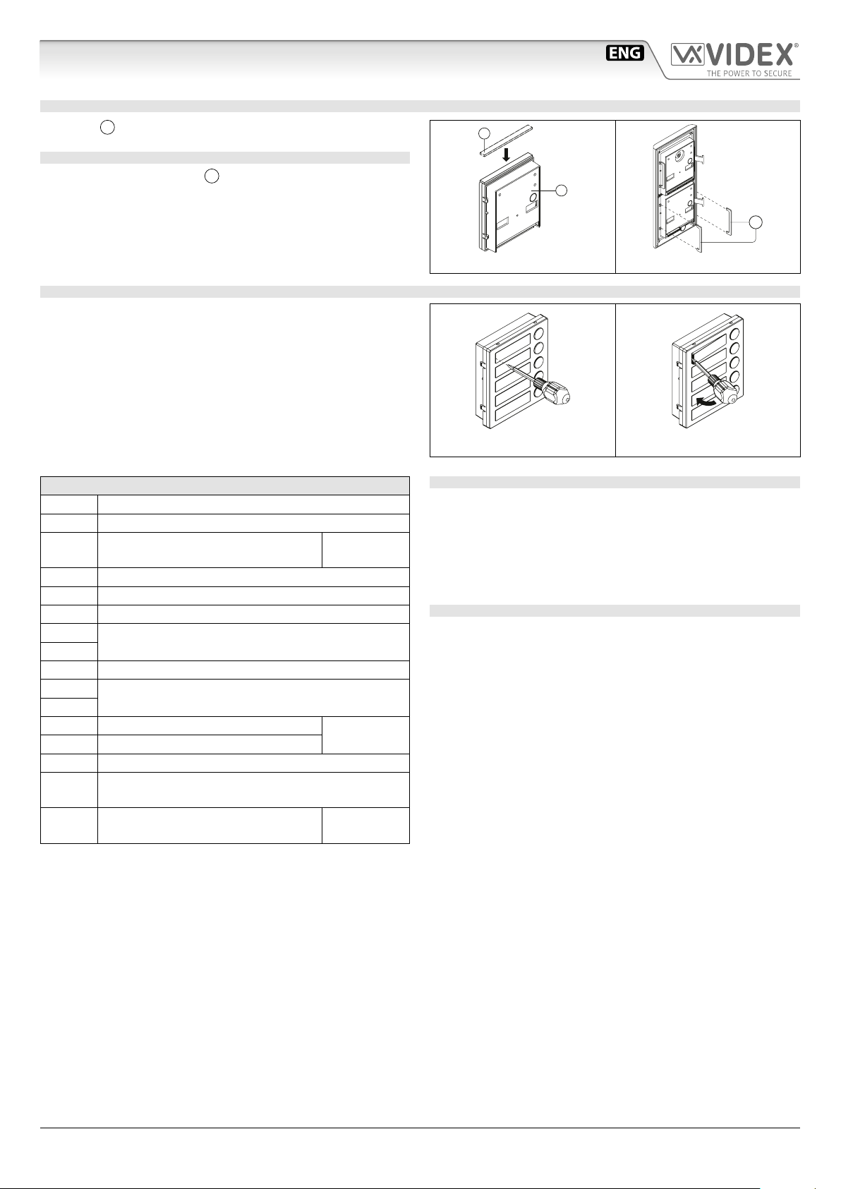
ADHESIVE GASKET PLACEMENT
Apply the Y seal as shown in Fig. 5.
ANTITAMPERING LOCKS FIXING
W
Fit the anti-tampering locks
as shown in Fig. 6.
Y
G
W
HOW TO REMOVE/INSERT THE CARD NAME HOLDER
• To avoid damage to the module front plate, mask the side that
will be in contact with the screwdriver blade;
• Insert the screwdriver (at side) into the card-holder hole as
shown in Fig. 7;
• Move the screwdriver to the left as shown in Fig. 8 to extract
the card name holder;
• Edit the card name then replace it inside the holder and ret:
insert the holder inside its housing from the left or right side
then push the other side until it clips into place.
SIGNALS ON SYSTEM CONNECTION TERMINALS
VID2 Video signal input (coax centre core)
GNDV Video signal ground (coax screen and 0V to camera)
+V2
Output to supply the external camera
if necessary
Max 12Vdc
150mA
EB2 Expansion button input 2
EB1 Expansion button input 1
GND Ground
BUS
BUS
BUS Connection terminals
PTE “Push to exit” active low input
GND
GND
NO Door open relay normally open contact
Ground
C Door open relay common contact
Max 12-24
Vac/dc 2A
+C Electric lock capacitor discharge output
VAUX
NC
35Vdc power supply input (if used, the module is
powered locally and not from the BUS)
Door open relay normally closed
contact
Max 12-24
Vac/dc 2A
Fig. 5
Fig. 7 Fig. 8
Fig. 6
CLEANING OF THE PLATE
Use a clean and soft cloth. Use moderate warm water or non-aggressive cleansers.
Do not use:
• abrasive liquids;
• chlorine-based liquids;
• metal cleaning products.
UNIT SPECIFICATION
Housing/Mounting: One 4000 Series Module / 4000 Series
Modular System
Push Buttons: Yes, from 0 to 2 call buttons depend-
ing on the model
Programming: Yes, carried out by the 8 way dip-switch
located on the rear of the module
Controls: Microphone and Loudspeaker volume
trimmers plus balance trimmer
Power Supply: Supplied by the BUS line
Power consumption: Stand-by: 50 mA
Operating: 165 mA
Working Temperature: -10 +50 °C
ESVK/6388 Series - Installation handbook
- 12 -
66550033-EN - V4.0 - 15/02/19
Page 13
ESVK/6388 Series “2 wire Bus” videokit
LOCK RELEASE BACK EMF PROTECTION
A varistor must be tted across the terminals on AC lock release
and a diode must be tted across the terminals on a DC
lock release
DIODE
Art.4800M Digital codelock module
DESCRIPTION
The module features 12 stainless steel buttons (Keys 0 - 9,
ENTER and CLEAR), 2 LED’s for progress information during
use and programming and a mirror nish stainless steel front
plate (Standard version). With three integral relays each with
common, normally open and normally closed connections and
two inputs to enable the external triggering of relays one and
two (For example, push to exit button). Key presses are signalled
both acoustically and visually while each button press has a
tactile feel. Entering the correct code followed by ENTER will
activate the relevant relay. Programming is carried out through
the same keypad following a simple programming menu. The
module can be combined with other 4000 Series modules in an
audio or video intercom system.
Fig. 1
MAIN FEATURES
• 3 C, NC, NO relay outputs (24Vac/dc – 5A max);
• 3 Programmable secret codes (one for each relay);
• Each relay can be set to be activated for a specic time (01 to 99 seconds) or to work as latch;
• Two active low inputs to command directly the relay 1 and 2;
• Programming menu guarded by a 4-8 digit programmable engineer’s code;
• Visual and Acoustic signal during operating and programming;
• Keypad illumination LEDs;
GENERAL DIRECTIONS FOR INSTALLATION
In order to achieve the best results from the schematics described it is necessary to install only original VIDEX equipment, strictly
keeping to the items indicated on each schematic and follow these General Directions for Installation:
• The system must be installed according to national rules in force, in any case the running of cables of any intercom unit must be
carried out separately from the mains;
• All multipair cables should be compliant to CW1308 specication (0.5mm twisted pair telephone cable).
• Cables for speech line and service should have a max resistance of 10 Ohm
• Lock release wires should be doubled up (Lock release wires and power supply wires should have a max resistance of 3 Ohm);
• The cable sizes above can be used for distances up to 50m. On distances above 50m the cable sizes should be increased to keep
the overall resistance of the cable below the RESISTANCES indicated above;
• Double check the connections before power up;
• Power up the system then check all functions.
(Fig.1A)
(Fig.1B) to suppress back EMF voltages. Connect the components to the lock releases as shown in gures.
VARISTOR (MOV)
12V AC
LOCK RELEASE
Fig.1A
BUZZER BACK EMF
When using intercoms with buzzer call (Art.924/926, SMART1/2, 3101/2, 3001/2 and 3021/2) add one 0.1uF (100nF) capacitor between terminals 3 and 6 on the telephone.
Fig.1B
1N4002
12V DC
LOCK RELEASE
ESVK/6388 Series - Installation handbook
- 13 -
66550033-EN - V4.0 - 15/02/19
Page 14
ESVK/6388 Series “2 wire Bus” videokit
Art.4800M Digital codelock module
BUILTIN RELAYS BACK EMF PROTECTION
The Art.4800M includes selectable back EMF protection on the relays. The jumpers marked MOV (One jumper for each relay) are used
to select the protection type. When using a fail secure lock with connections C & NO the jumper should be in the NO position. When
using a fail open lock with connections C & NC the jumper should be in the NC position and when using the codelock to trigger a gate
controller or another third party controller the jumper should be removed completely (this disables the protection on the relay).
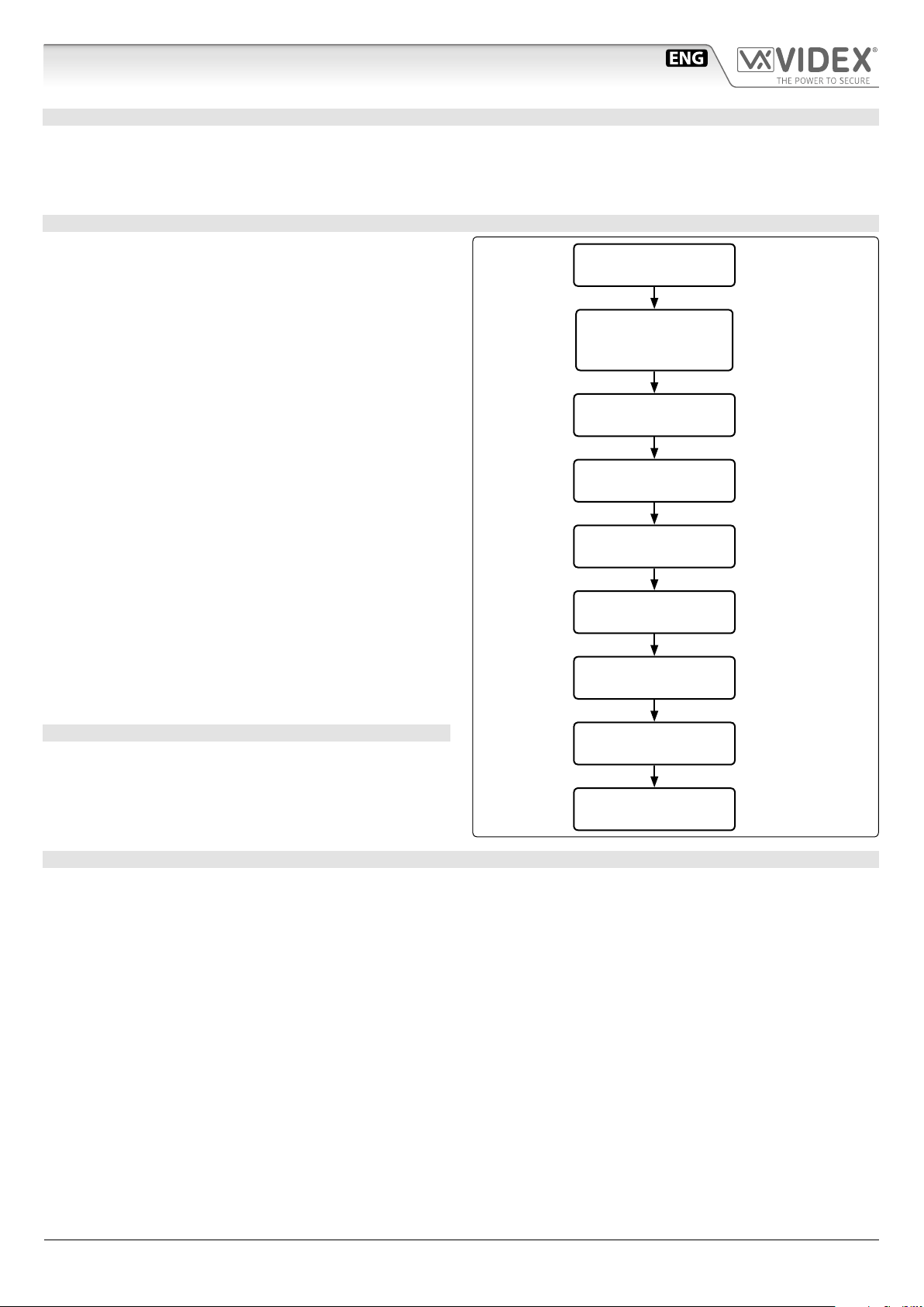
PROGRAMMING
• Enter the ENGINEER’S CODE: rst time type six times 1 (111111
factory preset) and press ENTER (The red LED will illuminate);
• Conrm ENGINEER’S CODE (typing again the same) or
type the new code (4 to 8 digits) then press ENTER (Melody). Pressing twice the ENTER button without changing the
ENGINEER’S CODE, will exit from the programming;
• Enter the code (4 to 8 digits) to enable RELAY 1 or re-enter the
existing code then press ENTER (Melody);
• Enter the RELAY 1 operation time (2 digits 01 to 99 I.E. 05=5
seconds, 00= remain open time) or re-enter the existing time
then press ENTER (Melody);
• Enter the code (4 to 8 digits) to enable RELAY 2 or re-enter the
existing code then press ENTER (Melody);
• Enter the RELAY 2 operation time (2 digits 01 to 99 I.E. 05=5
seconds, 00= remain open time) or re-enter the existing time
then press ENTER (Melody);
• Enter the code (4 to 8 digits) to enable RELAY 3 or re-enter the
existing code then press ENTER (Melody);
• Enter the RELAY 3 operation time (2 digits 01 to 99 I.E. 05=5
seconds, 00= remain open time) or re-enter the existing time
then press ENTER (Melody);
• The system is ready to use (the red LED will be o).
PROGRAMMING NOTES
• After pressing enter following a command, press ENTER a further twice to exit the programming menu.
RETURN SYSTEM TO PRESET ENGINEER’S FACTORY CODE
• Turn o power to code lock;
• Keep ENTER button pressed while turning the power back on;
• Release ENTER button;
• The engineer’s code is now set to 111111 (six times one).
Press Enter
(Red LED will
be ON)
Press Enter
(melody)
Press Enter
(melody)
Press Enter
(melody)
Press Enter
(melody)
Press Enter
(melody)
Press Enter
(melody)
Press Enter
(melody)
ENTER THE
"ENGINEER’S CODE"
CONFIRM
OR CHANGE
"ENGINEER’S CODE"
ENTER
"ACCESS 1 CODE"
ENTER
"ACCESS 1 TIME"
ENTER
"ACCESS 2 CODE"
ENTER
"ACCESS 2 TIME"
ENTER
"ACCESS 3 CODE"
ENTER
"ACCESS 3 TIME"
SYSTEM
READY TO USE
First time six times
1 “111111” factory
preset
Type again six times
“1” or the new engineer’s code 4 to 8
digits
Code to enable relay 1
4 to 8 digits
Two digits (01 to 99)
i.E. 05=5 Seconds
00= remain open
Code to enable relay 2
4 to 8 digits
Two digits (01 to 99)
i.E. 05=5 Seconds
Code to enable relay 3
4 to 8 digits
Two digits (01 to 99)
i.E. 05=5 Seconds
Red led will be o
OPERATION
• Type in the programmed code and press ENTER;
• If the code is correct, the green LED will illuminate for approx. 2 seconds and the relay relevant to the code will operate for the
programmed time;
• If a wrong code is entered, a continuous melody will sound for 4 or more seconds, according to the number of mistakes;
• To switch o any relay while operating, type in the relevant code then press the CLEAR button;
OPERATION NOTES
• To operate relays together, set the same code for each relay;
• If a wrong code is entered, the system will lock out for 5 seconds which will increase each time a wrong code is entered. The system will
operate only when the correct code is entered.
ESVK/6388 Series - Installation handbook
- 14 -
66550033-EN - V4.0 - 15/02/19
Page 15

ESVK/6388 Series “2 wire Bus” videokit
Art.4800M Digital codelock module
ADHESIVE GASKET PLACEMENT
Apply the Y seal as shown in Fig. 2.
ANTITAMPERING LOCKS FIXING
W
Fit the anti-tampering locks
as shown in Fig. 3.
Y
G
W
CONNECTION TERMINALS SIGNALS
SW2 Relay 2 command signal (active low)
SW1 Relay 1 command signal (active low)
NC3 Relay 3 normally closed contact
NO3 Relay 3 normally open contact
C3 Relay 3 common contact
NC2 Relay 2 normally closed contact
NO2 Relay 2 normally open contact
C2 Relay 2 common contact
NC1 Relay 1 normally closed contact
NO1 Relay 1 normally open contact
C1 Relay 1 common contact
12/24Vac/dc power input
+
Max
24Vac/dc
3A
Fig. 2
Fig. 3
CLEANING OF THE PLATE
Use a clean and soft cloth. Use moderate warm water or non-aggressive cleansers.
Do not use:
• abrasive liquids;
• chlorine-based liquids;
• metal cleaning products.
TECHNICAL SPECIFICATION
Power Supply: 12/24 Vac/dc – 2VA
Power Consumption: Stand-by: 20mA
Operating: 70mA
Working Temperature: -10 +50° C
ESVK/6388 Series - Installation handbook
- 15 -
66550033-EN - V4.0 - 15/02/19
Page 16

ESVK/6388 Series “2 wire Bus” videokit
4000 Series Surface and ush mounting door station installation
EXAMPLE: INSTALLING A FOUR MODULE OUTDOOR STATION
B
C
g. 1
Y
H
G
F
G
g. 4 g. 5 g. 6 g. 7
C
A
C
E
D
g. 2
W
C
H
D
C
M
g. 3
L
L
H
M
N
g. 10
g. 14
Q
P
g. 11
M
g. 8
H
H
g. 9
N
g. 12
P O
N
g. 13
g. 15
ESVK/6388 Series - Installation handbook
g. 16
- 16 -
g. 17
g. 18
66550033-EN - V4.0 - 15/02/19
Page 17

ESVK/6388 Series “2 wire Bus” videokit
4000 Series Surface and ush mounting door station installation
INSTALLING A SURFACE MOUNT DOOR STATION
1. Place the surface box against the wall (165-170cm between the top of the box and the oor level as shown in Fig.1) and mark the xing holes for
the wall plugs and the hole for the cables
In order to prevent water ingress we highly recommend using a silicon sealant between the wall and the back box C
ON THE LEFT, TOP AND RIGHT SIDES ONLY AND AROUND ALL HOLES D.
DON’T USE SILICON SEALANT ON THE BOTTOM SIDE OF THE BACK BOX (Fig.3);
2. As shown on Fig.2, drill the xing holes A, insert the wall plugs B and feed the cables E through the surface box opening D, x surface
3. Apply the
4. Before installation of the module support frame, hook the modules
5. When you have more than one support frame, hook the support frame to the surface box starting from the left. For convenience we will described
6. As shown on Fig. 9, pull back the module support frame
7. As shown in Fig. 10, open the module support frame
8. Repeat the same operations described above for the second module support frame (or for the third if available);
9. When the system has been tested and is working correctly, move back the module support frames carefully, x them to the surface box using the
C
to the wall using the screws F;
box
the two anti-tampering locks
Y
silicon sealant on top of each module as shown in Fig.4;
W
for each module (do the same for the second module support frame);
how to attach the left frame but the same must be carried out for the right frame. As shown in Fig. 7, hook the module support frame
with modules) to the surface box
M
as shown in Fig. 8;
C
required connections using the screwdriver provided
O
openings
screwdriver provided
) and adjust trimmers;
P
(torx end) and the pin machine torx screws Q (Fig. 11). Note: do not over tighten the screws more than is necessary.
E
(g.2). Observe the orientation of the box with the hinge on the left;
G
to the support frame H as shown in Fig.5 then, as shown in Fig. 6, t
H
(complete
moving the frame as suggested from pointers. Ensure that the pivots L (Fig. 7) go inside the relevant housing
H
while moving it slightly to the left as suggested by the pointers;
H
as suggested by the pointer, hook the hinge locks N to the hinges M, make the
P
(at blade end) and make the required adjustment by adjusting the settings (through
INSTALLING A FLUSH MOUNTING DOOR STATION
When ush mounting and the number of modules is greater than 3, the required back boxes need to be linked together (before embedding them
in the wall) as shown on Fig. 14, 15 and 16:
• Arrange the back boxes and remove knockouts to allow cables to be fed from one back box to the other;
• Hook the spacers to rst back box then hook the second back box to obtain the result shown on Fig. 16;
1. Protect the module support frame xing holes from dust then embed the back box into the wall (165-170cm between the top of the box and
the oor level as shown on the Fig. 1) feeding the cables
E
(Fig. 2) through a previously opened hole in the box. Observe the direction of the
box ensuring the hinge is on the left and take care that the box prole is in line with the nished wall prole;
In order to prevent water ingress we highly recommend using a silicon sealant between the module support frame
H
and the back box ON THE LEFT, TOP AND RIGHT SIDES ONLY.
DON’T USE SILICON SEALANT ON THE BOTTOM SIDE OF THE MODULE SUPPORT FRAME (Fig.12);
2. Continue from step 4 of surface mounting instructions , but at step 7 hook the hinge locks N as shown on Fig. 13.
Note: if additional holes are made in the surface box, oxidation problems may appear unless the unprotected metal is
coated with a protective paint.
NOTES
• The screwdriver’s blade has two sides, one at and one torx, to select one of them unplug the blade from the screwdriver body and plug it
into the required side.
• The example shows the use of only one back box bottom hole for wires, this is done to keep le drawings clear. Naturally the installer can use
the left hole or the right or both if required.
HOW TO REMOVE THE CARD NAME HOLDER
• To avoid damage to the module front plate, tape the side that will be in contact with the screwdriver blade;
• lnsert the screwdriver (at side) into the card-holder hole as shown in Fig. 17;
• Move the screwdriver to the left as shown in Fig. 18 to extract the card name holder;
• Edit the card name then replace it inside the holder and ret: insert the holder inside its housing from the left or right side then push the other
side until it clips into place.
ESVK/6388 Series - Installation handbook
- 17 -
66550033-EN - V4.0 - 15/02/19
Page 18

ESVK/6388 Series “2 wire Bus” videokit
Art.6388 3.5" hands free colour display digital videophone
27 mm 102 mm
BUS1
BUS2
GND
12M
H
182 mm
G
F
Fig. 1 Front
Fig. 2 Back
I
GNDVAC
NO
ON
1
2
3
4
ON
1
2
3
4
5
6 7 8
COLOUR CONTR
BC
-DOL
+DOL
S3
DPSW2
DPSW1
R01A
GND ALBAL
E
D
A
DESCRIPTION
An intelligent hands free videophone using 3.5” full colour active matrix LCD monitor for VX2300.
Including 4 buttons: Service, Privacy/Bus relay activation/Camera switch/Call reject, Door-open/Intercommunicating call, Answer/OFF/Camera recall/Push to talk plus 3 LED’s for visual indication of all functions.
Adjustments & programmable options: call tone volume on 3
levels (low, medium, high), picture hue, brightness and contrast, call tone melody, number of rings, privacy duration and
address. Also includes a local bell function. The Art.6388 is surface mount.
PUSH BUTTONS
Service push button
When pressed it links internally the terminals C and NO on the connection terminals.
Privacy ON-OFF push button
To enable the function press this button when the videophone is in stand-by. The service is automatically disabled when the
programmed time expires (the privacy duration time can be programmed) or manually by pressing again the button.
Activate bus relay board Art.2305 push button
To activate a bus relay, during a conversation, press this button quickly as many times as the address value of the relay.
Camera switch push button
If the door station uses the Art.4303N plus the Art.4330N, pressing this button during a conversation switches the video signal
coming from the camera module to the video signal coming from the camera module input for external camera. During the
conversation, press and keep pressed the button until the camera switches. Repeat the operation to switch back to main camera.
Call Reject button
During an incoming call, press this button to reject the call. The visitor doesn’t receive any warning of the call rejected.
Door open push button
Press this button to open the door when you are in conversation or you are receiving a call.
Intercommunication push button
For an intercommunicating call, press as many times as the extension or address value to call (see SW2 Intercommunication
Settings).
LEGEND
A
Speech volume control
B
Call tone volume switch
C
Brightness control
D
Contrast adjustment trimmer
E
Hue adjustment trimmer
F
4 Way dip switch bank
G
8 Way dip switch bank
H
Bus termination switch
I
Connection terminals
ESVK/6388 Series - Installation handbook
- 18 -
66550033-EN - V4.0 - 15/02/19
Page 19

ESVK/6388 Series “2 wire Bus” videokit
Art.6388 3.5" hands free colour display digital videophone
PUSH BUTTONS
Answerpush button
On an incoming call, operation of this button allows the user to answer and converse with the visitor. The relevant LED will
illuminate.
Switch o button
With the system switched on (monitor on), momentary operation of the button will switch the video monitor o.
The videomonitor will also automatically switch o after a time delay if the button is not pressed. The relevant LED will switch o.
Camera Recall push button
Press as many times as the DEVICE N. of the door station to switch on.
Simplex button
Pressing and holding the button for more than 3 seconds will switch the videomonitor into SIMPLEX speech mode. Press
and hold the button to speak to the caller (
If the button is not pressed for 10 seconds the videomonitor will switch o. The videomonitor will revert to duplex speech
when another call is made.
LED will ash rapidly), release the button to listen ( LED will ash slowly).
LEDS
Privacy on LED
It illuminates when the privacy service is enabled.
Generic use LED
It is controlled from the terminals +DOL and –DOL. Normally used to signal the door status (open or closed).
ON LED
It illuminates when the videophone is switched ON.
PROGRAMMING
The videophone setup consists of the following settings:
• Number of rings;
• Melody selection;
• Privacy duration;
• Unit address (1..127, switches 1 to 7 of SW1);
• Bus Termination (open or close, S3 switch);
• Intercommunication mode (between apartments or within apartment, switch 1 of SW2);
• Extension address (1..4, switches 2,3 of SW2);
• Slave mode (switch 4 of SW2).
The programming of the number of rings, melody and privacy duration are carried out through the videophone push buttons, all
other settings are carried out on the two dip-switch banks (SW1 and SW2) on the rear side of the video monitor (all the settings can
be done without opening the videophone).
It is necessary to remove temporary the power supply after making any programming changes.
NUMBER OF RINGS, MELODY SELECTION AND PRIVACY DURATION
All programming options are available only when the system is in stand-by.
CONTROLS
COLOUR
CONTR
S3
Speech volume control
(sliding wheel).
Call tone volume control
(3 levels).
Brightness control
(sliding wheel).
Colour intensity control trimmer
(rotate left to increase or right to decrease).
Contrast control trimmer*
(rotate left to increase or right to decrease).
*Not available in some LCD versions.
Bus termination switch
(lower position = BUS termination active, upper position = BUS termination disabled).
NUMBER OF RINGS.
• Keep pressed the
• Press the
the button is pressed.
• Once the required number of rings is reached, wait approx 5 seconds for the two LED’s to switch o. The new value is stored.
MELODY SELECTION
• Keep pressed the
• Press the button and keep it pressed to listen the next melody. Repeat the operation until the required melody is found.
• Once the required melody is found, wait approx 5 seconds for the two LED’s to switch o. The new melody is set.
ESVK/6388 Series - Installation handbook
button for the number of times corresponding to the required number of rings to set. A beep conrms each time
button until the two LEDs and switch on.
button until the two LEDs and switch on. The unit emits the current selected melody.
- 19 -
66550033-EN - V4.0 - 15/02/19
Page 20

ESVK/6388 Series “2 wire Bus” videokit
C
NO
-DOL
+DOL
GND A
LB
S3
C
NO
-DOL
+DOL
GND A
LB
S3
Art.6388 3.5" hands free colour display digital videophone
PRIVACY DURATION
• Keep pressed the
• Press the button for the number of times corresponding to the required privacy duration to set. Each time the button is
pressed, the duration is increased by 15 minutes: i.e. to set 2 hours, press the button 8 times.
• Once the required privacy time is reached, wait approx 5 seconds for the two LED’s to switch o. The new duration is set.
VIDEOPHONE ADDRESS SW1.1..7
The table below shows how to set the address of the videophone. Considering that ON = 1 and OFF = 0, multiply
each digit for the relevant decimal weight then sum values obtained to get the address: E.g. as highlighted in
the table OFF, ON, OFF, OFF, ON, OFF, ON in binary is equal to 0100101 then multiplying each digit for the relevant decimal weight you obtain the address that is 37.
7 6 5 4 3 2 1 64 32 16 8 4 2 1
OFF OFF OFF OFF OFF OFF ON 0 0 0 0 0 0 1 1
OFF OFF OFF OFF OFF ON OFF 0 0 0 0 0 1 0 2
OFF OFF OFF OFF OFF ON ON 0 0 0 0 0 1 1 3
OFF OFF OFF OFF ON OFF OFF 0 0 0 0 1 0 0 4
OFF ON OFF OFF ON OFF ON 0 1 0 0 1 0 1 37
ON ON ON ON ON ON ON 1 1 1 1 1 1 1 127
Note: The maximum number of units allowed is 100 but the address of each unit can be a value between 1 and 127.
VIDEOPHONE END OF LINE TERMIANTION S3
Looking at the videophone from the rear:
button until the two LEDs and are switched on.
ON
1 2 3 4 5 6 7 8
SW1.1..7
SWITCHES STATUS BINARY CODE DECIMAL WEIGHT ADDRESS
Move the switch S3 to the lower position
to disable the bus termination.
Move the switch S31 to the upper position to enable the bus termination.
In case of more units (intercoms, videophones or video monitors) in a parallel connection (bus wires are connected to the terminals
of the rst unit then from this to the second and so on up to 4 units max) the BUS termination must be enabled only for the last unit
in the chain while on all other units it must be set to disabled.
INTERCOMMUNICATION MODE SW2.1
This switch establishes the intercommunication mode: in OFF position (default) intercommunication is between units in
the same apartment (same addresses but dierent extension); in ON position the intercommunication is between units
in dierent apartments (dierent addresses).
On installations where there are more than one intercom/videophone in the same apartment and intercommunication between dierent apartments is required, only one intercom/videophone may be set with this function (SW2.1=ON,
SW2.2=OFF, SW2.3=OFF). The other intercom/videophones in the apartment must be set for local intercommunication with
extension addresses “2-4” (slaves). From the intercom/videophone set for intercommunication with other apartments it
will not be possible to intercommunicate within the apartment but slave extensions 2-4 will be able to intercommunicate
with each other within the apartment.
EXTENSION NO SW.2..3
If the intercommunication between apartments is enabled (switch 1 of
leave these two switches in default position (both to OFF). Otherwise, if the intercommunication is between the same apartment (switch 1 of
the extension addresses starting always from 1. During the external call, all video
monitors in the same at will ring but the video will be shown only from the videophone with extension address 1.
SW2
= OFF), set
SW2
= ON)
ON
1 2 3 4
SW2.2..3
2 3 EXTENSION NO.
OFF OFF 1 (default, master)
ON OFF 2 (slave)
OFF ON 3 (slave)
ON ON 4 (slave)
ON
1 2 3 4
SW2.1
ESVK/6388 Series - Installation handbook
- 20 -
66550033-EN - V4.0 - 15/02/19
Page 21

ESVK/6388 Series “2 wire Bus” videokit
Art.6388 3.5" colour display videophone
SLAVE MODE SW2.4
This set up concerns the answering mode of the video monitor when there is more than one unit (max 4) in the same
apartment. OFF (default) = during a call, only the video monitor with extension 1 (master) will show the video. ON = the
video monitor will be switched on independently of the extension address: in this case the video monitor must be supplied locally using a power supply Art.2321 and connecting respectively BUS+ to terminal +VAUX and BUS– to terminal
GND on the connection terminals (the local power supply is required for each black & white slave videophone or starting from the
third slave videophone when they are all colour videophones).
If you set for one slave videophone, you must set ON the same switch also for the relevant master videophone.
ON
1 2 3 4
SW2.4
CONNECTION TERMINALS SIGNALS
BUS1 Bus input
BUS2 Bus input
GND Ground
+12Vdc power supply input (Art.323/12 or Art.AMR2-
12) for version with Memory Board option or auxiliary
12M
power supply input (to be used when two or more slave
monitors are ringing together with the switch 4 of SW3
is set to ON)
GND Ground
+30Vdc power supply input (Art. 2321) to be used
VA
when two or more slave monitors are ringing together with the switch 4 of SW3 set to ON
Dry contact. Internally linked to NO
C
when the
Dry contact. Internally linked to C
NO
when the
button is pressed.
button is pressed.
DOL Auxiliary LED power supply input (ground)
+DOL Auxiliary LED power supply input (+12Vdc)
GND A
Ground output for use in combination with AL & LB
active low inputs
LB Local bell input (active low)
AL Alarm input (not implemented yet)
TECHNICAL SPECIFICATION
Housing/Mounting: 6300 Series Videophones
surface mount
Push buttons: Yes, 4
Programming: Yes, carried out by the buttons and
the dip-switches located on the rear
of the videophone
Controls: Call tone volume, picture hue,
brightness and contrast
Power Supply: Supplied by the BUS line
Power consumption: Stand-by: 0.2mA
Operating: 115mA
Working Temperature: -10 +50 °C
Max 35Vdc,
50mA
MEMORY BOARD
This device is also available in the version with memory board (Art.6388/VM).
If you have that version, please refer to the “6200, 6300, 6400 and 6700 Series Memory Board” user manual (in
English and Italian) for installation and use.
The manual is available for download: click/tap or scan the QR code.
ESVK/6388 Series - Installation handbook
- 21 -
66550033-EN - V4.0 - 15/02/19
Page 22

ESVK/6388 Series “2 wire Bus” videokit
1
2
6300 Series Wall mounting instructions
A
2
A
135cm
Fig. 1
E
C
D
F
D
Fig. 4 Fig. 5 Fig. 6
G
C
G
Fig. 2
B
B
Fig. 3
1
Fig. 7
1. In order to install the videophone, it is necessary to remove the cover, which contains all the electronics, from the base:
insert a 5.5mm at screw driver into the clip A then rotate clockwise until you listen a “CLICK!”.
Repeat the same operation with the other clip as shown in Fig. 1.
2. Pull outwards the upper part of the cover as shown in Fig. 2. Don’t pull the cover straight.
3. Put the base of the unit on the wall at approx 135cm from the nished oor (Fig. 3) to match the points for the xing holes B
(Fig. 4) remembering that the wires E (Fig. 4) must be fed through the large hole F (Fig. 4). If you use the ush mounting box
503, embed it into the wall vertically at approx. 140cm from the nished oor and the base.
4. Following Fig. 4, make the holes B, insert the wall plugs C and x the base with the screws D feeding the wires E through
the hole F. If you have used the box 503, x the base to the wall through the holes G using the screws D.
5. As shown in Fig. 5, connect the wires to the removable terminals following the provided installation diagram. Connect the terminal
blocks to the electronics contained in the cover as shown in Fig. 6. Test system before closing.
Contrast and hue trimmers can be adjusted only if the videophone is open. To activate the display and see changes use the
“Camera Recall” function by pressing
Note: while testing the system, it is advisable to hold the cover with your hand.
6. Once testing is complete and all the necessary adjustments are made, close the unit as shown in Fig. 7: rst hook in the bottom
and then the upper part until you hear a “CLICK!”.
button.
ESVK/6388 Series - Installation handbook
- 22 -
66550033-EN - V4.0 - 15/02/19
Page 23

ESVK/6388 Series “2 wire Bus” videokit
Art.2321-2321/P Power supplies for VX2300
Art.2321
105
BUS
+
230V
0V
157,5
Fig. 1
DESCRIPTION
These two power supplies are specically designed for the
VX2300 digital system. The Art. 2321 can be used for systems
with 1 entrance up to 20 users while the Art.2321/P is for systems with more than 1 entrance and up to 100 users.
CONNECTION TO MAINS AND POWER SUPPLY MOUNTING INSTRUCTIONS
This equipment is not suitable for use in locations where children are likely to be present.
The system must be installed according to national rules in force, in particular we recommend to:
• Connect the system to the mains through an all-pole circuit breaker which shall have contact separation of at least 3mm in each
pole and shall disconnect all poles simultaneously;
• The all-pole circuit breaker shall be placed for easy access and the switch shall remain readily operable.
_
65
Fig. 2
CONNECTION TERMINALS AND JUMPERS
0
~230V
BUS +
BUS –
BUS +
BUS –
V1 Jumper to adjust the output voltage (only Art.2321/P).
V2
V3
Mains input
BUS terminals
BUS terminals (only Art.2321/P)
V1=Low, V2=Medium, V3=Maximum. Set to maximum
(V3) when the unit is used together with Art. 2301N,
otherwise leave in a low or medium position.
POWER SUPPLY INSTALLATION
• Remove the terminal side covers by unscrewing the retaining screws;
• Fix the power supply to a DIN bar or directly to the wall using two expansion type screws;
• Switch o the mains using the circuit breaker mentioned above and then make the connections as shown on the installation diagrams;
• Check the connections and secure the wires into the terminals;
• Replace the terminal covers and x them using the relevant screws;
• When all connections are made, restore the mains.
SPECIFICATION
Housing/Mounting: 9 Module A Type DIN box (Art.2321) –
12 Module A Type DIN box (Art.2321/P)
/ DIN Bar or directly to the wall
Push Buttons: N/A
Programming: N/A
Controls: Voltage amplication (3 levels)
Power Supply: 230 Vac
Working Temperature: -10 +50°C
ART.2321 ELECTRICAL DATA
Mains voltage: 230 Vac ~ 50/60 Hz
Output voltage: 32 Vdc 0.8 A
Internal fuse: -
ART.2321/P ELECTRICAL DATA
Mains voltage: 230 Vac ~ 50/60 Hz
Output voltage: 35 Vdc 1.5 A
Internal fuse: T 350 mA L 250
ESVK/6388 Series - Installation handbook
- 23 -
66550033-EN - V4.0 - 15/02/19
Page 24

ESVK/6388 Series “2 wire Bus” videokit
Art.2322 Power supply converter from BUS line to 12 Vdc
BUS
Art.2322
+
12V
-
Fig. 1
DESCRITPION
When this unit is connected to the BUS line it generates a +12Vdc – 100mA power source. This unit can be used to supply peripherals such as the Art.4800 or Art.4800M without the need for an additional power supply.
Please note: The peripherals must not require more than 100mA.
CONNECTION TERMINALS
BUS
BUS
12V+
12V– (0V)
TECHNICAL SPECIFICATION
Housing/Mounting: Plastic box 50x60x20mm / direct wall mounting
Push buttons: N/A
Programming: N/A
Controls: N/A
Power supply: Supplied by the BUS line
Working temperature: -10° +50° C
BUS line inputs
12Vdc – 100mA output
Fig. 2
ESVK/6388 Series - Installation handbook
- 24 -
66550033-EN - V4.0 - 15/02/19
Page 25

ESVK/6388 Series “2 wire Bus” videokit
1,5KOhm 1W
Art.125 Call expansion module
DESCRITPION
This module must be used in combination with speaker units Art.4333 with rmware release 2.0 or higher. The module, in combination with standard 4000 series button expansion modules (Art.4842, Art.4843, Art.4844 and Art.4845), allows to add up to
5 call buttons to the call buttons built-in the speaker unit to reach a maximum of 7 call buttons. To supply the LED of the button
expansion modules make the connection as shown in gure 1. From Art.4333 rmware version 2.3 or later, the switch n.6 sets the
addressing order of the buttons so you can sort them as shown above.
Please follow the directions in the diagram to supply the push buttons modules.
ON
87
653
4
21
VAUX
C
GND
GND
GND
BUS
EB1
+C
NO
BUS
PTE
NC
Push to
Exit
Art.4333-2
VID2
GNDV
+V2
EB2
2C
3C4C5C
1C
Art.4845
Art.125
4
2
2C
+
-
1
1C
5C
3C4C3
5
Fig. 1 New plate design, 1 button expansion module
Switch 7 = OFF
2
1
7
6
5
EB1
4
3
Switch 7 = OFF
Switch 7 = ON
12
11
5
Connect to “EB1”
terminalof Art.4333
4
3
EB1
2
1
RED
Connect to “1C” terminal of
Art.4842, Art.4843, Art.4844 or Art.4845
Connect to terminal “1” of the button expansion module
Connect to terminal “2” of the button expansion module
Connect to terminal “3” of the button expansion module
Connect to terminal “4” of the button expansion module
Connect to terminal “5” of the button expansion module
Switch 7 = ON
Connect to “GND”
terminalof Art.4333
BLACK
ON
653
87
4
Art.4333-2
Push to
Exit
Art.4845
1,0KOhm 1W
+
-
Art.4845
VID2
GNDV
+V2
2C
3C4C5C
1C
4
2
2C
3C4C3
1C
1
2C
3C4C5C
1C
21
VAUX
C
GND
GND
GND
EB2
EB1
+C
BUS
BUS
PTE
NO
NC
Art.125
5C
5
Art.125
4
2
2C
5C
5
3C4C3
+
-
1C
1
Fig. 2 New plate design, 2 buttons expansion modules
2
1
12
11
10
EB2
9
8
7
6
5
EB1
4
3
12
11
10
9
8
EB2
Connect to “GND”
terminalof Art.4333
7
6
5
4
3
EB1
2
1
Connect to “EB1”
or “EB2” terminal
of Art.4333
RED
BLACK
Connect to “1C” terminal of
Art.4842, Art.4843, Art.4844 or Art.4845
Connect to terminal “1” of the button expansion module
Connect to terminal “2” of the button expansion module
Connect to terminal “3” of the button expansion module
Connect to terminal “4” of the button expansion module
Connect to terminal “5” of the button expansion module
ESVK/6388 Series - Installation handbook
- 25 -
66550033-EN - V4.0 - 15/02/19
Page 26

ESVK/6388 Series “2 wire Bus” videokit
5
3
2
1
O
4
5
3
2
1
O
Art.125 Call expansion module
Connect to “PTE” terminal of Art.4333
Red
Connect to “1C” terminal of Art.4842,
Art.4843, Art.4844 or Art.4845
Connect to terminal “1” of the button expansion module
Connect to terminal “2” of the button expansion module
Connect to terminal “3” of the button expansion module
Connect to terminal “4” of the button expansion module
Connect to terminal “5” of the button expansion module
ON
N
Switch 6 = OFF
Art.4333 Rev. xx
653
4
4
1
2
Connect to “GND” terminal ofArt.4333
Black
ON
4
1
Art.4333-1
4C
2C
5C
3C
1C
Art.4845
1,5KOhm 1W
ON
N
1
2
2
2C
+
-
1
1C
Switch 6 = ON
Art.4333 Rev. 2.3 or later
653
4
3C4C3
2
GND
GND
BUS
BUS
PTE
4
5
5C
BALANCE
1
653
VAUX
C
+C
NO
NC
1
2
7
6
5
4
3
1
7
6
5
4
3
Fig. 3 Old plate design
TECHNICAL SPECIFICATION
Housing/Mounting: 5 resistors module / x to button expansion module
Push buttons: N/A
Programming: N/A
Controls: N/A
Power supply: N/A
Working temperature: -10° +50° C
6
7
5
4
3
2
1
6
5
4
3
2
1
ESVK/6388 Series - Installation handbook
- 26 -
66550033-EN - V4.0 - 15/02/19
Page 27

GND
esvk-63h-001.dw
g
BUS1
BUS2
ART.6388
GND
+12VM
Term. OFF
Term. ON
Local Bell
ON
C
NO
-DOL
+VAUX
+DOL
S3
1
2
LB
AL
43876
5
AL-LB GND
ON
1
2
43
Extension N.
Videophone:
1
1
Art.2321
BUS
N.B.
Dopo ogni cambiamento
nella programmazione del
posto esterno, del
videocitofono o del relè, è
necessario togliere
l'alimentazione al sistema
e ripristinarla affinchè le
variazioni vengano
recepite dai rispettivi
dispositivi.
After each change on the
programming of the door
station, videophone or any
other device connected to
the system it is necessary
to restart the system
(power off then power on).
Titolo:
Videx Electronics S.p.A.
Via del Lavoro 1, 63846 Monte Giberto (FM)
Phone: +39 0734 631669 - Fax +39 0734 631669
www.videx.it - info@videx.it
Notes:
Note:
Unit ID:
Art.4333-1
1
ON
653
87
4
21
1
SE
Push to Exit
12Vac
Data creazione:Title:
17/02/2017
Data modifica:
20/02/2017
Autore:
Roberto Gambini
Cod.File:
Foglio
/11
- 27 -
66550033-EN - V4.0 - 15/02/19
Page 28

Local Bell
esvk-63h-002.dw
g
Local Bell
Local Bell
GND
BUS2
GND
+12VM
Term. OFF
Term. ON
BUS1
ART.6388
Extension N.
Videophone:
ON
C
NO
-DOL
+VAUX
+DOL
S3
1
2
LB
AL
43876
5
AL-LB GND
ON
1
2
43
GND
BUS1
BUS2
GND
+12VM
+VAUX
Term. OFF
Term. ON
C
NO
LB
-DOL
S3
AL
+DOL
AL-LB GND
ON
21
3876
4
5
ON
21
3
4
ART.6388
1
2
Extension N.
Videophone:
1
1
N.B.
Dopo ogni cambiamento
nella programmazione del
posto esterno, del
videocitofono o del relè, è
necessario togliere
l'alimentazione al sistema
e ripristinarla affinchè le
variazioni vengano
recepite dai rispettivi
dispositivi.
After each change on the
programming of the door
station, videophone or any
other device connected to
the system it is necessary
to restart the system
(power off then power on).
Titolo:
Videx Electronics S.p.A.
Via del Lavoro 1, 63846 Monte Giberto (FM)
Phone: +39 0734 631669 - Fax +39 0734 631669
www.videx.it - info@videx.it
Notes:
Note:
Art.2321
BUS
ON
4
21
1
653
87
SE
12Vac
Data creazione:Title:
17/02/2017
Data modifica:
20/06/2018
Autore:
Roberto Gambini
Cod.File:
Foglio
/11
Unit ID:
Art.4333-2
2
1
Push to Exit
- 28 -
66550033-EN - V4.0 - 15/02/19
Page 29

GND
esvk-63h-003.dw
g
BUS1
BUS2
ART.6388
GND
+12VM
Term. OFF
Term. ON
Local Bell
ON
C
NO
-DOL
+VAUX
+DOL
S3
1
2
LB
AL
43876
5
AL-LB GND
ON
1
2
43
N.B.
Dopo ogni
cambiamento nella
programmazione del
posto esterno, del
videocitofono o del
relè, è necessario
togliere
l'alimentazione al
sistema e ripristinarla
affinchè le variazioni
vengano recepite dai
rispettivi dispositivi.
After each change on
the programming of
the door station,
videophone or any
other device
connected to the
system it is necessary
to restart the system
(power off then power
on).
Titolo:
Videx Electronics S.p.A.
Via del Lavoro 1, 63846 Monte Giberto (FM)
Phone: +39 0734 631669 - Fax +39 0734 631669
www.videx.it - info@videx.it
Notes:
Note:
Extension N.
Videophone:
Art.2322
1
1
Art.2321
BUS
BUS
+
12V
-
Unit ID:
Art.4333-1
Push
to Exit
1
MOV
Art.4800
ON
4
21
1
653
87
SE
12Vac
Data creazione:Title:
17/02/2017
Data modifica:
20/02/2017
Autore:
Roberto Gambini
Cod.File:
Foglio
/11
- 29 -
66550033-EN - V4.0 - 15/02/19
Page 30

Local BellLocal BellLocal Bell
esvk-63h-004.dw
g
GND
BUS2
GND
+12VM
Term. OFF
Term. ON
BUS1
ART.6388
Extension N.
Videophone:
ON
C
NO
-DOL
+VAUX
+DOL
S3
1
2
LB
AL
43876
5
AL-LB GND
ON
1
2
43
GND
BUS1
BUS2
GND
+12VM
+VAUX
Term. OFF
Term. ON
C
NO
LB
-DOL
S3
AL
+DOL
AL-LB GND
ON
21
3876
4
5
ON
21
3
4
ART.6388
1
2
Extension N.
Videophone:
1
1
Art.2321
BUS
N.B.
Dopo ogni cambiamento
nella programmazione del
posto esterno, del
videocitofono o del relè, è
necessario togliere
l'alimentazione al sistema
e ripristinarla affinchè le
variazioni vengano
recepite dai rispettivi
dispositivi.
After each change on the
programming of the door
station, videophone or any
other device connected to
the system it is necessary
to restart the system
(power off then power on).
Titolo:
Videx Electronics S.p.A.
Via del Lavoro 1, 63846 Monte Giberto (FM)
Phone: +39 0734 631669 - Fax +39 0734 631669
www.videx.it - info@videx.it
Notes:
Note:
Art.2322
Unit ID:
BUS
+
12V
-
Art.4333-2
1
ON
653
87
4
21
SE
2
Push
to Exit
12Vac
1
MOV
Art.4800
Data creazione:Title:
17/02/2017
Data modifica:
20/02/2017
Autore:
Roberto Gambini
Cod.File:
Foglio
/11
- 30 -
66550033-EN - V4.0 - 15/02/19
Page 31

Local Bell
esvk-63h-005.dw
g
GND
BUS1
GND
BUS2
+12VM
Term. OFF
Term. ON
ART.6388
Extension N.
Videophone:
C
NO
+VAUX
LB
-DOL
S3
AL
+DOL
AL-LB GND
ON
21
3876
4
5
ON
21
3
4
Art.2305
VIDEX
Art.3183
GND
BUS
BUS
S1
LB
AL
1
1
Extension N.12
Phone No.
Service 2 Service 1
Art.2305
Art.2321
External
150mA MAX
N.B.
Dopo ogni cambiamento nella
programmazione del posto
esterno, del videocitofono o del
relè, è necessario togliere
l'alimentazione al sistema e
ripristinarla affinchè le variazioni
vengano recepite dai rispettivi
dispositivi.
After each change on the
programming of the door station,
videophone or any other device
connected to the system it is
necessary to restart the system
(power off then power on).
Titolo:
Videx Electronics S.p.A.
Via del Lavoro 1, 63846 Monte Giberto (FM)
Phone: +39 0734 631669 - Fax +39 0734 631669
www.videx.it - info@videx.it
Notes:
Note:
Camera
12Vdc
BUS
Unit ID:
Art.4333-1
1
ON
653
87
4
21
1
Push
to Exit
12Vac
Data creazione:Title:
17/02/2017
Data modifica:
20/02/2017
Autore:
Roberto Gambini
Cod.File:
Foglio
/11
- 31 -
66550033-EN - V4.0 - 15/02/19
Page 32

1/2
esvk-63h-006.dw
g
Art.2321
BUS
N.B.
Dopo ogni cambiamento
nella programmazione del
posto esterno, del
videocitofono o del relè, è
necessario togliere
l'alimentazione al sistema
e ripristinarla affinchè le
variazioni vengano
recepite dai rispettivi
dispositivi.
After each change on the
programming of the door
station, videophone or any
other device connected to
the system it is necessary
to restart the system
(power off then power on).
Titolo:
Videx Electronics S.p.A.
Via del Lavoro 1, 63846 Monte Giberto (FM)
Phone: +39 0734 631669 - Fax +39 0734 631669
www.videx.it - info@videx.it
Notes:
Note:
12
11
10
1
ON
653
87
4
21
VAUX
C
GND
GND
+C
NO
NC
12Vdc
Push to
Exit
Art.4333-2
Art.4845
2C
3C4C5C
Unit ID:
VID2
GNDV
GND
+V2
BUS
BUS
PTE
EB2
EB1
1C
Art.125
9
+
-
1C
1
4
2
2C
3C4C3
5
5C
8
7
1,0KOhm 1W
6
2C
5
4
3C4C5C
1C
Art.4845
3
2
1
+
-
1C
1
4
2
2C
3C4C3
5C
Art.125
5
Data creazione:Title:
20/02/2017
Data modifica:
20/06/2018
Autore:
Roberto Gambini
Cod.File:
Foglio
/11
- 32 -
66550033-EN - V4.0 - 15/02/19
Page 33

2/2
Local BellLocal BellLocal Bell
GND
BUS2
GND
+12VM
Term. OFF
Term. ON
BUS1
ART.6388
Extension N.
Videophone:
ON
C
NO
-DOL
+VAUX
+DOL
S3
1
2
LB
AL
43876
5
AL-LB GND
ON
1
2
GND
BUS1
BUS2
GND
+12VM
+VAUX
Term. OFF
Term. ON
C
NO
LB
-DOL
S3
AL
+DOL
AL-LB GND
43
ON
1
2
43876
5
ON
1
2
43
ART.6388
1
3
BUS OUT 2 BUS OUT 3 BUS OUT 4
BUS OUT 1
Close
Close
Close
Open
Open
S1 S2 S3 S4
BUS LINE
TERMINATION
AMP
Close
Open
Close
Open
Open
AMPLIFICATION
H
ON
M
OFF
L
BUS
BUS
OUT
IN
Extension N.
Videophone:
1
4
Art.317N
GND
BUS2
GND
+12VM
Term. OFF
Term. ON
BUS1
ART.6388
Extension N.
Videophone:
Local BellLocal BellLocal Bell
ON
C
NO
-DOL
+VAUX
+DOL
S3
21
LB
AL
3876
4
5
AL-LB GND
GND
BUS1
BUS2
ON
21
3
4
GND
+12VM
+VAUX
Term. OFF
Term. ON
C
NO
LB
-DOL
S3
AL
+DOL
AL-LB GND
ON
21
3876
4
5
ON
21
3
4
ART.6388
1
1
- 33 -
Extension N.
Videophone:
1
2
66550033-EN - V4.0 - 15/02/19
Page 34

1/2
esvk-63h-007.dw
g
V1V2V3
N.B.
Dopo ogni cambiamento nella programmazione
del posto esterno, del videocitofono o del relè, è
necessario togliere l'alimentazione al sistema e
ripristinarla affinchè le variazioni vengano
recepite dai rispettivi dispositivi.
After each change on the programming of the
door station, videophone or any other device
connected to the system it is necessary to
restart the system (power off then power on).
IN3
IN2 IN1
IN4
Art.4333-0
Art.2321/P
230V
0V
Unit ID:
ON
653
4
21
Art.2301N
BUS
BUS
+_+
_
1
87
3
2
1
PS2 PS1
Art.4333-0
AUXBUS
-
+-+
Unit ID:
ON
4
21
2
653
87
Titolo:
1,5KOhm 1W
Videx Electronics S.p.A.
Via del Lavoro 1, 63846 Monte Giberto (FM)
Phone: +39 0734 631669 - Fax +39 0734 631669
www.videx.it - info@videx.it
VID2
GNDV
+V2
GND
BUS
BUS
EB2
EB1
2C
3C4C5C
1C
Art.4843
4
2
2C
+
-
1C
1
3C4C3
5C
Notes:
Note:
5
GND
GND
PTE
Art.125
VAUX
C
+C
NO
NC
12Vdc
Push to
Exit
2C
Art.4843
1,5KOhm 1W
+
-
1C
- 34 -
3C4C5C
1
VID2
GNDV
+V2
GND
BUS
BUS
PTE
EB2
EB1
1C
4
2
2C
3C4C3
5C
5
66550033-EN - V4.0 - 15/02/19
VAUX
C
GND
GND
+C
NO
Art.125
Data creazione:Title:
11/12/2017
Data modifica:
11/12/2017
Autore:
Marco Rongoni
Cod.File:
NC
12Vdc
Push to
Exit
Foglio
/11
Page 35

2/2
GND
BUS1
BUS2
ART.6388
GND
+12VM
Term. OFF
Term. ON
Local BellLocal Bell
ON
C
NO
-DOL
+VAUX
+DOL
S3
1
2
LB
AL
43876
5
AL-LB GND
ON
1
2
43
Extension N.
Videophone:
1
3
BUS OUT 1
BUS OUT 2 BUS OUT 3 BUS OUT 4
Close
Close
Close
Open
Open
S1 S2 S3 S4
BUS LINE
TERMINATION
AMP
Close
Open
Art.317N
Close
Open
Open
AMPLIFICATION
ON
OFF
H
M
L
BUS
BUS
OUT
IN
Local BellLocal BellLocal Bell
GND
BUS2
GND
+12VM
Term. OFF
Term. ON
BUS1
ART.6388
Extension N.
Videophone:
ON
C
NO
-DOL
+VAUX
+DOL
S3
21
LB
AL
3876
4
5
AL-LB GND
GND
BUS1
BUS2
ON
21
3
4
GND
+12VM
Term. OFF
Term. ON
C
NO
+VAUX
LB
-DOL
S3
AL
+DOL
AL-LB GND
ON
21
3876
4
5
ON
21
3
4
ART.6388
1
1
- 35 -
Extension N.
Videophone:
1
2
66550033-EN - V4.0 - 15/02/19
Page 36

1/4
esvk-63h-007a.dw
g
Art.2321
BUS
N.B.
Dopo ogni cambiamento
nella programmazione del
posto esterno, del
videocitofono o del relè, è
necessario togliere
l'alimentazione al sistema
e ripristinarla affinchè le
variazioni vengano
recepite dai rispettivi
dispositivi.
After each change on the
programming of the door
station, videophone or any
other device connected to
the system it is necessary
to restart the system
(power off then power on).
Titolo:
Videx Electronics S.p.A.
Via del Lavoro 1, 63846 Monte Giberto (FM)
Phone: +39 0734 631669 - Fax +39 0734 631669
www.videx.it - info@videx.it
Notes:
Note:
12
11
10
1
ON
653
87
4
21
VAUX
C
GND
GND
+C
NO
NC
12Vdc
Push to
Exit
Art.4333-2
Art.4845
2C
3C4C5C
Unit ID:
VID2
GNDV
GND
+V2
BUS
BUS
PTE
EB2
EB1
1C
Art.125
9
2C
+
-
1C
1
4
2
3C4C3
5
5C
8
7
1,0KOhm 1W
6
2C
5
4
3C4C5C
1C
Art.4845
3
2
1
2C
+
-
1C
1
4
2
5C
3C4C3
Art.125
5
Data creazione:Title:
09/04/2018
Data modifica:
20/06/2018
Autore:
Roberto Gambini
Cod.File:
Foglio
/41
- 36 -
66550033-EN - V4.0 - 15/02/19
Page 37

2/4
Local BellLocal BellLocal Bell
GND
BUS1
GND
BUS2
+12VM
Term. OFF
Term. ON
ART.6388
Extension N.
Videophone:
ON
C
NO
-DOL
+VAUX
+DOL
S3
1
2
LB
AL
43876
5
AL-LB GND
ON
1
2
GND
BUS1
BUS2
GND
+12VM
+VAUX
Term. OFF
Term. ON
C
NO
LB
-DOL
S3
AL
+DOL
AL-LB GND
43
ON
1
2
43876
5
ON
1
2
43
ART.6388
1
3
BUS OUT 2 BUS OUT 3 BUS OUT 4
BUS OUT 1
Close
Close
Close
Close
Open
Open
AMPLIFICATION
ON
OFF
H
M
L
BUS
BUS
OUT
IN
1
Open
Open
S1 S2 S3 S4
BUS LINE
TERMINATION
AMP
Close
Open
Extension N.
Videophone:
1
4
Art.317N
GND
BUS2
GND
+12VM
Term. OFF
Term. ON
BUS1
ART.6388
Extension N.
Videophone:
Local BellLocal BellLocal Bell
ON
C
NO
-DOL
+VAUX
+DOL
S3
21
LB
AL
3876
4
5
AL-LB GND
GND
BUS1
BUS2
ON
21
3
4
GND
+12VM
Term. OFF
Term. ON
C
NO
+VAUX
LB
-DOL
S3
AL
+DOL
AL-LB GND
ON
21
3876
4
5
ON
21
3
4
ART.6388
1
1
- 37 -
Extension N.
Videophone:
1
2
66550033-EN - V4.0 - 15/02/19
Page 38

3/4
Local BellLocal BellLocal Bell
GND
BUS1
GND
BUS2
+12VM
Term. OFF
Term. ON
ART.6388
Extension N.
Videophone:
ON
C
NO
-DOL
+VAUX
+DOL
S3
1
2
LB
AL
43876
5
AL-LB GND
ON
1
2
GND
BUS1
BUS2
GND
+12VM
+VAUX
Term. OFF
Term. ON
C
NO
LB
-DOL
S3
AL
+DOL
AL-LB GND
43
ON
1
2
43876
5
ON
1
2
43
ART.6388
1
7
BUS OUT 2 BUS OUT 3 BUS OUT 4
BUS OUT 1
Close
Close
Close
Close
Open
Open
AMPLIFICATION
ON
OFF
H
M
L
BUS
BUS
OUT
IN
2
Open
Open
S1 S2 S3 S4
BUS LINE
TERMINATION
AMP
Close
Open
Extension N.
Videophone:
1
8
Art.317N
GND
BUS2
GND
+12VM
Term. OFF
Term. ON
BUS1
ART.6388
Extension N.
Videophone:
Local BellLocal BellLocal Bell
ON
C
NO
-DOL
+VAUX
+DOL
S3
21
LB
AL
3876
4
5
AL-LB GND
GND
BUS1
BUS2
ON
21
3
4
GND
+12VM
Term. OFF
Term. ON
C
NO
+VAUX
LB
-DOL
S3
AL
+DOL
AL-LB GND
ON
21
3876
4
5
ON
21
3
4
ART.6388
1
5
- 38 -
Extension N.
Videophone:
1
6
66550033-EN - V4.0 - 15/02/19
Page 39

4/4
Local BellLocal BellLocal Bell
GND
BUS1
GND
BUS2
+12VM
Term. OFF
Term. ON
ART.6388
Extension N.
Videophone:
ON
C
NO
-DOL
+VAUX
+DOL
S3
1
2
LB
AL
43876
5
AL-LB GND
ON
1
2
GND
BUS1
BUS2
GND
+12VM
+VAUX
Term. OFF
Term. ON
C
NO
LB
-DOL
S3
AL
+DOL
AL-LB GND
43
ON
1
2
43876
5
ON
1
2
43
ART.6388
1
11
Termination
closed
3
BUS OUT 2 BUS OUT 3 BUS OUT 4
BUS OUT 1
Close
Close
Open
Open
S1 S2 S3 S4
ON
BUS LINE
TERMINATION
AMP
OFF
Close
Open
Art.317N
Close
Open
AMPLIFICATION
M
BUS
IN
Extension N.
Videophone:
Close
Open
H
L
BUS
OUT
1
12
GND
BUS2
GND
+12VM
Term. OFF
Term. ON
BUS1
ART.6388
Extension N.
Videophone:
Local BellLocal BellLocal Bell
ON
C
NO
-DOL
+VAUX
+DOL
S3
21
LB
AL
3876
4
5
AL-LB GND
GND
BUS1
BUS2
ON
21
3
4
GND
+12VM
Term. OFF
Term. ON
C
NO
+VAUX
LB
-DOL
S3
AL
+DOL
AL-LB GND
ON
21
3876
4
5
ON
21
3
4
ART.6388
1
9
- 39 -
Extension N.
Videophone:
1
10
66550033-EN - V4.0 - 15/02/19
Page 40

1/3
esvk-63h-008.dw
g
Art.2321
BUS
N.B.
Dopo ogni cambiamento
nella programmazione del
posto esterno, del
videocitofono o del relè, è
necessario togliere
l'alimentazione al sistema
e ripristinarla affinchè le
variazioni vengano
recepite dai rispettivi
dispositivi.
After each change on the
programming of the door
station, videophone or any
other device connected to
the system it is necessary
to restart the system
(power off then power on).
Titolo:
Videx Electronics S.p.A.
Via del Lavoro 1, 63846 Monte Giberto (FM)
Phone: +39 0734 631669 - Fax +39 0734 631669
www.videx.it - info@videx.it
Notes:
Note:
1
ON
653
87
4
21
VAUX
C
GND
GND
+C
NO
NC
12Vdc
Push to
Exit
Art.4333-0
Art.4843
2C
3C4C5C
Unit ID:
VID2
GNDV
GND
+V2
BUS
BUS
PTE
EB2
EB1
1C
Art.125
4
2
2C
3C4C3
+
-
1C
1
5
5C
8
7
1,0KOhm 1W
6
2C
5
4
3C4C5C
1C
Art.4845
3
2
1
+
-
1C
1
4
2
2C
3C4C3
5C
Art.125
5
Data creazione:Title:
09/04/2018
Data modifica:
13/04/2018
Autore:
Roberto Gambini
Cod.File:
Foglio
/31
- 40 -
66550033-EN - V4.0 - 15/02/19
Page 41

2/3
Local BellLocal BellLocal Bell
GND
BUS1
GND
BUS2
+12VM
Term. OFF
Term. ON
ART.6388
Extension N.
Videophone:
ON
C
NO
-DOL
+VAUX
+DOL
S3
1
2
LB
AL
43876
5
AL-LB GND
ON
1
2
GND
BUS1
BUS2
GND
+12VM
+VAUX
Term. OFF
Term. ON
C
NO
LB
-DOL
S3
AL
+DOL
AL-LB GND
43
ON
1
2
43876
5
ON
1
2
43
ART.6388
1
3
BUS OUT 2 BUS OUT 3 BUS OUT 4
BUS OUT 1
Close
Close
Close
Close
Open
Open
AMPLIFICATION
ON
OFF
H
M
L
BUS
BUS
OUT
IN
1
Open
Open
S1 S2 S3 S4
BUS LINE
TERMINATION
AMP
Close
Open
Extension N.
Videophone:
1
4
Art.317N
GND
BUS2
GND
+12VM
Term. OFF
Term. ON
BUS1
ART.6388
Extension N.
Videophone:
Local BellLocal BellLocal Bell
ON
C
NO
-DOL
+VAUX
+DOL
S3
21
LB
AL
3876
4
5
AL-LB GND
GND
BUS1
BUS2
ON
21
3
4
GND
+12VM
Term. OFF
Term. ON
C
NO
+VAUX
LB
-DOL
S3
AL
+DOL
AL-LB GND
ON
21
3876
4
5
ON
21
3
4
ART.6388
1
1
- 41 -
Extension N.
Videophone:
1
2
66550033-EN - V4.0 - 15/02/19
Page 42

3/3
Local BellLocal BellLocal Bell
GND
BUS1
GND
BUS2
+12VM
Term. OFF
Term. ON
ART.6388
Extension N.
Videophone:
ON
C
NO
-DOL
+VAUX
+DOL
S3
1
2
LB
AL
43876
5
AL-LB GND
ON
1
2
GND
BUS1
BUS2
GND
+12VM
+VAUX
Term. OFF
Term. ON
C
NO
LB
-DOL
S3
AL
+DOL
AL-LB GND
43
ON
1
2
43876
5
ON
1
2
43
ART.6388
1
7
BUS OUT 2 BUS OUT 3 BUS OUT 4
BUS OUT 1
Close
Close
Close
Close
Open
Open
AMPLIFICATION
ON
OFF
H
M
L
BUS
BUS
OUT
IN
Termination
closed
2
Open
Open
S1 S2 S3 S4
BUS LINE
TERMINATION
AMP
Close
Open
Art.317N
Extension N.
Videophone:
1
8
GND
BUS2
GND
+12VM
Term. OFF
Term. ON
BUS1
ART.6388
Extension N.
Videophone:
Local BellLocal BellLocal Bell
ON
C
NO
-DOL
+VAUX
+DOL
S3
21
LB
AL
3876
4
5
AL-LB GND
GND
BUS1
BUS2
ON
21
3
4
GND
+12VM
Term. OFF
Term. ON
C
NO
+VAUX
LB
-DOL
S3
AL
+DOL
AL-LB GND
ON
21
3876
4
5
ON
21
3
4
ART.6388
1
5
- 42 -
Extension N.
Videophone:
1
6
66550033-EN - V4.0 - 15/02/19
Page 43

DISPOSAL
In accordance with the Legislative Decree no. 49 of 14 March 2014 “Implementation of the Directive 2012/19/EU on
waste electrical and electronic equipment (WEEE)”.
The crossed-out bin symbol on the equipment or on the packaging indicates that when the product reaches the end
of its lifetime, it must be collected separately from mixed municipal waste. The user must, therefore, dispose of the
equipment at the end of its lifetime in the suitable waste collection centres or bring it to the retailer during the purchase of a new equipment of equivalent type at the ratio of one-to-one. Furthermore, the user is allowed to dispose
of the WEEEs of very small size (domestic appliances without any external dimension exceeding 25 cm (9.84 inches)
for free to the retailers, without any purchase obligation. The correct waste disposal of the WEEEs contributes to their
reuse, recycling and recovery and avoids potential negative eects on the environment and human health due to the
possible presence of dangerous substances within them.
SMALTIMENTO
Ai sensi del Decreto Legislativo 14 marzo 2014, n° 49 “Attuazione della direttiva 2012/19/UE sui riuti di apparecchiature elettriche ed elettroniche (RAEE)”.
Il simbolo del cassonetto barrato riportato sull’apparecchiatura o sulla sua confezione indica che il prodotto alla ne
della propria vita utile deve essere raccolto separatamente dagli altri riuti urbani misti. L’utente dovrà, pertanto, conferire l’apparecchiatura giunta a ne vita presso gli idonei centri di raccolta dierenziata oppure riconsegnarla al rivenditore al momento dell’acquisto di una nuova apparecchiatura di tipo equivalente, in ragione di uno a uno. L’utente ha,
inoltre, la possibilità di conferire gratuitamente presso i distributori, senza alcun obbligo di acquisto, per i RAEE di piccolissime dimensioni (per le apparecchiature di tipo domestico con nessuna dimensione esterna superiore a 25 cm).
L’adeguata raccolta dierenziata dei RAEE contribuisce al loro riutilizzo, riciclaggio e recupero ed evita potenziali effetti negativi sull’ambiente e sulla salute umana dovuti alla eventuale presenza di sostanze pericolose al loro interno.
ÉLIMINATION
Conformément au décret législatif n ° 49 du 14 mars 2014 relatif à l’«Application de la directive 2012/19 / UE relative
aux déchets d’équipements électriques et électroniques (DEEE)».
Le symbole de la poubelle barrée sur l’équipement ou sur son emballage indique que le produit en n de vie utile doit être
collecté séparément des autres déchets municipaux en mélange. L’utilisateur doit donc remettre l’équipement en n de
vie aux centres de collecte appropriés ou le restituer au revendeur lors de l’achat d’un nouveau type d’équipement équivalent, dans le rapport de un à un. De plus, l’utilisateur a la possibilité de conférer gratuitement aux distributeurs, sans aucune
obligation d’achat, de très petits DEEE (pour les appareils ménagers sans dimensions extérieures supérieures à 25 cm).
La collecte séparée adéquate des DEEE contribue à leur réutilisation, leur recyclage et leur valorisation et évite les
éventuels eets négatifs sur l’environnement et la santé humaine en raison de la présence possible de substances
dangereuses dans ceux-ci.
ELIMINACIÓN
De conformidad con el Decreto legislativo n. 49 de 14 de marzo 2014 “Aplicación de la Directiva 2012/19/UE relativa a
residuos de aparatos eléctricos y electrónicos (RAEE)”.
El símbolo del contenedor tachado indicado sobre los aparatos o sobre los embalajes señala que el producto al nal de su vida útil debe ser recogido separadamente de otros residuos municipales mezclados. Por tanto, el usuario
deberà conferir los aparatos al nal de su vida útil en los apropriados centros de recogida selectiva o devolverlos al
revendedor al momento de la compra de nuevos aparatos equivalentes, en una relación de uno a uno. Además, el
usuario tiene la posibilidad de entregar sin cargo a los distribuidores, sin ninguna obligación de compra, los RAEEs
muy pequeños (para electrodomésticos sin dimensiones externas superiores a 25 cm).
La recogida selectiva apropriada de los RAEEs contribuye a su reutilización, reciclaje y valorización y evita potenciales
impactos negativos sobre el medio ambiente y la salud humana debidos a la possible presencia de substancias peligrosas dentro de ellos.
VERWIJDERING
In overeenstemming met het Wetsbesluit nr. 49 van 14 maart 2015 “Implementatie van de Richtlijn 2012/19/EU inzake
afgedankte elektrische en elektronische apparaten (AEEA)”.
Het doorgekruiste vuilnisbaksymbool op het apparaat of de verpakking geeft aan dat het product aan het einde van
zijn levensduur niet samen met het gewone huisvuil weggegooid mag worden. De gebruiker moet het apparaat aan
het einde van zijn levensduur inleveren bij een gepast inzamelpunt of de winkel waar hij een nieuw apparaat van een
gelijksoortig type zal kopen. De gebruiker kan tevens AEEA’s van een zeer klein formaat (huishoudapparaten met een
buitenafmeting kleiner dan 25 cm (9,84 inch)) gratis en zonder enige aankoopverplichting bij handelaars inleveren.
Een juiste verwijdering van AEEA’s draagt bij tot hergebruik, recycling en terugwinning, en voorkomt potentiële negatieve eecten op het milieu en de menselijke gezondheid door de mogelijke aanwezigheid van gevaarlijke stoen.
- 43 -
66550033-EN - V4.0 - 15/02/19
Page 44

MANUFACTURER
El producto lleva la marca CE que demuestra su conformidad y puede ser
Het product heeft de CE-markering om de conformiteit ervan aan te tonen en
gen. Dit product volgt de bepalingen van de Europese Richtlijnen 2014/30/EU
Le produit est marqué CE à preuve de sa conformité et peut être distribué
The product is CE marked demonstrating its conformity and is for distribution
Il prodotto è marchiato CE a dimostrazione della sua conformità e può essere
FABBRICANTE
FABRICANT
FABRICANTE
FABRIKANT
ةعنصملا ةكرشلا
VIDEX ELECTRONICS S.P.A.
Via del Lavoro, 1
63846 Monte Giberto (FM) Italy
Tel (+39) 0734 631669
Fax (+39) 0734 632475
www.videx.it - info@videx.it
CUSTOMER SUPPORT
SUPPORTO CLIENTI
SUPPORTS CLIENTS
ATENCIÓN AL CLIENTE
KLANTENDIENST
ءمعلا ةمدخ
VIDEX ELECTRONICS S.P.A.
www.videx.it - technical@videx.it
Tel: +39 0734-631669
Fax: +39 0734-632475
Main UK oce:
VIDEX SECURITY LTD
1 Osprey Trinity Park
Trinity Way
LONDON E4 8TD
Phone: (+44) 0870 300 1240
Fax: (+44) 020 8523 5825
www.videxuk.com
marketing@videxuk.com
Greece oce:
VIDEX HELLAS Electronics
48 Filolaou Str.
11633 ATHENS
Phone: (+30) 210 7521028
(+30) 210 7521998
Fax: (+30) 210 7560712
www.videx.gr
videx@videx.gr
UK Customers only:
VIDEX SECURITY LTD
www.videxuk.com
Tech Line: 0191 224 3174
Fax: 0191 224 1559
Northern UK oce:
VIDEX SECURITY LTD
Unit 4-7
Chillingham Industrial Estate
Chapman Street
NEWCASTLE UPON TYNE - NE6 2XX
Tech Line: (+44) 0191 224 3174
Phone: (+44) 0870 300 1240
Fax: (+44) 0191 224 1559
Danish oce:
VIDEX DANMARK
Hammershusgade 15
DK-2100 COPENHAGEN
Phone: (+45) 39 29 80 00
Fax: (+45) 39 27 77 75
www.videx.dk
videx@videx.dk
Benelux oce:
NESTOR COMPANY NV
E3 laan, 93
B-9800 Deinze
Phone: (+32) 9 380 40 20
Fax: (+32) 9 380 40 25
www.videx.be
info@videx.be
within all member states of the EU with no restrictions. This product follows
the provisions of the European Directives 2014/30/EU (EMC); 2014/35/EU
(LVD); 2011/65/EU (RoHS): CE marking 93/68/EEC.
librement à l’intérieur des pays membres de l’union européenne EU.
Ce produit est conforme aux directives européennes 2014/30/EU (EMC) ;
2014/35/EU (LVD) ; 2011/65/EU (RoHS): marquage CE 93/68/EEC.
is bestemd voor distributie binnen de lidstaten van de EU zonder beperkin-
(EMC); 2014/35/EU (LVD); 2011/65/EU (RoHS): CE-markering 93/68/EEG.
Dutch oce:
NESTOR COMPANY BV
Business Center Twente (BCT)
Grotestraat, 64
NL-7622 GM Borne
www.videxintercom.nl
info@videxintercom.nl
distribuito liberamente all’interno dei paesi membri dell’Unione Europea UE.
Questo prodotto è conforme alle direttive Europee: 2014/30/UE (EMC);
2014/35/UE (LVD); 2011/65/UE (RoHS): marcatura CE 93/68/EEC.
distribuido en todos los estados miembros de la unión europea UE.
Este producto cumple con las Directivas Europeas 2014/30/EU (EMC);
2014/35/EU (LVD); 2011/65/EU (RoHS): marca CE 93/68/EEC.
CE
EU/2014/30
:(RoHS(EMC); 2014/35/EU (LVD); 2011/65/EU
.CE 93/68/EEC
 Loading...