

Page 1
DK1-DK2/DC
Digiphone Kit
Installation Instructions
Istruzioni di Installazione
Per eseguire una corretta installazione è necessario impiegare
esclusivamente parti , seguire con scrupolo quanto indicato negli
schemi di collegamento e tenere presenti le norme generali d’installazione:
Realizzare gli impianti secondo le vigenti normative nazionali ed in ogni
caso si consiglia di prevedere, per i conduttori dell’impianto, una
canalizzazione distinta da quella della linea elettrica (vedi paragrafo
seguente per il collegamento alla linea elettrica e l’installazione
dell’alimentatore);
Impiegare conduttori con sezioni tali da avere:
resistenza complessiva inferiore a10 per quelli della lineafonica e di
comando;
resistenza complessiva inferiore a 3 per quelli della serratura e di
alimentazione;
Verificareleconnessioniprimadidarealimentazioneall'impianto;
Alimentare l’impianto ed eseguire il collaudo verificandone tutte le funzioni.
VIDEX
!
!
>
>
!
!
W
W
In order to achieve the best results from the schematics described it is
necessary to install only original equipment, strictly keeping to the
items indicated on each schematic and follow these General Directions for
Installation:
The system must be installed according to national rules in force, in any
case the running of cables of any intercom unit must be carried out
separately from the mains (see the next paragraph for connection to mains
and power supply installation);
All multipair cables should be compliant to CW1308 specification (0.5mm
twisted pair telephone cable.
Cables for speech line and service should have a max resistance of 10
Lock release wires should be doubled up (Lock release wires and power
supply wires should have a max resistance of 3 );
The cables sizes above can be used for distances up to 50m. On distances
above 50m the cable sizes should be increased to keep the overall
resistance of the cable below the RESISTANCESindicatedabove;
Double check the connections before power up;
Power up the system then check all functions.
VIDEX
!
!
!
!
!
!
!
W
W
COLLEGAMENTO ALLA RETE ELETTRICA ED
INSTALLAZIONE DELL’ALIMENTATORE
CONNECTION TO MAINS AND
POWER SUPPLY MOUNTING INSTRUCTIONS
La realizzazione dell’impianto deve essere eseguita nel rispetto delle vigenti
normative nazionali, in particolare si raccomanda di:
Collegare l’impianto allareteelettricatramiteun
che abbia una distanza di separazione del contatto di almeno
3mm per ciascun polo e che sia in grado di disconnettere tutti i poli
simultaneamente;
Il deve essere posizionato in un
luogo tale da consentirne un facile accesso in caso di necessità.
Rimuovere i coperchi copri-morsetti svitando le relative viti e tirandoli verso
l’alto;
Fissare l’alimentatore su barra DIN odirettamente a parete utilizzando le viti
ed i relativi tasselli ad espansione forniti a corredo;
Togliere la tensione direte tramite il dispositivo sopraindicato ed eseguire le
connessioni come previsto dagli schemi proposti (la connessione verso la
rete va effettuata in base alla tensione disponibile 127 o 230Vac).
Verificare che non vi siano errori di connessione e che i fili siano ben serrati
nei morsetti;
Inserire a scatto i coperchi copri-morsetti e fissarli tramite le relative viti;
Eseguiti tutti i collegamenti, dare tensione all’impianto.
·
·
-
-
-
-
-
-
dispositivo di interruzione
omnipolare
dispositivo di interruzione omnipolare
Installazione dell’alimentatore
L’azionamento della serratura elettrica può provocare
degli spike, per evitare tale inconveniente si consiglia di
collegare tra i terminali della serratura un condensatore
(Fig.1A) o un diodo (Fig.1B) a seconda che la serratura
sia in alternata o incontinua.
The system must be installed according to national rules in force, in particular
we recommend to:
Connect the system to the mains through an which
shall have contact separation of at least 3mm in each pole and shall
disconnect all poles simultaneously;
The shall be placed for easy access and the switch
shall remain readily operable.
Remove the terminal side covers by unscrewing the retaining screws;
Fix the power supply to a DIN bar or directly to the wall using two expansion
type screws;
Switch off the mains using the circuit breaker mentioned above and then
make the connections as shown on the installation diagrams;
Check the connections and secure the wires into the terminals;
Replace the terminal covers and fix them using the relevant screws;
When all connections are made, restore the mains.
·
·
-
-
-
-
-
-
all-pole circuit breaker
all-pole circuit breaker
Power Supply Installation
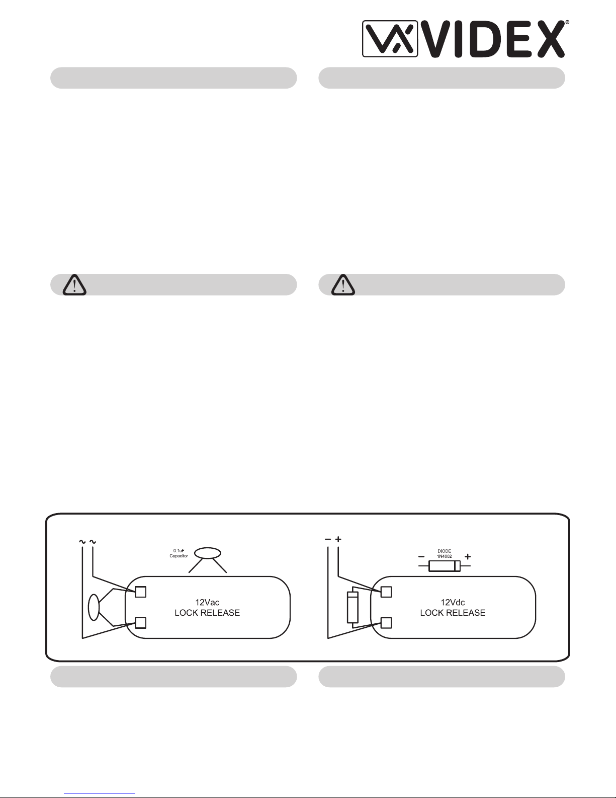
A capacitor must be fitted across the terminals on AC lock
release (Fig.1A) and a diode must be fitted across the
terminals on a DC lock release (Fig.1B) to suppress back
EMF voltages. Connect this components to the lock
releases as shown in figures.
Fig.1A Fig.1B
LOCK RELEASE BACK EMF PROTECTION
AZIONAMENTO SERRATURA- PROTEZIONE DAI DISTURBI
GENERAL DIRECTIONS FOR INSTALLATIONNORME GENERALI D’INSTALLAZIONE
Page 2
We recommend
This equipment is
installed by a
Competent
Electrician,
Security or
Communications
Engineer
Factory - Office
Northern UK Office
(All Countries Support)
(Only UK Support)
VIDEX ELECTRONICS S.p.A
VIDEX LTD
. Via del lavoro,1 63020 MONTEGIBERTO (AP) - ITALY
Phone: (+39) 0734 - 631669 Fax: (+39) 0734 - 632475 www.videx.it e-mail: info@videx.it
Unit 5-7 Chillingam Industrial Estate Chapman Street NEWCASTLE UPON TYNE Ne6 2XX
Phone: 0191 2243174 Fax: 0191 - 2241559 www.videx-security.com
66250330.cdr 26/10/2005
Page 3

Art.VX800N
Installation Instructions
Istruzioni di Installazione
VX800N-2
VX800N-2L
VX800N/F
VX800N/S
VX800N-3
VX800N-3L
Module 2 Relay
Module 2 Relay plus panel illumination
Stand alone unit 2 Relay.Flushmounting
Stand alone unit 2 Relay.Surfacemounting
3 Relay
3 Relay plus panel illumination
Access control system with 2 codes and 2 Relays outputs (3 codes, 3 relays
on VX800N-3.. version).
Personal access code to enter into the “Programming Menu” ( from 4 to 8
digits).
Programming of the activation time of each relay from 1 up to 99 seconds or
latching.
Possibility to activate relay 1 by shorting terminal ”SW1” to GND and relay 2
by shorting terminal “SW2” to GND. Both relays will operate for the
programmed time ( this feature is not available on VX800N-3 version).
Keypad gives out an acoustic (buzzer) signal during the entering of codes
and a continuous melody for 4 or more seconds, according to the number of
mistakes (self protection).
Keypad includes panel illumination (VX800N-..L only) and 2 LED’s to show
the following:
Correct relay code (green LED on for 2 seconds).
Red LED to indicate when in the “programming menu”.
Contacts of the relays are available ( N.O and N.C) with 5A max 24Vac/dc.
Power requirements: 12/24V AC/DC,2VA.
Working temperature: -10 +50°C
To use the system, type in the programmed code and press “ENTER” , the
green LED will illuminate andthe relay will operate for the programmed time.To
cancel remain open time, typein the same code and press “CLEAR”. If awrong
code is entered, a continuous melody will sound for 4 or more seconds,
according to the number of mistakes.
!
!
When the installation is concluded and carried out according to the wiring
diagram, power up the system and program it by following the “VX800N
PROGRAMMING” Flow Chart.
VX800N-2
VX800N-2L
VX800N/F
VX800N-3
VX800N-3L
Modulo a 2 Relè
Module a 2 Relè con illuminazione
Modulo “Stand alone”, montaggio da incasso
Modulo a 3 Relè
Modulo a 3 Relè con illuminazione
Sistema di controllo accessi con 2codicie2usciterelè(3codicie3uscite nella
versione 800N-3)
Codice di accesso al menù di programmazione configurabile (da 4 ad 8
cifre).
Impostazione di ciascun relè per l’attivazione temporizzata (da 1 a 99
secondi) o la commutazione (00 nella programmazione del tempo relè).
Possibilità di attivare i Relè 1 e 2 collegando a massa rispettivamente i
morsetti “SW1” ed “SW2”. I relè funzioneranno per il tempo programmato
(funzione non disponibile nella versione a 3 relè 800N-3).
La tastiera emette dei segnali acustici durante l’utilizzo ed è dotata di autoprotezione in caso di inserimento di codici errati (segnale acustico della
durata di 4 o più secondi).
La tastiera è dotata diilluminazione (solo 800N-..L) e di due LED per indicare
quanto segue:
Inserimento di un codice corretto (LED verde acceso per 2 secondi).
Menù di programmazione attivo (LED rosso acceso).
Contatti relè (C, NO, NC) puliti, 24Vac/dc5Amax.
Tensione di alimentazione: 12/24Vac/dc, 2VA.
Temperatura di lavoro: -10 +50°C
Per utilizzare il sistema, digitale il codice e premere “ENTER”, il LED verde si
accende ed ilrelèfunzionerà per il tempo programmato. Perdisattivareun relè
(impostato per l’attivazione temporizzata o a commutazione di stato), digitare
lo stesso codice e premere “CLEAR”. Se viene digitato un codice errato, la
tastiera emettere un segnale acustico continuo della durata di 4 o più secondi
in base al numero di errori.
Terminata l’installazione secondo lo schema proposto, dare alimentazione
all’impianto e procedere alla programmazione dell’unità seguendo il relativo
flow chart di programmazione
VX800N/S Modulo “Stand alone”, montaggio da superficie
!
!
MODELS
FEATURESCARATTERISTICHE
MODELLI
OPERATION
FUNZIONAMENTO
INITIALIZATION
INIZIALIZZAZIONE
ENTER
“MASTER CODE”
CONFIRM OR CHANGE
“MASTER CODE”
ENTER
“RELAY 1 CODE”
ENTER
“RELAY 1 TIME”
ENTER
“RELAY 2 CODE”
ENTER
“RELAY 2 TIME”
ENTER
“RELAY 3 CODE”
ENTER
“RELAY 3 TIME”
SYSTEM READY TO
USE
FIRST TIME SIX TIMES
1 “ 111111” FA CTO RY
PRESET
TYPE AGAIN SIX TIMES
“1” OR THE NEW CODE 4
TO 8 DIGITS
CODE TO ENABLE
RELAY1
4 TO 8 DIGITS
TWO DIGITS (01 TO 99)
I.E. 05=5 SECONDS
00= REMAIN OPEN
CODE TO ENABLE
RELAY2
4 TO 8 DIGITS
TWO DIGITS (01 TO 99)
ONLY 800-3 VERSION
ONLY 800-3 VERSION
RED LED WILL BE OFF
Press Enter
(Red LED will be
ON)
Press Enter
(Melody)
Press Enter
(Melody)
Press Enter
(Melody)
Press Enter
(Melody)
Press Enter
(Melody)
Press Enter
(Melody)
Press Enter
(Melody)
DIGITARE IL
“MASTER CODE”
CONFERMARE O
CAMBIARE IL
“MASTER CODE”
DIGITARE IL
CODICE REL 1È
DIGITARE IL
TEMPO REL 1È
DIGITARE IL
CODICE RELÈ 2
DIGITARE IL
TEMPO RELÈ 2
DIGITARE IL
CODICE RELÈ 3
DIGITARE IL
TEMPO RELÈ 3
IL SISTEMA è PRONTO
ALL’USO
6 V OLTE 1 “111111”
IMPOSTAZIONE DI
FABBRICA
DIGITARE NUOVAMENTE
6 VOLTE 1 O UN NUOVO
CODICE DA4 A8 CIFRE
CODICE ATTIVAZIONE
REL 1 DA4A 8 CIFREÈ
DUE CIFRE (DA 01 A
99) ES. 05=5 SECONDI
00= COMM. STATO
CODICE ATTIVAZIONE
REL 2 DA4A 8 CIFREÈ
DUE CIFRE
(DA01A 99)
ES. 05=5 SECONDI
DISPONIBILE SOLO
SU VERSIONE 800-3
DISPONIBILE SOLO
SU VERSIONE 800-3
IL LED ROSSO SI
SPEGNE
Premere Enter
(Il LED rosso si
accende)
Premere Enter
(Segnale
acustico)
Premere Enter
(Segnale
acustico)
Premere Enter
(Segnale
acustico)
Premere Enter
(Segnale
acustico)
Premere Enter
(Segnale
acustico)
Premere Enter
(Segnale
acustico)
Premere Enter
(Segnale
acustico)
Page 4

Refer also to the programming flow chart
>
>
>
Enter “MASTER CODE”: first time type six times “1” (111111 factory preset)
and press ENTER (The red LED will illuminate).
Confirm “MASTER CODE”(typingagain the same) or type thenewone (4 to
8 digits) then press ENTER (Melody). Pressing twice the ENTER button
without changing the “MASTER CODE”, will exit from the programming.
Enter the code to enable “RELAY 1” or leave the existing
then press ENTER (Melody).
(4 to 8 digits)
code
Enter the “RELAY 1” operation time (2 digits 01 to 99 I.E. 05=5 seconds, 00=
remain open time) or leave the existing time then press ENTER (Melody).
Enter the code (4 to 8 digits) to enable “RELAY2” or leave the existing code
then press ENTER (Melody).
Enter the “RELAY 2” operation time (2 digits 01 to 99 I.E. 05=5 seconds, 00=
remain open time) or leave the existing time then press ENTER (Melody).
Enter the code(4 to 8 digits) to enable“RELAY 3” (only for 3relay models) or
leave the existing code then press ENTER (Melody).
Enter the “RELAY 3” (only for 3 relay models) operation time (2 digits 01 to
99 I.E. 05=5 seconds, 00= remain open time) or leave the existing time then
press ENTER (Melody).
The system is ready to use (the red LED will be off).
Turnoffpowertocodelock.
Keep “ENTER” button pressed while turning back on the power to the code
lock.
Release “ENTER” button.
The master code is now set at factory master code “111111” (six times“1”).
Proceed with programming for a new system.
To switch off any relay while operating, type in the relevant code then press
the “CLEAR” button.
To operate relays together, set the same code for each relay.
If a wrong code is entered, the system will lock out for 5 seconds which will
increase each time a wrong code is entered. The system will operate only
when the correct code is entered.
In order to achieve the best results from the schematics described it is
necessary to install only original equipment, strictly keeping to the
items indicated on each schematic and follow these General Directions for
Installation:
The system must be installed according to national rules in force, in any
case the running of cables of any intercom unit must be carried out
separately from the mains;
All multipair cables should be compliant to CW1308 specification (0.5mm
twisted pair telephone cable.
Cables for speech line and service should have a max resistance of 10
Lock release wires should be doubled up (Lock release wires and power
supply wires should have a max resistance of 3 );
The cable sizes above can be used for distances up to 50m. On distances
above 50m the cable sizes should be increased to keep the overall
resistance of the cable below the RESISTANCESindicatedabove;
Double check the connections before power up;
Power up the system then check all functions.
>
>
>
>
>
>
>
>
>
>
>
>
>
>
!
!
!
!
!
!
!
INSTRUCTION TO RETURN SYSTEM TO PRESET MASTER FACTORY
CODE
NOTES
VIDEX
LOCK RELEASE BACK EMF PROTECTION
W
W
A capacitor must be fitted across the
terminals on AC lock release (Fig.1A)
and a diode must be fitted across the
terminals on a DC lock release (Fig.1B)
to suppress back EMF voltages.
Connect the components to the lock
releases as shown in figures.
When using intercoms with buzzer call (Art.924/926, SMART1/2, 3101/2,
3001/2 and 3021/2) add one 0,1uF capacitor between terminals 6 and 3.
BUZZER BACK EMF
If help is required for installing or operating this unit please contact our
technical department on +39 0734 631669 (all countries) or +44 0191 224
3174 (Only UK).
Fare riferimento al flow chart
ENTER
>
>
>
Digitare il “MASTER CODE”: 6 volte “1” (111111 impostazione di fabbrica) e
premere (ilLEDrossosiaccende).
Confermare il “MASTER CODE” (digitandolo nuovamente) o digitarne uno
nuovo (da 4 ad 8 cifre) quindi premere ENTER (segnale acustico).
Premendo due volte ENTER senza modificare il “MASTER CODE” si esce
dalla programmazione.
Digitare ilcodice di attivazione(da 4 ad 8cifre) del “REL 1” quindi premere
ENTER .
È
(segnale acustico)
Digitare il tempo di funzionamento del “REL 1” (2 cifre da 01 a 99 Es.05=5
secondi 00=Commutazione di stato) quindi premere ENTER (segnale
acustico).
Digitare ilcodice di attivazione(da 4 ad 8cifre) del “REL 2” quindi premere
ENTER (segnale acustico).
Digitare il tempo di funzionamento del “REL 2” quindi premere ENTER
(segnale acustico).
(solo per laversione800N-3) Digitare il codice diattivazione(da 4 ad 8 cifre)
del “REL 3” quindi premereENTER(segnaleacustico).
(solo per la versione 800N-3) Digitare il tempo di funzionamento del “REL
3” quindi premere ENTER (segnale acustico).
Il sistema è pronto all’uso (il LED rosso si spegne).
Togliere l’alimentazione alla tastiera.
Tenendo premuto il tasto “ENTER”, dare nuovamente alimentazione alla
tastiera.
Rilasciare il tasto “ENTER”.
Il MASTER CODE è nuovamente quello di fabbrica “111111” (6 volte “1”).
Procedere con la nuova programmazione.
Per disattivare uno dei relè mentre è in funzione, digitare il relativo codice
quindi premere il tasto “ ”.
Per far funzionare i relè contemporaneamente, impostare lo stesso codice
di attivazione per ciascun relè.
Se viene digitato un codice errato, l’unitàsi blocca per5 secondi: il tempo di
blocco aumenta in base al numero di errati inserimenti. L’unità funzionerà
solo digitando un codice corretto.
Per eseguire una corretta installazione è necessario impiegare
esclusivamente parti , seguire con scrupolo quanto indicato negli
schemi di collegamento e tenere presenti le norme generali d’installazione:
Realizzare gli impianti secondo le vigenti normative nazionali ed in ogni
caso si consiglia di prevedere, per i conduttori dell’impianto, una
canalizzazione distinta da quella della linea elettrica (vedi paragrafo
seguente per il collegamento alla linea elettrica e l’installazione
dell’alimentatore);
Impiegare conduttori con sezioni tali da avere:
resistenza complessiva inferiore a10 per quelli della lineafonica e di
comando;
resistenza complessiva inferiore a 3 per quelli della serratura e di
alimentazione;
Verificareleconnessioniprimadidarealimentazioneall'impianto;
Alimentare l’impianto ed eseguire il collaudo verificandone tutte le funzioni
>
>
>
>
>
>
>
>
>
>
>
>
>
>
!
!
>
>
!
!
È
È
È
È
È
ISTRUZIONI PER RIPORTARE IL SISTEMA AL CODICE MASTER
IMPOSTATODIFABBRICA
NOTES
CLEAR
VIDEX
W
W
AZIONAMENTO SERRATURA - PROTEZIONE DAI DISTURBI
BUZZER-PROTEZIONE DAI DISTURBI
Per problemi di installazione o funzionamento, contattare il nostro
supporto tecnicoal numero +39 0734 631669(tutti i paesi) o +44 0191 224
3174 (Solo Regno Unito).
L’azionamento della serratura elettrica
può provocare degli spike, per evitare
tale inconveniente si consiglia di
collegare tra iterminalidellaserratura un
condensatore (Fig.1A) o un diodo
(Fig.1B) a seconda che la serratura siain
alternata o in continua.
Utilizzando citofonicon chiamata subuzzer (Art.924/926, SMART1/2, 3101/2,
3001/2 e 3021/2) inserire un condensatore da 0,1uF tra i morsetti 6 e 3.
PROGRAMMING
PROGRAMMAZIONE
Fig.1A Fig.1B
66800053.cdr 09/06/2004
NORME GENERALI D’INSTALLAZIONE GENERAL DIRECTIONS FOR INSTALLATION
Factory - Office
Northern UK Office
(All Countries Support)
(Only UK Support)
VIDEX ELECTRONICS S.p.A
VIDEX LTD
. Via del lavoro,1 63020 MONTEGIBERTO (AP) - ITALY
Phone: (+39) 0734 - 631669 Fax: (+39) 0734 - 632475 www.videx.it e-mail: info@videx.it
Unit 5-7 Chillingam Industrial Estate Chapman Street NEWCASTLE UPON TYNE Ne6 2XX
Phone: 0191 2243174 Fax: 0191 - 2241559 www.videx-security.com
 Loading...