

Page 1
TECHNICAL MANUAL
EDITION 2.1.1
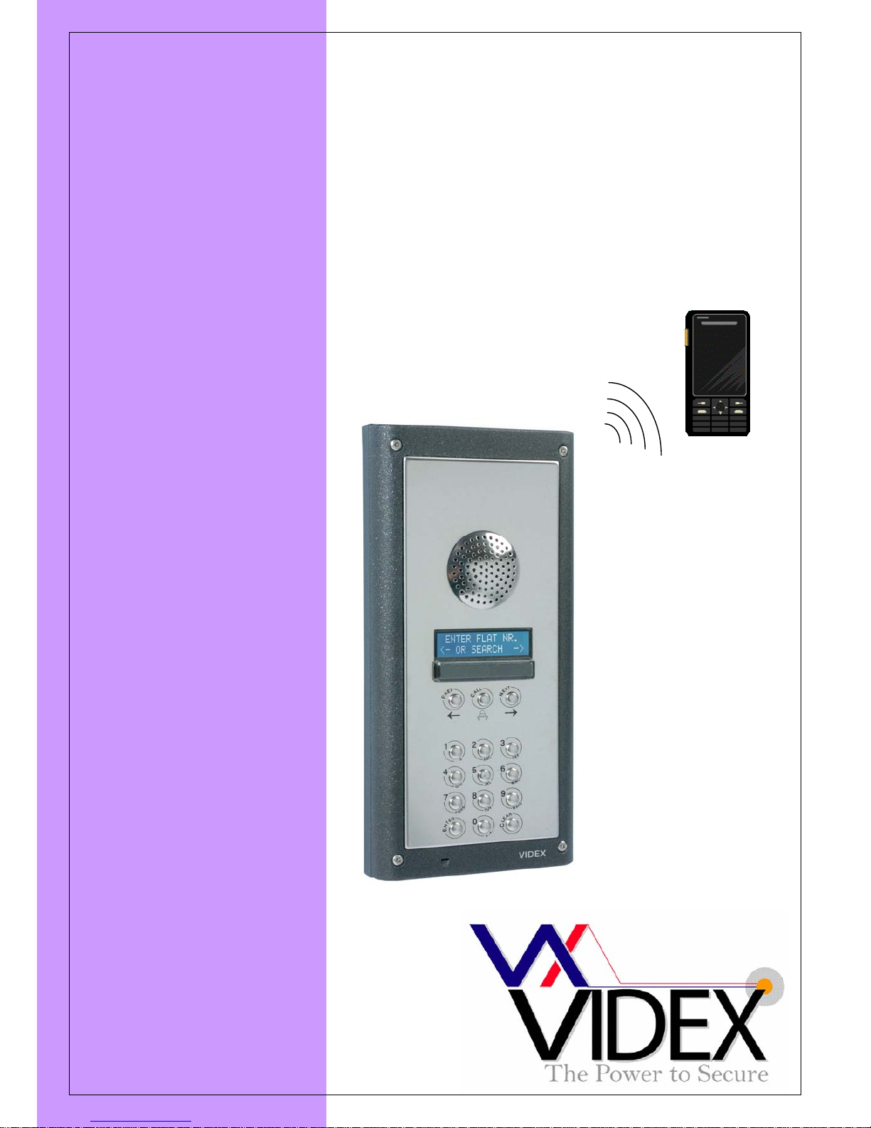
DIGITAL GSM DOOR
INTERCOM SYSTEM
(Up
to 1000 users
)
Page 2

PAGE 2 of 32 DIGITAL GSM INTERCOM TECHNICAL MANUAL VER2.1.1
Page 3

PAGE 3 of 32 DIGITAL GSM INTERCOM TECHNICAL MANUAL VER2.1.1
CONTENTS
MANUAL INTRODUCTION ............................................................................................................................................................................................... 4
SYSTEM INTRODUCTION ................................................................................................................................................................................................ 4
PRECAUTIONARY ADVICE ............................................................................................................................................................................................. 5
SYSTEM COMPONENTS .................................................................................................................................................................................................... 6
DIGITALMODULE.......................................................................................................................................................................................................6
DOORPANELMOUNTINGFRAMES............................................................................................................................................................................7
POWER SUPPLY .................................................................................................................................................................................................................. 7
WIRING DIAGRAMS .......................................................................................................................................................................................................... 8
PUSH TO EXIT BUTTON AND AUXILIARY INPUTS/OUTPUTS ................................................................................................................................ 8
CABLE SIZE GUIDE............................................................................................................................................................................................................ 9
INSTALLATION .................................................................................................................................................................................................................. 9
PANEL CARE ....................................................................................................................................................................................................................... 9
TESTING, POWER UP AND RESET ................................................................................................................................................................................ 10
RESETTOFACTORYDEFAULTS..................................................................................................................................................................................10
PROGRAMMING ............................................................................................................................................................................................................... 10
PROGRAMMING BY THE KEYPAD AND DISPLAY .................................................................................................................................................. 10
1‐ADD/EDITorDELETEanApartment.....................................................................................................................................................................12
2‐ADJUSTINGSYSTEMTIMES
..................................................................................................................................................................................12
3–ADDITIONALSETTINGS.......................................................................................................................................................................................13
4‐ADJUSTINGSYSTEMSETTINGS............................................................................................................................................................................13
EXIT.......................................................................................................................................................................................................................... 14
PROGRAMMING BY PC ................................................................................................................................................................................................... 14
PROGRAMMING BY TEXT MESSAGE ......................................................................................................................................................................... 19
CHANGINGANAPARTMENTSTELEPHONENUMBERS(STN)(STD)........................................................................................................................... 20
CHANGINGANAPARTMENTSACCESSCODE(STC)...................................................................................................................................................20
CHANGINGANAPARTMENTSDIALTOOPENSETTING(STO)..................................................................................................................................
21
CHANGINGANAPARTMENTSTIMEBANDSETTING(STB).......................................................................................................................................21
CHANGINGANAPARTMENTSNAME(STT)..............................................................................................................................................................21
ADDANEWAPARTMENTORQUERYAMEMORYLOCATION(MEM)......................................................................................................................22
SETCALLTIME(SPT).................................................................................................................................................................................................22
SETRELAYTIME(RLT)...............................................................................................................................................................................................23
SETAO(AUXILIARYOUTPUT)TIME(FORAOM=
1ONLY)(AOT)..............................................................................................................................23
SETAO(AUXILIARYOUTPUT)MODE(AOM)............................................................................................................................... ..............................23
DIVERTTIME(DIT)....................................................................................................................................................................................................24
CHANGINGTHEFOURDIGITCODE(CDE).................................................................................................................................................................24
FORCEDDIAL(DLE)...................................................................................................................................................................................................24
STORECREDITBALANCECHECKSTRING(SDL)..........................................................................................................................................................24
STORETHETIMEBAND(TBA)...................................................................................................................................................................................25
MICROPHONE
VOLUME(MIC)............................................................................................................................... ...................................................25
SPEAKERVOLUME(SPK)...........................................................................................................................................................................................25
SPEECHBOARDVOLUME(SBV)................................................................................................................................................................................26
SPEECHBOARDMODE(SBM)...................................................................................................................................................................................26
SYSTEM OPERATION ...................................................................................................................................................................................................... 27
USER COMMANDS ........................................................................................................................................................................................................... 27
CHECKING THE BALANCE (BAL) ................................................................................................................................................................................ 28
UNDERSTANDING THE SIGNAL STRENGTH (SIG) .................................................................................................................................................. 28
DIALLING INTO THE INTERCOM FROM ANOTHER TELEPHONE ........................................................................................................................ 28
RECORD SHEET ................................................................................................................................................................................................................ 28
TROUBLE SHOOTING ...................................................................................................................................................................................................... 29
Page 4

PAGE 4 of 32 DIGITAL GSM INTERCOM TECHNICAL MANUAL VER2.1.1
MANUAL INTRODUCTION
The information in this manual is intended as an installation and commissioning guide for
the digital GSM door intercom system. This manual should be read carefully before the
installation commences. Any damage caused to the equipment due to faulty installations
where the information in this manual has not been followed is not the responsibility of
Videx Security Ltd.
VIDEX run free training courses for engineers who have not installed this system before. Technical
help is also available on 0191 224 3174 during office hours or via e-mail tech@videx-security.com
.
SYSTEM INTRODUCTION
The system is designed to work on the same technology as mobile phones. It enables a
call to be made from an entry point (Door, gate etc), to any telephone number (mobile or
land line). Up to 1000 apartments can be programmed into the door panel, each able to
call two telephone numbers (If the first is busy or not answered, the call can be diverted to
the second). Additionally, each user can have a unique access code up to 6 digits, an
apartment number up to 6 digits, their numbers added to the dial to open list (to allow them
to dial into the panel and release the door/gate), a time band to restrict when this
apartment can receive calls and on the scroll panels, a user name up to 16 characters.
Features of the system include a dry contact relay output, an open collector auxiliary
output, push to exit input and switched 0V auxiliary input. Programming of the telephone
numbers and additional features can be carried out via the panel, PC using a specially
designed Windows program or text message. An additional access control feature is
included for all 2000 telephone numbers allowing a number of callers to open the
gate/door simply by dialling the telephone number of the intercom panel (The intercom
panel will not answer these calls but will activate the relay output).
A SIM card is required for this product but not supplied. It is recommended to choose the
SIM card which has the best coverage for the area in which the intercom panel will be
installed. Both contract and ‘Pay as you go’ SIM cards can be used but if using a ‘Pay as
you go’ we would recommend setting up an automatic top up to avoid running short on
credit and loosing the use of the intercom panel. Alternatively if you already have a
contract mobile phone it should be possible to get a second SIM card and telephone
number on the existing account. For more information contact the SIM card provider or
visit their web sites. Remember to restrict the spend ion the SIM card to avoid
unnecessarily large phone bills due to misuse or fault.
Network provider selection: It is imperative for the reliably operation of the system that
the best network provider for the area is selected. Problems such as network
disconnection can occur if the provider has signal or interference problems for that area.
We would recommend using a GSM signal strength meter to survey the intended antenna
location. Contact Videx for more information on where to purchase a tester. As an initial
check, also go to www.sitefinder.ofcom.org.uk and enter the postcode of the intended
installation. This will show all transmitters in the area. It is advised to choose the closest
one or if there are many then choose a transmitter working on 900MHz as this frequency
works best through obstacles such as walls, buildings etc. The antenna should always be
mounted vertically at the highest point possible. Metal structures and sources of
interference such as power cables, control panels etc can affect signals and so the
antenna should be mounted away from these.
Page 5

PAGE 5 of 32 DIGITAL GSM INTERCOM TECHNICAL MANUAL VER2.1.1
When registering a new SIM you may be asked for the IMEI number. This is the unique
serial number of the GSM intercom and can be found on the rear of the module just below
the SIM holder on a white label. It’s the long number below the barcode.
TIMEBANDNOTE:Thisfeaturerelies onthenetworkproviderstimezonesettingandalsoiftheysupport
NITZ(NetworkIdentityandTimezone).Checkthetimeiscorrectwhenexitingprogrammingmode.Ifthe
time/datereturnedis wrong,itmaybethatthey do not support it in which case this
feature cannot be
used.
PRECAUTIONARY ADVICE
o When mounting the GSM antenna, choose a location which is away from human interaction
and away from the intercom panel. Route the GSM antenna cable from the intercom panel
so that it is separate from the power supply cables and microphone wire. Always mount the
antenna vertically.
o Always ensure the power is off to the intercom panel before inserting or removing the SIM
card.
o New SIM cards will need registering before they can be used. Full details of how this is
done can normally be found in the SIM card pack. It will normally require that the SIM card
is inserted into a mobile phone, a number dialled and instructions followed. While the SIM is
in the mobile phone it would be a good time to disable any PIN codes, call diverts, ring back
and disable features such as voicemail and text alerts. Details of how to do this can be
found on the SIM card provider’s web site or by calling their customer services. Please use
one of the following SIM card providers (Vodafone, TMobile, O2 or Orange). We do not
recommend using 3 at this present time.
o To be able to receive text messages from the intercom panel, the SIM card will require an
SMS service centre number. This is normally preinstalled on new SIM cards but if you are
having trouble receiving SMS messages you will need to confirm this by inserting the SIM
card into a telephone and using the telephones menu options to check it. If a number is not
programmed then it should be programmed while in the telephone (The number can be
obtained from the service provider).
o Voicemail and text alerts must be switched off on the SIM card when using the dial in to
release the door/gate feature. For Vodafone and O2 this can be done while the SIM card is
in the intercom panel. For Orange and T-Mobile the SIM card must be remove and put into
a mobile phone.
o When storing the intercom panel’s telephone number in your own mobile phone avoid using
an obvious name such as ‘Front Door, or ‘My Gate’ as this would make it easy to decipher if
your phone was lost or stolen.
o The PIN request feature must be disabled on the SIM card before using it in the Intercom
panel. It is likely on a new SIM card that it will not be enabled but if it is, it will prevent the
system from working at all.
o This product may not be suitable for installation in hospitals, health care facilities or in the
presence of flammable gases or liquids. Seek advice and authorisation before installing this
product in these locations.
IMPORTANT NOTE ABOUT SIM CARD
When using a pay monthly SIM card you must ask the service provider to put a spend limit
on the account (Vodafone call this service ‘spend checker’). This is to safeguard against
possible problems which could result in a large phone bill at the end of the month. All
providers offer this service. You will need to either ring them or e-mail them to set this up.
Automatic top ups should also have a monthly limit.
Page 6
PAGE 6 of 32 DIGITAL GSM INTERCOM TECHNICAL MANUAL VER2.1.1
SYSTEM COMPONENTS
A system comprises of an intercom panel, power supply, SIM card and antenna. The
intercom panel is of modular design allowing it to be customised to the installation
requirements by including proximity access control, coded access or bioaccess.
DIGITAL MODULE
The digital panel is available for the 4000 Series modular design or flush vandal resistant.
There are two versions in the 4000 series design, name scroll facility which includes a
numeric keypad and 3 buttons to navigate tenants/company names on the display and a
alpha numeric version which includes a numeric keypad and letters A-F. The vandal
resistant panel is also available with letters A-I.
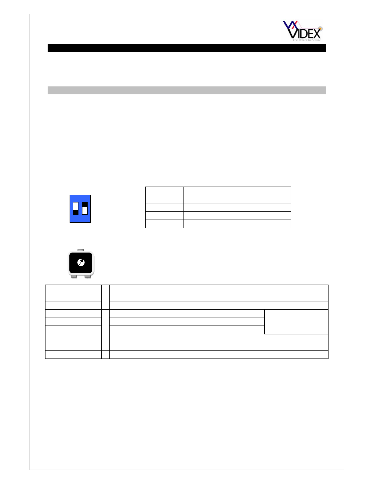
DIP SWITCH SETTINGS
There are 2 dip-switches located on the back of the module. They can be used to alter the
volume from the Door Intercom speaker. Additionally, the volume can also be adjusted
during a call via the telephone keypad.
SPEAKER VOLUME
LCD DISPLAY CONTRAST
CONNECTION DESCRIPTION
+12V 12Vdc – 14Vdc input
0V Ground connection
C Common connection of dry contact relay
NO Normally open connection of dry contact relay
NC Normally closed connection of dry contact relay
AO Auxiliary output switched 0V (Open collector output)
PTE Exit button input switched 0V (0V to trigger)
AI Auxiliary input switched 0V (0V to trigger, triggers AO)
ANTENNA
The GSM antenna connects to the SMA female bulkhead on the rear of the module. A
GSM antenna with a SMA male connector should be used.
Note: An antenna must always be connected and positioned vertically.
Note: Always route the GSM cable away from the microphone wires and the power
supply wires to avoid interference on the speech channels.
1 2 GAIN (dB)
ON ON 6
ON OFF 12
OFF ON 18
OFF OFF 23.5
ON
1 2
Relay contacts:
3A@24Vdc
3A@120Vac
Adjust the LCD contrast by turning the pot on the
rear of the panel next to the terminal connector.
Page 7

PAGE 7 of 32 DIGITAL GSM INTERCOM TECHNICAL MANUAL VER2.1.1
DOOR PANEL MOUNTING FRAMES
Both surface and flush mounting frames are available. The size of the frame will depend
on the number of modules that make up the door panel. The last digit of the frame code
indicates the number of modules it will take. Frames are available in gun metal gray finish,
chrome finish (Suffix \C to the frame code) or gold finish (Suffix \G to the frame code).
Flush frames:
Surface frames:
POWER SUPPLY
The GSM intercom panel is designed to work with power supplies in the range or 1214Vdc. The power supply should be capable of supplying a constant current of no less
than 1 amp (If the system is to work with failsafe lock releases or magnetic locks we would
recommend a minimum of 2 amps). The following Videx power supplies can be used:-
AMR2-12 12-14Vdc 2A switched mode PSU
Art.521B 13.5Vdc 1A DIN box PSU
SP29 13.8Vdc 2A boxed PSU with battery backup facility
SP28 13.8Vdc 3A boxed PSU with battery backup facility
Page 8
PAGE 8 of 32 DIGITAL GSM INTERCOM TECHNICAL MANUAL VER2.1.1
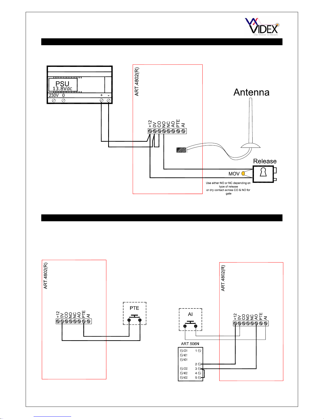
WIRING DIAGRAMS
PUSH TO EXIT BUTTON AND AUXILIARY INPUTS/OUTPUTS
Connections for push to exit button
Connections for auxiliary input (Switched 0V)
and auxiliary output (Connected to 506N relay)
Auxiliary output is also triggered by pressing 6
on the handset during a call.
Page 9
PAGE 9 of 32 DIGITAL GSM INTERCOM TECHNICAL MANUAL VER2.1.1
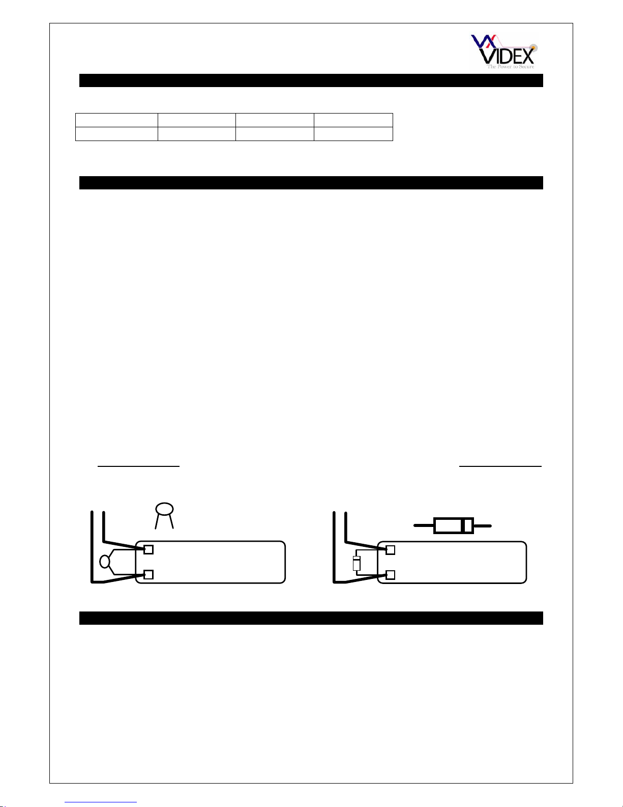
CABLE SIZE GUIDE
Connections for power supply output to intercom panel and lock release connections.
20m 50m 100m
Connections
0.5mm² 1.0mm² 1.5mm²
The power supply should be located as close to the intercom panel as possible for best performance.
Maximum acceptable resistance for above cables = 3Ω
INSTALLATION
- Check that all components are free from damage before installing (Do not proceed with
installation in the event of damage).
- Keep all packaging away from children.
- Do not obstruct the ventilation openings or slots on any of the devices.
- All connections to mains voltages must be made to the current national standards (IEE
Wiring regulations)
- Install an appropriate fused spur or isolation switch to isolate the mains.
- Isolate the mains before carrying out any maintenance work on the system.
- Avoid water ingress into the rear of the module, always seal the module frame after
installation using a suitable silicon based sealant.
- All intercom and access control cables must be routed separately from the mains.
Lock release back EMF protection : A capacitor must be fitted across the terminals on
an AC lock release and a diode must be fitted across the terminals on a DC lock release
as shown in the diagrams below to suppress back EMF voltages.
LOCK RELEASE
12V AC
~~
0.1uF capacitor
+
-
1N4002
+
-
12V DC
LOCK RELEASE
DIODE
PANEL CARE
The door panel’s facia is either mirror finish stainless steel, brushed stainless steel or matt
finish aluminium. It is important that the facia is cleaned on regular occasions to prevent
dirt build up and tarnishing of the metal. A general household metal polish can be used but
care should be taken to follow the grain of the metal when polishing and also avoid any
polish build up around the call buttons which may prevent the buttons from operating
correctly.
Page 10

PAGE 10 of 32 DIGITAL GSM INTERCOM TECHNICAL MANUAL VER2.1.1
TESTING, POWER UP AND RESET
After connecting the power supply, antenna, lock output and auxiliary devices as shown in
this manual and before powering up a SIM card must be installed. The SIM holder can be
found on the back of the module under the label ‘SIM’. A SIM card from any supplier can
be used. Simply push the SIM card in (It will only fit one way). IMPORTANT: Replace the
label over the SIM hole.
- Check all the connections have been made correctly and then power up the system.
- The GSM intercom requires approximately 30 seconds too initialise properly. We
recommend not sending SMS messages or pressing buttons during this time.
- From power up; the panel display will first show the software version number for a few
seconds and then ‘WAIT’. After a delay the display will show the standby message.
- Once initialised, you can begin programming.
RESET TO FACTORY DEFAULTS
There are two reset modes available. The first will reset the master code only and the
second will reset everything and clear all stored telephone numbers.
RESET THE MASTER CODE TO 1111
1. Power down the intercom panel
2. Hold down the ‘Enter’ button (on VR4802 or 4802) or the ‘4’ button (on 4802R)
3. Power up continuing to hold the button
4. Wait for the display to revert to the standby message
5. The master code is now reset to 1111
FULL RESET (WARNING: THIS WILL COMPLETELY FORMAT THE MEMORY)
1. Power down the intercom panel
2. Hold down the ‘9’ button (on VR4802 or 4802) or the ‘3’ button (on 4802R)
3. Power up continuing to hold the button
4. When the display shows ‘WAIT’ release the button
5. After a delay, all settings are returned to factory defaults
The panel software is the same for both Alpha (VR4802, 4802) and scroll (4802R) style
panels. To initially set the panel, power up with the ‘7’ (on VR4802 or 4802) or power up
with the ‘2’ pressed (on 4802R). Keep the button pressed until the display reverts to the
standby message.
PROGRAMMING
Programming can be carried out either by the panel keypad & display or by PC.
Additionally, programming can be carried out via SMS text messages.
PROGRAMMING BY THE KEYPAD AND DISPLAY
The programming menu is protected by a 4 digit engineer’s code. The factory default is
1111. To enter programming mode, press ‘0’ followed by the 4 digit code and then press
enter. The programming flow chart is on the following page. An explanation of each
programming option can be found on the pages that follow.
Page 11

PAGE 11 of 32 DIGITAL GSM INTERCOM TECHNICAL MANUAL VER2.1.1
Page 12

PAGE 12 of 32 DIGITAL GSM INTERCOM TECHNICAL MANUAL VER2.1.1
1 - ADD/EDIT or DELETE an Apartment
From the main menu page, press ‘1’ for APT then press either ‘1’ to add or edit an apartment, ‘2’ to
delete an apartment or ‘5’ to return to the main menu page.
ADD/EDIT
MEMORY LOCATION; Memory locations are between 0 & 999. The memory location is simply a
position in memory to store a single apartments/persons details.
TELEPHONE NUMBER; This is the first telephone number to be called when a user enters the
apartment number for this user. The telephone number can be up to 16 digits.
DIVERT NUMBER; If the first number is not answered or busy then this number will automatically
be called. The number can be up to 16 digits. Leave this blank if there is no number to divert to.
APARTMENT NUMBER; The apartment number is the number entered by the caller. The number
can be up to 6 digits/characters.
ACCESS CODE; Each user can have their own personal access code to gain enter to the
premises The access code can be up to 6 digits. When entered by a user it will activate the lock
relay for the programmed time period. Leave blank if not required.
DTO; It is possible to allow users to dial the telephone number of the panel to activate the lock
relay. To activate this feature enter ‘1’. To disable this feature enter ‘2’. When this feature is active,
a user calling from either the telephone number or divert number will activate the relay for the
programmed time. The call will then be dropped automatically. If this option is set to ‘2’, the call will
be dropped automatically.
TIMEBAND; A time band is used to set when a user can receive calls. For example a user may
only want to receive calls during certain hours of the day. There are 10 time bands available (0-9).
Time band 0 is set to all day (00:00 – 23:59) and cannot be changed where as all the other time
bands can be programmed.
APARTMENT NAME; The apartment name feature is only used on the scroll style panels. On this
type on panel it is possible for callers to scroll through these names on the panel. The names can
be up to 16 characters long. Entering these names is similar to sending a text on a mobile phone.
You use the numeric keypad as shown in the table below.
DELETE
MEMORY LOCATION; Memory locations are between 0 & 999. The memory location is simply a
position in memory to store a single apartments/persons details. Enter the memory location to
delete and press enter. All information in that memory location will be deleted.
2 - ADJUSTING SYSTEM TIMES
From the main menu page, press ‘2’ for TIMES then press either ‘1’ for call time, ‘2’ for divert time,
‘3’ for relay time, ‘4’ for aux out time or ‘5’ to return to the main menu page.
CALL TIME; The call time can be between 1 - 255 seconds. The call time starts from when the
enter button is pressed and is the time before the call automatically clears down.
DIVERT TIME; The divert time can be between 1 – 255 seconds. The divert time is the wait time
for a call to be answered before it attempts to divert the call to the stored divert number (If
available). If no number is stored, the call will continue with the first number until answered or the
call time expires.
RELAY TIME; The relay time can be between 1 – 255 seconds.
AUX TIME; The auxiliary output (AO) time can be between 1 – 255 seconds.
1 = <SPACE>.& 2 = ABC 3 = DEF
4 = GHI 5 = JKL 6 = MNO
7 = PQRS 8 = TUV 9 = WXYZ
ENTER = FINISHED 0 = +-*/ CLEAR = DELETE
Page 13

PAGE 13 of 32 DIGITAL GSM INTERCOM TECHNICAL MANUAL VER2.1.1
3 – ADDITIONAL SETTINGS
From the main menu press ‘3’ for display and language settings then choose 1 to adjust the main
display text, 2 to adjust the second display text and 3 to change the display language.
LCD1; The display text is usually ‘ENTER NUMBER’. This can be changed to any message up to
16 characters in length. Entering these names is similar to sending a text on a mobile phone. You
use the numeric keypad as shown in the table below.
LCD2; This display text will switch back and forth with the text from LCD1 on an 8 second cycle.
This can be changed to any message up to 16 characters in length. Entering these names is
similar to sending a text on a mobile phone. You use the numeric keypad as shown in the table
below.
LANGUAGE; The messages displayed on the display during operation can be shown in a number
of languages. Choose from the options available and press enter to select.
1=EN English
2=IT Italian
3=DU Dutch
4 - ADJUSTING SYSTEM SETTINGS
From the main menu page, press ‘4’ for SETTINGS then press either ‘1’ to set the auxiliary mode,
‘2’ to change the master code, ‘3’ for audio options, ‘4’ for timebands or ‘5’ to return to the main
menu page.
AUX MODE; The auxiliary mode controls how the AO output terminal operates. When set to ‘1’ the
output is manually triggered by the user by pressing 6 on the telephone during a call or by
triggering the AI terminal (0V triggered). When set to ‘0’ the AO terminal will trigger automatically
during a call for the full duration of the call and when set to ‘2’ the AO terminal will trigger
automatically upon a call for the programmed AUX TIME.
MC; The master code must be 4 digits but can be any 4 digit number. The factory default is 1111.
AUD; Entering this mode will take you to another menu page with the following options:-
The speech board ‘SB’ is the voice annunciation you here during a call. Both the
volume and the setting of this can be adjusted. The MIC VOL and SPK VOL are the speech
volumes during a call. Press 1 for speech board volume, 2 for speech board mode, 3 for
microphone volume, 4 for speaker volume or 5 to return to the main menu.
SBVOL; The volume can be from 0 – 7. 0 = lowest, 7 = highest.
SBMODE; Press ‘1’ to disable the voice annunciation, ‘2’ to set the voice annunciation to
speak numbers individually (i.e. 100 would be spoken as One, Zero, Zero) or ‘3’ to set the
voice annunciation to speak the numbers combined (i.e. 100 would be spoken as One
Hundred).
1 = <SPACE>.& 2 = ABC 3 = DEF
4 = GHI 5 = JKL 6 = MNO
7 = PQRS 8 = TUV 9 = WXYZ
ENTER = FINISHED 0 = +-*/ CLEAR = DELETE
Page 14

PAGE 14 of 32 DIGITAL GSM INTERCOM TECHNICAL MANUAL VER2.1.1
MICVOL; The microphone volume can be between 0 – 9. 0 = lowest, 9 = highest.
SPKVOL; The speaker volume can be between 0 – 9. 0 = lowest, 9 = highest.
TIMEBAND; There are 10 time bands available (0-9). Each user can be attached to one time
band. Time band ‘0’ is the default time band and is set to all day (00:00 – 23:59) and can’t be
changed. On the time band page, press 1-9 and then ‘enter’ to edit one of the time bands. On the
following page enter the ON time and the OFF time. The 24 hour clock must be used and the ON
time must be lower than the OFF time. Any users attached to this time band will only be able to
receive calls between this ON & OFF time. Remember to use the 24hr clock.
EXIT
To exit from the programming menu from the main menu press ‘5’. When exiting the programming
the display will first show ‘END’ then show the signal strength received from the service provider
and also the time & date sent by the service provider. The signal strength will be between 0 – 31 or
99. Ideally the signal strength should be as close to 31 as possible. The lower the number, the
weaker the signal. Signal strengths lower than 10 may cause operational problems such as loss of
speech quality (and possibly missing DTMF tones) and network loss. A signal strength of 99
indicates it couldn’t be detected.
Exit from the programming will also happen automatically if no buttons are pressed for 30 seconds.
PROGRAMMING BY PC
USB DRIVER
IMPORTANT: Before connecting the GSM unit to the PC and before installing the GSM
PC program, first install the driver for the USB adapter which can be found on the supplied
CD in the following folder:-
D:\FT232Driver\CDM20814.exe Where D is the letter of your CD drive.
SOFTWARE SETUP
Run the setup program (setup.exe) from the CD. Follow the on screen instructions to
complete the setup. Please note, the PC must be Window XP PRO or later and have the
.NET 4 framework installed. (The .NET 4 framework can be found on the CD or will be
downloaded from the internet during install).
After completing the setup, the program will be available from your start menu as Videx
GSM. Before running the program, connect the supplied USB cable between a USB port
on your PC and the GSM unit. Run the program and the following screen should appear:-
Page 15

PAGE 15 of 32 DIGITAL GSM INTERCOM TECHNICAL MANUAL VER2.1.1
When the program loads, it checks all available ports for the GSM unit. If found, the GSM
unit goes online with the PC. From the main screen it is possible to:-
Check signal strength:
Click on update to retrieve the signal strength from the unit. The
signal strength will be between 1 & 31 whereby 31 is excellent and 1
is poor. A signal strength of at least 10 is required for the system to
work satisfactorily.
Check balance on pay as you go SIM’s:
For this to work you must first store the check string required by the
service provider on the settings page. For example, the string
*#1345# is used by Vodafone to retrieve your current balance.
Once this has been stored and uploaded to the unit, clicking the
Check Balance button will retrieve it.
Check firmware version:
Click the Check Firmware button to retrieve the firmware version of the GSM unit. This will
be useful to technical support should you need to call and can also give you an indication
of functions available as identified in the back of this manual.
Communication port setup:
Although the communication should setup automatically
when the program is started it is also possible to
manual setup the communication port.
To setup manually, first press the Refresh List button
which will find all available communication ports, Then
either select from the drop down list, the port which is connected to the GSM unit and
press the Auto Detect button to check for the device or just simply click on the Auto Detect
button to check all available ports. If the device is found, the status will change to online.
Page 16

PAGE 16 of 32 DIGITAL GSM INTERCOM TECHNICAL MANUAL VER2.1.1
Mobile phone:
The mobile phone can be used like a normal mobile phone to make calls.
This can be useful when setting up the GSM unit’s SIM card with functions
such as switching off voice mail and text alert or listening to the SIM cards
balance through the intercom’s speaker. Simply type the number to call on
the keypad and click the send button . Ti end the call press the button
and to clear the display press the C button.
Please note: After making any changes to the settings and stored telephone
numbers on the PC, they must then be uploaded to the unit before they will take
effect.
GENERAL SETTINGS:
The general settings page has the following programmable options:
Call Time: Maximum length of a call before it automatically clear down (1-255 Seconds)
Relay Time Relay activation time (1 – 255 Seconds, 0 = latching)
Aux Out Time: Auxillary output AO terminal, switched 0V time ((1 – 255 Seconds, 0 = latching)
Divert Time: The time a phone is allowed to ring before the unit cancels the call and diverts to the
second number, of programmed.(1 – 255 seconds)
Aux Mode: The AO terminal is a switch 0V output. It can be programmed to trigger by the end
user pressing 6 on their telephone during a call or can be setup to switch on when a
call is made and stay on for the length of the call. The two options are available in
the drop down box.
Master Code: The master code must be 4 digits (Factory default 1111) and is required when using
the SMS facilities on the GSM unit, entering the programming menu and also when
dialling in to the unit from a number which is not stored.
Balance Check String: The balance check string allows the balance on certain pay as you go SIM cards to
be checked. This must be stored to allow the balance to be checked.
Speech board Volume: The volume of the voice annunciation messages. The higher the number the higher
the volume.
Page 17

PAGE 17 of 32 DIGITAL GSM INTERCOM TECHNICAL MANUAL VER2.1.1
Speech board Mode: The voice annunciation can be set to speak the number being called as a whole
number (i.e. 100 would be spoken as ‘One hundred’) or can be set to speak the
numbers individually (i.e. 100 would be spoken as ‘One’ ‘Zero’ ‘Zero’). Alternatively
the speech board can be disabled from the drop down menu.
Speaker volume: The speaker volume can be between 0 & 9. The higher the number the higher the
volume.
Speaker volume: The microphone volume can be between 0 & 9. The higher the number the higher
the volume.
Time bands: There are 10 time bands. The first is fixed to all day and cannot be changed , the
other 9 can be set to any times (Ensure the ON time is lower than the OFF time).
Language: The language of the messages show on the LCD display
Display Line 1: The standby message on the LCD display
Switched display: A second message which switches with the one above every 8 seconds.
CALL SETUP:
From the call setup page it is possible to assign up to 2 telephone numbers to each of the 1000 available
locations. The divert telephone number will be used if the call is busy or not answered and will divert to this
number after the divert time has elapsed. If no divert number is stored, the first number will continue to ring
until the call times out.
Apartment No. can be up to 6 digits and is the number entered by a caller to initiate a call.
Apartment Name is only used on panels with the scroll facility. It is used to store names which can be
scrolled through on the panel. The names can be up to 16 characters long.
Access Code is a unique to each user code that can be used to release the door/gate via the door panel
keypad. The code can be up to 6 digits.
DTO when set means that the telephone number and the divert number for that user can dial into the panel
and release the door/gate.
TB Select a time band for the user. This user will only be able to receive calls within this timeband.
FILE MENU:
From the file menu it is possible to create a new data file, open an existing
data file, save the current data file and print. These options are available
online or offline allowing the data file to be created on or off site for
convenience.
Page 18

PAGE 18 of 32 DIGITAL GSM INTERCOM TECHNICAL MANUAL VER2.1.1
The exit option will close the program.
DATA MENU:
The data menu is only available when online. From
here it is possible to upload the information from the
PC to the GSM unit and download information from
the GSM unit to the PC. Both upload and download
have several options which include the facility to
Download all data or upload/download only a section
of data which is required and has been changed.
When uploading it is recommended to only upload
the range of locations in use as the upload for the
complete memory will take a long time.
SORT MENU:
From the sort menu it is possible to put all the users
data in order of apartment name or apartment
number. On panels using the scroll facility we would
recommend sorting into apartment name order.
PC Requirements:-
Windows XP Service Pack 3 or Later
.Net framework 4 or later
CD Drive
USB port
Page 19

PAGE 19 of 32 DIGITAL GSM INTERCOM TECHNICAL MANUAL VER2.1.1
PROGRAMMING BY TEXT MESSAGE
Programming by text message is a simple way to change the apartment programming
remotely. This can include changing an apartments telephone numbers, access code,
name or settings. If you have a large number of changes you may find programming easier
with the PC software or through the keypad and display.
APARTMENT SETTINGS PROGRAMMING COMMANDS
DESCRIPTION CODE EXAMPLE SETTINGS DEFAULT PAGE
Apt primary telephone no. STN 1111STNn:”01912243174” n = apt number N/A 20
Apt divert telephone no. STD 1111STDn:”01912241559” n = apt number N/A 20
Apartment access code. STC 1111STCn:”123456” n = apt number N/A 20
Apartments dial to open setting STO 1111STOn:z n = apt number
z = 1 or 2
2 21
Apartments time band STB 1111STBn:z n = apt number
z = 0 - 9
0 21
Apartments name STT 1111STTn:”Mr Smith” n = apt number N/A 21
Add or query a memory location MEM 1111MEMnnn? nnn = 000 - 999 N/A 22
GENERAL SETTINGS PROGRAMMING COMMANDS
DESCRIPTION CODE EXAMPLE SETTINGS DEFAULT PAGE
Speech time SPT 1111SPTnnn nnn = 001 -255 040 22
Relay time RLT 1111RLTnnn nnn = 000 - 255 5 23
Aux Out time AOT 1111AOTnnn nnn = 000 - 255 5 23
Divert time DIT 1111DITnnn nnn = 001 – 255 15 24
Aux Out mode AOM 1111AOMn n = 0 or 1 1 23
Speech board volume SBV 1111SBVn n = 0 - 7 7 26
Speech board mode SBM 1111SBMn n = 1 - 3 3 26
Mic volume MIC 1111MICn n = 0 – 9 7 25
Speaker volume SPK 1111SPKn n = 0 – 9 7 25
Master code change CDE 1111CDEnnnn nnnn = newcode 1111 24
Time bands TBA 1111TBAn”hhmmHHMM” n = 1-9
hhmm = Start
HHMM = End
00:00 – 23:59 25
Store balance check dial string SDL 1111SDL”*#1345#” N/A N/A 24
USER COMMANDS
DESCRIPTION CODE EXAMPLE SETTINGS DEFAULT PAGE
Check GSM signal strength SIG 1111SIG? N/A N/A 27
Check software version VER 1111VER? N/A N/A 27
Dial a number DLE 1111DLE”123” N/A N/A 24
Trigger the relay RLY 1111RLY N/A N/A 27
Trigger the auxiliary output AUX 1111AUX N/A N/A 27
Check credit balance BAL 1111BAL? N/A N/A 27
Latch the relay RLA 1111RLA N/A N/A 27
Unlatch the relay RUL 1111RUL N/A N/A 27
Latch the auxiliary output ALA 1111ALA N/A N/A 27
Unlatch the auxiliary output AUL 1111AUL N/A N/A 27
When sending text messages there may be a delay from when you send the message to when it is
received by the intercom panel depending on how congested the network is.
Page 20

PAGE 20 of 32 DIGITAL GSM INTERCOM TECHNICAL MANUAL VER2.1.1
CHANGING AN APARTMENTS TELEPHONE NUMBERS (STN) (STD)
Each apartment can have up to 2 telephone numbers, a primary number and a divert
number should the first not answer or is busy. The STN code stores the primary number
and the STD code stores the diverted telephone number. The messages to change
numbers are as follows (Replace STN with STD when changing the divert numbers).
1111STNn:”yyyyyyyyyyy” Change the primary telephone number to yyyyyyyyyyy
for apartment n. n can be 1-6 digits.
1111STNn:”yyyyyyyyyyy”? Change the telephone number to yyyyyyyyyyy in
apartment n and send a confirmation text message to
confirm the storage of the new number.
1111STNn:? Query the telephone number stored for apartment n. A
text message will be sent to the sender with the stored
number for that apartment.
1111STNn:”” Delete the telephone number stored for apartment n.
1111STNn””? Delete the telephone number stored for apartment n. A
text message will be sent to the sender with the delete
confirmation for that location.
Example: To change the primary number to 01912243174 and the divert number to
01912241558 for apartment 100 would be the following two SMS messages:-
1111STN100:”01912243174”?
1111STD100:”01912241558”?
The ? is optional
CHANGING AN APARTMENTS ACCESS CODE (STC)
Each apartment can have a unique access code from 1-6 digits. To change or query this
code send the following commands:-
1111STCn:”yyyyyy” Change the code to yyyyyyyy for apartment n. n can be
1-6 digits.
1111STCn:”yyyyyy”? Change the code to yyyyyyyy in apartment n and send a
confirmation text message to confirm the storage of the
new code.
1111STCn:? Query the code stored for apartment n. A text message
will be sent to the sender with the stored code for that
apartment.
1111STCn:”” Delete the code stored for apartment n.
1111STCn””? Delete the code stored for apartment n. A text message
will be sent to the sender with the delete confirmation for
that location.
Page 21

PAGE 21 of 32 DIGITAL GSM INTERCOM TECHNICAL MANUAL VER2.1.1
Example: To change the code to 123456 in apartment 20 would be the following SMS
message:-
1111STC20:”123456”?
The ? is optional
CHANGING AN APARTMENTS DIAL TO OPEN SETTING (STO)
Each apartments telephone numbers can be used as dial to open numbers. When this
setting is set to 1, dial to open is enabled and when set to 2, dial to open is disabled. When
enabled, calling the digital panel’s telephone number from that apartments telephone
numbers will release the door and end the call automatically without any charge. When
this feature is disabled, dialling the digital panel’s telephone number from that apartments
telephone numbers will open the speech to the panel and allow all functions available
during a call.
1111STOn:y Change the dial to open setting to y for apartment n. n
can be 1-6 digits. y can be 1 to enable to 2 to disable.
1111STOn: y? Change the dial to open setting to y for apartment n. n
can be 1-6 digits. y can be 1 to enable to 2 to disable. A
confirmation text message is returned to confirm the
storage of the new setting.
1111STOn:? Query the dial to open setting for apartment n. A text
message will be sent to the sender with the stored
setting for that apartment.
CHANGING AN APARTMENTS TIME BAND SETTING (STB)
Each apartment’s calls from the panel can be restricted to a certain time band. There are
10 time bands to choose from 0-9. 0 is a 24-7 time band with no restriction of calls while 19 can be programmed to any required times. To change the time band associated with a
certain apartment:
1111STBn:y Change the time band setting to y for apartment n. n
can be 1-6 digits. y can be 0-9.
1111STBn: y? Change the time band setting to y for apartment n. n
can be 1-6 digits. y can be 0-9. A confirmation text
message is returned to confirm the storage of the new
setting.
1111STBn:? Query the time band setting for apartment n. A text
message will be sent to the sender with the stored
setting for that apartment.
CHANGING AN APARTMENTS NAME (STT)
Each apartment can have a unique name from 1-16 characters in length. To change or
query this name send the following commands:-
Page 22

PAGE 22 of 32 DIGITAL GSM INTERCOM TECHNICAL MANUAL VER2.1.1
1111STTn:”yyyyyyyyyy” Change the name to yyyyyyyy for apartment n. n can be
1-6 digits.
1111STTn:”yyyyyyyyyy”? Change the code yyyyyyyy in apartment n and send a
confirmation text message to confirm the storage of the
new name.
1111STTn:? Query the name stored for apartment n. A text message
will be sent to the sender with the stored code for that
apartment.
1111STTn:”” Delete the name stored for apartment n.
1111STTn””? Delete the name stored for apartment n. A text message
will be sent to the sender with the delete confirmation for
that location.
NOTE: IF A SPACE IS REQUIRED ON THE DISPLAY SUBSTITUE IT WITH THE CHARACTER ‘>’ IN THE SMS MESSAGE. THIS
IS BECUASE SPACES IN THE SMS MESSAGE ARE DISCARDED.
ADD A NEW APARTMENT OR QUERY A MEMORY LOCATION (MEM)
There are 1000 memory locations available in the Digital panel (000-999). Each of these
memory locations stores apartment’s settings. It is possible to query change or add an
apartment using the following command:-
1111MEMnnn? Query a memory location. A text message will be
returned with all the settings for that apartment. nnn =
memory location 000-999
1111MEMnnn”yyyyyyyyyy”,”zzzzzzzzzz”,”aaaaaa”,”cccccc”,d,b,”tttttttttt”?
nnn = Memory location 000-999
yyyyyyyyyy = Primary telephone number
zzzzzzzzzz = Divert telephone number
aaaaaa = Apartment number from 1-6 digits
cccccc = Access code from 1-6 digits
d = Dial to open setting, 1 = enabled, 2 = disabled
b = Time band, 0-9
ttttttttt = Apartment name, 1 to 16 characters.
The ? is optional
NOTE: Using this command it is possible to change all or only some of the apartments
settings. To leave a setting unchanged simply don’t enter anything in that section of that
setting but remember to add the comma.
For example to change everything except the apartment number send:-
1111MEMnnn”yyyyyyyyyy”,”zzzzzzzzzz”,,”cccccc”,d,b,”tttttttttt”?
To change only the primary and divert number send:-
1111MEMnnn”yyyyyyyyyy”,”zzzzzzzzzz”,,,,,?
SET CALL TIME (SPT)
The call time is the maximum time in seconds that a call can last before the intercom panel
automatically clears the call down. The time can be from 1 seconds up to 255 seconds
Page 23

PAGE 23 of 32 DIGITAL GSM INTERCOM TECHNICAL MANUAL VER2.1.1
and begins from when the call/enter button is pressed. The default time is 40 seconds. The
following messages are used to set/check the maximum call time.
1111SPTnnn Store the time nnn (e.g. nnn = 001 - 255 seconds).
1111SPTnnn? Store the time nnn (e.g. nnn = 001 - 255 seconds). Also
send a confirmation text back to the sender.
1111SPT? Query the current stored time. A text message will be
sent to the sender showing the stored time.
SET RELAY TIME (RLT)
The relay time can be from 001 – 255 seconds or latching (Set the relay time to 000 for
latched mode. In latch mode, the relay will stay energised until the command is send
again).
1111RLTnnn Store the time, nnn = time in seconds.
1111RLTnnn? Store the time nnn = time in seconds. Also send a
confirmation text back to the sender.
1111RLT? Query the current stored time. A text message will be
sent to the sender showing the stored time.
SET AO (AUXILIARY OUTPUT) TIME (FOR AOM = 1 ONLY) (AOT)
The AO time can be from 001 – 255 seconds or latching (Set the AO time to 000 for
latched mode). This option is only relevant for aux mode 1.
1111AOTnnn Store the time nnn = time in seconds.
1111AOTnnn? Store the time nnn = time in seconds. Also send a
confirmation text back to the sender.
1111AOT? Query the current stored time. A text message will be
sent to the sender showing the stored time.
SET AO (AUXILIARY OUTPUT) MODE (AOM)
There are three modes of operation for the AO terminal:-
User activated: n= 1; To activate the AO terminal either short g to 5 (Auxiliary 1 input) or
press 6 on the telephone during a call.
Call activated: n= 0; AO will activate when a call begins and deactivate when the call ends.
Call activated (Timed): n = 2; AO will activate when a call begins and deactivate when the
AUX TIME expires.
1111AOMn Store the mode n = 0 - 2.
1111AOMn? Store the mode n = 0 - 2. Also send a confirmation
text back to the sender.
1111AOM? Query the current stored mode. A text message will be
sent to the sender showing the stored mode.
Page 24

PAGE 24 of 32 DIGITAL GSM INTERCOM TECHNICAL MANUAL VER2.1.1
DIVERT TIME (DIT)
The divert time is the number of seconds to wait for a call to be answered before diverting
to the second number. The default time is 15 seconds (The count down begins from when
the call/enter button is pressed, but is refreshed when the telephone begins to ring) and
can be set to 001 – 255 seconds).
1111DITnnn Store the time nnn = time in seconds.
1111DITnnn? Store the time nnn = time in seconds. Also send a
confirmation text back to the sender.
1111DIT? Query the current stored time. A text message will be
sent to the sender showing the stored time.
CHANGING THE FOUR DIGIT CODE (CDE)
The four digit code can be any combination of numbers 0-9 but must be 4 digits long. The
code allows access to the programming menu in programming mode and must be used
when sending text messages to the intercom panel. The following message changes the
code:-
1111CDEnnnn nnnn = new 4 digit code
FORCED DIAL (DLE)
A useful feature of the Intercom panel is its ability to call a number sent to it in a text
message. This feature can be used when setting up the SIM card. For example, disabling
the voicemail facility or disabling automatic SMS messages or missed calls. Any number
up to 15 digits can be called and the call will last for a maximum of 40 seconds. The
example below would switch off voicemail on a Vodafone SIM card. Substitute the
Vodafone number for other service providers (See important note on page 19).
1111DLE”1210“ Dial 1210 for the intercom panel
Other useful numbers which can be used with this feature are as follows. Please also
check the service provider’s web sites for other useful codes.
Vodafone O2
Disable voicemail 1210 1760
Disable text alerts #148# 1760
NOTE: Disabling voicemail and text alerts is very important as there is no way to retrieve
either of these services from an intercom panel. Disabling these features will also prevent
the intercom panel switching to voicemail or sending a text when dialling in from another
phone.
STORE CREDIT BALANCE CHECK STRING (SDL)
Several network providers offer the facility to check available balance on their pay as you
go tariffs. For example, on Vodafone the string is *#1345# and on O2 the string is *#10#.
Other networks may also have this feature. Because the intercom will not know the details
of the network provider’s SIM card which you have inserted it will be necessary to store the
correct string in order to use the credit balance check features.
Page 25

PAGE 25 of 32 DIGITAL GSM INTERCOM TECHNICAL MANUAL VER2.1.1
1111SDL”*#1345#” Store the balance check string for a Vodafone pay as you go.
1111SDL”*#10#” Store the balance check string for an O
2
pay as you go.
STORE THE TIME BAND (TBA)
NOTE: This feature relies on the network providers time zone setting and also if they support NITZ (Network Identity and Time
zone). Check the time is correct by entering programming mode throug h the keypad and display and then exiting. The correct
time/date should be displayed. If the time/date returned is wrong, it maybe that they do not support it in which case this
feature cannot be used.
The time band feature allows calls to be disabled to individual apartments at certain times
of the day. i.e. a ‘do not disturb’ feature. For example, if the tenant only wants to receive
calls between the hours of 6:00 in the morning until 23:30 at night. Remember to always
use the 24hr clock and also ensure the start time is earlier than the stop time.
There are 10 time bands available 0-9. 0 can’t be changed and is all day 00:00 – 23:59. 1
– 9 can be added as shown below. n in the string below represents the 1 – 9 time band
selection.
1111TBAn”HHMMHHMM” Store the time using this format. The first HHMM is the
start time to receive calls (i.e. 0600 for 6am) and the
second HHMM is the time to stop receiving calls (i.e.
2330 for 11:30 at night).
1111TBAn”HHMMHHMM”? As above but also reply with a SMS text back to the
sender with the stored setting.
1111TBAn? Query setting, A text message will be sent to the sender
with the stored time window.
1111TBAn”” Delete the time band and allow calls to be received at
any time.
1111TBAn””? Delete and confirm deletion of the time band.
MICROPHONE VOLUME (MIC)
The microphone volume can be set from 0 (Low) to 9 (High) as follows:-
1111MICn Store the mode n = 0 - 9.
1111MICn? Store the mode n = 0 - 9. Also send a confirmation
text back to the sender.
1111MIC? Query the current stored mode. A text message will be
sent to the sender showing the stored mode.
SPEAKER VOLUME (SPK)
The speaker volume can be set from 0 (Low) to 9 (High) as follows:-
NOTE: SPEAKER VOLUME CAN ALSO BE ADJUSTED BY THE 2 WAY DIP SWITCH ON THE REAR OF THE PANEL
1111SPKn Store the mode n = 0 - 9.
1111SPKn? Store the mode n = 0 - 9. Also send a confirmation
text back to the sender.
Page 26

PAGE 26 of 32 DIGITAL GSM INTERCOM TECHNICAL MANUAL VER2.1.1
1111SPK? Query the current stored mode. A text message will be
sent to the sender showing the stored mode.
SPEECH BOARD VOLUME (SBV)
The speech board volume can be set from 0 (Low) to 7 (High) as follows:-
1111SBVn Store the mode n = 0 - 7.
1111SBVn? Store the mode n = 0 - 7. Also send a confirmation
text back to the sender.
1111SBV? Query the current stored mode. A text message will be
sent to the sender showing the stored mode.
SPEECH BOARD MODE (SBM)
The speech board mode can be set from 1 - 3 as follows:-
n=1 Speech board switched off
n=2 Speak numbers individually (i.e. 100 spoken as One Zero Zero)
n=3 Combine numbers when spoken (i.e. 100 spoken as one hundred)
1111SBMn Store the mode n = 1 - 3.
1111SBMn? Store the mode n = 1 - 3. Also send a confirmation
text back to the sender.
1111SBM? Query the current stored mode. A text message will be
sent to the sender showing the stored mode.
Page 27

PAGE 27 of 32 DIGITAL GSM INTERCOM TECHNICAL MANUAL VER2.1.1
SYSTEM OPERATION
TO MAKE A CALL FROM THE INTERCOM PANEL
Enter the required apartment number and press ‘Enter’ or scroll to the required name and press
‘Call’ (Scroll panels only). If the apartment exists the panel will announce and display the calling
progress. If the apartment does not exist, the display will show error and the panel will announce
that an incorrect number has been entered. When the call is answered the display will show
‘speak’ and a conversation can take place. If the call is not answered and a divert number for that
apartment is available, the call will be diverted to that number. If no divert number is available or
the diverted number is not answered the calling will continue until the call time expires at which
point the panel will show ‘End’ and revert to the standby state. If the panel shows ‘Phone Off’ and
announces that the phone is off please try later, then this means that user does not want to receive
calls at this time (This option is set through the time bands options). To end a call at any time press
‘Clear’. During a call, from the telephone press ‘3’ to release the door/gate, press ‘6’ to activate the
AO or press ‘8’ or hang up to end the call. During the call, the visitor can press the numbers on the
keypad to send DTMF tones to the line. This can be useful for automated answering systems.
RELEASING THE GATE/DOOR BY DIALLING THE INTERCOM PANEL NUMBER
This feature only works if that users DTO setting is set to 1 (Ticked on the PC software). Simply
dial the number of the intercom panel. The intercom panel will drop the call and then open the
gate/door for the programmed time. If someone calls the panel from a number without this setting
then the call will simply be dropped.
RELEASING THE GATE/DOOR USING THE CODED ACCESS FACILITY
Press ‘0’ or ‘Code’ followed by the code and then press ‘Enter’. If the code is correct then the
display will show open and the relay will energise for the programmed time. If the code is incorrect
then the display will show ‘Error’. Note: The code stored in memory location 0 will activate the
AO output as oppose to the relay output.
USER COMMANDS
The following commands can be carried out during a call: (Note: Successful commands are signalled by two
beeps from the telephone, errors are signalled by four beeps).
FUNCTION 1
s
t
KEY TO PRESS 2
n
d
KEY TO PRESS
RELEASE THE DOOR OR GATE 3 N/
A
ACTIVATE THE AUXILIARY OUTPUT 6 N/
A
END A CALL 8 N/
A
The following text messages can be sent while in standby (Examples show code as 1111):
FUNCTION MESSAGE TO SEND
CHECK THE SIGNAL STRENGTH 1111SIG?
CHECK THE AVAILABLE BALANCE* 1111BAL?
CHECK THE SOFTWARE VERSION 1111VER?
RELEASE THE DOOR/GATE 1111RLY? (? Optional, send if a confirmation is required)
ACTIVATE THE AUXILIARY OUTPUT 1111AUX? (? Optional, send if a confirmation is required)
LATCH THE RELAY 1111RLA? (? Optional, send if a confirmation is required)
UNLATCH THE RELAY 1111RUL? (? Optional, send if a confirmation is required)
LATCH THE AUXILIARY OUTPUT 1111ALA? (? Optional, send if a confirmation is required)
UNLATCH THE AUXILIARY OUTPUT 1111AUL? (? Optional, send if a confirmation is required)
Page 28

PAGE 28 of 32 DIGITAL GSM INTERCOM TECHNICAL MANUAL VER2.1.1
CHECKING THE BALANCE (BAL)
*Note: The balance can only be checked if the correct balance check string has previously been
stored using the SDL code explained earlier in the manual.
The intercom also has the facility to monitor the available credit and then text you to inform you
when it has fell below £5.00, €5.00 or $5.00. It will then remind you with another text after every 20
calls until the credit is either increased or it runs out. To use this feature, the following settings
must first be made:-
o You must be using a Pay AS You GO SIM card from a provider that offers this service (Vodafone, O2)
o The correct balance check string must be stored using the SDL code.
o A mobile phone number in which to receive the balance low text must be stored in the telephone
number field of memory location 999.
UNDERSTANDING THE SIGNAL STRENGTH (SIG)
When a request for signal strength message is sent to the intercom panel it will reply with a two
digit signal strength code. The code will be between 0 – 31 or 99. Ideally the signal strength should
be as close to 31 as possible. The lower the number, the weaker the signal. Signal strengths lower
than 10 may cause operational problems such as loss of speech quality (and possibly missing
DTMF tones) and network loss. A signal strength of 99 indicates it could not be detected.
DIALLING INTO THE INTERCOM FROM ANOTHER TELEPHONE
There are three possible outcomes to dialling into the GSM intercom depending on the
telephone number you are dialling in from and the features setup during programming. The
three possible outcomes are shown in the table below and are shown in order of priority
(For example, if the number is programmed to automatically activate the relay, this will
take priority over the following two options and if the telephone number is stored as a
telephone number called from one of the push buttons, this will take priority over the last
option.
FUNCTION
REQUIREMENT
PRIORITY
Dial in to open the door.
After dialling the number, the relay will
activate and the call will be dropped.
The telephone number of the telephone
dialling in must be stored in memory and the
DTO flag set to 1.
1st
Dial in to activate a call (Live speech,
activate relay/AUXO)
After dialling the number, the call will
be answered and two beeps will be
heard. The speech will then be live.
The telephone number of the telephone
dialling in must be stored in memory.
2nd
Dial in from a number not stored in the
panel. The call will be dropped.
If neither of the two requirements above are
met.
3rd
RECORD SHEET
INTERCOM PANEL TELEPHONE No.
IMEI NUMBER
MASTER CODE
Page 29

PAGE 29 of 32 DIGITAL GSM INTERCOM TECHNICAL MANUAL VER2.1.1
TROUBLE SHOOTING
SYMPTOM TEST
Interference on the speech
Check the signal strength ‘1111SIG?’. If the signal strength
is to low the GSM module will increase it’s power to
compensate causing interference with the speech circuits.
Try relocating the antenna or using a more powerful or
directional antenna.
Ensure the antenna cables are not running close to the
power supply cables or the microphone wires inside the
intercom panel
Try a different SIM card from a different service provider as
they may have better coverage in that area.
The intercom panel shows SIGNAL
ERROR’
Check the power supply is of adequate voltage. 13.8Vdc
Try a full reset as shown earlier in the manual.
Try a different SIM card and or antenna
Check the antenna is tight and in a good location.
Intercom module may have a fault.
SIM card has PIN setup. This must be disabled.
Error is displayed when I try to call an
apartment
No telephone number setup for that number. Check the
programming.
Check the SIM card is fitted correctly.
The intercom panel does not respond to
SMS messages
Check the SIM card has a SMS service centre number
stored. This will require putting the SIM card into a mobile
phone to check. Contact the SIM card provider if you are
not sure.
Check the number you are sending the message to is
correct (The number of the SIM card in the intercom panel
Try resetting the 4 digit code to 1111 as shown earlier in
this manual.
The call keeps dropping out
Increase the call time in programming.
Check the signal strength and if necessary, move or
change the antenna or try a different SIM card provider.
Speech echoes and feeds back
Try lowering the speaker volume using the dip-switches
Try adjusting the volume using the programmable settings
Check the microphone is fitted correctly in the intercom
panel and that the mic hole is not blocked in any way.
Display is blank Ensure the contrast adjustment is set
correctly
Page 30

PAGE 30 of 32 DIGITAL GSM INTERCOM TECHNICAL MANUAL VER2.1.1
Enfora certifies that the Enfora Enabler IIG TM MHz GSM Radio Module
FCC ID: MIVMLG0208) complies with the RF hazard requirements
applicable to broadband PCS equipment operating under the authority
of 47 CFR Part 22 or Part 24, Subpart E of the FCC Rules and
Regulations.
This certificate is contingent upon installation, operation and use of the
Enabler IIG module and its host product in accordance with all
instructions provided to both EOM and end used. When installed and
operated in a manner consistent with the instructions provided, the
Enfora Enabler IIG module meets maximum permissible exposure (MPE)
limits for general population/uncontrolled exposure at defined in
section 1.1310 of the FCC Rules and Regulations.
WARNING
To comply with FCC RF exposure requirements, a separation distance
of 20cm (7.87”) or more must be maintained between the antenna of this
product and all persons
Separate FCC approval for this product is not required as it will be
classed as a fixed installation.
THIS PRODUCT IS NOT DESIGNED TO BE USED AS AN EMERGENCY
CALL POINT
The product is CE marked demonstrating its conformity and is for distribution
within all member states of the EU with no restrictions.
This product follows the provisions of the European Directives
89/336/EEC & 92/31/EEC (EMC),
73/23/EEC (LVD) and 93/68/EEC (CE marking).
Page 31

PAGE 31 of 32 DIGITAL GSM INTERCOM TECHNICAL MANUAL VER2.1.1
Date Software Version Revision
06/05/2011 GSM1.0.2 Launch of 4802
19/10/2011 GSM1.0.3 Minor adjustments to the software
14/02/2012 GSM1.0.4 Removed time/date from alpha standby (Some
networks don’t support NITZ)
14/03/2012 GSM1.0.5 Dial to open now works with numbers as short as 4
digit
09/05/2012 GSM2.0.0 Added SMS programming functions
29/08/2012 GSM2.0.1 Voice annunciation of 14 fixed
03/04/2013 GSM2.0.3 Added support for 1.1.6 GSM module firmware
26/09/2013 GSM2.0.4 Added facility to edit the display
Added second switchable display message
Added facility to change the LCD language
Added facility to use the keypad during a call for
automated answering systems.
Change memory location 0’s code to operate the AO
output instead of the relay
Added additional AO mode to allow the AO output to
activate upon a call for the auxiliary output time.
Page 32

PAGE 32 of 32 DIGITAL GSM INTERCOM TECHNICAL MANUAL VER2.1.1
Northern Office
Videx Security Ltd
Unit 4-7 Chillingham Ind. Est.
Newcastle Upon Tyne
NE6 2XX
TEL 0870 300 1240
FAX 0191 224 5678
Southern Office
1 Osprey
Trinity Park
Trinity Way
London
E4 8TD
FAX 0208 523 5825
TECHNICAL SUPPORT
tech@videx-security.com
TEL 0191 224 3174
FAX 0191 224 4938
http://www.videx-security.com
 Loading...