

Page 1
Page 2
2
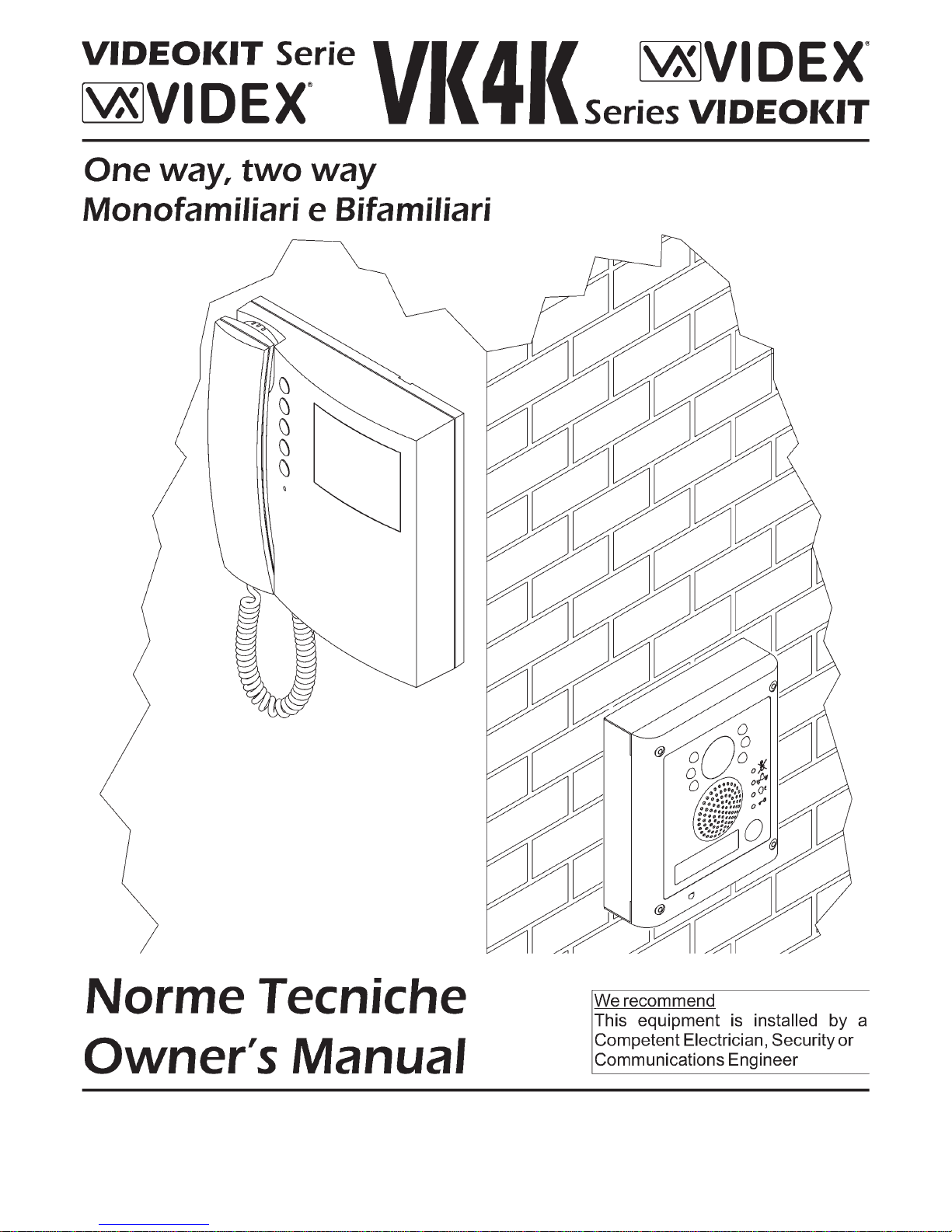
I videokit della serie VK4K fanno parte di una nuova linea che utilizza il posto
esterno con design Serie 4000. Il videocitofono fornito a corredo è Serie 3000
in una versione espressamente progettata per questa linea di videokit. L’unità
di ripresa ha le dimensioni di un modulo della Serie 4000 ed è corredato dal
relativo supporto da incasso (VK4K) o superficie (VK4K-S) in base alla
versione del kit.
Grazie all’impiego della tecnologia a microprocessore sia nel modulo portiere
elettrico - unità di ripresa che nel videocitofono, i kit di questa linea offrono
numerose funzioni innovativetra le quali troviamo:
Segnalazioni acustiche e visive in merito al funzionamento del sistema in
aiuto degli utentidiversamente abili;
Possibilità di utilizzo della serratura tramite relè a contatti puliti o scarica
capacitiva;
Possibilità di collegare un pulsante per l’apertura diretta della porta
d’ingresso;
Possibilità di programmazionedei tempi d’apertura porta econversazione;
Possibilità di collegare fino a 4 ingressi con l’ausilio di relè d’asservimento
Art.506N;
Predisposizione per il collegamento del modulo display Art.4820 e del
lettore chiavi diprossimità stand-aloneArt.4850;
Possibilità di programmare il numero di squilli da un minimo di 2 ad un
massimo di 8;
Ingresso per chiamatadi piano-locale;
Possibilità di monitorare lo stato d’apertura-chiusura della porta tramite
apposito LED presente sul videocitofono (è richiesto un conduttore
addizionale dalla portaverso il videocitofono);
Possibilità di programmare la funzione privacy da un minimo di 15 minuti ad
un massimo di8 ore;
Predisposizione per il collegamento facilitato di un citofono in parallelo (max
2 indipendentemente dalnumero di videocitofoni in parallelo);
Possibilità di collegare finoa4videocitofoni in parallelo con funzione di
intercomunicazione;
Auto-accensione selettiva incaso di più ingressi;
Brandeggio telecamera regolabile sia verticalmente che orizzontalmente
con un’escursione massimadi 10º.
Il kit comprende:
Unità di ripresa . L’unità incorpora una telecamera bianco e nero
CCD autofocus di alta qualità, i LED d’illuminazione agli infrarossi, la
circuiteria di amplificazione audio e il portiere elettrico con un pulsante di
chiamata;
Supporto da incasso ad 1 modulo (nella versione da superficie
VK4K-S questo articolo è rimpiazzato dalla relativa scatola da superficie
);
Videocitofono Bianco &Nero con schermo piattoda 4” completo
di piastra difissaggio a parete e schedadi connessione
Trasformatore di alimentazione (Cont. DIN 5 Moduli tipoA).
!
!
!
!
!
!
!
!
!
!
!
!
!
!
Nr.1 Art.4833
Nr.1 Art.4851
Art.4881
Nr.1 Art.3356
Art.3980
Nr.1 Art.850K
Come i kit VK4K e VK4K-S, ma con videocitofono a colori con
monitor TFT da3,5” e unità di ripresa con telecameraa colori
e LED d’illuminazione ademissione di luce bianca.
Art.3456
Art.4833colour
As VK4K and VK4K-S but with colour videophone with 3,5” TFT
monitor and colour camera unit with white light illumination
LEDs.
Art.3456
Art.4833colour
Come i kit VK4K e VK4K-S, ma con videocitofono bianco e nero
completo di memoria videoed alimentatore specifico .
Art.3556
Art.850K/MV
As VK4K and VK4K-S but with B&W videophone Art.3556 with memory board
and special power supply .Art.850K/MV
The VK4K series is a new range of videokits that use the 4000 series externa
l
door stationand the 3000series videophone whichis specific forthis range o
f
videokit. The camera /audiounit is the size of a single4000series module an
d
is available in eitherflush (VK4K) or surface (VK4K-S) mounting versions.
As a result of using microprocessor technology in the door panel an
d
videophone, a numberof additional features have beenadded to enhance the
operation of the videokitsand give greater feedback to the visitoranduser.
Disability friendly, visual and acoustic signals from the door panel to inform
the visitor of callstatus (call made, ringing, speak, door open).
Programmable door open andconversation time.
Expandable to 4 entrance panels (requires an additional relay Art.506N fo
r
each entrance panel).
Connections for a pushto exit button.
Two methods of operating the electric lock:- 1) through dry contact relay, 2)
using a capacitor dischargecircuit.
Facility forthe connection ofa codelock Art.4800, display module Art.4820,
stand-alone proximity reader Art. 4850 or stand-alone biometric readerArt.
4821 etc.
Programmable number of calltone rings from 2 to a maximumof8.
Input for local doorbell push button.
Programmable timed privacy function from 15 minutes to a maximum of
8
hours.
Door open status LED (additional wire required from the door to the
videophone)
Up to4 videophones can be connected in parallel, all with intercommunica
-
tion facility.
Videophones can have a maximum of two additional audio telephone
handsets connected in parallel.
Camera recallon all systems, with selective recall on systems with multiple
entrances.
Door panel camera can be adjusted horizontally and vertically (1
0
degrees).
The kit comprises of.
Camera unit Art.4833. The unit includes a high quality B&W CCD camera
with auto iris lens, infrared LEDs for illumination, audio amplifiers and one
button speaker unit;
Module front support with flush mounting box (the surface
version of the kit VK4K-S includes the relevant surface mounting bo
x
);
B&W videophone with 4” flat screen complete with mountin
g
plate and PCB connection ;
Power transformer boxed in 5 ModuleA Type DIN BOX.
!
!
!
!
!
!
!
!
!
!
!
!
!
!
1
1 Art.4851
Art.4881
1 Art.3356
Art.3980
1 Art.850K
CVK4K, CVK4K-S
Videokit Monofamiliare con videocitofono e telecamera colori
CVK4K, CVK4K-S
One way videokit with colour camera and videophone
VK4KMV, VK4KMV-S
Videokit Monofamiliare con videocitofono+memoria e telecamera bianco e nero
VK4KMV, CVK4KMV-S
One way videokit with B&W camera and videophone+memory board
VK4K, VK4K-S
Videokit Monofamiliare con videocitofono e telecamera bianco e nero
VK4K, VK4K-S
One way videokit with B&W camera and videophone
VK4K
CVK4K
VK4K/MV
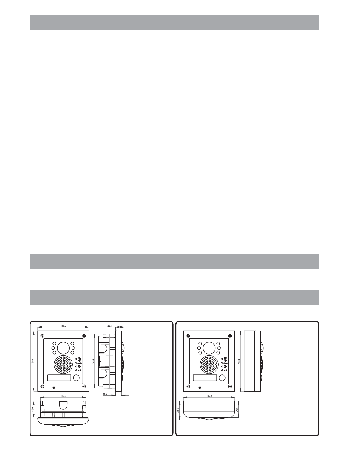
FLUSH DOOR STATION
POSTO ESTERNO DA INCASSO
SURFACE DOOR STATION
POSTO ESTERNO DA SUPERFICIE
VK4K-S
CVK4K-S
VK4K/MV-S
Page 3

3
Come i kit VK4K e VK4K-S, ma in versione bifamiliare con 2 videocitofoni
bianco e nero Art.3356, 2 trasformatori d’alimentazione Art.850K e unità di
ripresa bianco e neroa 2 pulsanti di chiamata .
Il kit comprende:
Unità di ripresa . L’unità incorpora una telecamera bianco e
nero CCD autofocus di alta qualità, i LED d’illuminazione agli infrarossi,
la circuiteriadi amplificazione audio e il portiere elettrico con 2 pulsantidi
chiamata;
Supporto da incasso ad 1 modulo (nella versione da superficie
VK4K-2S questo articolo è rimpiazzato dalla relativa scatola da
superficie );
Videocitofoni Bianco & Nero con schermo piatto da 4” completi
di (placca peril fissaggio a parete e scheda diconnessione);
Trasformatori di alimentazione (Cont. DIN 5 Moduli tipoA);
Distributore video Art.316.
Art.4833-1D
Nr.1 Art.4833-1D
Nr.1 Art.4851
Art.4881
Nr.2 Art.3356
Art.3980
Nr.2 Art.850K
Nr.1
Come i kitVK4K-2 e CVK4K-2S, macon videocitofoni a colori Art.3456 eunità
di ripresa a coloriArt.4833-1DColor.
Il videocode kit,
costituisce l’esempio della combinazione di un sistema videocitofonico con
un sistema base dicontrollo accessi.
incorporando nel posto esterno un modulo tastiera digitale,
Il kit comprende:
Unità di ripresa . L’unità incorpora una telecamera bianco e
nero CCD autofocus di alta qualità, i LED d’illuminazione agli infrarossi,
la circuiteriadi amplificazione audio e il portiere elettrico con 2 pulsantidi
chiamata;
Modulo tastiera digitale con 3 relè e 3 codici;
Supporto da incasso a 2 moduli (nella versione da superficie
VKC4K-1S questo articolo è rimpiazzato dalla relativa scatola da
superficie );
Videocitofono Bianco & Nero con schermo piatto da 4”
completo di (placca per il fissaggio a parete e scheda di
connessione);
Trasformatori di alimentazione (Cont. DIN 5 Moduli tipoA).
Nr.1 Art.4833-1
Nr.1 Art.4800
Nr.1 Art.4852
Art.4882
Nr.1 Art.3356
Art.3980
Nr.1 Art.850K
Come i kit VKC4K-1 e CVKC4K-1S ma con videocitofono a colori con display
a matrice attiva da3,5” Art.3456e con unità di ripresa a coloriArt.4833-1Color.
Come i kit VKC4K-1 e VKC4K-1S ma con 2 videocitofoni , 2
trasformatori d’alimentazione , unità di ripresa a 2 pulsanti di
chiamata e distributore video .
Art.3356
Art.850K
Art.4833-1D Art.316
Come i kit VKC4K-2 e VKC4K-2S ma con videocitofoni a colori
(display LCD a matriceattiva da 3,5”) e unità di ripresa .
Art.3456
Art.4833-1DColor
The videocode kit, including a codelock unit, which is a video door entr
y
system combined with anaccess control system.
The kit comprises of.
Camera unit . The unit includes a high quality B&W CCD
camera with auto iris lens, infrared LEDs for illumination, audio amplifier
s
and two button speakerunit;
Codelock module with 3 built-in relays and 3 codes;
Two Module front support with flush mounting box (the surface
version of the kit VKC4K-1S includes the relevant surface mounting bo
x
);
B&W videophone with 4” flat screen complete with Art.398
0
(mounting plate and pcbconnection board);
Power transformers boxed in 5 ModulesA Type DIN BOX.
1 Art.4833-1
1 Art.4800
1 Art.4852
Art.4882
1 Art.3356
1 Art.850K
As videocode kits VKC4K-1 and VKC4K-1S but using color videophone with
3,5” active matrix LCD display Art.3456 and color camera unit module
Art.4833-1 color.
As kits VKC4K-1 and VKC4K-1S but with 2 videophones , 2 powe
r
transformer , camera unit with 2 call push buttons an
d
video distributor .
Art.3356
Art.850K Art.4833-1D
Art.316
As kits VKC4K-2 and VKC4K-2S but using color videophones with
3,5 active matrix LCDdisplay and color camera unit .
Art.3456
Art.4833-1DColor
As VK4K andVK4K-S but two way versionwith2 B&W videophones Art.3356,
2 power transformers andtwo button B&W camera unit .
The kit comprises of.
Camera unit . The unit includes a high quality B&W CCD
camera with auto iris lens, infrared LEDs for illumination, audio amplifier
s
and two button speakerunit;
Two Module front support with flush mounting box (the surface
version of the kit VK4K-2S includes the relevant surface mounting bo
x
);
B&W videophones with 4” flat screen complete with Art.398
0
(mounting plate and pcbconnection board);
Power transformers boxed in 5 ModuleA Type DIN BOX;
Video distributor .
Art.4833-1D
1 Art.4833-1D
1 Art.4851
Art.4881
2 Art.3356
2 Art.850K
1 Art.316
As VK4K-2 and CVK4K-2S but with color videophones Art.3456 and colo
r
camera unit Art.4833-1DColor.
VK4K-2, VK4K-2S
Videokit bifamiliare con videocitofoni e telecamera bianco e nero
VK4K-2, VK4K-2S
Two way videokit with B&W camera and videophones
CVK4K-2, CVK4K-2S
Videokit bifamiliare con videocitofoni e telecamera a colori
CVK4K-2, CVK4K-2S
Two way videokit with color camera and videophones
VKC4K, VKC4K-S
Videocode kit monofamiliare con videocitofono e telecamera bianco e nero
VKC4K, VKC4K-S
One way videocodekit with B&W camera and videophone
CVKC4K, CVKC4K-S
Videocode kit monofamiliare con videocitofono e telecamera a colori
CVKC4K, CVKC4K-S
One way videocodekit with color camera and videophone
VKC4K-2, VKC4K-2S
Videocode kit bifamiliare con videocitofoni e telecamera bianco e nero
VKC4K-2, VKC4K-2S
Two way videocodekit with B&W camera and videophones
CVKC4K-2, CVKC4K-2S
Videocode kit bifamiliare con videocitofoni e telecamera a colori
CVKC4K-2, CVKC4K-2S
Two way videocodekit with color camera and videophones
MARKINGMARCATURA
La marcatura CE di conformità indica che il prodotto soddisfa i requisiti delle Direttive
della Comunità Economica Europea in vigore (in particolare quelle 73/23/CEE e
93/68/CEE e Compatibilità elettromagnetica 89/336) ad esso applicabili.
La marcatura CE, apposta sui prodotti dal fabbricante (o da un suo mandatario) sotto la
propria responsabilità, è stata creata con l'intento di eliminare gli ostacoli alla
circolazione dei prodotti all'interno degli Stati membri dell'Unione Europea
armonizzando diverse normative a carattere nazionale.
CE conformity marking indicates that the product respects the requirements of the
applicable European Community Directives in force (specifically 73/23/EEC, 93/68/EE
C
and the Electromagnetic Compatibility Directive 89/336).
CE marking is applied by the manufacturer (or party delegated to do so by the
manufacturer) under their own responsibility. It was created to eliminateobstacles to the
circulation of products in European Union Member States by harmonising differen
t
national standards.
Page 4
4
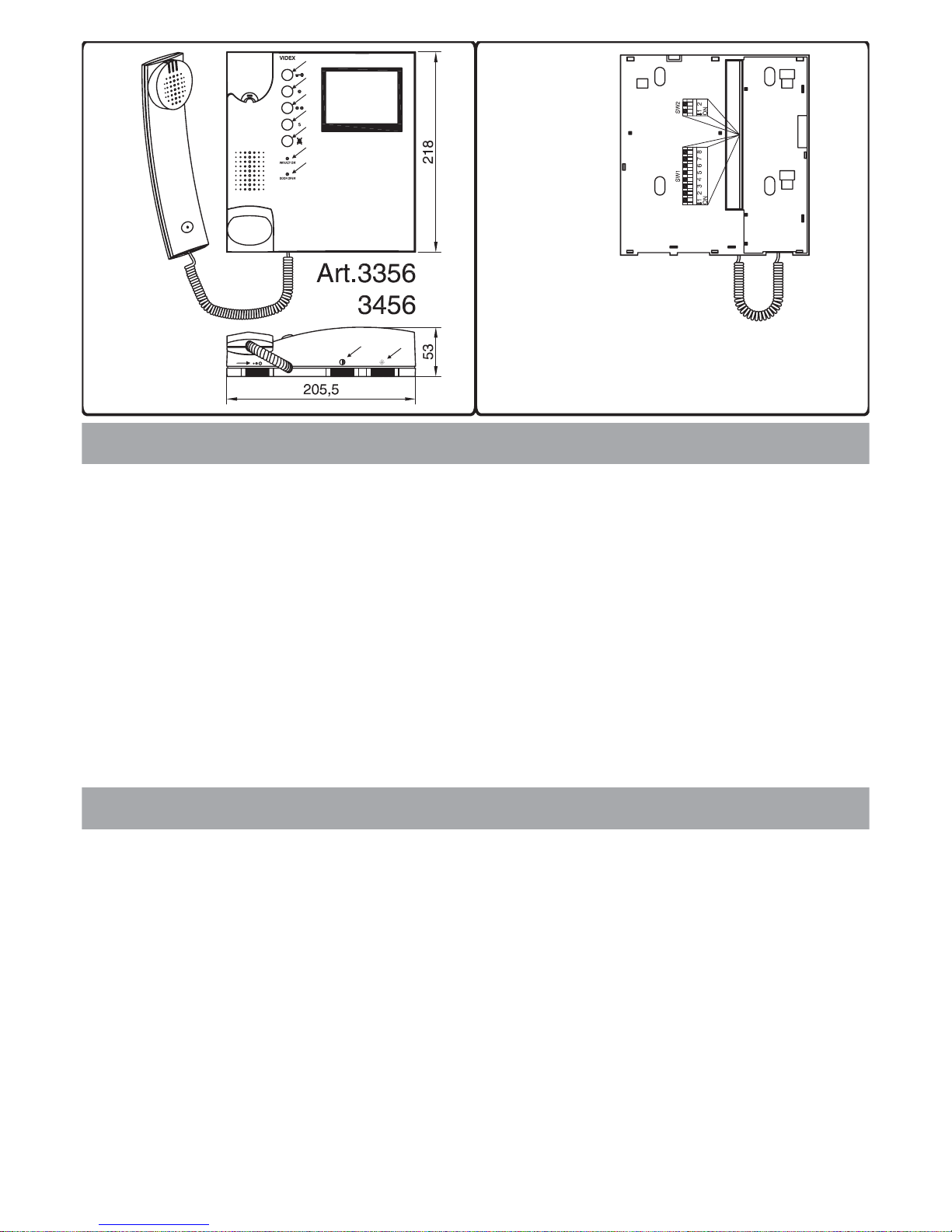
L’impostazione del videocitofono viene eseguita tramite i 2 dip-switch accessibili dalla
parte posteriore dello stesso.
OFF 1
ON 2
OFF OFF 1
ON OFF 2
OFF ON 3
ON ON 4
OFF solo tra i videocitofoni dei dueappartamenti
ON solo tra i videocitofoni dello stesso appartamento
OFF OFF 2
ON OFF 4
OFF ON 6
ON ON 8
OFF OFF 15 minuti
ON OFF 1 ora
OFF ON 4 ore
ON ON 8 ore
Il dip-switch a 2 vie serve per adattare l’impedenza del segnale video. L’impostazione di
default è “ON” per entrambi gliswitch (75 Ohm): inpresenza di più videocitofonicollegati
in parallelo (senza distributore video), gli switch devono rimanere entrambi ad “ON” solo
per l’ultimo (in ordine di connessione) videocitofono, mentre per tutti gli altri devono
essere impostati entrambi ad “OFF”.
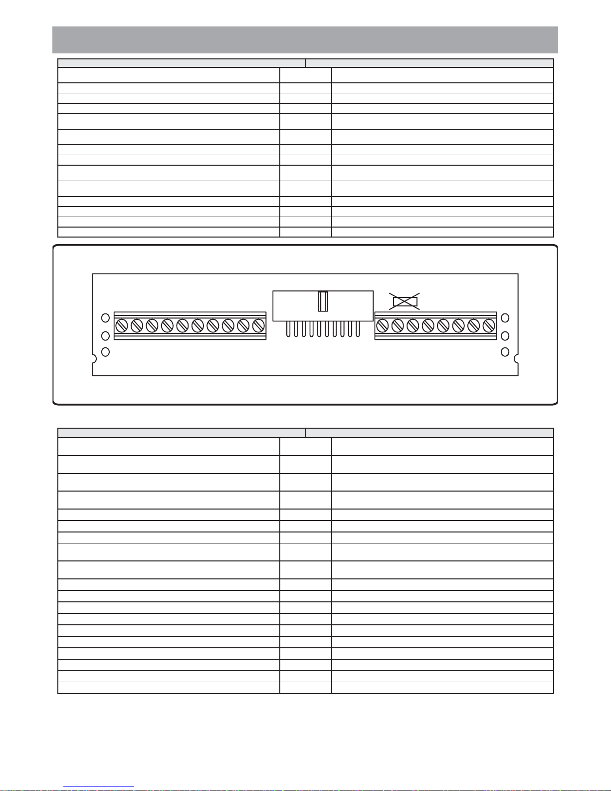
DIP-SWITCH a 8 VIE (Fig.1B SW1)
Switch 1 Indirizzo d’Appartamento
Switch 2,3 Indirizzo Interno
Switch 4 Intercomunicazione
Switch 5,6 Numero di squilli
Switch 7,8 Durata Privacy
DIP-SWITCH a 2 VIE (Fig.1B SW2)
The videophone setup is carried out by the 2 dip-switches accessible from the rear side o
f
the videophone.
OFF 1
ON 2
OFF OFF 1
ON OFF 2
OFF ON 3
ON ON 4
OFF Only between videophones of the two apartment
ON Only between videophones in the same apartment
OFF OFF 2
ON OFF 4
OFF ON 6
ON ON 8
OFF OFF 15 minutes
ON OFF 1 hours
OFF ON 4 hours
ON ON 8 hours
The two way dip-switch allows to adjust the impedance of video signal. The defaul
t
setting is “ON” for both switches (75 Ohm): when there are more videophones inparalle
l
connection (without video distributor) both switches must be “ON” only on the las
t
videophone (looking at the connection order) while for all other videophones both
switches must be set to “OFF”.
8 WAY DIP-SWITCH (Fig.1B SW1)
Switches 1 Apartment Address
Switches 2,3 Extension Address
Switch 4 Intercommunication
Switches 5,6 Number of Rings
Switches 7,8 Privacy duration time
2 WAY DIP-SWITCH (Fig.1B SW2)
IMPOSTAZIONE VIDEOCITOFONO Fig.1B VIDEOPHONE SETUP Fig.1B
Facendo riferimento alla Fig.1A vengono descritte di seguito le funzioni dei pulsanti, dei
LED e dei controlli del videocitofono.
Pulsante apri-porta/chiamata intercomunicante. Come pulsante di chiamata
intercomunicante è operativo solo quando il sistema è in stand-by. Il suo utilizzo
dipende dall’impostazione dello switch 4 dell’SW1:
Intercomunicazione solo tra appartamenti - sollevare lacornetta e premere
il pulsante chiave per chiamare il videocitofono nell’altro appartamento;
Intercomuncazione solo tra videocitofoni dello stesso appartamento sollevare la cornetta e premere il pulsante chiave 1, 2, 3 o 4 volte per
chiamare il videocitofono con indirizzo d’interno 1, 2, 3o4.
Se il videocitofono chiamatoè già in conversazione, verrà segnalato con un tono
di occupato. Se durante una conversazione intercomunicante arriva una
chiamata dall’esterno, la conversazione si interrompe per dare la precedenza
alla chiamata.
Pulsante di auto-accensione. In presenza di più ingressi, premere tante volte
quant’è il numero identificativo (1..4)del posto esternochesivuoleaccendere.
Pulsanti di servizio (morsetti 16 e 17 - morsetto comune 18).
Pulsante “privacy” ON-OFF. Il pulsante attiva/disattiva la funzione “privacy”, in
ogni caso la funzione si disattiva automaticamente allo scadere del tempo
programmato.
LED “PRIVACYON”. Accesoquando la funzione privacyèattiva.
LED “DOOR OPEN”. Fatti i necessari collegamenti, questo LED indica lo stato
d’apertura / chiusura della porta: acceso = aperta -spento=chiusa.
Regolazione del volume (3 livelli) della nota di chiamata. Il volume cresce
muovendo l’interruttore a slitta da sinistra verso destra.
Regolazione del contrasto (a sinistra per diminuire e adestraperaumentare).
Regolazione della luminosità (a sinistra per diminuire e a destraperaumentare)
Rif.a
OFF
ON
Rif.b
Rif.c,d
Rif.e
Rif.f
Rif.g
Rif.h
Rif.i
Rif.l
The functions relevant to videophone buttons, LEDs and controls are described a
s
follows (refer to Fig.1A):
Door-open / intercommunicating call button. As call button it works only when
the system is in stand-by condition. How it works as a call button depends on
the switch 4 of the SW1 (fig.1B) dip-switch:
Intercommunication only between apartments - pick up the handset an
d
press the key button one time or two to call the videophone with apartmen
t
address 1or 2.
Intercommunication only between videophones in the same apartment
-
pick upthe handset andpress the key buttonone, two, threeor four timesto cal
l
videophone with extension address 1, 2, 3 or 4.
Camera recall button. In case of more entrances, press the button 1, 2, 3 or 4
times to switch on door unit with ID 1,2,3or 4.
Service push buttons (terminal 16 and 17 - 18commonterminal).
Privacy ON-OFF button. Enable/Disable the privacy service, in any case the
service is automatically disabled when the programmed privacy timeexpire.
“PRIVACYON” LED. The LED is on whenthefunctionisenabled.
“DOOR OPEN” LED. If the required connections are done, the LED shows the
open/close status of the door: ON = Open, OFF= Closed.
Call tone volume control (3 levels). The volume increases moving the slide
switch from left to right.
Contrast control. To adjustmove from left to right.
Brightness control. To adjustmove from left to right.
Ref.a
OFF
ON
Ref.b
Ref.c,d
Ref.e
Ref.f
Ref.g
Ref.h
Ref.i
Ref.l
PULSANTI, LED E CONTROLLI Fig.1A PUSH BUTTONS, LEDs & CONTROLS Fig.1A
Fig.1A Fig.1B
a
b
c
d
e
f
g
l
i
h
Page 5
5
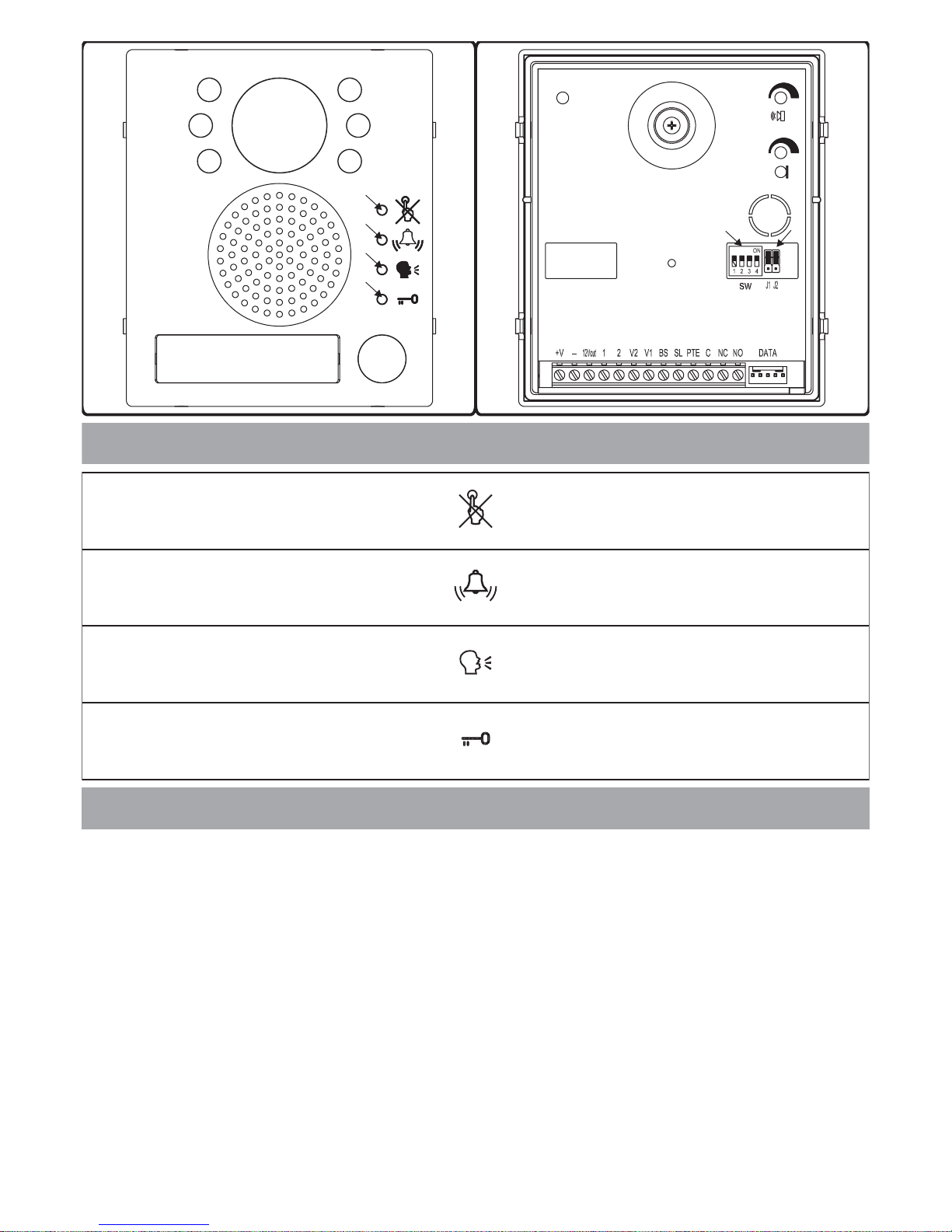
L’impostazione del portiere elettrico viene effettuata tramite il dip-switch a 4 vie ed i due
j
umpers accessibili dal retro del modulo.
I primi 2 switch permettono di configurare l’indirizzo del posto esterno: l’indirizzo è
necessario per l’auto-accensione selettiva in caso di 2 opiùpostiesterni
OFF OFF 1
ON OFF 2
OFF ON 3
ON ON 4
OFF 60 secondi
ON 120 secondi
OFF 2 secondi
ON 6 secondi
H Alto
L Basso
H Scarica capacitiva
L Contatti puliti
Quando la modalità è impostata su “scarica capacitiva”, un terminale della serratura va
collegato amassa, mentre l’altro va collegato almorsetto “NO” che fornisce una tensione
temporanea al ricevimento del comando d’apertura porta.
Nella modalitàcontatti puliti, al ricevimento delcomando d’apertura porta il contatto“NO”
chiude verso “C”.
DIP-SWITCH a 4 VIE (Fig.2B rif.a)
Switch 1,2 Indirizzo Unità
Switch 3 Tempo diConversazione
Switch 4 Tempo d’aperturaporta (J2 posizione “L”)
JUMPER J1, J2 (Fig.2B rif.b)
Posizione J1 Volume tono di conferma chiamata
Posizione J2 Funzionamentorelèapri-porta
The setup of the speaker unit is carried out through the 4 way dip-switch and the two
jumpers J1,J2 reachable from the rear side of themodule.
First two switches are used to set the speaker unit address: the speaker unit address i
s
required for camera recall operation on 2 or moreentrancessystem.
OFF OFF 1
ON OFF 2
OFF ON 3
ON ON 4
OFF 60 seconds
ON 120 seconds
OFF 2 seconds
ON 6 seconds
H High
L Low
H Capacitor discharge
L Dry contacts
When thedoor open relay operating modeis set to “capacitor discharge”,one terminal o
f
the electric lock must be connected to ground while the second must be connected to
“NO” terminal. The “NO” terminal will supply a temporary voltage when the speaker uni
t
will receive the door open command. In “dry contacts” mode the “NO” terminal i
s
internally linked to “C” terminal when the speaker unitreceivethedooropen command.
4 WAY DIP-SWITCH (Fig.2B ref.a)
Switches1,2 Unit Address
Switch 3 Conversation Time
Switch 4 Door opening time (J2=“L”position)
JUMPERS J1, J2 (Fig.2B rif.b)
J1 Position Call reassurance tone volume
J2 Position Door open relay operating mode
IMPOSTAZIONE PORTIERE ELETTRICO Fig.2B SPEAKER UNIT SETUP Fig.2B
Art.4833
H
L
Fig.2A Fig.2B
a
b
c
d
a
b
Se acceso, indica che non è possibile chiamare a causa di una
chiamata o conversazionein corso dal posto esternoin uso o da unaltro
posto esterno in caso di sistemi a più ingressi. Il LED si spegne con
l'impianto a riposo (nessunaconversazione o chiamata in corso).
When illuminated, indicatesthat it is not possible to make a callbecause
a call or a conversation is in progress (from the outdoor station from
which you are calling or from another outdoor station on systems with
multiple entrances). The LEDwill be off when the system isinstand-by.
Se acceso, indicache è in corsola chiamata dal postoesterno che si sta
utilizzando. Il LED si spegne alla risposta dell'utente chiamato o al
raggiungimento del numero disquilli programmati.
If illuminated, indicates that the call from the outdoor station is in
progress. The LEDwill switch OFF when the call isanswered or after the
programmed number of rings.
Se acceso, indica che l'utente chiamato ha risposto e la conversazione
può avere inizio. Il LED si spegne al termine della conversazione
(l'utente chiamato riaggancia la cornetta) o allo scadere del “tempo di
conversazione” programmato.
If illuminated, indicates that it is possible to speak because the call has
been answered. The LED will switch OFF at the end of a conversation
(or at the endof the conversation time).
Se acceso, indica che l'utente chiamato ha aperto la porta. Il LED resta
acceso per tutto il“tempo d'apertura porta” programmato.
If illuminated, indicates that the door lock has been operated. It will
switch OFF at the endof the programmed “door opening” time.
INDICAZIONI FORNITE DAI LED Fig.2A INFORMATION SUPPLIED BY THE LEDS Fig.2A
Rif.a
Rif.b
Rif.c
Rif.d
Ref.a
Ref.b
Ref.c
Ref.d
Page 6
6
SEGNALI PORTIERE ELETTRICO E VIDEOCITOFONO SPEAKER UNIT & VIDEOPHONE SIGNALS
SEGNALI PORTIERE ELETTRICO (FIG.2B PAG.5) SPEAKER UNIT SIGNALS (FIG.2B PAG.5)
Descrizione
Mo rsetto
Terminal
Description
Ingresso d alimentazione 16÷20Vdc
+V
Power input 16÷20Vdc
Alimentazione riferimento di massa
-
Power input ground
Uscita 12Vdc. 0,3A max. per alimentazione accessori
12Vout
12Vdc. 0,3A max. output to supply accessiories
Ingresso fonia verso l altoparlante del portiele elettrico e segnale
dati (12V circa in stand-by, 5V circa in conversazione)
1
Speech line input toward the loudspeaker and data signal (about
12V in stand-by, about 5V with a conversation in progress)
Uscita fonia dal microfono del portiere elettrico (12V circa in
stand-by, 3V circa in conversazione)
2
Speech line output from the microphone (about 12V in stand-by,
about 3V with a conversation in progress)
Uscita segnale video bilanciato sinc.-
V1
Balanced video signal sync.-
Uscita segnale video bilanciato sinc.+
V2
Balanced video signal sync.+
Ingresso/Uscita segnale di linea occupata (12Vcirca in stand-by,
0V circa con chiamata in corso)
BS
Input/Output busy signal (about 12V in stand-by, about 0V with a
call in progress)
Uscita segnale per attivazione relè scambio video (attivo basso
con chiamata in corso)
SL
Active low output to enable the enslavement relay for video signal exchange (active with a call in progress)
Ingresso attivo basso di comando diretto per il relè apri-porta
PTE
Active low input to control directly the door open relay
Relè apri-porta contatto comune
C
Door open relay common contact
Relè apri-porta contatto normalmente chiuso
NC
Door open relay normally closed contact
Relè apri-porta contatto normalmente aperto
NO
Door open relay normally open contact
*
Remove R1 resistor
Rimuovere la resistenza R1
R1
*
1
2
3
4
5
6
7
8
9
10
11
12
13
14
15
16
17
18
Scheda di connessione videocitofono Art.3980 Art.3980 Videophone Connection Board
SEGNALI VIDEOCITOFONO (FIG.3) VIDEOPHONE SIGNALS (FIG.3)
Descrizione
Morsetto
Terminal
Description
Uscita fonia proveniente dal microfono della cornetta e segnale
dati (12V circa in stand-by, 5V circa in conversazione)
1
Speech line output from handset s microphone and data signal
(About 12V in stand-by, about 5V in conversation)
Ingresso fonia verso l altoparlante della cornetta (12V circa in
stand-by, 3V circa in conversazione)
2
Speech line input toward the handset s loudspeaker (About 12V
in stand-by, about 3V in conversation)
Ingresso fonia verso l altoparlante del citofono collegato in parallelo (12V circa in stand-by e 3V circa in conversazione)
3
Speech line input toward the loudspeaker of the parallel telephone (About 12V in stand-by, about 3V in conversation)
Segnale video bilanciato 1 sinc.-
4
Balanced video signal 1 sync.-
Segnale video bilanciato 2 sinc.+
5
Balanced video signal 2 sync.+
Ingresso d alimentazione riferimento di massa
6
Power supply ground input
Ingresso d alimentazione 12Vdc 150mA per videocitofono con
memoria video (solo per il videocitofono 3556)
7
12Vdc 150mA power input to supply memory board, only on
3556 videophone
Ingresso/Uscita 20Vdc (come ingresso 16÷20Vdc 0,5A come
uscita 20Vdc 0,5A max)
8
20Vdc Input/Output (As input 16÷20Vdc 0,5A as output 20Vdc
0,5A max)
Ingresso d alimentazione 24Vac 1A max
9
24Vac 1A max power input
Ingresso d alimentazione 0Vac
10
0Vac power input
Uscita riferimento di massa citofono in parallelo
11
Output ground for parallel telephone
Uscita tono di chiamata per citofono in parallelo
12
Output call tone for parallel telephone
Ingresso comando apri-porta citofono in parallelo
13
Input for door-open command from parallel telephone
Ingresso 12Vdc per LED di segnalazione porta aperta
14
12Vdc input for door-open LED
Ingresso per chiamata locale (5V stand by, 0V in funzione)
15
Local call input
Contatto pulsante S riferito al morsetto 18
16
S button contact referred to terminal 18
Contatto pulsante !! riferito al morsetto 18
17
!! button contact referred to terminal 18
Contatto comune pulsanti S e !!
18
Common contact for S and !! buttons
Fig.3
Page 7

7
Art.3356, 3456 e 3556
Istruzioni di montaggio
Art.3356, 3456 e 3556
Mounting instructions
A
B
B
B
B
D
E
E
E
E
F
fig.4
G
H
C
fig.5
I
L
A
M
F
N
N
N
N
O
Piano terra finito
Finished Floor
Piastra di fissaggio Videocitofono
Mounting Plate
135cm
Quote in cm
Size in cm
fig.6
A
Mounting plate installation and PCB
connections
Installing the Videophone onto mounting plate
!
!
!
!
!
!
!
!
Place the mounting plate against the wall a
s
shown in (135cm from floor level); an
d
mark the fixing holes for the four wall plugs
( ) and for the back box if used ( )
which must be flushed into the wall in line with
the opening as shown in .
Once the back box is flushed into the wall (if used), drill the fou
r
fixing holes and insert the wall plugs . Thread the cables through
the opening and fix the mounting plate to the wall with the 4
screws ( ), using aPhilips screwdriver.
Fit the PCB against the mounting plate as shown in ; inser
t
the wires (As short as possible) into terminals . Secure them
using a terminalscrewdriver.
Unclip the PCB ( ), rotate it 90º anticlockwise and fit it into it
s
housing as shownin .
As shown in , move the videophone close to the mountin
g
plate so thatthe ribbon cable will reachthe connector .
As shown in , connect the female plug on the ribbon cable
I
coming from the videophone to the male plug connector on the
PCB .
Place the videophone against the4 hooks on themounting plate
and push down: the videophone will automatically lock into place
using clasp as shown in .
To remove the videophone from the wall, push the clasp in the
direction of thewall with a screwdriverand at the sametime push the
videophone upwards.
We recommend using a back box in order to contain excess wire
behind the backplate.
The wires must be connected to the terminals as shown on the
relevant wiring diagrams.
A
fig.6
B
fig.4 C fig.4
D fig.4
C
B
DA
E fig.4
F A fig.4
G-H
F fig.4
fig.5
fig.5 L
AI
fig.5
M
F
LN
A
O fig.5
O
Notes
(1)
(2)
(1)
(2)
Applicazione a muro della piastra di
fissaggio e collegamenti scheda di
connessione
Applicazione del Videocitofono alla piastra
!
!
!
!
!
!
!
!
Appoggiare al muro la piastra di fissaggio
come indicato in (135cm da terra);
prendere i riferimenti dei quattro fori per
l’inserimento dei 4 tasselli ad espansione
( ) e, nel caso si impieghi, prendere il
riferimento per la scatola da incasso ( ), che dovrà essere
murata in posizione centrale rispetto all’apertura al fine di
agevolare il passaggiodei fili come mostrato in .
Murare (se impiegata) la scatola da incasso , eseguire i 4 fori ed
inserire i tasselli ad espansione . Passare i cavi nell’apertura e
fissare la piastra con le 4 viti ( ) utilizzando un cacciavite a
croce.
Appoggiare la scheda di connessione sulla piastra come
mostrato in ; inserire i fili (che devono essere più corti
possibile) nelle morsettiere ed e serrare con un cacciavite a
taglio.
Fissati i fili, sfilare la scheda di connessione ( ), ruotarla di 90º
in senso antiorario ed infilarla nella propria sede come mostrato i n
.
Avvicinare, come da , il videocitofono alla piastra per
agevolare la connessionedel flat .
Come mostrato in inserire il connettore del flat , che fuoriesce
dalla parte posteriore del videocitofono, nel connettore della
scheda di connessione .
Facendo corrispondere le 4 fessure presenti sulla base del
videocitofono con i 4 incastri della piastra , appoggiare il video
sulla piastra e spingerlo verso il basso fino allo scatto, compiendo
un movimento comemostrato dalle frecce in .
Per rimuovere il videocitofono, spingere con un cacciavite a taglio il
dente verso il muro e, contemporaneamente, tirare il videocitofono verso l’alto.
Si consiglia diutilizzare una scatola da incasso(non in dotazione) al
fine di contenerel’eventuale lunghezza eccedente dei fili.
I collegamenti alla morsettiera devono essere eseguiti rispettando
gli schemi forniti a corredo del videocitofono, per applicazioni
differenti da quelle degli schemi standard, rivolgersi al proprio
rivenditore.
A
fig.6
B
fig.4
C fig.4
D
fig.4
C
BD
A E fig.4
FA
fig.4
GH
F fig.4
fig.5
fig.5 L A
I
fig.5 I
M
F
LNA
fig.5
O
Note
(1)
(2)
(1)
(2)
Page 8

8
POSTO ESTERNO DA SUPERFICIE
POSTO ESTERNO DA INCASSO
Note
1. Appoggiare la scatola da superficie alla parete lasciando circa 165-170cm
tra la parte alta della scatola ed il terreno come mostrato in figura 1 quindi
prendere i riferimenti per i fori di fissaggio tenendo presente che il gruppo
di fili (fig.2) deve passare attraverso l’apertura presente sulla scatola
da superficie.
;
2. Come mostrato in figura 2, realizzare i fori di fissaggio , inserire al loro
interno i tasselliad espansione e, facendo passare i fili dicollegamento
attraverso l’apertura , fissare la scatola da superficie alla parete
utilizzando le viti ;
3. Inserire ilmodulo nel supporto come mostrato in figura 3;
4. Prima di agganciare alla scatola da superficie il supporto completo di
modulo, inserire i fermianti-effrazione come mostratoin figura 4;
5. Muovendo il supporto come mostrato dalle frecce di figura 5, procedere
all’aggancio dello stesso alla scatola da superficie . Il perno deve
inserirsi nel relativo alloggiamento come mostratoinfigura 6;
6. Come mostrato in figura 7, tirare il supporto moduli indietro compiendo
contemporaneamente un leggero movimento a sinistra come suggerito
dalle frecce;
7. Come mostrato in figura 8, ruotare il supporto moduli nella direzione
consigliata dalla freccia e provvedere ad agganciare il fermo
all’alloggiamento del perno. Assicurato il supporto alla scatola da
superficie, svolgere le seguentioperazioni:
7b.effettuare i necessari collegamenti con l’ausilio del giravite (lato piatto
della lama) fornito acorredo;
7c.regolare l’angolo di ripresa della telecamera agendosullavite ;
8. Ad impianto testato e funzionante, procedendo a ritroso delicatamente,
chiudere e fissareil supporto moduli allascatola da superficie utilizzandoil
giravite (lato torx della lama) e le viti come mostrato in figura 9.
Se il posto esternoè da incasso occorre procedere come diseguitoindicato:
1. Dopo aver opportunamente protetto i fori di fissaggio per il supporto
moduli, murare la scatola da incasso ad una altezza tale da avere circa
165-170cm tra la parte alta della scatola e il terreno avendo cura di far
passare il gruppo di fili (fig.2) attraverso uno dei fori precedentemente
aperti sul fondo della scatola.
;
2. Proseguire dal passo 3 della installazione da superficie tenendo presente
che al punto 7il fermo va agganciatocome mostrato in figura 10.
La lama del giravite fornito a corredo ha due punte, una piatta ed una torx.
Sfilare la punta ereinserirla nel manico scegliendo il latodesiderato.
ed
a
be
dc
f
gh
i
h
cl
m
h
h
n
m
p
sq
e
n
Se non indicato, il verso di montaggio della scatola deve
essere tale da farrimanere la cerniera sulla sinistra
Se non indicato sul fondo della scatola, il
verso di muratura deve essere tale da lasciare la cerniera sulla sinistra.
Fare attenzione affinché la scatolasia murata a filo muro finito
Nota
bene: non serrare leviti più del necessario.
!
7a.eseguire le opportune configurazioni dell’unità tramite i 2 jumper ed il
dip-switch a 4 vieaccessibili dall’apertura o
La realizzazione dell’impianto deve essere eseguitanel rispetto delle
vigenti normative nazionali,in particolare si raccomanda di:
Collegare l’impianto alla rete elettrica tramite un
che abbia una distanza di separazione
del contatto di almeno 3mm per ciascun polo e che sia in grado di
disconnettere tutti ipoli simultaneamente;
Il deve essere
posizionato in un luogo tale da consentirne un facile accesso in
caso di necessità.
Rimuovere i coperchi copri-morsetti svitando le relative viti e
tirandoli verso l’alto;
Fissare l’alimentatore su barra DIN o direttamente a parete
utilizzando le vitied i relativi tasselli adespansione forniti a corredo;
Togliere la tensione di rete tramite il dispositivo sopra indicato ed
eseguire le connessioni come previsto dagli schemi proposti (la
connessione verso la rete va effettuata in base alla tensione
disponibile 127 o230Vac).
Verificare che non vi siano errori di connessione e che i fili siano
ben serrati neimorsetti;
Inserire a scattoi coperchi copri-morsetti efissarli tramite le relative
viti;
Eseguiti tutti i collegamenti, dare tensione all’impianto.
!
!
!
!
!
!
!
!
dispositivo di
interruzione omnipolare
dispositivo di interruzione omnipolare
Installazione dell’alimentatore
SURFACE DOOR STATION
FLUSH DOOR STATION
Notes
1. Place the surface box against the wall (165-170cm between the top of the
box and the floor lever asshow in figure 1) and mark thefixing holes for the
wall plugs and hole for the cables (fig.2).
;
2. As shownon figure 2, drill the fixingholes , insert the wall plugs and fee
d
the cables through thesurface box opening , fixsurface box to the wal
l
using the screws ;
3. Hook themodule in the support frame as shown in figure 3;
4. Before the installation of the module support frame, fit the two anti
-
tampering locks provided asshown in figure 4;
5. As shown in figure 5, hook the module support frame (complete with
modules) to surface box moving the frame as suggested from pointers.
Ensure that the pivot (fig.5) goes inside the relevanthousing as shown
in figure 6.
6. As shown in figure 7, pull back the module support frame while moving i
t
slightly to the leftas suggested by the pointers;
7. As shown in figure 8, open the module support frame as suggested b
y
the pointer, hook the hinge lock to the hinge . When the support frame
is hooked to thesurface box, do the following operations:
7a.make the required settings operating the two jumpers and the 4 wa
y
dip-switch accessible from theopening (fig.8)
7b.make the required connections using the screwdriver provided (blade
flat side);
7c.adjust the camera viewing angle by operatingthescrew (fig.8);
8. When the system has been tested and is working correctly, move back the
module support frame carefully, fix it to the surface box using the provide
d
screwdriver (blade torx side) and the pin machine torx screws a
s
shown in figure 9.
If the door stationis a flush, carry out the following:
1. Protect the module support frame fixing holes from dust then embed the
back boxinto the wall(165-170cm between thetop of the box and the floo
r
level as shown on the figure 1) feeding the cables (fig.2) through a
previous opened hole in the box.
2. Continue from step 3 of surfacemounting, but at step 6hook the hinge loc
k
as shown on figure10.
The screwdriver’s blade has two sides, one flat and one torx, to select one
of them unplug the blade from the screwdriver body and plug it into the
required side.
e
ab
edc
f
gh
h
c
lm
h
h
nm
o
p
sq
e
n
Observe the orientation of the
box with the hingeon the left
Note: do not over tighten the screws more than is
necessary.
Observe the direction of the bo
x
ensuring the hingeis on the leftand take care thatthe box profile is in
line with the finishedwall profile;
!
The system must be installed according to national rules in force, in
particular we recommendto:
Connect the system to the mains through an
which shall have contact separation of at least 3mm in
each pole andshall disconnect all poles simultaneously;
The shall be placed for easy access an
d
the switch shall remain readily operable.
Remove the terminal side covers by unscrewing the retainin
g
screws;
Fix the power supply to a DIN bar or directly to the wall using two
expansion type screws;
Switch off the mains using the circuit breaker mentioned above an
d
then make the connections as shown on theinstallation diagrams;
Check the connectionsand secure the wires intothe terminals;
Replace the terminal covers and fix them using the relevan
t
screws;
When all connectionsare made, restore the mains.
!
!
all-pole circui
t
breaker
all-pole circuit breaker
Power Supply Installation
!
!
!
!
!
!
COLLEGAMENTO ALLA RETE ELETTRICA ED
INSTALLAZIONE ALIMENTATORE
CONNECTION TO MAINS AND POWER SUPPLY
MOUNTING INSTRUCTIONS
INSTALLAZIONE POSTO ESTERNO DOOR STATION MOUNTING
Page 9

9
Page 10

10
In caso di malfunzionamenti effettuare iseguenticontrollipreliminari:
Verificare che i conduttori siano collegati in accordo a quanto indicato nello schema
d’istallazione e che questi siano saldamente serrati nei morsetti (videocitofono,
portiere elettrico o alimentatore);
Verificare che sia presente la tensione di rete tra i morsetti 230Vac (o 127Vac)e0del
trasformatore di alimentazioneArt.850K;
Verificare la presenza della tensione “24Vac” in uscita dal trasformatore Art.850K.
L’eventuale assenza di tensione può essere causata dall’interruzione del fusibile da
1,6A, in tal caso toglierela tensione direte, accertarsi che non vi siano sovraccarichio
cortocircuiti e sostituire il fusibile con uno uguale oequivalente;
Verificare che la tensione fra i morsetti “ ”e“ ” del portiere elettrico sia compresa tra 16
e 20Vdc;
Se il problema non è tra quelli sopra indicati,consultarelaseguentetabella.
!
!
!
! +-
In case of system failure, do the following aspreliminarychecks:
Check that the cables are connected as shown in the installation diagram and that the
cables are firmly fixed into the relevant terminals;
Check thatthe mains voltageis available onterminals 230Vac(or 127Vac) and 0 ofthe
power transformer Art.850K;
Check the 24Vac voltage outputof the power transformer Art.850K. If this voltage is no
t
available it could be the 1,6A fuse, in this case remove the mains voltage, remove
possible short-circuits or overload sources then replace the fuse with an equal o
r
equivalent one.
Check that the voltage between theterminals “ ” and “ ” of the speakerunit is between
16 and 20Vdc.
If the problem is not listed above, look atthefollowingtable.
!
!
!
!
+-
RICERCA GUASTI TROUBLESHOOTING GUIDE
L’Art.4833 (posto esterno) non
riesce a far squillare l’interno (il
LED campana si accende per
circa 2 secondi):
The Art.4833 (door station) is not
able to call the extension (the
bell LED is switched on for 2
seconds):
Durante la conversazione non si
riesce ad aprire la porta, ma il
LED chiave dell’Art.4833 si
accende:
During the conversation it is not
possible to open the door but the
key LED (Art.4833) switches on
for the programmed time:
Rumore di fondo durante la
conversazione:
Noise over the speech line
during the conversation:
Non funziona il servizio di “autoaccensione”:
Camera recall service does not
work:
Non funziona la chiamata
intercomunicante:
Intercommunicating call does not
work:
L’immagine mostrata dal monitor
del videocitofono è distorta o
riflessa:
The video shown on the monitor
is of a bad quality and the image
is distorted or double
Durante la conversazione non è
possibile aprire la porta:
During the conversation it is not
possible to open the door:
La fonia va dal posto esterno
verso l’interno ma non viceversa:
Speech only from outside to
inside:
Volume audio di conversazione
non adeguato:
Low volume of speech:
Non funziona la chiamata di
piano:
Local call does not work:
La chiamata dal posto esterno
funziona correttamente, ma alla
risposta cade la comunicazione:
External call works but when
answered the communication
fails:
!
!
!
Errato collegamento dei fili tra
l’Art.4833 e l’Art.3356,
verificare in particolare il filo
audio/dati “1”.
Sezione dei fili inadeguata.
L’indirizzo programmato sul
dip-switch dell’Art.3356 non è
corretto.
!
!
!
Wrong connection between
Art.4833 and 3356.
Wires section unsuitable.
Programmed videophone
address incorrect.
!
!
!
Ponticello mobile J2 in
posizione errata.
Fili della serratura collegati in
maniera errata.
Tipologia della serratura non
adatta.
!
!
!
Incorrect position of J2 jumper.
Electric lock wires
unconnected or in short.
Wrong electric lock type.
!
!
I 6 fili comuni sono stati
canalizzati insieme a cavi di
rete a 230 o 380Vac.
I fili di alimentazione 24Vac del
videocitofono Art.3356 sono
stati canalizzati insieme ai 6 fili
comuni per un tratto troppo
lungo.
!
!
6 common wires cabled
together with 230 or 380Vac
power lines.
6 common wires cabled
together with 24Vac
videophone power supply
wires.
! Premuto il tasto “auto-
accensione” per un numero di
volte diverso dall’ID del posto
esterno da accendere.
! Camera recall button pressed
for a number of times different
from the ID of the door station
to be switched on.
! Premuto il tasto “chiave” per
un numero di volte diverso
dall’indirizzo del videocitofono
da chiamare.
! ”Key” button pressed for a
number of times different from
the videophone address value.
!
!
!
Segnali V1 e V2 non connessi,
scambiati o in corto circuito.
Gli switch del dip-switch a 2
vie del’ultimo videocitofono
non sono entrambi ad ON.
Se presente l’Art.316, linee
passanti V1 e V2 non chiuse.
!
!
!
V1,V2 signals unconnected,
exchanged or put in short.
The switches of the two way
dip-switch are not both in ON
position.
V1,V2 of the last Art.316 (if
present) not closed with 75
Ohm resistor.
! Sezione dei fili inadeguata. ! Wires section unsuitable.
! Filo “ ” interrotto o in corto
circuito.
2 ! Wire “ ” broken or in short.2
! Trimmer di regolazione volume
dell’Art.4833 impostati in modo
non appropriato.
! Volume trimmers of Art.4833
require adjustment.
! Connessione errata o pulsante
difettoso.
! Wrong connection or call
button broken.
! Sezione dei fili inadeguata. ! Wires section unsuitable.
!
!
!
Verificare la connessione dei 6
fili comuni e rimuovere
eventuali cortocircuiti.
Aumentare la sezione dei fili o
raddoppiarla utilizzandone altri
disponibili.
Verificare l’indirizzo del
videocitofono.
!
!
!
Check 6 common wires
connections especially wire “ ”
(speech line/data).
Use wires with a larger section
or double section using two
wires for each signal.
Check videophone address.
1
!
!
!
Verificare sull’Art.4833 la
posizione del ponticello J2.
Verificare il collegamento dei
fili.
Verificare che la tipologia di
alimentazione della serratura
(ac o dc) corrisponda
all’impostazione di J2.
!
!
!
Check J2 position on the
Art.4833.
Check wires connection.
Check that the electric lock
type (ac or dc) is suitable for
the J2 position chosen.
!
!
Isolare i 6 fili comuni da cavi di
rete o altri cavi ad alta
tensione.
Canalizzare i fili
d’alimentazione del
videocitofono separatamente
dai 6 fili comuni o insieme per
un tratto più breve.
!
!
Separate the 6 common wires
from the high voltages cables.
Separate the 6 common wires
from the two 24Vac wires or
cable them together only for a
short distance.
! Verificare il valore dell’ID del
posto esterno (1..4) e premere
il pulsante di “autoaccensione” tante volte
quant’è il valore dell’ID.
! Check the ID (1..4) of the door
station to be recalled and
press the camera recall button
as many time as the ID value.
! Verificare la corretta
impostazione degli indirizzi dei
videocitofoni.
! Check the address of the
videophone you are calling
and try again.
!
!
!
Verificare continuità ed
isolamento dei fili V1,V2
Mettere ad on entrambi gli
switch.
Chiudere le linee passanti
V1,V2 verso massa con le
resistenze fornite a corredo
!
!
!
Check that the wires are not
broken and isolated.
Set both switches in ON
position.
Close through V1,V2 of the
Art.316 toward the ground with
provided resistors.
! Aumentare la sezione dei fili o
raddoppiarla utilizzandone altri
disponibili.
! Use wires with a larger section
or double section using two
wires for each signal.
! Controllare il collegamento del
filo “ ”.2
! Check connection of wire “ ”.2
! Regolare opportunamente i
trimmer fino a raggiungere il
livello di volume desiderato.
! Adjust the trimmers until the
required volume is reached.
! Controllare la connessione o
sostituire il pulsante.
! Check connection or replace
the button.
! Aumentare la sezione dei fili o
raddoppiarla utilizzandone altri
disponibili.
! Use wires with a larger section
or double section using two
wires for each signal.
Sintomo SymptomCausa CauseSoluzione Solution
FILI E SEZIONI SECTION OF WIRES
NOTA IMPORTANTE
Per le connessioni Video e quelle audio suggeriamo di utilizzare delle coppie di fili
intrecciati: una coppia per la linea video (morsetti “ ” e “ ”, segnali “ ” e “ ”) ed una
coppia per quella audio (morsetti “ ”e “ ”, segnali “ ”e “ ”).
2 fili da 1 mm
fino a 50m : tutti i fili da 0.35 mm .
da 50 a 100m : fili + e - da 0.75 mm ; tutti gli altri da 0.5 mm .
da 100 a 200m : fili + e - da 1.5 mm ; tutti gli altri da 0.75 mm .
fino a 50m : fili+ e - da 0.5 mm ; tutti gli altri 0.35 mm .
da 50 a 100m : fili + e - da 1 mm ; tutti glialtri0.5mm .
da 100 a 200m : fili + e - da 2 mm ; tutti gli altri0.75mm .
4 5 V1 V2
12 12
Dal trasformatore al videocitofono max 20 mt.:
Dal videocitofono al posto esterno:
per VK4K, VKC4K
per il CVK4K
2
2
22
22
22
22
22
IMPORTANT NOTE
Video connections and Audio connections must be wired in twisted pair : pair the video
lines (terminals “ ” and “ ” signals “ ” and “ ”), pair the audio lines (terminals “ ” an
d
“ ”signals“ ” and“ ”).
2 wires 1 mm .
up to 50 mt : allwires 0.35 mm .
from 50 to 100mt : wires+ and – 0.75 mm ; other wires 0.5mm .
from 100 to 200mt :wires + and – 1.5 mm ; other wires0.75mm
up to 50 mt : wires+ and – 0.5 mm ;othercables0.35 mm .
from 50 to 100mt : wires+ and – 1 mm ; other cables 0.5mm .
from 100to 200 mt : wires +and–2 mm ; other cables 0.75 mm .
4 5 V1 V2 1
212
Between transformer and videophone 20 mt max:
Between videophone and outdoor station:
For VK4K, VKC4K
For CVK4K
2
2
22
22
22
22
22
Page 11

11
!
!
!
Tutti gli schemi, anche se non espressamente indicato, si riferiscono alle versioni da incasso o superficie, bianco e nero o colori dei
relativi kit.
Le connessioni tratteggiate si riferiscono a collegamenti facoltativi
(“Local bell”, “Push to exit” e “Door monitor”).
Alcuni schemi mostrano indicazioni per il collegamento di
serrature 12Vdc: tali indicazioni sono da ritenersi valide per ogni
schema del presentemanuale.
12 Lo schema mostra l’installazionedi un videokitmonofamiliare
ed il collegamento di un citofono ed una suoneria addizionali.
13 Lo schema mostra l’installazione di un videocode kit monofa-
miliare. Questo tipo di kit abbina le prestazioni di un videokit
alle funzioni offerte dalle tastiere digitali VIDEX: l’utente,
digitando il proprio codice d’accesso, può aprire la porta
d’ingresso dall’esterno.
14 Lo schema mostra l’installazionedi un videokitmonofamiliare
con l’aggiunta di un secondo posto esterno per la realizzazione di un sistema a 2 ingressi.
15 Lo schema mostra l’installazionedi un videokitmonofamiliare
con l’aggiunta di 3 videocitofoni per la realizzazione di un
sistema intercomunicante.
16 Lo schema mostra un videokit monofamiliare
con esempi di applicazioni dei pulsanti di servizio e il
collegamento di un videocifono addizionale senza l’utilizzo
del distributore video Art.316.
17 Lo schema mostra l’installazionedi un videokit bifamiliare.
18 Lo schema mostra l’installazione diun videokit bifamiliare con
l’aggiunta di un secondo posto esterno per la realizzazione di
un sistema a 2 ingressi.
DESCRIZIONE SCHEMI
Pagina Descrizione
Le connessioni mostrate per il citofono e la suoneria
addizionali sono valide per tutti gli altri schemi del
manuale.
Da notare l’utilizzo del relè
Art.506N per commutare il segnale video tra i 2 ingressi e
l’impostazione di un diverso indirizzo per ciascuno dei 2
posti esterni.
Da notare l’utilizzo dell’Art.316
per la distribuzione del segnale video e l’impostazione
del dip-switch ad 8 video di ciascun videocitofono:
switch 1 ad OFF e switch 4 ad ON ad indicare
l’appartamento 1 e l’intercomunicazione tra videocitofoni dello stesso appartamento mentre gli switch 2 e 3
indicano il numero (1..4) di interno.
Da notare la configurazione
del dip-switch a 2 vie di ciascun videocitofono: per il
primo (in ordine di collegamento) entrambi gli switch
sono ad OFF, mentre nel secondo sonoentrambi ad ON.
Da
notare l’utilizzo del distributore video Art.316 e la
configurazione del dip-switch ad 8 vie dei due videocitofoni: switch 1 ad OFF per il videocitofono
nell’appartamento 1, ad ON per il videocitofono
nell’appartamento 2 e switch 4 ad OFF per entrambi ad
indicare intercomunicazione tra appartamenti.
l’installazione
19 Lo schema mostra l’installazione diun videokit bifamiliare con
l’aggiunta di 3 posti esterni per la realizzazione di un sistema
a 4 ingressi.
Da notare l’utilizzo del relè
Art.506N per commutare il segnale video tra i 2 ingressi e
l’impostazione di un diverso indirizzo per ciascuno dei 2
posti esterni.
Da notare la configurazione degli indirizzi dei
posti esterni (dip-switch a 4 vie switch 1 e 2) e l’utilizzo
degli Art.506N per la commutazione del segnale video tra
i 4 ingressi.
!
!
!
All diagrams referto all kits versions: flush or surface,color or blac
k
& white.
Dashed connections refer to optional connections (
).
Some diagrams show how to connect a 12Vdc electric lock: these
directions are suitablefor all diagrams in thismanual.
12 The diagram shows the installation of one way videokit with
additional intercom and extension sounder.
13 The diagram shows the installation of one way videocode kit.
This videocode kit adds the features offered by a VIDE
X
digital codelock: the user can open the door from outside b
y
entering the relevantaccess code on the keypad.
14 The diagram shows the installation of one way videokit with
the addition of a second door station to make a 2 entrance
system.
15 The diagram shows the installation of one way videokit with
3
additional videophones to make an intercommunicatin
g
system.
16 The diagrams shows the installation of one way videokit with
example of how to use the service push button and how to
connect an additional videophone without using the video
distributor Art.316.
17 The diagram shows the installation of a two way videokit.
18 The diagram shows the installation of a two way videokit with
the addition of a second door station to make a two entrance
system.
19 The diagram shows the installation of a two way videokit with
3 additional door stations to make a 4 entrance system.
DIAGRAMS DESCRIPTION
Page Description
Connections
shown for the intercom and the sounder are suitable fo
r
all diagrams in this manual.
Note the use of the relay Art.506N to switch the
video signal between the two door stations and the
different address set foreach door station.
Note the use of the Art.316 to distribute the video
signal and the setup of the 8 way dip-switch of each
videophone: switch 1 OFF and switch 4 ON to point ou
t
flat 1 and intercommunication within the same flat while
switches 2 and 3 set the extension address(1..4).
Note the setup of the 2 way dip-switch
of each videophone: both switches OFF for the firs
t
videophone following the connection order, both
switches ON for the second videophone (the last).
Note the use of video distributor Art.316 and the setup o
f
the 8 way dip-switch of each videophone: switch 1 OF
F
for the videophone in flat 1, switch 1 ON for the
videophone in the flat 2, switch 4 OFF for both
videophones to set intercommunication between two
flats.
Note the use of the relay Art.506N to switch the
video signal between the two door stations and the
different address set foreach door station.
Note
the different address set for each door station (1..4) an
d
the use of the Art.506N to switch the video signa
l
between the 4 door stations.
“Local bell”,
“Push to exit” & “Door monitor”
SCHEMI D’INSTALLAZIONE
NOTE E SUGGERIMENTI
INSTALLATION DIAGRAMS
NOTES & SUGGESTIONS
Page 12

12
Page 13

13
Page 14

14
Page 15

15
Page 16

16
Page 17

17
Page 18

18
Page 19

19
Page 20

Main UK office
VIDEX SECURITY LTD
1 Osprey
Trinity Park Trinity Way
London E4 8TD
Phone: +44 0870 3001240
Fax: +44 208 - 5235825
www.videx-security.com
e-mail: info@videx-security.com
Northern UK office
VIDEX SECURITY LTD
Unit 4-7
Chillingham Industrial Estate
Chapman Street
NEWCASTLE UPON TYNE
NE6 2XX
Tech Line: 0191 2243174
Fax: 0191 2241559
Greece office
VIDEX HELLAS Electronics
48 Filolaou Str.
11633 Athens
www.videx.gr
e-mail: videx@videx.gr
Phone: +30 210 - 7521028/7521998
Fax: +30 210 - 7560712
Danish office
VIDEX DANMARK
Hammershusgade 15
DK - 2100 Copenhagen
Phone: +45 39 29 80 00
Fax: +45 39 27 77 75
www.videx.dk
Factory - Office
VIDEX ELECTRONICS S.p.A. Via del lavoro,1 63020 MONTEGIBERTO (AP) - ITALY
Phone: (+39) 0734 - 631669 Fax: (+39) 0734 - 632475 www.videx.it e-mail: info@videx.it
66250450 08/11/2006
 Loading...