

Page 1
1 of 19
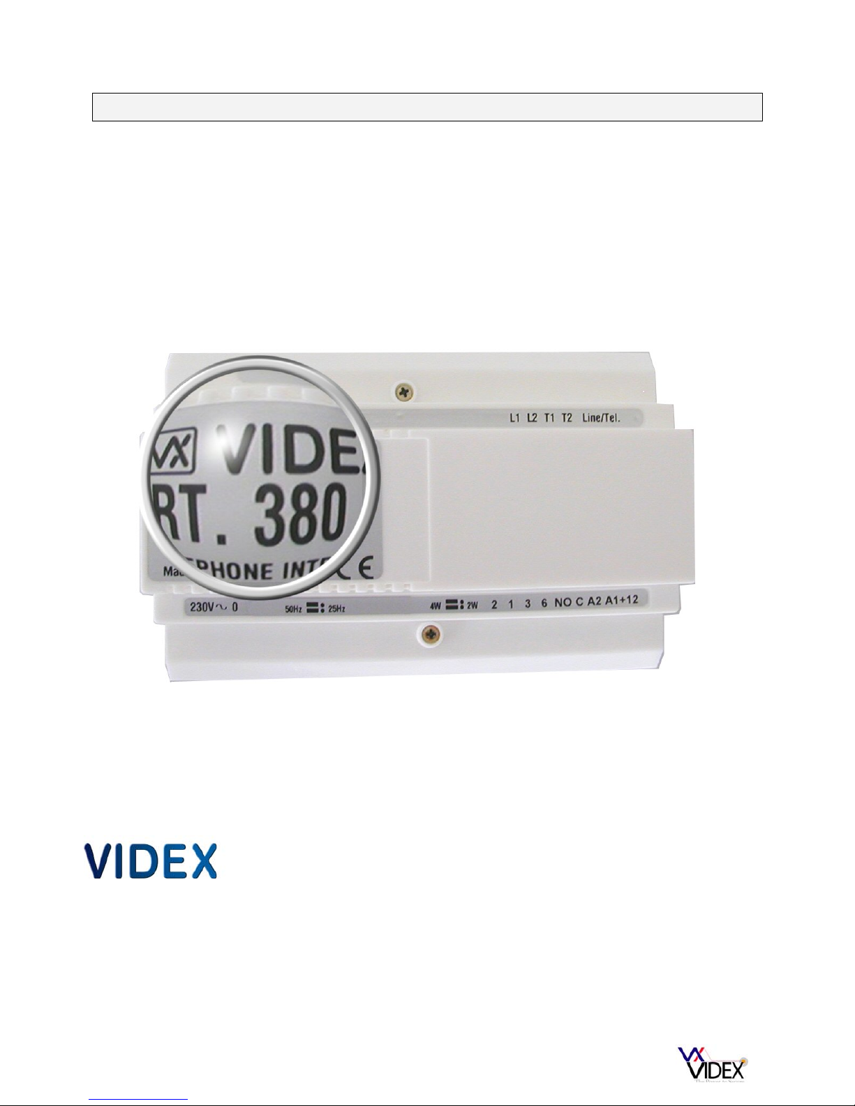
ART380N Rev03 TELEPHONE INTERFACE MANUAL
Installation and programming manual
Version 1.3
06/2013
Page 2

2 of 19
CONTENTS
DESCRIPTION PAGE
Introduction ------------------------------------------------- 3
Mounting Instructions ------------------------------------------------- 3
Safety notes ------------------------------------------------- 3
Connections to the telephone line ------------------------------------------------- 3
Dealing with other telephone equipment ------------------------------------------------- 4
Dealing with Broadband ------------------------------------------------- 4
Wiring directions ------------------------------------------------- 5
Connecting more than one handset ------------------------------------------------- 6
Lock release back EMF protection ------------------------------------------------- 6
Cable size ------------------------------------------------- 7
Jumper setting ------------------------------------------------- 7
Programming overview ------------------------------------------------- 7
Tones overview ------------------------------------------------- 8
Initial setup ------------------------------------------------- 9
Optional call adjustments ------------------------------------------------- 10
Setting the auxiliary outputs ------------------------------------------------- 10
Advanced speech setup options ------------------------------------------------- 11
Dial in facility setup ------------------------------------------------- 11
Divert call setup ------------------------------------------------- 12
Access code setup ------------------------------------------------- 13
Specialised setup ------------------------------------------------- 13
User commands ------------------------------------------------- 14
Approval ------------------------------------------------- 14
Troubleshooting ------------------------------------------------- 15
Specification ------------------------------------------------- 15
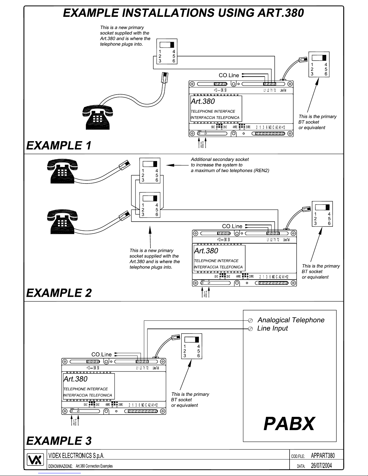
Telephone connection examples ------------------------------------------------- 16
Wiring diagram 1 (837M amplifier) ------------------------------------------------- 17
Wiring diagram 2 (837 amplifier) ------------------------------------------------- 18
Wiring diagram 3 (VK6N) ------------------------------------------------- 19
SPECIFICATION: Supply voltage 230V AC
Max number of telephone 2
Enclosure material ABS plastic
Dimensions 157.5mm(L) x 105mm(W) x 65mm(H) [Standard 9 module DIN box]
+12V out 100mA Max
Relay contacts 2A DC, 2A AC resistive 1A AC inductive - 24VDC 120V AC
Page 3

3 of 19
Introduction
The Art380 is a self contained telephone interface module for use on an analogue telephone
line. Its primary function is to enable a user to communicate with a telephone line and a door
entry point (or points) from the same telephone handset. This handset can be a standard
corded model, a cordless such as a DECT telephone or even a hands free telephone. The
Art380’s main features are listed below:-
o Communicate with both a telephone line and door entry points.
o Open a door using the telephone keypad.
o Open the speech to a door entry point without first being called.
o Activate up to two auxiliary outputs. (Outputs can be either momentary or latching).
o Reverse the door open relay for use with power to lock releases.
o Make the following call adjustments in programming mode:-
Number of rings (From 1 – 10 rings)
Door open time (From 1 – 18 seconds)
Door open key (Either 0(default), 8 or 9)
Internal/external speech volume.
o Divert the call to another pre-programmed number. or is engaged).
o Program an access code to protect the programming and the use of facilities in either
divert mode or normal mode.
o PABX mode (Allows the units to operate without the need for a telephone line).
o Dial in facility which allows the Art380 to be activated from an incoming telephone call.
Mounting instructions
The Art380 can be either mounted to a DIN rail or mounted directly to a wall. Begin by
removing the terminal side covers by unscrewing the retaining screws. Either clip the Art380
to a DIN rail or screw directly to the wall using two screws and suitable wall plugs. You should
leave the terminal side covers off until all connections have been made.
Safety notes
The system must be installed by a competent installer following the regulations in force. We
recommend:-
Use an appropriate fused spur to isolate the mains from the Art380.
Isolate the mains before removing any covers from the system (Please note: There are no
user serviceable parts within the Art380 and so the covers should only be removed by a
competent technician).
Connections to the telephone line
Each telephone line coming into your home or office must be fitted with a six pin primary
socket installed by the PTO (Public Telecommunication Operator). It is illegal to tamper in any
way with this primary socket and you can’t install it yourself. Additional connections to the
primary socket must be carried out using a BT style plug (You cannot connect directly to the
terminals inside). The ART380 telephone interface unit is supplied with a BT style plug. For
more information, see relevant paper work supplied with extension sockets.
Page 4
4 of 19
When connecting additional equipment to a telephone line it is good practise to first check the
equipment already installed by previous engineers. This includes any additional secondary
sockets, digital set top box such as Sky Digital, faxes, modems, Broadband and REDCARE
alarm monitoring etc. The following precautions should be observed when connecting to any
of the named above:-
Secondary sockets
If secondary sockets are installed, open each one and check it is a secondary socket and not
another master (A secondary socket will not contain any components whereas a master
socket will have a capacitor, resistor and suppressor fitted). Only one master socket should
be connected after the Art380. If there are more than one fitted they must be replaced with
secondary (Slave) sockets. (Also note: The Art380 is only capable of ringing two handsets
with a REN value of 1 each).
Sky Digital, Faxes, Redcare and modems
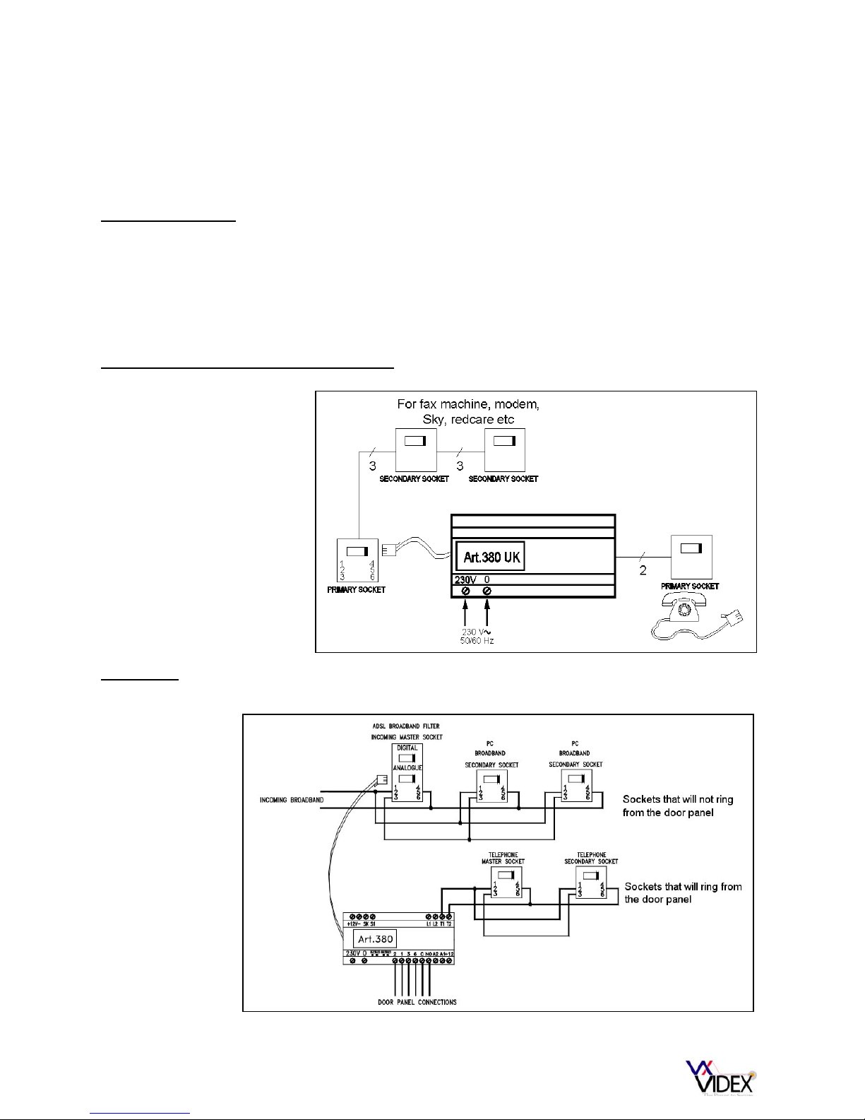
Broadband
On installations with broadband it is important to connect the Art380 into the system as shown
below:-
Sky digital, fax machines,
Redcare or any other
form of telephone line
based monitoring and
conventional modems
must be fitted before the
Art380 and not after.
Note: The
Art380 must
always connect
after an ADSL
Filter.
Page 5
5 of 19
Wiring directions
Please follow the appropriate wiring diagram from one of the pages at the rear of this manual.
For information purposes, the connections on the Art380 have the following functions:-
CONNECTION DESCRIPTION EXPECTED OUTPUT
230V Live terminal for mains input to
the device.
This should be connected to the mains via a
fused spur
0 Neutral terminal for mains input to
the device.
This should be connected to the mains via a
fused spur
2 Receive speech from the door
panel.
Approx. 8-12V DC during standby or approx.
1V DC when the speech to the door panel is
open.
1 Transmit speech to the door panel Approx. 8 – 12V DC during standby or
approx. 4V DC when the speech to the door
panel is open.
3 Ground Use this connection as a reference point for
voltage checks.
6 Call line to trigger a call from a
door panel.
0V in standby and approx. 12V AC or DC
when the call button is pressed.
C Common connection of door open
relay.
Dry contact. Continuity checks can be made
between C & NO.
NO Normally open or normally closed
connection of door open relay
depending on programmed state.
Dry contact. Continuity checks can be made
between C & NO.
A2 Auxiliary 2 output Open collector output. Becomes a 0V when
activated. Can be either latched or momentary
depending on programming. Also can be used
to automatically trigger a camera depending
on programming. (Max. 200mA)
A1 Auxiliary 1 output Open collector output. Becomes a 0V when
activated. Can be either latching or
momentary depending on programming. (Max
200mA).
+12 +12V DC output. Can be used to trigger a relay in conjunction
with A1 or A2. Maximum current output
available is 100mA.
+12 +12V DC output Can only be used to power Videx serial bus
modules designed to work with the Art380.
- 0V 0V connection. Can only be used to power
Videx serial bus modules designed to work
with the Art380.
SK Clock signal For use with Videx serial bus devices.
Normally sits at 12V DC. Will alternate
during data transfer.
SI Data signal For Videx serial bus devices. Normally sits at
12V DC. Will alternate during data transfer.
Page 6
6 of 19
L1 Telephone line input Can be used as an alternative connection to
the RJ11 socket.
L2 Telephone line input Can be used as an alternative connection to
the RJ11 socket.
T1 Telephone output
T2 Telephone output
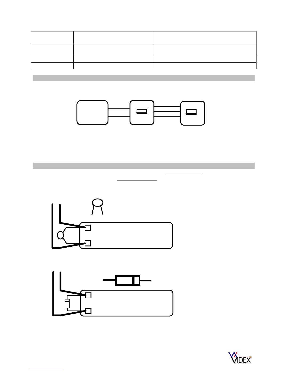
Connecting more than one handset
Up to one additional handset can be connected, using secondary telephone sockets as
shown in the diagram below.
ART380
Interface
Primary Secondary
T1
T2
2
5
2
3
5
2
3
5
If more telephones are required. They should be connected to the Art380 via a REN booster
(The REN booster is a third party product not supplied by Videx). IMPORTANT NOTE: When
using a REN boost the Art.380 must be put into PABX mode. It will then be necessary
to press ‘0’ to get an outside line.
Lock release back EMF protection
A capacitor must be fitted across the terminals on an AC lock release and a diode must be
fitted across the terminals on a DC lock release to suppress back EMF voltages. The
diagrams below show how to connect these components to the lock releases.
LOCK RELEASE
12V AC
~~
0.1uF capacitor
+
-
1N4002
+
-
12V DC
LOCK RELEASE
DIODE
Page 7

7 of 19
Cable size and type
When running cables for any intercom system, these cables must be installed separately from
the mains cables. All multi pair cables should be to CW1308 specification. (0.5mm twisted
pair telephone cable). Max resistance = 10 Ohm.
Lock release wires should be doubled up. Max resistance = 3 Ohm
The cable sizes above can be used for distances up to 50m. On distances above 50m the
cable sizes should be increased to keep the overall resistance of the cable below the
RESISTANCE’S indicated above.
The total length of standard telephone wiring between the primary and any extension socket
must not exceed 50M. The total length from the primary socket to the furthest secondary
socket must not exceed 100M.
Jumper settings
There are four jumpers on the Art380 labelled S1, S2, S3 and S4. Jumpers S1 & S2 are used
to setup the telephone ringing frequency as either 50Hz or 25Hz:-
Jumpers S3 & S4 are for setting the speech circuit type to either 2 wire or four wire. A four
wire system would be either a 837, 836, 831K, 537 or 536, 2280 amplifier in the door panel
and a 2 wire system would be either a 831M or a 835 amplifier in the door panel.
Programming overview
Most of the features of the Art380 can be adjusted using the telephone keypad connected to
the output of the Art380. This will need to be a ‘Tone dial’ telephone capable of producing
DTMF tones. After each programming function, the handset should be replaced. Confirmation
tones can be heard at the end of each segment of programming to either indicate if the
information entered has been accepted and understood or if the information has not been
Page 8

8 of 19
understood and so is required to be entered again. If during the programming, a mistake is
made, simple hang up the telephone and start again.
Tones overview
Upon lifting the handset you should hear the telephone line tone. (If the system is in PABX
mode you will still hear a line tone but this will be a higher frequency to the one normally
heard on a telephone line.
On entering ** to gain access to the functions and programming facility the line tone will
change to a higher frequency (Note: When in PABX mode the tone stays the same.
Upon pressing the first digit of the programming command, the line tone will stop.
As you type the command digits, you will hear the DTMF tones.
Upon completion of the command you will hear a double beep to confirm the command
was accepted. If you hear a number of fast beeps or an engaged tone, the command has
not been accepted and you should replace the handset and start again.
The fast beeps will also indicate an incorrect access code if this facility has been setup to
secure access to the programming menu.
The following table is a quick guide to the programming. This will be followed by a more
descriptive guide to the programming:
NOTE: THE PROGRAMMING MENU IS PROTECTED. TO ENTER PROGRAMMING
MODE, PICK UP THE HANDSET AND TYPE **371. THE FOLLOWING COMMANDS ARE
THEN AVAILABLE. THESE COMMANDS CAN BE CARRIEDOUT BACK TO BACK
WITHOUT HANGING UP. IF YOU DO HANG UP IT WILL BE NECCESSARY TO UNLOCK
THE PROGRAMMING AGAIN.
IF THE ACCESS CODE FEATURE IS ENABLED THEN YOU MUST ENTER THIS AFTER
THE **. FOR EXAMPLE ** 1234 371
Description Code Variant X Default X
Relay reversal (NO or
NC)
10 X
X = 1 or 0 (1 for a normally closed circuit for use
with power to lock releases and 0 for a normally
open circuit for power to open releases.
0
Alternate between
local call and divert
mode.
11 X
X = 1 or 0 (1 for divert mode & 0 for local call
mode)
0
Dial in facility
enable/disable
12 X
X = 0 or 1 (1 for enabling the dial in facility and 0
for disabling the dial in facility)
0
Pulse mode
13 X
X = 0 or 1 (0 to disable pulse dial facility and 1 to
enable)
0
PABX mode
14 X
X = 0 or 1 (0 for normal mode and 1 for PABX
mode)
0
** mode disable
17 X
X = 0 or 1 (0 to enable ** reading and 1 to
disable)
0
Direct DTMF reading
18 X
X = 0 or 1 (0 to disable direct reading and 1 to
enable direct reading)
1
AUX 2 direct control
19 X
X = 0 or 1 (0 to allow A2 to automatically trigger
upon a call and 1 for direct control by user)
1
Access code
enable/disable for
20 X
X = 0 or 1 (0 to enable the code for local use and 1
to disable the code during local use)
1
Page 9

9 of 19
local use.
Number of rings
21 X
X = 0 to 9 (0 = 10 rings, 1 – 9 = number of rings) 6
Door open time
22 X
X = 0 to 9 (0 = 1 second, 1 – 9 multiplied by 2. i.e.
X = 3, time = 6 seconds. X = 4, time = 8 seconds).
3
Door open key
23 X X = 0, 8 or 9
0
Divert call/dial in time
24 X
X = 0 to 9 (X multiplied by 30 seconds = time. i.e.
X = 2, time = 60 seconds. X = 4, time = 120
seconds).
2
Dial in number of
rings
25 X
X = 0 to 9 (0 = 10 rings. 1 to 9 = number of rings
before automatically answering)
5
Tone detection
26 X
X = 0 (Disable tone detection) 1 (Enable tone
detection)
1
Speech volume
towards the entrance
panel
27 X
X = 1 to 9 ( 1 = lowest volume and 9 = maximum
volume)
5
A1 auxiliary output
control
28 X
X = 0 or 1 (0 for latching trigger and 1 for
momentary trigger)
1
A2 auxiliary output
control
29 X
X = 0 or 1 (0 for latching trigger and 1 for
momentary trigger)
1
At home control
30 X
X = 0 or 1 (0 to activate at home control and 1 to
disable)
1
Access code
31 XXXX
X = four digit access code (Must begin with
either 1, 2, 3 or 4) (1111 to disable)
No code
Divert phone numbers
32 1 n #
n = Telephone number(Example: program the
number as 0123 456789 would be ** 32 1
0123456789 # and to program the second as
NOTE: Always confirm the number using the #
key.
N/A
Revert to default
settings
33 1111
Resets all setting to default N/A
Reassurance tone at
the door panel
34 X
X = 0 or 1 (1 to activate reassurance tone and 0 to
deactivate)
0
Divert to number after
n seconds
35 X
X = 0 – 9 (0 to disable the divert and 1 – 9
multiplied by 4 for time. i.e. When X = 3 time will
be 12 seconds before automatic divert)
0
Divert mode audio
automatically on/off
36 X
X = 0 or 1 (0 to enable the speech automatically
and 1 to manually open the speech by pressing 2
after answering the call.
0
Page 10

10 of 19
Programming & User functions explained
Initial setup:
Begin by resetting the Art380 to the factory defaults: ** 371 33 1111
Note: If you are unable to reset using this process because you have enabled a code but are
not sure what it is then follow the following manual reset procedure:
1. Switch off the power to the Art380
2. Short terminals - & SK
3. Switch on the power to the Art380
4. Remove the short between terminals - & SK
5. The Art380 has now been reset to factory default settings.
This method will also switch the Art380 into PABX mode and so to revert the unit back to
normal mode, pickup the handset and type ** 371 14 0.
Optional call adjustments
The following adjustments can be made to tailor the system to a clients requirements:
Remember: After picking up the handset first type ** 371 to unlock the programming
commands.
Adjust the number of rings:
The Art380 can be
programmed to ring the
telephone(s) for as little as 1
ring or for a maximum of 10
rings using one of the following
codes:-
Code Rings Code Rings
21 1 1 21 6 6
21 2 2 21 7 7
21 3 3 21 8 8
21 4 4 21 9 9
21 5 5 21 0 10
Adjust the door open time:
The Art380 can be
programmed to release the
door for as little as 1 second
up to a maximum of 18
seconds:-
Code Seconds Code Seconds
22 0 1 22 5 10
22 1 2 22 6 12
22 2 4 22 7 14
22 3 6 22 8 16
22 4 8 22 9 18
Relay reversal: The contacts
on the relay for the door
release are normally open
(NO). This can be changed to
a normally closed contact for
use with power to lock
releases:-
Code Status Code Status
10 1 NC 10 0 NO
Changing the door open
key: The door open key is 0
when factory defaulted but can
be changed to either 8 or 9:-
Code Key Code Key
23 0 0 23 8 8
23 9 9
Page 11

11 of 19
Setting up the auxiliary outputs
There are two auxiliary outputs available on the Art380 labelled A1 and A2. These outputs are
a switched negative (Open collector) and can be used for a number of facilities including
activating dry contact relays. The outputs can be set to latch on activation or switch
momentarily.
Using auxiliary outputs:
To activate auxiliary 1 (A1) during a call simply press 5. If the auxiliary output is set to latch
then it will be necessary to press 5 again to unlatch the output.
To activate auxiliary 1 (A1) without a call being in progress simply pick up the handset and
press ** [Code] 5. If the output is set to latch, follow the same procedure to unlatch.
To activate auxiliary 2 (A2) during a call simply press 6. If the auxiliary output is set to latch
then it will be necessary to press 6 again to unlatch the output.
To activate auxiliary 2 (A2) without a call being in progress simply pick up the handset and
press ** [Code] 6. If the output is set to latch, follow the same procedure to unlatch.
Additionally, Auxiliary output A2 can be programmed to automatically activate when a call is
placed. Please note: If A2 is set to activate automatically it can not also be set to latch as
indicated above.
Dial in facility setup
The dial in facility can be used to allow a caller from a telephone line to dial into the Art380
and access the functions available. This could be to open the door or activate an auxiliary
output.
Code Output Code Output
28 0 A1 Latching 28 1 A1 Momentary
29 0 A2 Latching 29 1 A2 Momentary
Code Output Code Output
19 0 Automatic 19 1 Manual
Activating / deactivating the
dial in facility:
Code Facility
12 (0) Disabled (Default)
12 (1) Enabled
Activate after a number of
rings: The Art380 can count the
number of rings before it activates
and tales hold of the call. This can
be set from 1 – 10 rings. (Note:
Each BT ring is a double ring and
so counts as two rings.)
Code Rings Code Rings
25 (1) 1 25 (6) 6
25 (2) 2 25 (7) 7
25 (3) 3 25 (8) 8
25 (4) 4 25 (9) 9
25 (5) 5 25 (0) 10
Dial in time/Divert time: The dial
in time can be set from 30
seconds to 300 seconds. This is
the maximum time a call can last
for before clearing down and
releasing the line.
Code Seconds Code Seconds
24 (1) 30 24 (6) 180
24 (2) 60 24 (7) 210
24 (3) 90 24 (8) 240
24 (4) 120 24 (9) 270
24 (5) 150 24 (0) 300
Latching or momentary
output:
Page 12

12 of 19
Divert call setup
The divert facility allow a call to be diverted to another telephone number. When in divert
mode it is recommended you use a four digit access code to restrict the functions of the
Art380 to authorised callers. Also see box above for divert time which is the time allowed
before a call will clear.
Access code setup
The access code is used to restrict access to the programming menu and commands. It can
be disabled, setup for both local calls and diverted calls or setup for just diverted calls.
To program the divert
telephone number: The
telephone number can be a
maximum of 40 digits in length.
Code
32 1 number # First telephone number
To switch between divert mode
and normal mode: When in
divert mode and a call is placed,
the Art380 will ring the telephone
number stored without ringing the
telephone connected to the output
of the Art380.
Code Divert mode
11 1 Activated
11 0 Deactivated
Edit or delete code:
Code
31 XXXX Change the code to XXXX
31 1111 Delete the code
To setup the system to divert
the call automatically after a
preset number of seconds:
When this mode is enabled, the
telephone in the house will ring
for the number of seconds
programmed and if after this
period the call still has not been
answered, it will divert to the preprogrammed telephone.
Code Seconds Code Seconds
35 (1) 4 35 (6) 24
35 (2) 8 35 (7) 28
35 (3) 12 35 (8) 32
35 (4) 16 35 (9) 36
35 (5) 20 35 (0)
Disabled
Code Automatic speech enable
36 1 Must press 2 to open speech
36 0 Speech opens automatically
Speech automatically open
when answering a divert call:
When set to 1 it will be necessary
to press 2 after answering a call
that has been diverted to your
phone. This feature disables the
door panel amplifier until 2 is
pressed so that no dialling sounds
are heard and the caller is not
aware of the call being diverted.
Example 1 -A call diverted to a mobile phone when **36 1 is set:-
1. The mobile phone will ring and the caller display will show that it is from the
telephone number attached to the Art380.
2. Answer the call. No sound will be heard.
3. Press 2. The speech will open to the door panel.
Example 2 – A call diverted to a mobile phone when **36 0 is set:-
1. The mobile phone will ring and this will be heard from the door panel as well.
2. Answer the call. Speech will open automatically.
Page 13

13 of 19
Specialised setup
The following options can be adjusted for specialised situations. For standard installations
these setting will not normally need to be adjusted.
Code Tone detection
26 0 Disabled
26 1 Enabled (Default)
Pulse mode: The pulse mode
facility can be used with old pulse
style telephones which can not
generate DTMF tones.
Code Pulse mode
13 0 Disabled (Default)
13 1 Activated
PABX mode: PABX mode can be
used on systems which do not
have a telephone line or have a
telephone line but needs to be
isolated from it. When this is
activated it will be necessary to
press 0 to select the telephone
line before dialling a number.
Code PABX Mode
14 0 Disabled (Default)
14 1 Activated
Note: It is also possible to put the Art380 into PABX
mode by following these steps:
1. Switch the mains off to the Art380
2. Short terminals - & SK.
3. Turn on the mains to the Art380
4. Remove the short from terminals - & SK (After
a short click)
Note: This procedure also defaults the Art380.
Disable ** Mode: An alternative
to using the ** to enter
programming is RECALL RECALL
or FLASH FLASH.
Code **
17 0 Enabled (Default)
17 1 Disabled
Direct DTMF reading: Allows the
tones to be read during a call by
the Art380 without first pressing **
Code DTMF Reading
18 0 Disabled
18 1 Enabled (Default)
At home control: This feature
allows the ‘divert call’ to be
automatically switched off when
active by simply picking up one of
the handsets on the output of the
Art380 and replacing it.
Code At home control
30 0 Enabled
30 1 Disabled (Default)
Enable/Disable access code for
local calls:
Code Enabled or disabled
20 0 Enabled
20 1 Disabled (Default)
Tone detection: Detection of line
tones such as busy, no answer,
call end etc. Sometimes
necessary to disable tone
detection to avoid false detection.
Page 14

14 of 19
Speech adjustments
Speech volume control is adjustable for both directions using the POTS on the entrance panel speaker unit.
Additionally, speech volume towards the door panel can be adjusted from the telephone using the following
procedure:-
1. Lift the handset and type ** 371 to enter programming mode
2. Type 27 X (Where X = 1 to 9) 9 being maximum volume and 1 being lowest volume.
3. Replace the handset and make a test call to check volume
Volume towards the door can also be adjusted during the call be pressing 27X(X=1-9)
User commands
The following commands can be used to activate functions of the Art380. Note: If the code facility is active, this
will be required before the command will work.
Command Function
Either 0, 8 or 9
depending on
programming
Open the door during a call.
1
During dial in mode, pressing 1 will enable the divert facility.
2
Press 2 during dial in mode to open the speech to the door panel. Also press 2
after answering a call in divert mode to open the speech to the door panel
(When this mode is active i.e. **361)
5
Activate auxiliary 1
6
Activate auxiliary 2 (Only when aux 2 is set to direct control.
0
Connect to telephone line (PABX mode only)
**7
Open speech to door without first being called and switch between calls.
7
During divert mode it will end the call and switch off the door panel.
(Recommended way to end a diverted call)
#
Clear to start again if a mistake is made when typing code in the divert mode.
User command examples: (Note: The examples are for default settings)
To open the speech to the door panel without first being called **7
To divert to a door call while talking on the telephone **7
(Note: To go back to the telephone call simply hang up and then pick up again)
To divert to a telephone call while talking to the door **7
(Note: To go back to the door call, simply hang up and then pick up again)
To open the door without first being called **0
To open the door during a call 0
To put the system in divert mode **111
To take the system back out of divert mode **110
To activate auxiliary 1 without first being called **5
To activate auxiliary 2 without first being called **6
To activate auxiliary 1 during a call 5
To activate auxiliary 2 during a call 6
To activate the speech when dialling in 2
To activate the speech in divert mode (When setting **361 is set) 2
APPROVAL
The equipment has been approved in accordance with Council Decision 98/482/EC for pan-European single terminal connection to the public
switch telephone network (PSTN). However, due to differences between the individual PSTNs provided in different countries, the approval
does not, of itself, give an unconditional assurance of successful operation on every PSTN network termination point.
In the event of problems, you should contact your equipment supplier in the first instant.
Your Art.380 telephone interface is fully approved to be connected to the following circuits : Public Switched Telephone Network (PSTN) - Non DDI
Private Branch Exchange (PBX)
If the unit is to be used on any other network that is not listed above, you must first contact the vendor.
The Art380 telephone interface complies fully with the requirements of TBR21 in all modes of operation.
Page 15

15 of 19
Troubleshooting guide
In the event of problems occurring during the installation of the Art380 telephone interface please check this troubleshooting guide before
calling the Videx technical help on 0191 224 3174.
Telephone does not ring but if it is picked up during a call there is speech to the door :-
Option 1 : The REN value has been exceeded. Do the test again with only one telephone c onnected. If it works then the
REN value has been exceeded and the number of telephone on the system must be reduced.
Option 2 : A master socket has not been fitted to the output of the ART380. The telephone will not ring if this is a secondary
socket or a faulty master socket. (The master socket has a large capacitor inside.)
Option 3 : The correct voltage is not coming from the Art380. (An AC voltage of appro x. 30 volts should be present across
T1 & T2 during the ringing cycle).
The speech lines do not open when ** 7 is pressed :-
Option 1 : The ** facility has been disabled on the Art380. To enable this, pick up the ha ndset and press RECALL RECA LL
17 0. Hang up the telephone. The Art380 is now programmed to accept **.
Option 2 : The telephone you are using does not support DTMF dialling.
The door does not open when ‘0’, ‘8’ or ‘9’ is pressed :-
Option 1 : The telephone you are using does not support DTMF dialing.
Option 2 : The lock is not wired correctly to the Art380. The Art380 has a dr y c ontact r el ay o utput acro ss C & NO. T hese two
terminals short together when the door open is activated.
The door opens when it should close and closes when it should open:-
Option 1 : The relay has been programmed to be either normally closed when it should be normall y open or normally open
when it should be normally closed. Reprogram the Art380 relay reverse correctly.
The Art380 does not activate at all when called :-
Option 1 : Check the mains supply is connected to the Art380 and is correct.
Option 2 : Check the mains fuse inside the Art380.
Option 3 : Use a meter to check it is getting a signal across terminals 3 and 6 when a call is placed. The voltage across
these two terminals should be 12V AC or DC. (Without this voltage the Art380 will not trigger).
There is no dial tone when the handset is lifted :-
Option 1 : Check there is a line tone before the Art380 by moving the telephone to the line input.
Option 2 : Check the line cord is connected to the incoming master socket and that the cord is not faulty.
Option 3 : Check the new master socket fitted across terminals T1 & T2 of the Art380N has the wires connected to terminals
2 and 5.
Option 4 : Check the telephone being used is working correctly.
No speech from the door panel to the telephone :-
Option 1 : Check terminal 2 from the door panel to the Art380. When there are n o calls on the system a voltage of 8V DC
should be present across 2 and negative.
Option 2 : If possible, test the door panel speech with a Videx telephone.
No speech from the telephone to the door panel :-
Option 1 : Check terminal 1 from the door panel to the Art380. When there are n o calls on the system a voltage of 8V DC
should be present across 1 and negative.
Option 2 : If possible, test the door panel speech with a Videx telephone.
The speech is to loud and feed back occurs.
Option 1 : Try adjusting the volume at the door panel. (POTS on rear of amp module)
Option 2 : Try adjusting the internal/external volume using function codes 26 & 27 of the programming menu.
Option 3 : Check the unit is not in handset free mode.
If help is required for installing or operating this unit, please contact our technical department on:
+39 734 631669 (all countries) or 0191-224-3174 (UK Only)
Page 16
Page 17

Page 18

Page 19

 Loading...