

Page 1
Page 2

Page 3

Index
INDEX ........................................................................................................................................................................... 3
ART.4333 ...................................................................................................................................................................... 4
SPEAKER UNIT WITH BUILT-IN CAMERA ..........................................................................................................................................................................................4
ART.3181 ...................................................................................................................................................................... 6
DIGITAL INTERCOM FOR VX2300 2 WIRE SYSTEM..........................................................................................................................................................................6
ART.3381 ...................................................................................................................................................................... 8
DIGITAL VIDEOPHONE FOR VX2300 2 WIRE SYSTEM......................................................................................................................................................................8
ART.5488 .................................................................................................................................................................... 11
HANDS FREE VIDEOMONITOR SPECIFIC FOR VX2300 ...................................................................................................................................................................11
ART.317 ...................................................................................................................................................................... 15
FOUR WAY DISTRIBUTION BOX .....................................................................................................................................................................................................15
ART.2301/4 ................................................................................................................................................................. 16
ENTRANCES EXCHANGER FOR VX2300 DIGITAL SYSTEMS ............................................................................................................................................................16
ART.2305 .................................................................................................................................................................... 17
EXTENSION RELAY FOR VX2300 DIGITAL SYSTEMS .....................................................................................................................................................................17
ART.2321-2321/P ........................................................................................................................................................ 18
POWER SUPPLIES FOR VX2300...................................................................................................................................................................................................18
GENERAL DIRECTIONS FOR INSTALLATION ............................................................................................................ 19
Page 4
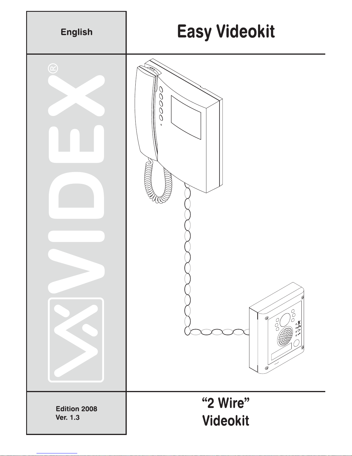
Two Wire Videokit ESVK Series
PrtCode:ESVK_ENG_1.3 – Pag.4/24
23/10/2008 Rev.1.3
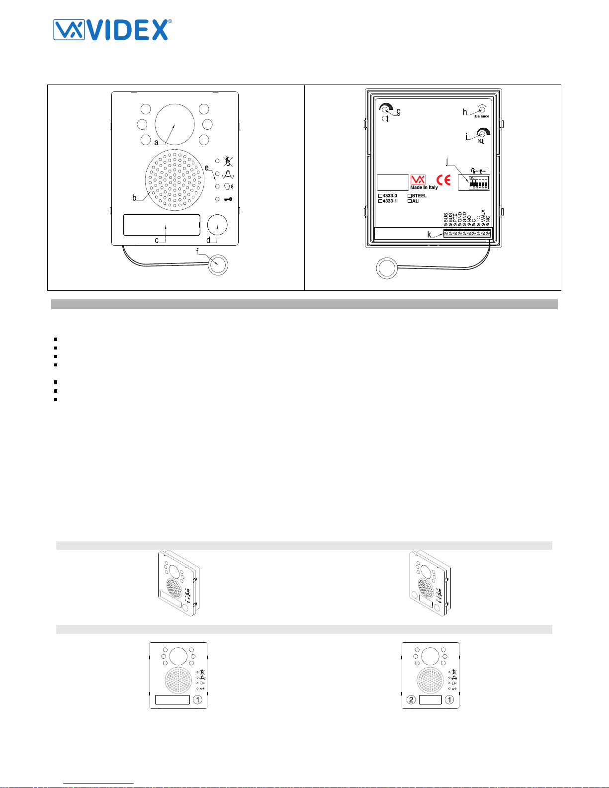
Art.4333
Speaker unit with built-in camera
Fig.1 Fig.2
DESCRIPTION
Speaker unit module with built-in B&W camera with autoiris lens comprised of IR illumination LEDs. According to the speaker unit version it includes one
or two call push buttons. The module is available also in colour camera version where the illumination LEDs are white light.
The unit circuitry incorporates :
The transmitting amplifier with condenser microphone and volume control;
The receiving amplifier with volume control;
The audio balance circuit with the “BALANCE” control;
The enslavement relay to enable the electric lock (3 contacts: common, normally open and normally closed). It can work also as capacitor discharge
to supply directly the electric lock;
The call buttons from 1 to a maximum of 2 depending on the module version;
The illumination LEDs for the card name holder;
The camera comprised of illumination LEDs.
Module Details:
a. Camera with illumination LEDs;
b. Loudspeaker;
c. Card name holder;
d. Call push button (1 or 2 according to the model);
e. Operation LEDs
f. Microphone;
g. Microphone volume control;
h. Balance Control;
i. Loudspeaker volume control;
j. Dip-switch to carry out the following programming:
- Door station ID (switches from 1 to 3);
- Door opening time (switch 4);
- Conversation time (switch 5);
k. System connection terminals;
AVAILABLE MODULE VERSIONS
Art.4333-1, 4333-1/color
Art.4333-1D, 4333-1D/color
BUTTONS LAYOUT
Art.4333-1, 4333-1/color Art.4333-1D, 4333-1D/color
Page 5
Two Wire Videokit ESVK Series
PrtCode:ESVK_ENG_1.3 – Pag.5/24
23/10/2008 Rev.1.3
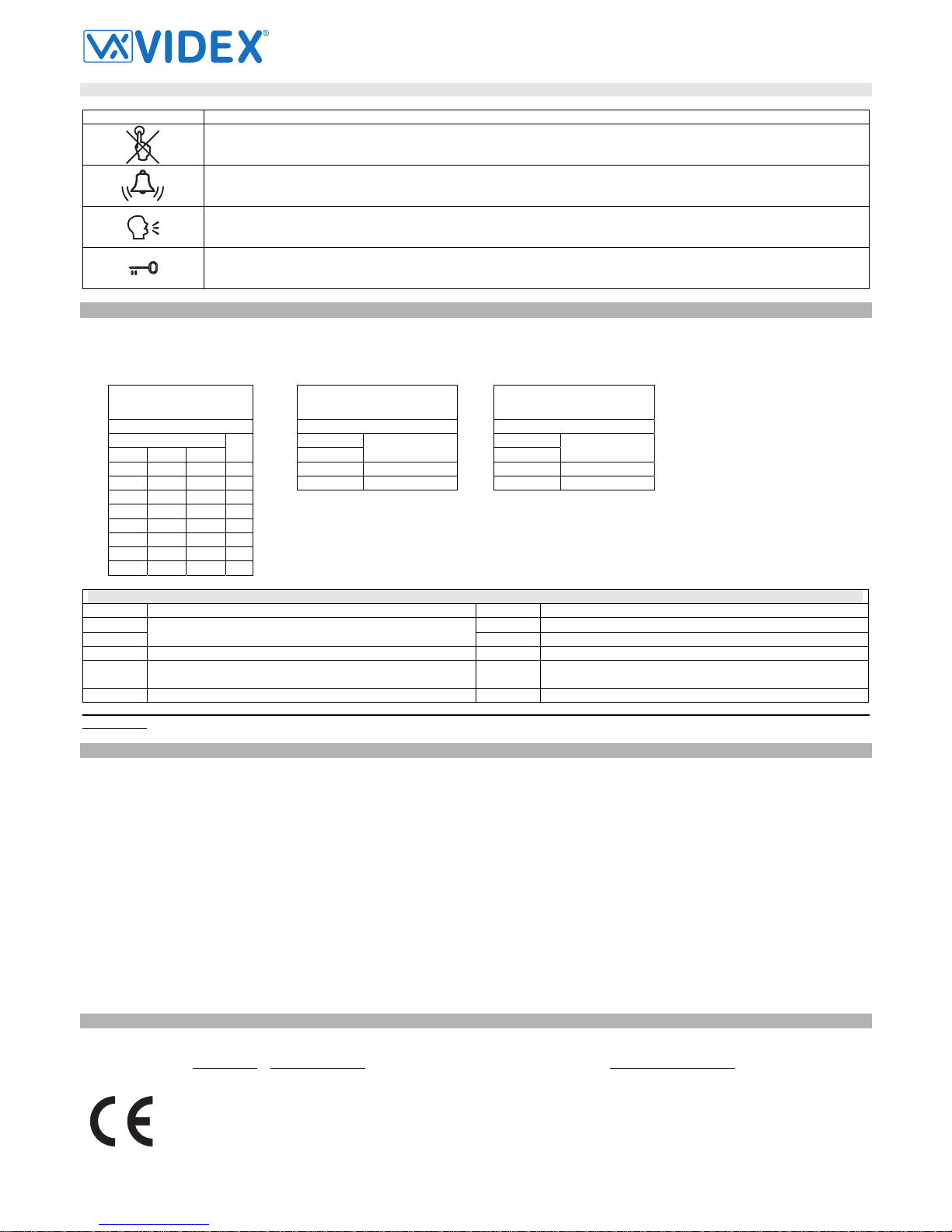
FRONT LEDS SIGNALLING DESCRIPTION
Sign Description
When illuminated, indicates that it is not possible to make a call because a call or a conversation is in progress (from the outdoor station from which you are calling or from another outdoor station on systems with multiple entrances). The LED will be
off when the system is in stand-by
If illuminated, indicates that the call from the outdoor station is in progress. The LED will switch OFF when the call is answered or after the programmed number of rings.
If illuminated, indicates that it is possible to speak because the call has been answered. The LED will switch OFF at the end
of a conversation (or at the end of the conversation time).
If illuminated, indicates that the door lock has been operated. It will switch OFF at the end of the programmed “door opening”
time.
PROGRAMMING
The programming consists of the following settings:
- Unit ID (1..8);
- Door Opening Time (3 or 6 seconds);
- Conversation Time (1 or 2 minutes);
The settings are carried out trough the 6 way dip-switch (reference j on figure 2) accessible from the rear side of the module. The switch 6 is not used.
Unit ID
Switches
1 2 3
ID
OFF OFF OFF 1
ON OFF OFF 2
OFF ON OFF 3
ON ON OFF 4
OFF OFF ON 5
ON OFF ON 6
OFF ON ON 7
ON ON ON 8
Door Opening Time
Switches
4
Seconds
OFF 3
ON 6
Conversation Time
Switches
5
Minutes
OFF 1
ON 2
SIGNALS ON SYSTEM CONNECTION TERMINALS
Terminal Description Terminal Description
BUS NO Door open relay normally open contact
BUS
Bus connection terminals
C Door open relay normally closed contact
PTE “Push to exit” active low input +C Electric lock capacitor discharge output
GND Ground
VAUX
35Vdc power supply input (if used, the module is powered
locally and not from the BUS)
GND Ground NC Door open relay normally closed contact
To use the electric lock with capacitor discharge, make a short between “C” and “+C” then connect the electric lock between terminals “NO”
and “GND”.
UNIT SPECIFICATION
Housing/Mounting
One 4000 Series Module / 4000 Series Modular System
Push Buttons
Yes, from 0 to 2 call buttons according to the model
Programming
Yes, carried out by the 6 way dip-switch located on the rear of the module
Controls
Microphone and Loudspeaker volume trimmers plus balance trimmer
Front plate Finishes
Mirror stainless steel (standard) and Anodized aluminium (add /a after the product code)
Power Supply
Supplied by the BUS line
Working Temperature
-10 +50ºC
CUSTOMER SUPPORT INFORMATION
All Countries Customers UK Customers
VIDEX Electronics S.p.A.
www.videx.it
– technical@videx.it
Tel.+39 0734 631669
Fax +39 0734 632475
VIDEX Security LTD
www.videx-security.com
Tech Line 0191 224 3174
Fax 0191 224 1559
The product is CE marked demonstrating its conformity and is for distribution within all
member states of the EU with no restrictions.
This product follows the provisions of the European Directives
89/336/EEC & 92/31/EEC (EMC),
73/23/EEC (LVD) and 93/68/EEC (CE marking).
Il prodotto è marchiato CE a dimostrazione della sua conformità e può essere distribuito liberamente all’interno dei paesi membri dell’unione eu ropea EU.
Questo prodotto è conforme alle direttive Europee
89/336/EEC & 92/31/EEC (EMC),
73/23/EEC (LVD) e 93/68/EEC (Marcatura CE).
Page 6

Two Wire Videokit ESVK Series
PrtCode:ESVK_ENG_1.3 – Pag.6/24
23/10/2008 Rev.1.3
Art.3181
Digital intercom for VX2300 2 Wire System
Fig.1 Fig.2
DESCRIPTION
Intelligent intercom with “door open/intercommunicating call” push button (key), bus relay (Art.2305) activation button (dot), “privacy ON-OFF” switch,
“door open” and “privacy on” LEDs and call tone volume control (3 levels). To avoid a BUS arrest in case a user forgot the handset picked up, each operation must be executed within 10 seconds after the handset is picked up otherwise to perform an operation it is necessary to hang up the handset and
pick up it again.
PUSH BUTTONS, LEDS AND CONTROLS (FIG.1)
a Door open push button – Intercommunicating call. For an intercommunicating call, pick up the handset and press as many times as the
extension or address value to call (see SW3 Intercommunication Settings).
b Activate bus relay board Art.2305 push button. To activate a bus relay pick up the handset and press as many times as the address
value of the relay.
c Door Open LED. Switched ON if the door is open. Its correct operation depend from correct connection
d Privacy ON LED. Switched ON when the privacy service is active
e Privacy ON-OFF switch. The privacy duration time can be programmed. If the intercom is programmed for a specific privacy duration,
after the service is enabled switching to “ON” position (red LED ON), the service will be automatically
f Call tone volume control (3 levels)
DIP-SWITCHES AND JUMPERS (FIG.2)
SW1 Switches from 1 to 7 are used for unit address (from 1 to 127 binary coded). Last switch (8) is not used
SW2 Switches 2,3 and 4 are used to set privacy duration time. The switch 1 is not used.
SW3 Switches 1,2 and 3 are used to for intercommunication settings. The switch 4 is not used.
S1 Impedance terminator. The jumper must be normally closed. When more videophones/intercoms are connected in parallel (from a pe-
ripheral to another and so on until the last) the jumper must be open for all the intercoms except for the last following the connection or-
der.
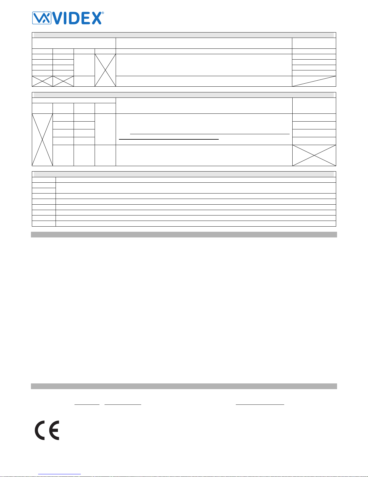
PROGRAMMING
SW1 – INTERCOM ADDRESS
Switches Status Binary Code – Decimal Value
7 6 5 4 3 2 1 64 32 16 8 4 2 1
Decimal
Code
OFF OFF OFF OFF OFF OFF ON 0 0 0 0 0 0 1 1
OFF OFF OFF OFF OFF ON OFF 0 0 0 0 0 1 0 2
OFF OFF OFF OFF OFF ON ON 0 0 0 0 0 1 1 3
OFF OFF OFF OFF ON OFF OFF 0 0 0 0 1 0 0 4
OFF ON OFF OFF ON OFF ON 0 1 0 0 1 0 1 37
ON ON OFF OFF OFF ON ON 1 1 0 0 0 1 1 99
The table above shows how to set the address of the videophone. Considering that ON = 1 and OFF = 0, multiply each digit for the relevant decimal
weight then sum values obtained to get the address: E.g. as highlighted in the table OFF,ON,OFF,OFF,ON, OFF,ON in binary is equal to 0100101 then
multiplying each digit for the relevant decimal weight you obtain the address that is 37.
Note
The maximum number of units allowed is 64 but the address of each unit can be a value between 1 and 99
Page 7
Two Wire Videokit ESVK Series
PrtCode:ESVK_ENG_1.3 – Pag.7/24
23/10/2008 Rev.1.3
SW2 – PRIVACY DURATION TIME
Switches Status
Privacy Mode
(switch 2)
Privacy Duration
(switches 3,4)
4 3 2 1
OFF OFF 15 minutes
OFF ON 1 hour
ON OFF 4 hours
ON ON
OFF
The privacy duration time is set by the switches 3 and 4. After enabled the privacy
service is disable when the time set expire or the relevant button is pressed again.
8 hours
ON
No privacy time expiration: the privacy service is enabled or disabled only by the
relevant button.
SW3 – INTERCOMMUNICATION SETTINGS
Switches Status
4 3 2 1
Intercommunication Mode
(switch 1)
Videophone
Extension
(switches 2,3)
OFF OFF 1
OFF ON 2
ON OFF 3
ON ON
OFF
Intercommunication allowed between videophones (same unit address) inside the
same flat. To call an extension pick up the handset then press the “door open” button
as many times as the extension value is (Eg. extension 2 two times, 3 three times
etc). If there are more videophones/intercoms connected in parallel, one at
least must be set with switches 2 and 3 to OFF
4
OFF OFF ON
Intercommunication allowed between videophones (different unit address) inside different flats. To call an extension pick up the handset then press the “door open” button as many times as the address value is (Eg. extension 10 ten times, 12 twelve
times etc)
SIGNALS ON CONNECTION TERMINALS
Signal Description
BUS
BUS
Bus contacts
LED-
Door open LED ground signal input
LED+
Door open LED power supply input
GND
Ground signal
GND
Local Bell contact
AL
Alarm input (not implemented)
LB
Local Bell contact (put a push button between this terminal and the relevant GND terminal)
SPECIFICATION
Housing/Mounting
3000 Series Intercoms / direct wall mounting
Push Buttons
Yes, two
Programming
Yes, carried out by the dip-switches inside the intercom
Controls
Call tone volume and privacy ON-OFF switch
Power Supply
Supplied by the BUS line
Working Temperature
-10 +50ºC
CUSTOMER SUPPORT INFORMATION
All Countries Customers UK Customers
VIDEX Electronics S.p.A.
www.videx.it
– technical@videx.it
Tel.+39 0734 631669
Fax +39 0734 632475
VIDEX Security LTD
www.videx-security.com
Tech Line 0191 224 3174
Fax 0191 224 1559
The product is CE marked demonstrating its conformity and is for distribution within all
member states of the EU with no restrictions.
This product follows the provisions of the European Directives
89/336/EEC & 92/31/EEC (EMC),
73/23/EEC (LVD) and 93/68/EEC (CE marking).
Il prodotto è marchiato CE a dimostrazione della sua conformità e può essere distribuito
liberamente all’interno dei paesi membri dell’unione eu ropea EU.
Questo prodotto è conforme alle direttive Europee
89/336/EEC & 92/31/EEC (EMC),
73/23/EEC (LVD) e 93/68/EEC (Marcat ura CE).
Page 8
Two Wire Videokit ESVK Series
PrtCode:ESVK_ENG_1.3 – Pag.8/24
23/10/2008 Rev.1.3
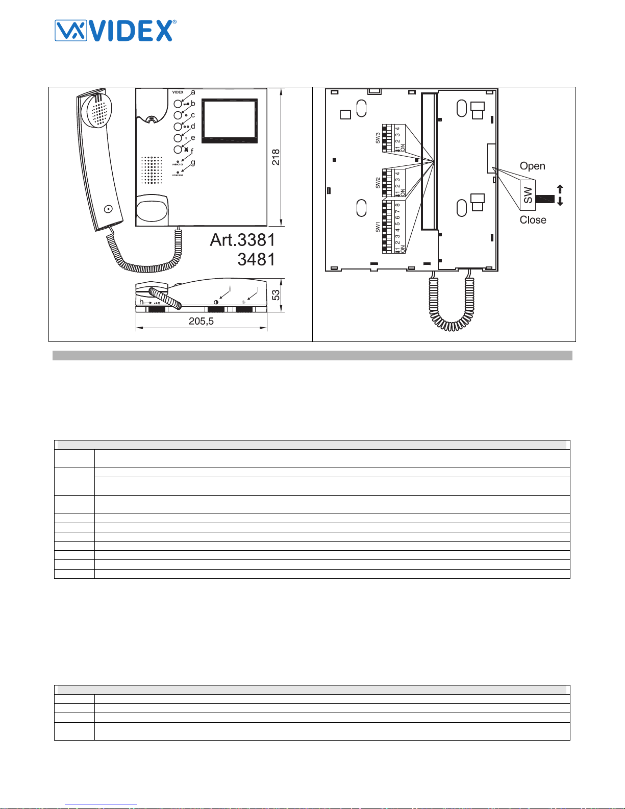
Art.3381
Digital videophone for VX2300 2 Wire System
Fig.1 Fig.2
DESCRIPTION
Intelligent videophone with 4” flat screen B&W monitor with “door open” and “camera recall” push buttons, bus relay enable button, service button, “privacy ON-OFF” button plus “privacy on” and “door open” LEDs. Controls: 3 levels of call tone volume (both main and local) plus contrast and brightness.
The videophone is available also in color version Art.3481 that uses a 3,5” active matrix LCD monitor. To avoid a BUS arrest in case a user forgot the
handset picked up, each operation must be executed within 10 seconds after the handset is picked up otherwise to perform an operation it is necessary
to hang up the handset and pick up it again.
PUSH BUTTONS, LEDS AND CONTROLS (FIG.1)
a Door open push button – Intercommunicating call. For an intercommunicating call, pick up the handset and press as many times as the
extension or address value to call (see SW3 Intercommunication Settings).
Camera recall push button. Pick up the handset and press as many times as the DEVICE N. of the door station to switch on. b
If the door station uses the Art.4303N plus the Art.4330N, pressing this button during a conversation switches the video signal coming
from the camera module to the video signal coming from the camera module input for external camera.
c Activate bus relay board Art.2305 push button. To activate a bus relay pick up the handset and press as many times as the address
value of the relay.
d Service push button.
e Privacy ON-OFF push button. The privacy duration time can be programmed.
f Privacy ON LED. Switched ON when the privacy service is active.
g Door Open LED. Switched ON if the door is open. Its correct operation depend from correct connection (terminals 1 and 18)
h Call tone volume control (3 levels)
i Contrast control (left decrease, right increase)
l Brightness control (left decrease, right increase)
DIP-SWITCHES AND SWITCHES (FIG.2)
SW1 Switches from 1 to 7 are used for unit address (from 1 to 127 binary coded). Last switch (8) is not used
SW2 Switches 2,3 and 4 are used to set privacy duration time. The switch 1 is not used.
SW3 Switches 1,2 and 3 are used to for intercommunication settings. The switch 4 is used to set the slave mode.
SW Impedance terminator. The standard position is “close”. When more videophones are connected in parallel (from a videophone to an-
other and so on until the last) it must be set to “open” for all the videophones except for the last following the connection order.
Page 9

Two Wire Videokit ESVK Series
PrtCode:ESVK_ENG_1.3 – Pag.9/24
23/10/2008 Rev.1.3
PROGRAMMING
After each programming operation carried out through dip-switches or jumpers it is necessary to temporary disconnect the videophone from the BUS or
from the power supply if locally powered.
NUMBER OF RINGS
The number of rings can be set to 3 (factory preset) or 6.
To change the number of rings proceed as follow:
- Unplug the flat cable from the pcb connection board;
- Put in short the terminals 13 and 14;
- Plug-in the flat cable checking the privacy on LED and remove the short between terminals 13 and 14;
- The number of LED flashes will be 1 for 3 rings setup and 3 for 6 rings setup.
Each time this operation is carried out the number of rings is switched between the values 3 and 6.
SW1 – VIDEOPHONE ADDRESS
Switches Status Binary Code – Decimal Weight
7 6 5 4 3 2 1 64 32 16 8 4 2 1
Address
OFF OFF OFF OFF OFF OFF ON 0 0 0 0 0 0 1 1
OFF OFF OFF OFF OFF ON OFF 0 0 0 0 0 1 0 2
OFF OFF OFF OFF OFF ON ON 0 0 0 0 0 1 1 3
OFF OFF OFF OFF ON OFF OFF 0 0 0 0 1 0 0 4
OFF ON OFF OFF ON OFF ON 0 1 0 0 1 0 1 37
ON ON OFF OFF OFF ON ON 1 1 0 0 0 1 1 99
The table above shows how to set the address of the videophone. Considering that ON = 1 and OFF = 0, multiply each digit for the relevant decimal
weight then sum values obtained to get the address: E.g. as highlighted in the table OFF,ON,OFF,OFF,ON, OFF,ON in binary is equal to 0100101 then
multiplying each digit for the relevant decimal weight you obtain the address that is 37.
Note
The maximum number of units allowed is 64 but the address of each unit can be a value between 1 and 99.
SW2 – PRIVACY DURATION TIME
Switches Status
Privacy Mode
(switch 2)
Privacy Duration
(switches 3,4)
4 3 2 1
OFF OFF 15 minutes
OFF ON 1 hour
ON OFF 4 hours
ON ON
OFF
The privacy duration time is set by the switches 3 and 4. After enabled the privacy
service is disable when the time set expire or the relevant button is pressed again.
8 hours
ON
No privacy time expiration: the privacy service is enabled or disabled only by the
relevant button.
SW3 – INTERCOMMUNICATION SETTINGS
Switches Status
4 3 2 1
Intercommunication Mode
(switch 1)
Videophone
Extension
(switches 2,3)
OFF OFF 1 (Master)
OFF ON 2 (Slave)
ON OFF 3 (Slave)
ON ON
OFF
Intercommunication allowed between videophones (same unit address) inside the
same flat. To call an extension pick up the handset then press the “door open” button
as many times as the extension value is (Eg. extension 2 two times, 3 three times
etc). If there are more videophones/intercoms connected in parallel, one at
least must be set with switches 2 and 3 to OFF
4 (Slave)
OFF OFF ON
Intercommunication allowed between videophones (different unit address) inside different flats. To call an extension pick up the handset then press the “door open” button as many times as the address value is (Eg. extension 10 ten times, 12 twelve
times etc)
Slave Mode (switch 4) for Extensions 2, 3 and 4
OFF Factory preset, during a call the videophone will ring only (while the master will show also the video) to show the video only if used to an-
swer.
ON During a call, the videophone will ring showing also the video: in this case the videophone must be powered locally using an Art.2321 and
connecting BUS+ to “Vin” (9) and BUS- to “–“ (10).
In case of more units (videophones or intercoms) in a parallel connection, apart from the status of switch 1 (intercommunication mode), the
extension programming must be always performed and the master unit (extension 1) must be always present.
Page 10

Two Wire Videokit ESVK Series
PrtCode:ESVK_ENG_1.3 – Pag.10/24
23/10/2008 Rev.1.3
VIDEOPHONE CONNECTION BOARD ART.3980
As 3000 series videophones also this version uses the Art.3980 connection board.
Fig.3
SIGNALS ON TERMINALS OF ART.3980 CONNECTION BOARD
Terminal Signal Description
1 -LD
Door open LED ground signal input
2 AL
Alarm input (not implemented)
3 S
4 S
Contacts for “S” service push button. Linked together when the button is pressed
5 GND
Ground signal
6
7
8
9 Vin
10 -
Auxiliary power supply input (for local power supply)
11 BUS
12 BUS
Bus contacts
13 14 LB
Local bell contacts
15
16
17
18 +LD
Door open LED power supply (12Vdc)
SPECIFICATION
Housing/Mounting
3000 Series Videophones / mounting plate plus connection board
Push buttons
Yes, 5
Programming
Yes, carried out by the dip-switches located on the rear of the videophone
Controls
Call tone volume, contrast and brightness
Power Supply
Supplied by the BUS line
Working Temperature
-10 +50 ºC
CUSTOMER SUPPORT INFORMATION
All Countries Customers UK Customers
VIDEX Electronics S.p.A.
www.videx.it
– technical@videx.it
Tel.+39 0734 631669
Fax +39 0734 632475
VIDEX Security LTD
www.videx-security.com
Tech Line 0191 224 3174
Fax 0191 224 1559
The product is CE marked demonstrating its conformity and is for distribution within all
member states of the EU with no restrictions.
This product follows the provisions of the European Directives
89/336/EEC & 92/31/EEC (EMC),
73/23/EEC (LVD) and 93/68/EEC (CE marking).
Il prodotto è marchiato CE a dimostrazione della sua conformità e può essere distribuito
liberamente all’interno dei paesi membri dell’unione eu ropea EU.
Questo prodotto è conforme alle direttive Europee
89/336/EEC & 92/31/EEC (EMC),
73/23/EEC (LVD) e 93/68/EEC (Marcat ura CE).
Page 11

Two Wire Videokit ESVK Series
PrtCode:ESVK_ENG_1.3 – Pag.11/24
23/10/2008 Rev.1.3
Art.5488
Hands Free Videomonitor specific for VX2300
164
130,00
53
1
2
3
4
Fig.1 Fig.2
DESCRIPTION
An intelligent Hands-free (surface or flush mounting) video monitor employing a colour 3.5” active matrix LCD display, with push buttons for “door
open/intercommunicating call”, “answer/camera recall”, “privacy on/off”, “BUS relay activation” and 2 service buttons plus 4 LED’s associated with 4
main buttons. In addition to the above the unit has controls for loudspeaker volume, call tone volume, brightness and hue with programmable number of
rings, privacy duration and intercommunication mode.
PUSH BUTTONS, LEDS AND CONTROLS (FIG.1)
Service push button - When pressed, shorts terminal “S1” to terminal “GND” (ground).
Bus Relay Button - Activate bus relay board Art.2305 push button. To activate a bus relay pick up the handset and press as many times
as the address value of the relay.
Answer button - On an incoming call, operation of this button allows the user to answer and converse with the visitor. The LED 2 will illu-
minate.
Camera recall button - Press as many times as the DEVICE N. of the door station to switch on.
Switch off button - With the system switched on (monitor on), momentary operation of the button will switch the video monitor off. The
videomonitor will also automatically switch off after a time delay if the button is not pressed. The LED 2 will switch off.
Simplex button - Pressing and holding the button for more than 3 seconds will switch the videomonitor into SIMPLEX speech mode.
Press and hold the button to speak to the caller (The LED 2 will flash rapidly), release the button to listen (The LED 2 will flash slowly). If
the button is not pressed for 10 seconds the videomonitor will switch off. The videomonitor will revert to duplex speech when another call
is made.
When pressed, shorts terminal “S2” to Terminal “GND” (ground).
Privacy on-off button - Press and keep pressed for more than 3 seconds to enable/disable the service. The relative LED will illuminate
when the privacy service is enabled. The operation must be performed with the videomonitor switched on (during a conversation or cam-
era recall).
Camera exchange button - With a conversation in progress, press rapidly to switch from door station camera to external camera (re-
quires Art.4330N and external camera) and viceversa.
Intercommunicating call button - For an intercommunicating call, when the videomonitor is in stand-by, press as many times as the ex-
tension or address value to call.
Door open button - During a call, operation of this button will activate the “door open” relay (NO1, NC1, COM1). The LED 4 will illuminate
if terminal 6 has been connected to a door contact.
1
Not present
2
LED relative to the operation of the answer/switch off/camera recall/simplex button
3
LED relative to the operation of privacy button
4
LED relative to the operation of door open button (powered from the connection terminal “6” of Art.5980)
Loudspeaker volume control
Call tone volume control
Brightness control
Colour intensity control
Page 12

Two Wire Videokit ESVK Series
PrtCode:ESVK_ENG_1.3 – Pag.12/24
23/10/2008 Rev.1.3
PROGRAMMING
The videomonitor setup consists of the following settings:
- Number of Rings;
- Unit address (1..127, switches 1 to 7 of SW1);
- Bus Termination (open or close, switch 8 of SW1);
- Intercommunication mode (between apartments or extension switch 1 of SW3);
- Extension address (1..4, switches 2,3 of SW3);
- Slave mode (switch 4 of SW3);
- Privacy duration (switches 1,2 and 3 of SW2)
The number of rings programming is carried out through the videomonitor push buttons , for the other settings operates the three dip-switch banks
(SW1, SW2 and SW3) on the rear side of the video monitor.
Except the number of rings programming, other programmings, to be stored, it is necessary to remove temporary the power supply.
NUMBER OF RINGS
First of all make a camera recall to switch on the unit then proceed with the programming operation.
To alter the number of rings, the videomonitor must be in programme mode. This is achieved by operating the two following buttons at the same time
(left button of the volume control and the right button of the colour intensity control) see Fig.1A 8 small buttons towards the bottom of the face plate (far
left button and far right button together). When the programming mode is entered LED 1 (Fig.1A) starts flashing. This will automatically reset after 20
seconds of idle time. When in the programming mode press and hold the “
” button, LED 1 will stop flashing and LED 2 (Fig.1A) will start to flash
showing the number of rings (each flash = 1 ring i.e. 6 flashes = 6 rings) once the value of rings has been reached release the “
” button. Wait approx
10 seconds that the LED 1 stops flashing to signal that the new value is stored and the exit from the programming .
VIDEOMONITOR ADDRESS – SW1.1..7
The table above shows how to set the address of the videophone. Considering that ON = 1 and OFF = 0, multiply each digit for the relevant decimal
weight then sum values obtained to get the address: E.g. as highlighted in the table OFF,ON,OFF,OFF,ON, OFF,ON in binary is equal to 0100101 then
multiplying each digit for the relevant decimal weight you obtain the address that is 37.
Switches Status Binary Code – Decimal Weight
7 6 5 4 3 2 1 64 32 16 8 4 2 1
Ad-
dress
OFF OFF OFF OFF OFF OFF ON 0 0 0 0 0 0 1 1
OFF OFF OFF OFF OFF ON OFF 0 0 0 0 0 1 0 2
OFF OFF OFF OFF OFF ON ON 0 0 0 0 0 1 1 3
OFF OFF OFF OFF ON OFF OFF 0 0 0 0 1 0 0 4
OFF ON OFF OFF ON OFF ON 0 1 0 0 1 0 1 37
ON ON ON ON ON ON ON 1 1 1 1 1 1 1 127
Note
The maximum number of units allowed is 100 but the address of each unit can be a value between 1 and 127.
BUS TERMINATION - SW1.8
The factory preset for this switch is ON: termination enabled. In case of more units (intercoms, videophones or
video monitors) in a parallel connection (bus wires are connected to the terminals of the first unit then from this
to the second and so on up to 4 units max) the switch 8 must be set to ON only for the last unit of the chain
while on all other units must be set to OFF (bus termination disabled).
INTERCOMMUNICATION MODE – SW3.1
This switch establish the intercommunication mode: in position OFF (default) is enabled the intercommunication
between units in the same apartment (same addresses but different extension); in position ON is enabled the
intercommunication between units in different apartments (different addresses).
EXTENSION NO – SW3.2..3
If the intercommunication between apartments is enabled (switch 1 of SW3 = ON) leave these two switches in default position (both to OFF). Otherwise,
if the intercommunication between the same apartment is enabled (switch 1 of SW3 = OFF), set the extension address es starting always from 1. During
the external call, all video monitors in the same flat will ring but the video will be shown only from the videmononitor with extension address 1.
2 3 Extension No.
OFF OFF 1 (default, master)
ON OFF 2 (slave)
OFF ON 3 (slave)
ON ON 4 (slave)
SLAVE MODE - SW3.4
This set up concern the answering mode of the video monitor when there are more units (max 4) in a parallel
connection (same address, different extensions). OFF (default) = during a call, only the video monitor with extension 1 (master) will show the video coming from the door station. ON = the video monitor will be switched on
independently of the extension address: in this case the video monitor must be supplied locally using a power
supply Art.2321 and connecting respectively BUS+ to terminal 14 and BUS- to terminal 11 of the pcb connec-
tion board provided with the Art.5980.
Page 13

Two Wire Videokit ESVK Series
PrtCode:ESVK_ENG_1.3 – Pag.13/24
23/10/2008 Rev.1.3
PRIVACY UNLIMITED – SW2.1
If this switch is set to OFF (default), the privacy duration is defined from the switches 2 and 3 programming.If
this switch is set to ON, the privacy duration is unlimited and the service can be enabled or disabled only by
the relative button.
PRIVACY DURATION – SW2.2..3
This set up requires that the switch 1 is set to OFF.
2 3 Duration
OFF OFF 15 minutes
ON OFF 1 hour
OFF ON 4 hours
ON ON 8 hours
VIDEOMONITOR CONNECTION BOARD ART.5980
Fig.3
SIGNAL ON CONNECTION TERMINALS
Terminal Signal Description
1 GND
Ground
2 BUS1
Bus input
3
4 BUS2
Bus input
5 S1 Terminal controlled by the S1 button, close to GND until the button is pressed
6 LED
Auxiliary LED power supply input (12Vdc)
7 S2 Terminal controlled by the S2 button, close to GND until the button is pressed
8 GND
Ground
9 GND
Ground
10 LB
Ingresso per chiamata di piano (attivo basso)
11 GND
Ground
12
13
14 +VAUX
Auxiliary power supply input (to be used when the switch 4 of SW2 is set to ON)
15
16
17
18 AL
Alarm input (not implemented yet)
19
20
Page 14

Two Wire Videokit ESVK Series
PrtCode:ESVK_ENG_1.3 – Pag.14/24
23/10/2008 Rev.1.3
VIDEOMONITOR WALL MOUNTING INSTRUCTIONS
Fig.1 Fig.2
Fig.3 Fig.4
- Cables must be fed through the opening “e” (Fig. 2A) of the mounting plate “c”, which should be fitted approximately 135cm from finished floor level as
shown in Fig 1;
- Place the mounting plate “c” against the wall feeding the wire group “d” through opening “e” of the mounting plate and mark the fixing holes “a” (Fig.
2A)
- Drill the fixing holes “a”, insert the wall plugs “b” then with the cables threaded through opening “e” fix the mounting plate “c” to the wall with the 4
screws provided “f” (Fig. 2A).
- Hook the pcb connection board “g” to the mounting plate “c”as shown in Fig2B and connect the wires (using the screwdriver provided) to the terminals
as shown in the diagram provided;
- Once the wires are connected, hook the videophone “h” to the Mounting plate “c” as shown in Fig. 3.
• Connect the Plug “I” on the ribbon cable from the videophone to the plug “l” on the PCB connection board “g”;
• Place the videophone “h” against the 4 hooks “m” on the mounting plate “c” (in line with the 4 openings “n” on the rear side of the videophone Fig. 4)
and push down as suggested by the pointers in Fig. 3, the videophone will lock into place;
- To remove the videophone, hold it firmly and push the unit in an upward direction until the videophone “h” unlocks from the mounting plate “c”.
SPECIFICATION
Housing/Mounting
5000 Series Videophones / mounting plate plus connection board
Push buttons
Yes, 6
Programming
Yes, carried out by the dip-switches located on the rear of the videophone
Controls
Call tone volume, contrast and hue
Power Supply
Supplied by the BUS line
Working Temperature
-10 +50 ºC
CUSTOMER SUPPORT INFORMATION
All Countries Customers UK Customers
VIDEX Electronics S.p.A.
www.videx.it
– technical@videx.it
Tel.+39 0734 631669
Fax +39 0734 632475
VIDEX Security LTD
www.videx-security.com
Tech Line 0191 224 3174
Fax 0191 224 1559
The product is CE marked demonstrating its conformity and is for distribution within all
member states of the EU with no restrictions.
This product follows the provisions of the European Directives
89/336/EEC & 92/31/EEC (EMC),
73/23/EEC (LVD) and 93/68/EEC (CE marking).
Il prodotto è marchiato CE a dimostrazione della sua conformità e può essere distribuito liberamente all’interno dei paesi membri dell’unione eu ropea EU.
Questo prodotto è conforme alle direttive Europee
89/336/EEC & 92/31/EEC (EMC),
73/23/EEC (LVD) e 93/68/EEC (Marcatura CE).
Page 15

Two Wire Videokit ESVK Series
PrtCode:ESVK_ENG_1.3 – Pag.15/24
23/10/2008 Rev.1.3
Art.317
Four way distribution box
Fig.1 Fig.2
DESCRIPTION
The unit distribute the bus signal to 4 outputs linked to videophones or intercoms. The distributor have 3 levels (low, medium and high) of signal amplification, the amplification operate only on the 4 outputs and not on the through output.
CONNECTION TERMINALS AND JUMPERS
Terminal/Jumper Description
BUS IN
Bus input terminals
BUS OUT
Bus output terminals (through output)
BUS OUT 1
Videophone/Intercom bus output 1
BUS OUT 2
Videophone/Intercom bus output 2
BUS OUT 3
Videophone/Intercom bus output 3
BUS OUT 4
Videophone/Intercom bus output 4
B1
Close/Open bus output to BUS OUT 1. Move to close when the BUS OUT 1 is not used.
B2
Close/Open bus output to BUS OUT 2. Move to close when the BUS OUT 2 is not used.
B3
Close/Open bus output to BUS OUT 3. Move to close when the BUS OUT 3 is not used.
B4
Close/Open bus output to BUS OUT 4. Move to close when the BUS OUT 4 is not used.
BL
Close/Open bus through output. If the distributor is the last move to close otherwise leave open.
AMPLIFICATION
Set the requested level of amplification choosing between low, medium and high
SPECIFICATION
Housing/Mounting
Plastic box 70x110x30mm / direct wall mounting
Push Buttons
N/A
Programming
N/A
Controls
Outputs amplification (3 levels)
Power Supply
Supplied by the BUS line
Working Temperature
-10 +50ºC
CUSTOMER SUPPORT INFORMATION
All Countries Customers UK Customers
VIDEX Electronics S.p.A.
www.videx.it
– technical@videx.it
Tel.+39 0734 631669
Fax +39 0734 632475
VIDEX Security LTD
www.videx-security.com
Tech Line 0191 224 3174
Fax 0191 224 1559
The product is CE marked demonstrating its conformity and is for distribution within all
member states of the EU with no restrictions.
This product follows the provisions of the European Directives
89/336/EEC & 92/31/EEC (EMC),
73/23/EEC (LVD) and 93/68/EEC (CE marking).
Il prodotto è marchiato CE a dimostrazione della sua conformità e può essere distribuito liberamente all’interno dei paesi membri dell’unione eu ropea EU.
Questo prodotto è conforme alle direttive Europee
89/336/EEC & 92/31/EEC (EMC),
73/23/EEC (LVD) e 93/68/EEC (Marcatura CE).
Page 16

Two Wire Videokit ESVK Series
PrtCode:ESVK_ENG_1.3 – Pag.16/24
23/10/2008 Rev.1.3
Art.2301/4
Entrances exchanger for VX2300 digital systems
Fig.1 Fig.2
DESCRIPTION
This unit allows to exchange the bus signal between 4 entrances on system with multiple entrances. It has 4 inputs for 4 door stations, two power supply
inputs (to use both when required) and one bus output
CONNECTION TERMINALS AND JUMPERS
Terminal/Jumper Description
BUSBUS+
BUS Output (polarized only when directly connected to the power supply)
IN1
Door station input 1
IN2
Door station input 2
IN3
Door station input 3
IN4
Door station input 4
PS1
Power Supply input 1
PS2
Power Suppy input 2
SPECIFICATION
Housing/Mounting
9 Module A Type DIN box / DIN Bar or directly to the wall
Push Buttons
N/A
Programming
N/A
Controls
N/A
Power Supply
From specific power supply or from the bus
Working Temperature
-10 +50ºC
CUSTOMER SUPPORT INFORMATION
All Countries Customers UK Customers
VIDEX Electronics S.p.A.
www.videx.it
– technical@videx.it
Tel.+39 0734 631669
Fax +39 0734 632475
VIDEX Security LTD
www.videx-security.com
Tech Line 0191 224 3174
Fax 0191 224 1559
The product is CE marked demonstrating its conformity and is for distribution within all
member states of the EU with no restrictions.
This product follows the provisions of the European Directives
89/336/EEC & 92/31/EEC (EMC),
73/23/EEC (LVD) and 93/68/EEC (CE marking).
Il prodotto è marchiato CE a dimostrazione della sua conformità e può essere distribuito liberamente all’interno dei paesi membri dell’unione eu ropea EU.
Questo prodotto è conforme alle direttive Europee
89/336/EEC & 92/31/EEC (EMC),
73/23/EEC (LVD) e 93/68/EEC (Marcatura CE).
Page 17

Two Wire Videokit ESVK Series
PrtCode:ESVK_ENG_1.3 – Pag.17/24
23/10/2008 Rev.1.3
Art.2305
Extension Relay for VX2300 digital systems
Fig.1 Fig.2
DESCRIPTION
This unit can be connected directly to the bus and have two operating modes: extension relay and extension ring. As extension relay, the built-in relays
are controlled by the relevant button of the intercom or videophone while as extension ring the relay one will operate on each ring and the relay two will
operate for the duration of call time.
CONNECTION TERMINALS & DIP-SWITCHES
Terminal/Jumper Description
BUS
Input/Output bus connection terminals
BUS
Input/Output bus connection terminals
C2
Relay 2 common contact
NO2
Relay 2 normally open contact
NC2
Relay 2 normally closed contact
C1
Relay 1 common contact
NO1
Relay 1 normally open contact
NC1
Relay 1 normally closed contact
DIP-SW
8 way dip-switch to set the relay operating mode
PROGRAMMING
The operating mode is selected by the switch 8.
EXTENSION RELAY – SWITCH 8 = OFF
When the unit is set as extension relay, switches from 1 to 6 are used to set the relays addresses and activation time.
Switches Switches Switches
1 2
Relay 1,2
Addresses
3 4
Relay 1
Time
5 6
Relay 2
Time
OFF OFF 1,2 OFF OFF 2 seconds OFF OFF 2 seconds
ON OFF 3,4 ON OFF 4 seconds ON OFF 4 seconds
OFF ON 5,6 OFF ON 16 seconds OFF ON 16 seconds
ON ON 7,8 ON ON 32 seconds ON ON 32 seconds
The switch 7 is not used.
For example if the switch 1 is set to ON and the switch 2 is set to OFF (addresses 3,4), pressing 3 times the “dot” button of the intercom (or “two dot” of
the videophone) will operate the relay one while pressing 4 times will operate the relay two.
EXTENSION RING – SWITCH 8 = ON
When the unit is set in this mode, the switches from 1 to 7 (8 is not used) are used to set the address of the unit: the address of the unit is set by the
same way of the videophone or intercom (refer to intercom/videophone SW1 settings).
When is called the address set for the unit, the relay 1 will operate 4 times (one each ring) while the relay 2 will operate for the duration of call time
(about 60 seconds). The unit stop to operates if the call is cancelled or the user answer from the videophone/intercom with the same address.
As extension ring the unit operates only on call from door station.
SPECIFICATION
Housing/Mounting
5 Module A Type DIN box / DIN bar or directly to the wall
Push Buttons
N/A
Programming
Yes, carried out by the 8 way dip-switch
Controls
N/A
Power Supply
from the bus
Working Temperature
-10 +50ºC
Dry contacts relay
Max 24Vac/dc 5A
CUSTOMER SUPPORT INFORMATION
All Countries Customers UK Customers
VIDEX Electronics S.p.A.
www.videx.it
– technical@videx.it
Tel.+39 0734 631669
Fax +39 0734 632475
VIDEX Security LTD
www.videx-security.com
Tech Line 0191 224 3174
Fax 0191 224 1559
The product is CE marked demonstrating its conformity and is for distribution within all
member states of the EU with no restrictions.
This product follows the provisions of the European Directives
89/336/EEC & 92/31/EEC (EMC),
73/23/EEC (LVD) and 93/68/EEC (CE marking).
Il prodotto è marchiato CE a dimostrazione della sua conformità e può essere distribuito liberamente all’interno dei paesi membri dell’unione eu ropea EU.
Questo prodotto è conforme alle direttive Europee
89/336/EEC & 92/31/EEC (EMC),
73/23/EEC (LVD) e 93/68/EEC (Marcatura CE).
Page 18

Two Wire Videokit ESVK Series
PrtCode:ESVK_ENG_1.3 – Pag.18/24
23/10/2008 Rev.1.3
Art.2321-2321/P
Power supplies for VX2300
65
157,5
105
Art.2321
0V
230V
+
_
BUS
Fig.1 Fig.2
DESCRIPTION
These two units are specific power supplies for VX2300 digital system. The 2321 can be used for systems with 1 entrance up to 20 users while the
2321/P is for systems with more than 1 entrance and up to 64 users.
CONNECTION TERMINALS AND JUMPERS
Terminal/Jumper Description
0
~230V
Mains input
BUS +
BUS -
BUS terminals
BUS +
BUS -
BUS terminals (only Art.2321/P)
V1
V2
V3
Jumper to adjust the output voltage (only Art.2321/P). V1=Low, V2=Medium, V3=Maximum. Set to maximum (V3) when the
unit is used together the entrances switch otherwise leave to a low or medium level
CONNECTION TO MAINS AND POWER SUPPLY MOUNTING INSTRACTIONS
The system must be installed according to national rules in force, in particular we recommend to:
- Connect the system to the mains through an all-pole circuit breaker which shall have contact separation of at least 3mm in each pole and shall disconnect all poles simultaneously;
- The all-pole circuit breaker shall be placed for easy access and the switch shall remain readily operable.
POWER SUPPLY INSTALLATION
- Remove the terminal side covers by unscrewing the retaining screws;
- Fix the power supply to a DIN bar or directly to the wall using two expansion type screws;
- Switch off the mains using the circuit breaker mentioned above and then make the connections as shown on the installation diagrams;
- Check the connections and secure the wires into the terminals;
- Replace the terminal covers and fix them using the relevant screws;
- When all connections are made, restore the mains.
SPECIFICATION
Housing/Mounting
9 Module A Type DIN box (Art.2321) – 15 Module A Type DIN box (Art.2321/P) / DIN Bar or directly to the wall
Push Buttons
N/A
Programming
N/A
Controls
Voltage amplification (3 levels)
Power Supply
230Vac
Working Temperature
-10 +50ºC
CUSTOMER SUPPORT INFORMATION
All Countries Customers UK Customers
VIDEX Electronics S.p.A.
www.videx.it
– technical@videx.it
Tel.+39 0734 631669
Fax +39 0734 632475
VIDEX Security LTD
www.videx-security.com
Tech Line 0191 224 3174
Fax 0191 224 1559
The product is CE marked demonstrating its conformity and is for distribution within all
member states of the EU with no restrictions.
This product follows the provisions of the European Directives
89/336/EEC & 92/31/EEC (EMC),
73/23/EEC (LVD) and 93/68/EEC (CE marking).
Il prodotto è marchiato CE a dimostrazione della sua conformità e può essere distribuito liberamente all’interno dei paesi membri dell’unione eu ropea EU.
Questo prodotto è conforme alle direttive Europee
89/336/EEC & 92/31/EEC (EMC),
73/23/EEC (LVD) e 93/68/EEC (Marcatura CE).
Page 19

Two Wire Videokit ESVK Series
PrtCode:ESVK_ENG_1.3 – Pag.19/24
23/10/2008 Rev.1.3
General Directions for Installation
WIRES KINDS AND SECTIONS
The ESVK videokit can use several kind of cables that according to their specification can allow to cover distances up 400 meters. We do not recommend the use of shielded cables because of the high eddy capacity introduced.
The following table specify values of resistance, capacity and maximum distance allowed for several kinds of cables (capacity and resistance values are
referred to 100 metres of cable).
Cable Type Section (mm
2
) Resistance (Ohm) Capacity (nF) *Maximum Distance (meters)
VIDEX TW2 0,75 3,2 8 200m
CAT5 UTP 0,22 8 4,9 70m
Std Telephone Cable 0,28 6,5 5,5 100m
**Two wire 0,8 / 1 2 6,5 70m
* Between the power supply and the farthest door station or between the power supply and the farthest videophone.
** In case of housing project where it is necessary to reutilize the existing cables that could be cabled together with mains or other power cables, chec
k
in advance the practicability of the system: if the system cables are cabled together mains or other power cables, the system is directly exposed to
electromagnetic interference that may cause noises on audio/video and lost of functionality over digital communications.
In case of use of cables not in conformity with above specification it is possible a deterioration of digital and video signals.
We suggest to use twisted
cables with maximum resistance of 10 Ohm/100m for each wire (between the farthest door station and the farthest videophone) and maximum capacity
of 40nF (this value must be computed considering all the cables used in the system; the capacity/metres value is normally specified on the cable package or directly on the cable).
Page 20

PrtCode:ESVK_ENG_1.3 – Pag.20/24
23/10/2008 Rev.1.3
ESVK-1 ONE WAY TWO WIRE VIDEO DOOR ENTRY KIT
Page 21

PrtCode:ESVK_ENG_1.3 – Pag.21/24
23/10/2008 Rev.1.3
CESVK-1/ECLIPSE ONE WAY TWO WIRE VIDEO DOOR ENTRY KIT
Page 22

PrtCode:ESVK_ENG_1.3 – Pag.22/24
23/10/2008 Rev.1.3
ESVK-2 TWO WAY TWO WIRE VIDEO DOOR ENTRY KIT
Page 23

PrtCode:ESVK_ENG_1.3 – Pag.23/24
23/10/2008 Rev.1.3
CESVK-2/ECLIPSE TWO WAY TWO WIRE VIDEO DOOR ENTRY KIT
Page 24

Factory - Office
VIDEX ELECTRONICS S.p.A.
Via del lavoro,1
63020 MONTEGIBERTO (AP) - ITALY
Phone: (+39) 0734 - 631669
Fax: (+39) 0734 - 632475
www.videx.it
e-mail: info@videx.it
Main UK office:
VIDEX SECURITY LTD
1 Osprey
Trinity Park Trinity Way
London E4 8TD
Phone: (+44) 0870 3001240
Fax: (+44) 0208 - 5235825
www.videx-security.com
e-mail: info@videx-security.com
Northern UK office:
VIDEX SECURITY LTD
Unit 4-7
Chillingham Industrial Estate
Chapman Street
NEWCASTLE UPON TYNE
NE6 2XX
Phone: (+44) 0870 3001240
Tech Line: (+44) 0191 224 3174
Fax: (+44) 0191 224 1559
Greece office:
VIDEX HELLAS Electronics
48 Filolaou Str.
11633 Athens
Phone: +30 210 - 7521028/7521998
Fax: +30 210 - 7560712
www.videx.gr
e-mail: videx@videx.gr
Danish office:
VIDEX DANMARK
Hammershusgade 15
DK - 2100 Copenhagen
Phone: +45 39 29 80 00
Fax: +45 39 27 77 75
www.videx.dk
 Loading...