

Page 1
VX2200 GSM MODULE
GSM Interface Module for the VX2200 Digital System
66251225-EN
V1.0 - 08/01/18
We recommend
This equipment is installed by a
Competent Electrician, Security or
Communications Engineer.
Technical Manual
ENG
ART. 2270
Page 2
66251225-EN - V1.0 - 08/01/18
THE POWER TO SECURE
- 2 -
VX2200 GSM Interface Module - Technical Manual
GSM Interface Module for the VX2200 Digital System
EU RoHS DECLARATION OF CONFORMITY
Telit Communications certies that the UL865-EUR (Dual Band 2G EGSM900/DCS1800 and Dual Band 3G FDD I/FDD VIII Wireless
Module) is in compliance with the essential requirements and other relevant provisions of European Directive 1999/5/EC (R&TTE).
The conformity with the essential requirements of the Directive 1999/5/EC has been demonstrated against the following harmonized
standards:
Article of Directive 1999/5/EC Harmonized Standard Reference
Health & Safety (R&TTE art. 3.1a)
EN 60950-1:2006 + A11:2009 + A1:2010 + A12:2011 + AC2011
EN 62311:2008
EMC (R&TTE art. 3.1b)
EN 301 489-1 V1.9.2
EN 301 489-7 V1.3.1
EN 301 489-24 V1.5.1
RF Spectrum use (R&TTE art. 3.2)
EN 301 511 V9.02
EN 301 908-1 V5.2.1
EN 301 908-2 V5.2.1
WARNING!
To comply with FCC RF exposure requirements, a separation distance of 20cm (7.87”) or more
must be maintained between the antenna of this product and all persons.
Separate FCC approval for this product is not required as it will be classed as a xed installation.
THIS PRODUCT IS NOT DESIGNED TO BE USED AS AN EMERGENCY CALL POINT.
MANUFACTURER
All Countries:
VIDEX ELECTRONICS S.P.A.
www.videx.it - technical@videx.it
Tel: +39 0734-631699 - Fax: +39 0734-632475
The product is CE marked demonstrating its conformity and is for distribution
within all member states of the EU with no restrictions. This product follows
the provisions of the European Directives 2014/30/EU (EMC); 2014/35/EU
(LVD); 2011/65/EU (RoHS): CE marking 93/68/EEC.
UK Customers:
VIDEX SECURITY LTD.
www.videxuk.com - tech@videxuk.com
Tech Line: 0191 224 3174 - Fax: 0191 224 1559
CUSTOMER SUPPORT
VIDEX ELECTRONICS S.P.A.
Via del Lavoro, 1 - 63846 Monte Gilberto (FM) Italy
Tel: (+39) 0734-631699 - Fax: (+39) 0734-632475
www.videx.it - info@videx.it
Declaration of Conformity
Page 3

66251225-EN - V1.0 - 08/01/18
- 3 -
VX2200 GSM Interface Module - Technical Manual
GSM Interface Module for the VX2200 Digital System
Contents
Introduction .......................................................................................................................................................................................4
System Components..........................................................................................................................................................................6
Technical Information .......................................................................................................................................................................8
Wiring Diagrams ............................................................................................................................................................................. 10
Auxiliary Inputs & Relay Outputs .................................................................................................................................................. 15
USB & RS485 Connection ............................................................................................................................................................... 19
General Directions for Installation ................................................................................................................................................ 20
Fitting the SIM & Connecting Power ............................................................................................................................................. 23
Reset Procedure .............................................................................................................................................................................. 24
Programming the GSM Module ..................................................................................................................................................... 25
System Operation ........................................................................................................................................................................... 35
User Commands .............................................................................................................................................................................. 36
Additional User Information .......................................................................................................................................................... 37
User Management .......................................................................................................................................................................... 38
Troubleshooting ............................................................................................................................................................................. 39
General Information ....................................................................................................................................................................... 42
Notes ................................................................................................................................................................................................ 43
Page 4
66251225-EN - V1.0 - 08/01/18
- 4 -
VX2200 GSM Interface Module - Technical Manual
GSM Interface Module for the VX2200 Digital System
Introduction
MANUAL INTRODUCTION
The information in this manual is intended as an installation and commissioning guide for the Art.2270 GSM interface module for the
VX2200 digital system. This manual should be read carefully before the installation commences. Any damage caused to the equipment
due to faulty installation where the information in this manual has not been followed is not the responsibility of Videx Security Ltd.
It is recommended that the Art.2270 GSM module and any other Videx equipment is installed by a competent electrician, security or
communications engineer.
For UK customers Videx run free training courses for engineers who are unfamiliar or who have not installed this system before.
Technical help is also available on tel: 0191 224 3174 during oce hours (8:30am - 5:00pm MON to FRI) or via e-mail: tech@videxuk.
com.
A copy of this Technical Manual can also be downloaded from the Videx websites: www.videxuk.com, www.videx.it.
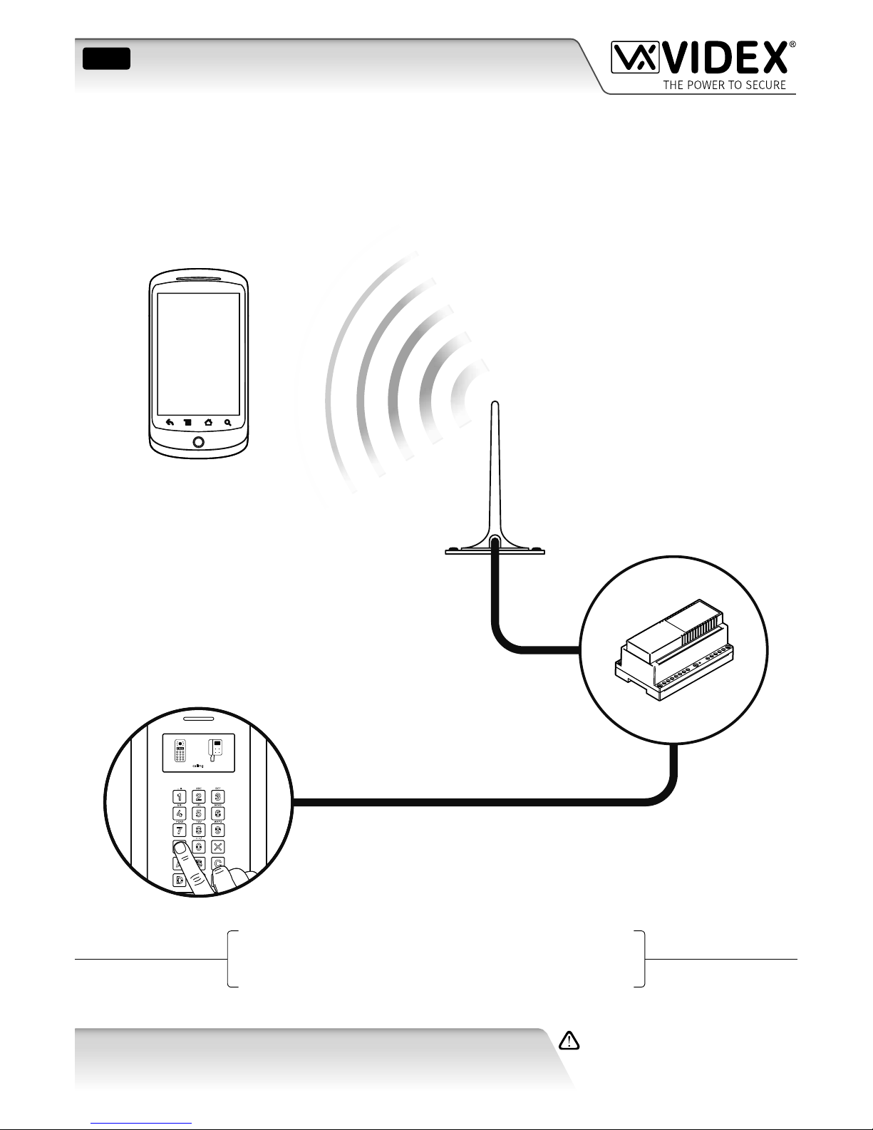
SYSTEM INTRODUCTION
The Art.2270 GSM module is designed to work on the same technology as mobile phones and also interface with the VX2200 digital
2 wire bus system. It enables a call to be made from an entry point (door, gate etc.) to any telephone number (mobile or land line). It
connects directly to the 2 wire bus (L and - databus) and is compatible with the full range of VX2200 intercom panels both functional
and digital and because of this exibility it can be integrated into small or large VX2200 digital systems that also comprises of Videx
audiophones (e.g. Art.3171 etc.) and videophones (e.g. Art.6272 etc.).
It is possible to program up to 180 users where programming is carried out using phones ID’s with each programmed phone ID able
to call four telephone numbers (if the rst is busy or not answered, the call can be diverted to up to three dierent numbers). The GSM
module works on either a 2G or 3G network. Features of the system include:
• Program up to 180 users (phone ID’s 1 to 180) each with 4 programmable telephone numbers (primary and 3 diverts).
• 3 dry contact relay outputs (relay 1, 2 and 3).
• 3 switched 0V auxiliary inputs (A1, A2 and A3).
• 3 programmable automated SMS messages triggered by the auxiliary inputs.
• Apartment alarm signal on the L and - databus which can activate the relays and/or send an SMS message to the master number.
• Dial to Open facility for each relay output (this feature enables up to 1000 stored numbers (000 - 999) per relay to dial into the
GSM module, the module will not answer these calls, but will activate the corresponding relay without being charged for the
call).
• Programmable timeband facility.
• Micro USB connection (for ease of programming using the GSMSK PC software).
• RS485 bus connection (for ease of programming using the GSMSK PC software).
• Integrated bootloader function (for updating the module’s rmware via the GSMSK PC software).
• Event logging system (which can record up to 8000 events).
Programming of the telephone numbers and the additional features can be carried out via text messaging (refer to pages 24 to 33) or
PC using the GSMSK PC software (refer to the GSMSK_66251720_EN_V1-3 software manual or later version).
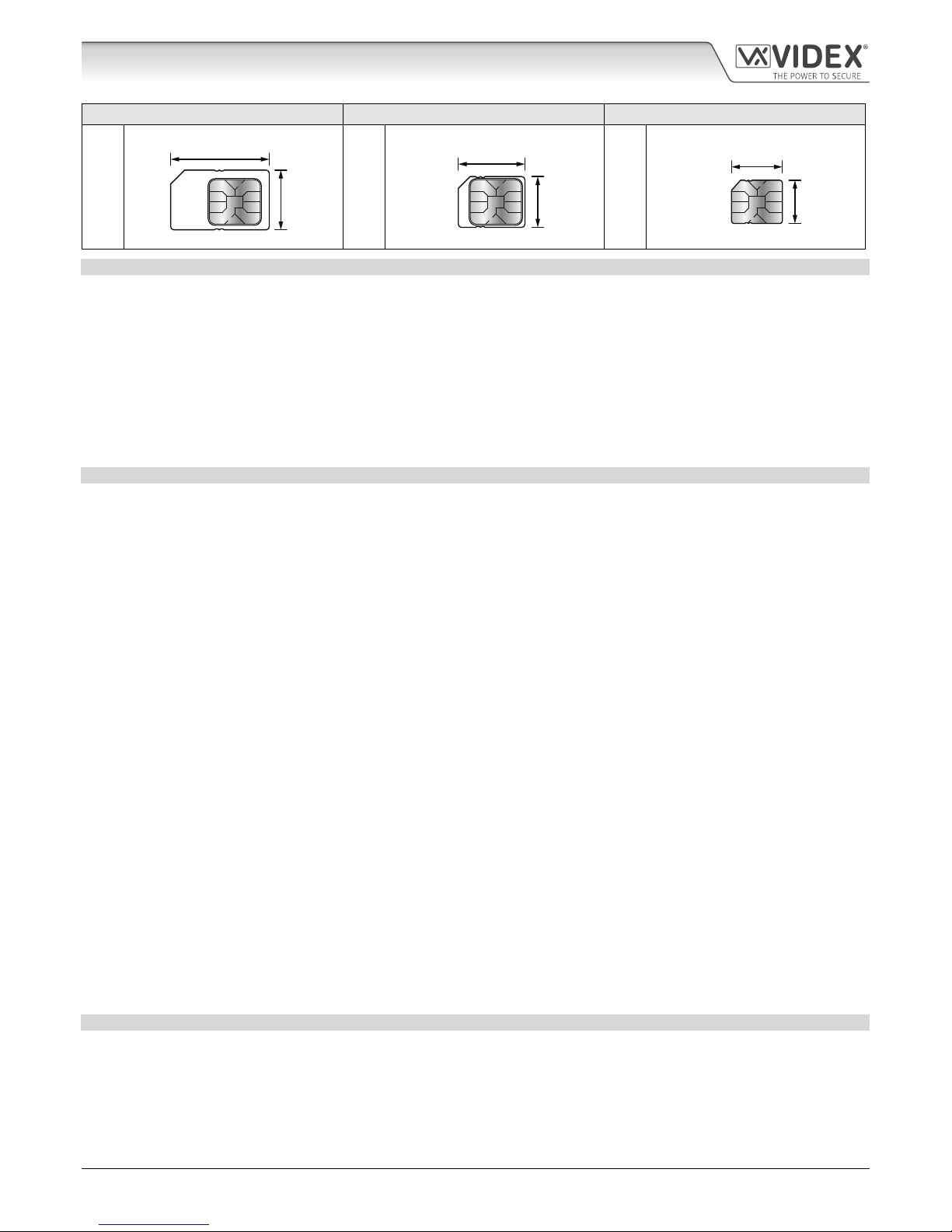
SIM CARD SELECTION
A SIM card is required for this product but not supplied by Videx. The Art.2270 GSM module can only accept a standard size SIM card
(refer to the following SIM card size chart), both a micro-SIM and nano-SIM are not suitable. It is recommended to choose the SIM card
which has the best coverage for the area in which the intercom panel will be installed. Both contract and ‘Pay as you go’ SIM cards can
be used, however if using a ‘Pay as you go’ we would recommend setting up an automatic top up to avoid running short on credit and
losing the use of the intercom panel. Alternatively if you already have a contract mobile phone it should be possible to get a second
SIM card and telephone number on the existing account. For more information contact the SIM card provider or visit their web sites.
Page 5
66251225-EN - V1.0 - 08/01/18
- 5 -
VX2200 GSM Interface Module - Technical Manual
GSM Interface Module for the VX2200 Digital System
Standard SIM Micro-SIM Nano-SIM
;
25mm
15mm
:
15mm
12mm
:
12.3mm
8.8mm
NETWORK PROVIDER SELECTION
It is imperative that for the reliable operation of the system that the best network provider for the area is selected. Problems such as
network disconnection can occur if the provider has signal or interference problems for that area. We would recommend using a GSM
signal strength meter to survey the intended antenna location. Contact Videx for more information on where to purchase a tester.
For UK customers, as an initial check we also recommend visiting the ofcom website www.ofcom.org.uk and follow the onsite links to
their online mobile coverage tool. This tool will advise on the best coverage for the main network providers and other general queries
that you may have about the service provider.
For customers from other countries we suggest to consult the website of the network provider that will be used to check the coverage.
The antenna should always be mounted vertically at the highest point possible. Metal structures and sources of interference such as
power cables, control panels etc. can aect signals and so the antenna should be mounted away from these.
PRECAUTIONARY ADVICE
• When mounting the GSM antenna, choose a location which is away from human interaction and away from the GSM module.
Route the GSM antenna cable from the module so that it is separate from the power supply cables.
• Always ensure the power is switched OFF to the GSM module before inserting or removing the SIM card.
• New SIM cards will need registering with the network service provider before they can be used. Full details of how this is done
can normally be found in the SIM card pack. It will normally require that the SIM card is inserted into a mobile phone, a number
dialled and instructions followed. While the SIM is in the mobile phone it would be a good time to disable any PIN codes, call
diverts, ring back and disable features such as voicemail and text alerts. Details of how to do this can be found on the SIM card
provider’s web site or by calling their customer services. Recommended SIM card providers for the UK are: Vodafone, T-Mobile,
O2 or Orange/EE. For network service providers outside of the UK it is recommended that you consult with the service providers
of your respective country direclty either by telephone or via their website.
• To be able to receive text messages from the GSM module, the SIM card will require an SMS service centre number. This is
normally preinstalled on new SIM cards but if you are having trouble receiving SMS messages you will need to conrm this by
inserting the SIM card into a mobile phone and using the phones menu options to check it. If a number is not programmed then
it should be programmed while in the phone (the number can be obtained from the network service provider).
• Voicemail and text alerts must be switched OFF on the SIM card when using the dial in to release the door/gate feature. For
Vodafone and O2 this can be done while the SIM card is in the GSM module. For Orange/EE, T-Mobile and other providers the
SIM card must be removed from the module, inserted into a mobile phone and the mobile phone menu instructions followed.
This procedure may vary from provider to provider of dierent countires, we suggest contacting your provider for information.
• When storing the GSM module’s telephone number in your own mobile phone avoid using an obvious name such as ‘Front Door,
or ‘My Gate’ as this would make it easy to decipher if your phone was lost or stolen.
• The PIN request feature must be disabled on the SIM card before using it in the module. It is likely on a new SIM card that it will
not be enabled but if it is, it will prevent the system from working at all.
• This product may not be suitable for installation in hospitals, health care facilities or in the presence of ammable gases or liquids.
Seek advice and authorisation before installing this product in these locations. This product is not designed to be used as an
emergency call point.
Network provider and services conguration codes mentioned in this manual are specic for the UK. Please contact the network provider of
your country for the corresponding codes.
IMPORTANT NOTE ABOUT THE SIM
When using a pay monthly SIM card you must ask the service provider to put a spend limit (credit limit) on the account (Vodafone call
this service ‘spend checker’). This is to safeguard against possible problems which could result in a large phone bill at the end of the
month. All providers oer this service. You will need to either ring them or e-mail them to set this up. Automatic top ups should also
have a monthly limit. We would suggest a limit of £50.00 which should be more than enough. This service is not provided by Videx.
Introduction
Page 6
66251225-EN - V1.0 - 08/01/18
- 6 -
VX2200 GSM Interface Module - Technical Manual
GSM Interface Module for the VX2200 Digital System
DESCRIPTION
For the Art.2270 GSM module to work the system requires any intercom panel from the VX2200 range (see table below), a 12Vdc
power supply (DR-15-12 or HDR-15-12, 12Vdc 1.25A), a standard 25mm x 15mm size SIM card (refer to notes on Sim Card Selection
on pages 4 and 5) and a GSM antenna.
Like other devices for the digital VX2200 2 wire bus system the Art.2270 GSM module connects to the 2 wire databus L and -.
Programming of the module can be carried out by sending text (SMS) messages or by using the GSMSK PC software (ver 3.1.0.10 or
later), also refer to the programming manual GSMSK_66251720_EN_V1-3 (or later).
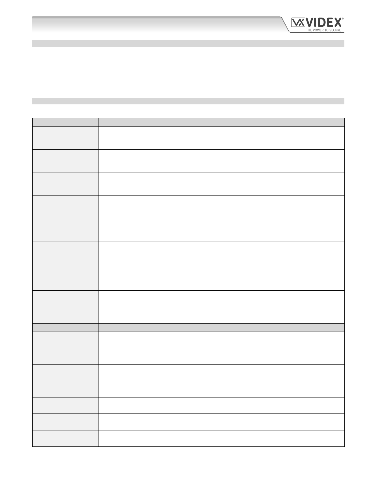
COMPATIBLE VX2200 INTERCOM PANELS
The following table shows the range of VX2200 intercom panels that can be used with the Art.2270 GSM module:
Functional Panel Type Description
Art.4203-n
(audio)
4000 series modular range audio panel, where n = 0, 1, 2, 1D or 2D buttons. When using the Art.42030 the appropriate 4000 series button module(s) will also be required (Art.4842, Art.4842D, Art.4843,
Art.4843D, Art.4844, Art.4844D, Art.4845 and Art.4845D) depending on the size of the system.
Art.4283-n
(audio & video)
4000 series modular range video panel, where n = 0/C, 1/C or 1D/C buttons. When using the Art.42830/C the appropriate 4000 series button module(s) will also be required (Art.4842, Art.4842D, Art.4843,
Art.4843D, Art.4844, Art.4844D, Art.4845 and Art.4845D) depending on the size of the system.
Art.8203-n
(audio)
8000 series modular range audio panel, where n = 0, 1 or 2 buttons. When using the Art.8203-0 the
appropriate 8000 series button module(s) will also be required (Art.8842, Art.8842D, Art.8843, Art.8843D,
Art.8844, Art.8844D, Art.8845 and Art.8845D) depending on the size of the system.
Art.VR4KAM2W-n
(audio)
Vandal Resistant 4000 series modular range audio panel, where n = 0, 1, 2, 3 or 1NP buttons. When using
the Art.VRKAM2W-0 the appropriate VR4K series button module(s) will also be required (Art.VR4KBM-4,
Art.VR4KBM-5, Art.VR4KBM-6, Art.VR4KBM-7, Art.VR4KBM-8, Art.VR4KBM-9, Art.VR4KBM-2NP,
Art.VR4KBM-3NP and Art.VR4KBM-4NP) depending on the size of the system.
VR120/138-n
(audio)
Vandal Resistant VR120 series audio panel, where n = the number of call buttons required (up to 24).
VR120/138-n/CL
(audio + codelock)
Vandal Resistant VR120 series audio panel with codelock facility, where n = the number of call buttons
required (up to 24).
VR120/138-n/PR
(audio + proximity)
Vandal Resistant VR120 series audio panel with proximity reader, where n = the number of call buttons
required (up to 24).
VR120/138-n/V
(audio & video)
Vandal Resistant VR120 series video panel, where n = the number of call buttons required (up to 24).
VR120/138-n/V/CL
(audio & video + codelock)
Vandal Resistant VR120 series video panel with codelock facility, where n = the number of call buttons
required (up to 24).
VR120/138-n/V/PR
(audio & video + proximity)
Vandal Resistant VR120 series video panel with proximity reader, where n = the number of call buttons
required (up to 24).
Digital Panel Type
Description
Art.4202 series
(audio)
4000 series modular range, digital audio panel (with A-F alpha-numeric keypad, Art.4202 or name scroll
facility, Art.4202/R).
Art.4202V series
(audio & video)
4000 series modular range, digital video panel (with A-F alpha-numeric keypad, Art.4202V or name scroll
facility, Art.4202/RV or name scroll facility).
Art.8202 series
(audio)
8000 series modular range, digital audio panel (with A-H alpha-numeric keypad, Art.8202 or name scroll
facility, Art.8202R).
SP300-1 series
(audio)
Vandal Resistant 2200 digital audio panel and bezel box.
SP301-1C series
(audio & video)
Vandal Resistant 2200 digital video panel with colour camera and bezel box.
Art.4212 series
(audio)
Vandal Resistant 4000 series modular range, digital audio panel (with A-F alpha-numeric keypad, Art.4212
or name scroll facility, Art.4212R and proximty). Including Art.4212/UK and Art.4212R/UK.
Art.4212V series
(audio & video)
Vandal Resistant 4000 series modular range, digital video panel (with A-F alpha-numeric keypad,
Art.4212V or name scroll facility, Art.4212RV and proximty). Including Art.4212V/UK and Art.4212RV/UK.
System Components
Page 7
66251225-EN - V1.0 - 08/01/18
- 7 -
VX2200 GSM Interface Module - Technical Manual
GSM Interface Module for the VX2200 Digital System
12VDC 1.25A POWER SUPPLY DR1512 OR HDR1512
The Art.2270 GSM module is designed to work with power supplies in the range
of 12Vdc-13.8Vdc and should be capable of supplying a constant current of no
less than 1A. The recommended power supply to use is the DR-15-12 or the
HDR-15-12, 12Vdc 1.25A power supply, see Fig.1 for model DR-15-12.
Fig. 1
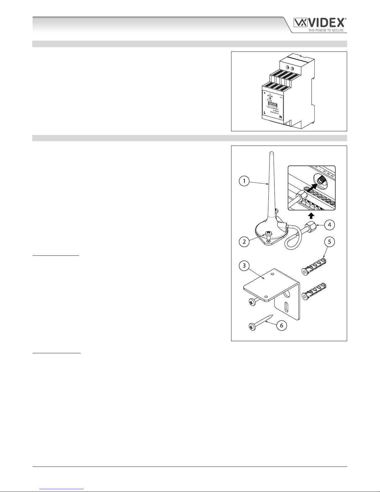
ART. 432 GSM ANTENNA
The Art.432 GSM antenna connects to the SMA female bulkhead connection on the
bottom side of the Art.2270 GSM module (just above the A1 and A2 terminals). A
GSM antenna with an SMA male connector should be used (see to Fig.2).
Antenna Parts
1. GSM antenna with magnetic base.
2. Self-threading screw (Ø3.5mm x 9.5mm).
3. Aluminium L bracket for mounting.
4. SMA male connector (cable length 2.5m).
5. Expansion type wall plugs (Ø6mm).
6. Self-threading screw (Ø4mm x 30mm).
IMPORTANT NOTE: An antenna must always be tted for the Art.2270 GSM
module to work. Always route the GSM antenna cable away from the module to
avoid interference on the speech channels.
Fig. 2
IMPORTANT NOTE: Intercom panel setup and conguration for the compatible panel types listed in the table shown on
page 6 can be found in either the VX2200 technical manual: VX2K2HDIGSYS Version 1.1 (or later) or the relevant installation
instructions that accompany the respective intercom panel.
SMA female bulkhead
connection on the bottom side
of the Art.2270 GSM module
System Components and Available Versions
Page 8
66251225-EN - V1.0 - 08/01/18
- 8 -
VX2200 GSM Interface Module - Technical Manual
GSM Interface Module for the VX2200 Digital System
Technical Information
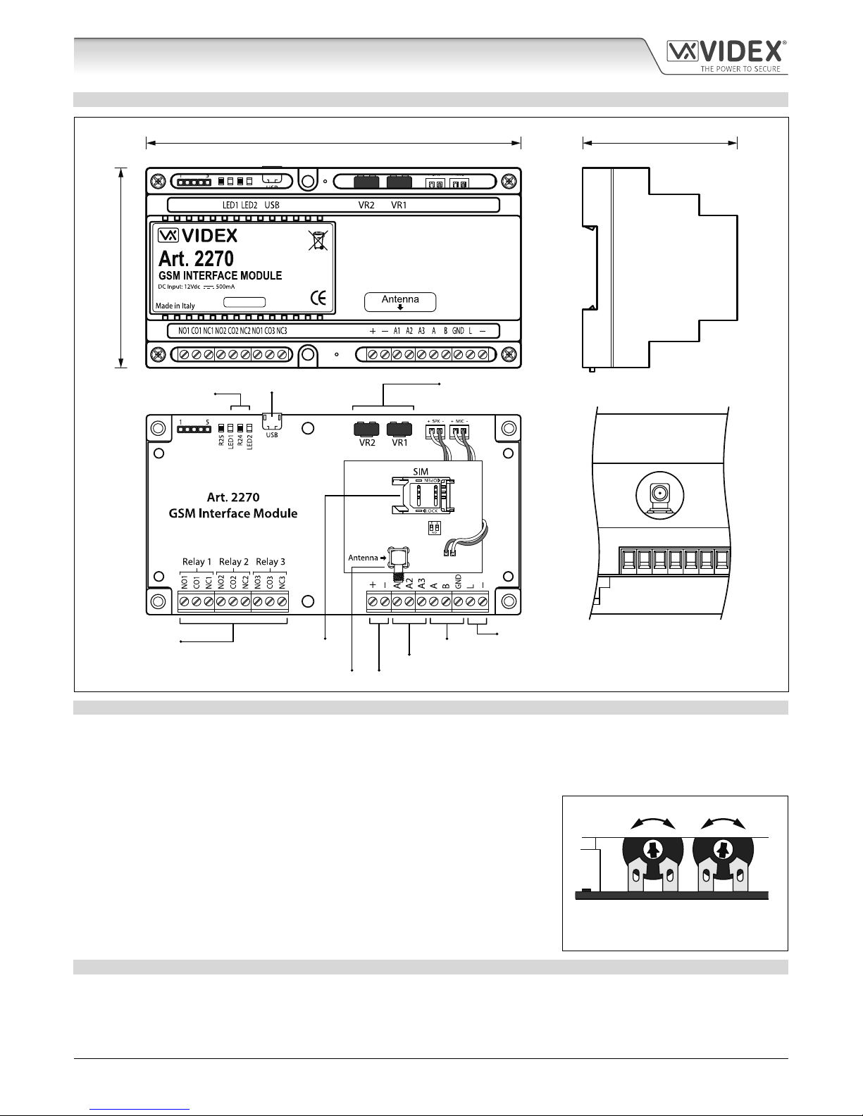
ART. 2270 MODULE
VIDEX
R.1.0
VERMD1.1.0
VIDEX
R.1.0
Antenna connection
side view
157.5mm 65mm
85mm
Fig. 3
MODULE VOLUME ADJUSTMENT POTS VR1 & VR2
There are 2 volume adjustment POT’s located on the top right side of the Art.2270 module, see Fig.3. The VR1 POT control can
be used to adjust the speech volume towards the door panel (panel’s speaker) and the VR2 POT control can be used to adjust
the speech volume towards the telephone line (panel’s microphone). Additionally, the volume can also be adjusted during a call
electronically via the telephone keypad (refer to user command table 1 on page 35).
By default both the VR1 and VR2 adjustment POTs are set to approximately halfway,
see Fig.4.
Speaker Volume Adjustment (speech from phone to panel) - to increase the speaker
volume turn the VR1 POT clockwise (up) and to decrease the speaker volume turn the
VR1 POT anti-clockwise (down).
Microphone Volume Adjustment (speech from panel to phone) - to increase the
microphone volume turn the VR2 POT clockwise (up) and to decrease the microphone
volume turn the VR2 POT anti-clockwise (down).
VR1 VR2
DOWN UPDOWN UP
Fig. 4
USB CONNECTION
The micro-USB connection allows the Art.2270 module to be connected to a laptop/PC for ease of programming (refer to page 18
for connecting the GSM module to a laptop/PC). Further information on programming using the GSMSK PC software can be found
in the following manual: GSMSK_66251720_EN_V1-3 (or later version).
Status indication LED's
Power terminal connections
Auxiliary terminal connections
RS485 bus connection
Databus terminal connections
Relay terminal
connections
Antenna connection
SIM card holder
VR1 & VR2 speech
volume control POT’s
Micro USB connection
Page 9
66251225-EN - V1.0 - 08/01/18
- 9 -
VX2200 GSM Interface Module - Technical Manual
GSM Interface Module for the VX2200 Digital System
TERMINAL CONNECTIONS
Terminal Description
NO1 Normally open 1 relay contact.
Relay 1, 2 and 3 contacts:
3A@24Vdc
3A@120Vac
CO1 Common 1 relay contact.
NC1 Normally closed 1 relay contact.
NO2 Normally open 2 relay contact.
CO2 Common 2 relay contact.
NC2 Normally closed 2 relay contact.
NO3 Normally open 3 relay contact.
CO3 Common 3 relay contact.
NC3 Normally closed 3 relay contact.
+ +12Vdc power input (500mA max.)
– 0V ground power.
A1 Auxiliary 1 input (triggers relay 1 when A1 mode set to 000, switched 0V, default).
A2 Auxiliary 2 input (triggers relay 2 when A2 mode set to 000, switched 0V, default).
A3 Auxiliary 3 input (triggers relay 3 when A3 mode set to 000, switched 0V, default).
A
RS485 bus connection (for ease of programming and permanent connection for monitoring purposes).B
GND
L BUS line data input.
– BUS line ground input.
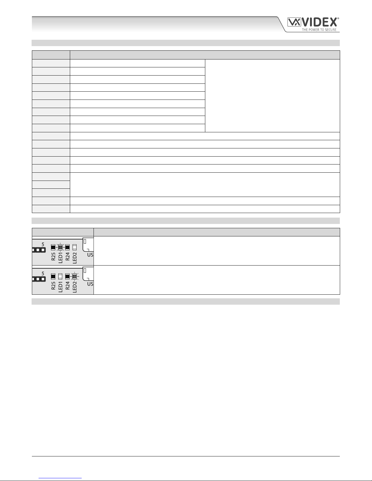
STATUS INDICATION LED’S
LED Description
During ‘power up’ the red LED (LED1) will ash continuously while trying to connect the Art.2270
module to the network. As soon as the module is connected to the network it will switch OFF. The
LED will also switch ON whenever the line is in use or the module is busy and will ash whenever the
network connection is lost and is trying to re-establish a connection.
The green LED (LED2) will ash whenever it sees data on the L and - bus connection (when the Art.2270
module is in use). The LED will switch ON and stay ON during communication via the USB or RS485 bus
connection. In standby when the module is not in use the LED will be switched OFF.
TECHNICAL SPECIFICATION
Working Voltage : 12Vdc +/- 10%
Standby Current : approx. 60mA
Max. Current : approx. 500mA (max.)
Phone ID’s (call buttons) : 1 up to 180 (max.)
Telephone Numbers per ID : 4 telephone numbers (1 primary, 3 diverts)
Dial to Open Numbers : up to 1000 per relay (max.), 3000 DTO numbers in total
Status Indication LED’s : 2 (red LED1 power up/busy, green LED2 data)
Programming : SMS messaging or PC software
Auxiliary Inputs : 3 (A1, A2 and A3 switched 0V input)
Dry Contact Relay : 3 (relay 1, 2 and 3), 3A @ 24Vdc, 3A @ 120Vac
Event Log : up to 8000 events
USB Port : micro USB
RS485 Bus Connection : A, B and GND
Timebands : 1 programmable timeband
Dimensions : 157.5mm (W) x 85mm (L) x 65mm (D)
Working Temp. : -10 +50
o
C
Technical Information
Page 10
66251225-EN - V1.0 - 08/01/18
- 10 -
VX2200 GSM Interface Module - Technical Manual
GSM Interface Module for the VX2200 Digital System
Wiring Diagrams
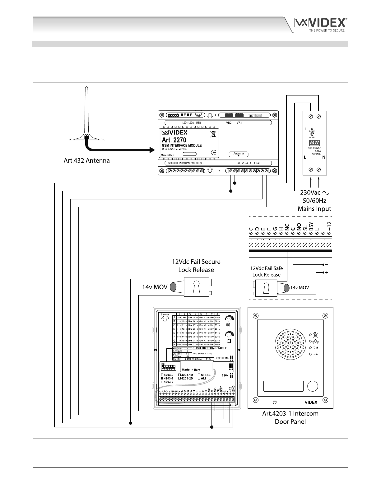
FUNCTIONAL INTERCOM PANEL CONNECTIONS
The following wiring diagram, Fig.5, shows the wiring connections for a functional panel, in this example an Art.4203-1 (speaker)
functional panel. The wiring conguration of the panel’s buttons can be found in the following technical manual: VX2K2HDIGSYS
Version 1.1 or the relevant installation instructions that come with the speaker module. The same wiring diagram can also be used
for other series functional panels.
1
VIDEX
R.1.0
VERMD1.1.0
Fig. 5
A fail secure lock release is shown, for fail safe lock release connections move the lock wire from normally open (NO) across to
terminal normally closed (NC) on the speaker module, as shown in Fig.5.
Page 11
66251225-EN - V1.0 - 08/01/18
- 11 -
GSM Interface Module for the VX2200 Digital System
VX2200 GSM Interface Module - Technical Manual
Wiring Diagrams
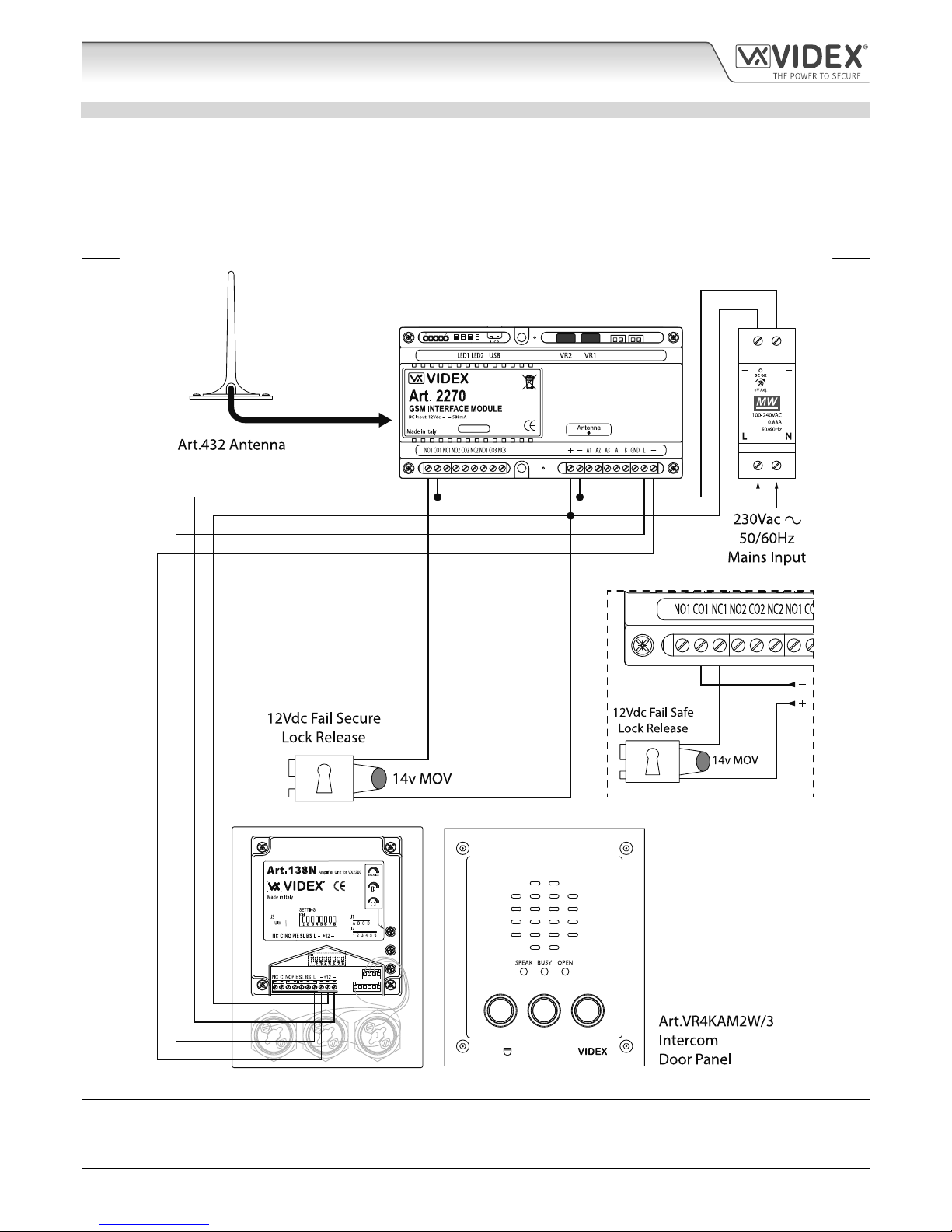
FUNCTIONAL INTERCOM PANEL CONNECTIONS SECURED BY DESIGN LOCK WIRING
The following wiring diagram, Fig.6 similar to Fig.5 shown on page 10, shows the wiring connections for a functional panel, in this
example an Art.VR4KAM2W (Art.138N speaker) functional panel. To meet the Secured by Design specication the lock release
is connected directly from the relay output (in this example relay 1) on the GSM module. The GSM module would be located in a
secure location away from the intercom door panel with only the connections for the L and - databus and power connections. The
wiring conguration of the panel’s buttons can be found in the following technical manual: VX2K2HDIGSYS Version 1.1 or the
relevant installation instructions that come with the speaker module. The same wiring diagram can also be used for other series
functional panels.
123
1
3
VIDEX
R.1.0
VERMD1.1.0
Fig. 6
A fail secure lock release is shown, for fail safe lock release connections move the lock wire from normally open (NO1) across to
terminal normally closed (NC1) as shown in Fig.6. The same method of wiring locks can be applied to relay 2 and relay 3.
Page 12
66251225-EN - V1.0 - 08/01/18
- 12 -
VX2200 GSM Interface Module - Technical Manual
GSM Interface Module for the VX2200 Digital System
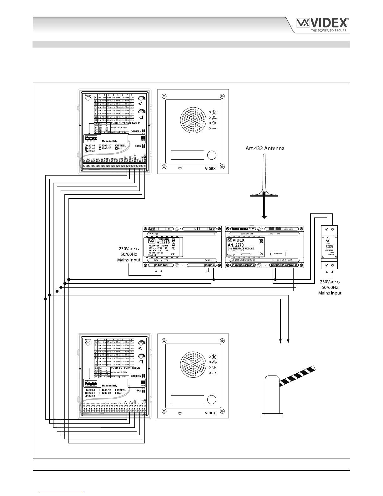
FUNCTIONAL INTERCOM PANEL CONNECTIONS DUAL HEIGHT BARRIER EXAMPLE
The following wiring diagram, Fig.7, shows the connections for two functional panels as a “dual-height barrier” conguration, in
this example two Art.4203-1 (speaker) panels with volt free connections to a set of barrier controls. The wiring conguration of the
panel’s buttons can be found in the following technical manual: VX2K2HDIGSYS Version 1.1 or the relevant installation instructions
that come with the speaker module. The same wiring diagram can also be used for other series functional panels.
1
1
Art.4203-1 Lower Level
Intercom Panel
(MASTER, DEVICE 1)
Art.4203-1 Upper Level
Intercom Panel
(SLAVE, DEVICE 2)
VIDEX
R.1.0
VERMD1.1.0
VIDEX
R.1.0
Volt Free Relay Contacts
to Barrier Input Controls
Fig. 7
Wiring Diagrams
Page 13
66251225-EN - V1.0 - 08/01/18
- 13 -
GSM Interface Module for the VX2200 Digital System
VX2200 GSM Interface Module - Technical Manual
Wiring Diagrams
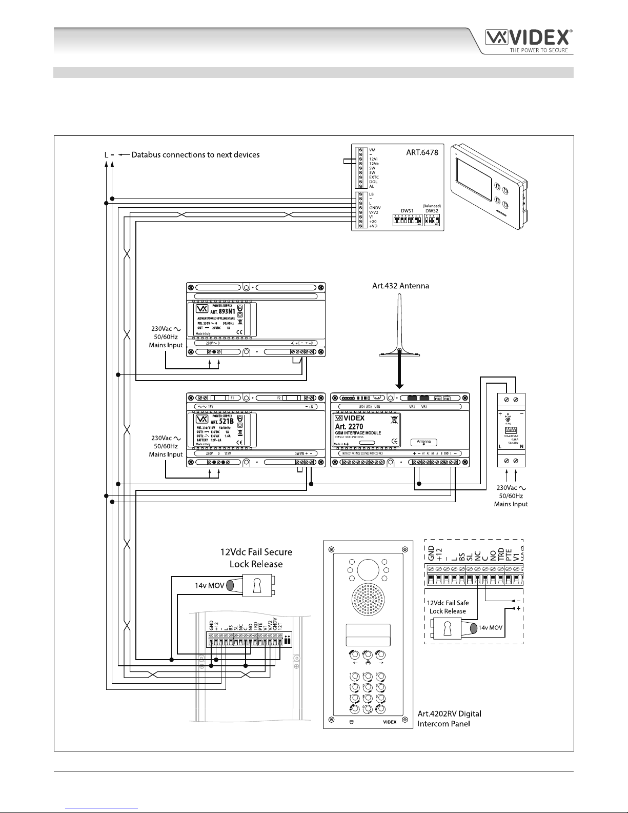
DIGITAL INTERCOM PANEL CONNECTIONS
The following wiring diagram, Fig.8, shows the connections for a digital panel, in this example an Art.4202RV digital panel with
other connections for an Art.6478 videophone. The VX2200 system setup, conguration and the digital panel’s programming can
be found in the following technical manual: VX2K2HDIGSYS Version 1.1. For the Art.6478 setup and conguration refer to the
installation instructions: 66251320-EN-V1.5.
VIDEX
R.1.0
VERMD1.1.0
VIDEX
R.1.0
VIDEX
R.1.0
Fig. 8
Page 14
66251225-EN - V1.0 - 08/01/18
- 14 -
VX2200 GSM Interface Module - Technical Manual
GSM Interface Module for the VX2200 Digital System
Wiring Diagrams
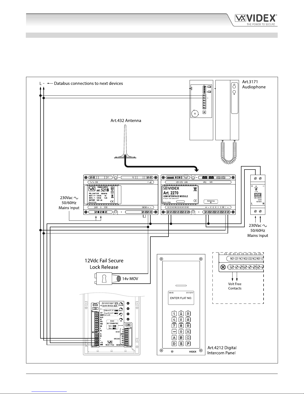
DIGITAL INTERCOM PANEL CONNECTIONS SECURED BY DESIGN LOCK WIRING
The following wiring diagram, Fig.9, shows the connections for a digital panel, in this example an Art.4212 digital panel with
other connections for standard Art.3171 audiophones. To meet the Secured by Design specication the lock release is connected
directly from the relay output (in this example relay 1) on the GSM module. The GSM module would be located in a secure location
away from the intercom door panel with only the connections for the L and - databus and power connections. The digital panel’s
programming can be found in the following installation instructions: 66250203-EN-V0.7 and for the VX2200 system setup and
conguration the technical manual: VX2K2HDIGSYS Version 1.1.
For volt free connections connect wires
into CO1 and NO1 terminals. For Fail Safe
connections refer to Fig.6.
VIDEX
R.1.0
VERMD1.1.0
VIDEX
R.1.0
VIDEX
VR1
L
LB
AL
SW
SW
Fig. 9
Page 15

66251225-EN - V1.0 - 08/01/18
- 15 -
VX2200 GSM Interface Module - Technical Manual
GSM Interface Module for the VX2200 Digital System
Auxiliary Inputs & Relay Outputs
The Art.2270 module’s auxiliary modes (A1M, A2M and A3M) can be programmed to 7 dierent modes (000 - 006), please refer to
programming notes on how to set up the auxiliary output modes on page 27. The auxiliary modes can also be programmed using
the GSMSK PC software, please refer to programming manual GSMSK_66251720_EN_V1-3 (or later version).
AUXILIARY A1M, A2M AND A3M SET TO MODE 000 TRIGGERS RESPECTIVE RELAY 1, 2 OR 3
The example shown in Fig.10 shows the connection for auxiliary A1 when the A1M mode is set to 000 (default mode). When
auxiliary input A1 is triggered by a switched 0V signal it will activate relay 1 for the programmed relay 1 time R1T (also refer to
programming notes for auxiliary mode set up and setting relay 1, 2 and 3 times). The auxiliary mode setup can also be applied for
A2M and A3M and will activate their respective relays (i.e. A2 input for relay 2 and A3 input for relay 3).
VIDEX
R.1.0
VERMD1.1.0
When the auxiliary A1 mode (A1M) is set
to mode 000 (default). Relay 1 will activate
for the programmed relay 1 time (R1T)
when A1 input is triggered.
Relay 2 activates on A2 trigger when A2M = 000
Relay 3 activates on A3 trigger when A3M = 000
A2 input
(switched 0V)
A3 input
(switched 0V)
A1 input
(switched 0V)
Fig. 10
AUXILIARY A1M, A2M AND A3M SET TO MODE 001 SEND SMS MESSAGE TO MASTER NUMBER
The example shown in Fig.11 shows the connection for auxiliary A1 when the A1M mode is set to 001. When auxiliary input A1
is triggered by a switched 0V signal it will send the SMS message stored for S1S to the master number (also refer to programming
notes for auxilairy mode set up, storing SMS 1, 2 and 3 messages and storing a master number). The auxiliary mode setup can also
be applied for A2M and A3M and will send their respective SMS messages to the master number (i.e. A2 input for S2S message and
A3 input for S3S message). Please note the maximum length of each SMS message can be up to 32 characters.
VIDEX
R.1.0
VERMD1.1.0
A2 input
(switched 0V)
A3 input
(switched 0V)
A1 input
(switched 0V)
D1.
When the auxiliary A1 mode (A1M) is set to mode 001, S1S message
(Aux 1 message) sent to master number when A1 input triggered.
When A2M = 001, S2S message sent when A2 input triggered.
When A3M = 001, S3S message sent when A3 input triggered.
Fig. 11
Page 16

66251225-EN - V1.0 - 08/01/18
- 16 -
VX2200 GSM Interface Module - Technical Manual
GSM Interface Module for the VX2200 Digital System
Auxiliary Inputs & Relay Outputs
AUXILIARY A1M, A2M AND A3M SET TO MODE 002 TRIGGERS RESPECTIVE RELAY FOR DURATION OF CALL
The example shown in Fig.12 shows the connection for relay 1 when the A1M mode is set to 002. Relay 1 will activate at the
beginning of the call and last for the duration of the call (also refer to programming notes for auxiliary mode set up). The auxiliary
mode setup can also be applied for A2M and A3M and will activate their respective relays (i.e. A2M for relay 2 and A3M for relay 3).
VIDEX
R.1.0
VERMD1.1.0
When the auxiliary A1 mode (A1M) is set
to mode 002, relay 1 will activate at the
beginning of the call and last for the
duration of the call. When the call ends
relay 1 will deactivate.
Relay 2 activates for the call duration, when
A2M = 002 and deactivates when the call ends.
Relay 3 activates for the call duration, when
A3M = 002 and deactivates when the call ends.
Fig. 12
AUXILIARY A1M, A2M AND A3M SET TO MODE 003 TRIGGERS RESPECTIVE RELAY FOR THE PROGRAMMED RELAY TIME
The example shown in Fig.13 shows the connection for relay 1 when the A1M mode is set to 003. Relay 1 will activate at the
beginning of the call for the programmed relay 1 time R1T (also refer to programming notes for auxiliary mode set up and setting
relay 1, 2 and 3 times). The auxiliary mode setup can also be applied for A2M and A3M and will activate their respective relays for
their respective relay times (i.e. A2M for relay 2 time R2T and A3M for relay 3 time R3T).
VIDEX
R.1.0
VERMD1.1.0
When the auxiliary A1 mode (A1M) is set
to mode 003, relay 1 will activate at the
beginning of the call for the programmed
relay 1 time R1T.
Relay 2 activates at the beginning of the call for
the programmed R2T time when A2M = 003.
Relay 3 activates at the beginning of the call for
the programmed R3T time when A3M = 003.
Fig. 13
Page 17

66251225-EN - V1.0 - 08/01/18
- 17 -
VX2200 GSM Interface Module - Technical Manual
GSM Interface Module for the VX2200 Digital System
AUXILIARY A1M, A2M AND A3M SET TO MODE 004 TRIGGERS RESPECTIVE RELAY BY APARTMENT ALARM
The example shown in Fig.14 shows the connections for relay 1 and the L and - databus when the A1M mode is set to 004. When
the Art.2270 module receives an apartment alarm signal on the databus relay 1 will activate for the programmed relay 1 time R1T
(also refer to programming notes for auxiliary mode set up and setting relay 1, 2 and 3 times). The auxiliary mode setup can also be
applied for A2M and A3M and will activate their respective relays for their respective relay times (i.e. A2M for relay 2 time R2T and
A3M for relay 3 time R3T).
VIDEX
R.1.0
VERMD1.1.0
When the auxiliary A1 mode (A1M) is set to mode
004, relay 1 will activate for the programmed relay
1 time R1T when an apartment alarm signal is
received on the L and - databus.
Relay 2 activates for the programmed R2T time when A2M =
004 and an apartment alarm signal is received on the databus.
Relay 3 activates for the programmed R3T time when A3M =
004 and an apartment alarm signal is received on the databus.
Apartment
alarm databus
signal
Fig. 14
AUXILIARY A1M, A2M AND A3M SET TO MODE 005 SEND SMS MESSAGE TO MASTER NUMBER WHEN TRIGGERED BY
APARTMENT ALARM
The example shown in Fig.15 shows the connections for the L and - databus when the A1M mode is set to 005. When the Art.2270
module receives an apartment alarm signal on the databus the GSM module will send the SMS message stored for S1S to the
master number (also refer to programming notes for auxilairy mode set up, storing SMS 1, 2 and 3 messages and storing a master
number). The auxiliary mode setup can also be applied for A2M and A3M and will send their respective SMS messages to the master
number (i.e. A2M for S2S message and A3M for S3S message). Please note the maximum length of each SMS message can be up
to 32 characters.
VIDEX
R.1.0
VERMD1.1.0
When the auxiliary A1 mode (A1M) is set to
mode 005, S1S message (Aux 1 message)
When A2M = 005, S2S message sent when apartment alarm signal received on databus.
When A3M = 005, S3S message sent when apartment alarm signal received on databus.
sent to master number when when an apartment
alarm signal is received on the L and - databus.
Apartment
alarm databus
signal
Fig. 15
Auxiliary Inputs & Relay Outputs
Page 18

66251225-EN - V1.0 - 08/01/18
- 18 -
VX2200 GSM Interface Module - Technical Manual
GSM Interface Module for the VX2200 Digital System
Auxiliary Inputs & Relay Outputs
AUXILIARY A1M, A2M AND A3M SET TO MODE 006 RELAY 1, 2 OR 3 TRIGGERED BY DOOR ID 1, 2 OR 3 RESPECTIVELY
The example shown in Fig.16 shows the connection for relay 1 when the A1M mode is set to 006. After a call has been made and
answered at an apartment (whether it is a programmed telephone number for an apartment or a call made to a Videx audiophone/
videophone in an apartment) and the intercom panel’s ID (door ID) has been set to ID.1 the panel’s onboard relay will trigger as
expected, but also relay 1 on the Art.2270 GSM module will activate for the programmed relay 1 time R1T when the lock release
signal has been triggered (also refer to programming notes for auxiliary mode set up and setting relay 1, 2 and 3 times). The auxiliary
mode setup can also be applied for A2M and A3M and will activate their relays for their respective relay times (i.e. A2M for relay 2
time R2T for door ID.2 and A3M for relay 3 time R3T for door ID.3). For setting up the intercom panel’s relay time and door ID refer
to the relevant installation instructions that acompany the intercom panel.
1
Panel’s door
ID set to ID.1
VIDEX
R.1.0
VERMD1.1.0
When the auxiliary A1 mode (A1M) is set to mode 006 and the intercom panel has been setup as ID.1, the
panel’s onboard relay will trigger as normal and relay 1 on the GSM module will activate for the programmed
R1T time when the lock release signal has been triggered during a call (from either a programmed telephone
number or a Videx audiophone/videophone).
Fig. 16
IMPORTANT NOTE: Only one mode can be set for each auxiliary input (A1, A2 or A3) at any one time, however each individual
auxiliary mode can be set dierently e.g. auxiliary A1M could be set to mode 001, auxiliary A2M could be set to mode 003 and
auxiliary A3M could be set to mode 006.
When any of the auxiliary modes A1M, A2M and A3M are set to mode 002 - 006 the auxiliary inputs A1, A2 and A3 can still
activate their respective relays 1, 2 and 3 for the programmed relay times R1T, R2T and R3T as if in mode 000.
Mode 006 is only applicable for intercom panel door ID’s 1, 2 and 3.
Page 19

66251225-EN - V1.0 - 08/01/18
- 19 -
VX2200 GSM Interface Module - Technical Manual
GSM Interface Module for the VX2200 Digital System
USB & RS485 Connection
CONNECTIONS TO A PC
The Art.2270 GSM module also includes two options for connecting to a PC: via a USB connection or via an RS485 connection. Both
methods of connection are to allow for ease of programming and monitoring using the GSMSK PC software. All programming
features described in this manual are also accessible using the software. Further information on using the GSMSK PC software can
be found in the technical manual GSMSK_66251720_EN_V1-3 (or later version).
OPTION 1: USB CONNECTION
The GSM module can be connected using a standard micro-USB to USB cable as shown in Fig.17. This method of connection is
primarily used for programming and setup of the GSM module only.
VIDEX
R.1.0
PC
Fig. 17
OPTION 2: RS485 CONNECTION
The GSM module can also be connected using an RS485 bus connection via an RS485 to USB converter (Art.481) as shown in
Fig.18 in instances where a permanent connection to a PC is required for monitoring purposes and downloading event logs. When
connected in this way the GSM module can only be connected as a ‘one-to-one’ bus connection to the PC, another GSM module
cannot be connected on the same RS485 bus to the PC.
VIDEX
R.1.0
485 / 232
RS-485
USB-PC
A B GND
RS-232
Art. 481
USB-Serial Converter
Open
Close
BUS
Termination
PC
Fig. 18
*For end of line termination a 120 Ohm resistor must be tted across the RS485 terminals A and B, as shown in Fig.17.
Page 20

66251225-EN - V1.0 - 08/01/18
- 20 -
VX2200 GSM Interface Module - Technical Manual
GSM Interface Module for the VX2200 Digital System
CABLE SIZE GUIDE
Refer to the table below for the connections for the power supply output to the GSM module and the lock release connections.
Distance 20m 50m 100m
Cross Sectional Area (CSA) 0.5mm
2
1.0mm
2
1.5mm
2
Ideally the power supply should be located as close to the intercom panel as possible for best performance. The maximum
acceptable resistance for the above cables = 3Ω or less for best possible performance.
For other VX2200 system devices refer to the following table. It is recommended that a twisted pair cable is used for the L and databus connections and for balanced video signal connections V1 and V2 (for video systems).
VX2200 System Cable Requirements
Connections 50m 100m 200m 300m
L 0.4mm
2
0.5mm
2
0.75mm
2
1.0mm
2
- 0.4mm
2
0.5mm
2
0.75mm
2
1.0mm
2
V1 * 0.35mm
2
0.5mm
2
0.75mm
2
1.0mm
2
V2 * 0.35mm
2
0.5mm
2
0.75mm
2
1.0mm
2
+20V * 0.5mm
2
0.75mm
2
1.0mm
2
1.5mm
2
GNDV * 0.5mm
2
0.75mm
2
1.0mm
2
1.5mm
2
+12V 0.4mm
2
0.75mm
2
1.0mm
2
1.5mm
2
GND 0.4mm
2
0.75mm
2
1.0mm
2
1.5mm
2
All others ** 0.25mm
2
0.35mm
2
0.5mm
2
0.75mm
2
* - these connections are only required on video systems.
** - these are optional connections (e.g. door monitoring LED).
The maximum acceptable resistance for all the above connections (except +20V and GNDV) = 7.5 Ohms or less and the maximum
acceptable resistance for the video connections +20V and GNDV = 5 Ohms or less for best possible performance. Please note that
all cable sizes shown in the tables above are the minimum cable requirements.
IMPORTANT NOTE: Only bare copper (BC) cable should be used (solid or stranded is acceptable). Please be aware that when
selecting a cable the following should NOT be used: Copper Coated Steel (CCS) and Copper Clad Aluminium (CCA). While these
types of cable may oer a low cost solution they will have a higher resistance than pure copper cable and can aect the overall
performance of the system therefore Videx DO NOT recommend these types of cable.
Further cabling information can be found the technical manual VX2200Blocks1-2 and is also provided in any acompanying
installation instructions with the various VX2200 system components.
GENERAL INSTALLATION NOTES
• Check that all components are free from damage before installing (do not proceed with installation in the event of damage).
• Keep all packaging away from children.
• Do not obstruct the ventilation openings or slots on any of the devices.
• All connections to mains voltages must be made to the current national standards (I.E.E. wiring regulations for the UK or
the appropriate standards of your country).
• Install an appropriate fused spur or isolation switch to isolate the mains.
• Isolate the mains before carrying out any maintenance work on the system.
• Avoid water ingress into the rear of the module, always seal the module frame after installation using a suitable silicon
based sealant.
• All intercom and access control cables must be routed separately from the mains.
General Directions for Installation
Page 21

66251225-EN - V1.0 - 08/01/18
- 21 -
VX2200 GSM Interface Module - Technical Manual
GSM Interface Module for the VX2200 Digital System
General Directions for Installation
LOCK RELEASE WIRING AND BACK EMF PROTECTION
When tting an electric lock release back EMF protection will be required. If tting an AC lock release then a 100nF ceramic disc
capacitor must be tted across the terminals of the lock, shown in Fig.19. If tting a DC lock release (fail secure or fail safe) then a
1N4002 diode must be tted across the terminals on the lock, shown in Fig.20.
100nF CAP
+
-
1N4002 DIODE
Fig. 19 Fig. 20
If a 100nF ceramic disc capacitor or a 1N4002 diode are not available then a 14 - 20V MOV (metal oxide varistor) can be tted across
the lock terminals instead (refer to Fig.19 above) and can be tted on both an AC and DC lock. Connection examples can also be
seen on the wiring diagrams on pages 10 to 14.
CONNECTION TO MAINS, SAFETY AND GUIDANCE NOTES
IMPORTANT: PLEASE READ THESE INSTRUCTIONS CAREFULLY BEFORE COMMENCING WITH THE INSTALLATION.
Videx recommends that any cabling and Videx product be installed by a competent and qualied electrician, security installation
speclialist or communications engineer.
• DO NOT install any Videx product in areas where the following may be present or occur:
• Excessive oil or a grease laden atmosphere.
• Corrosive or ammable gases, liquids or vapours.
• Possible obstructions which would prevent or hinder the access and/or removal of the Videx product.
MAINS CONNECTION
The system MUST be installed in accordance with the current I.E.E regulations (in particular I.E.E. Wiring regulations BS7671 for the
UK), or the appropriate standards of your country, in particular Videx recommends:
• Connecting the system to the mains through an all-pole circuit breaker (refer to Fig.21) which shall have contact separation
of at least 3mm in each pole and shall disconnect all poles simultaneously.
• That the all-pole circuit breaker shall be placed in such a way to allow for easy access and the switch shall remain readily
operable.
• Ensuring that the mains supply (Voltage, Frequency and Phase) complies with the product rating label.
• Isolating the mains before carrying out any maintenance work on the system.
FUSE
N
L
Mains
1 PHASE SUPPLY
(220 - 240Vac, 50/60Hz)
SWITCHED FUSE SPUR
Fig. 21
Page 22

66251225-EN - V1.0 - 08/01/18
- 22 -
VX2200 GSM Interface Module - Technical Manual
GSM Interface Module for the VX2200 Digital System
POWER SUPPLY INSTALLATION AND MOUNTING
Follow the steps below when tting the DL-15-12, Art521B or Art.893N1 DIN type power supply.
• First remove the terminal side covers by unscrewing the retaining screws (if applicable).
• Fix the power supply to a DIN rail (following Fig.22, Fig.23 and Fig.24).
• Switch OFF the mains using the circuit breaker (mentioned previously) and then make the connections as shown on the
installation (wiring) diagrams.
• Check the connections and secure the wires into the terminals ensuring that the low voltage (signal) cables are routed
separately from the high voltage (mains) cables.
• Replace the terminal covers and x them back into place using the relevant screws (if applicable).
• When all connections are made restore the mains supply.
Fig. 22 Fig. 23
Fig. 24
MOUNTING THE ART.2270 GSM MODULE
The Art.2270 GSM module can also be mounted following the same instructions for mounting a DIN type power supply (described
above following Fig.22, Fig.23 and Fig.24) and then making the necessary terminal connections shown in the wiring diagrams on
pages 10 -14 (depending on the system setup and conguration).
IMPORTANT NOTE: When tting the SIM card into the GSM module the module itself must be tted to the DIN rail as described
above rst. Once mounted on the DIN rail the top cover can be removed by unscrewing the 4 retaining screws to gain access to
the SIM card holder pcb. Also refer to Fitting the SIM & Connecting Power notes on page 23.
General Directions for Installation
Page 23

66251225-EN - V1.0 - 08/01/18
- 23 -
VX2200 GSM Interface Module - Technical Manual
GSM Interface Module for the VX2200 Digital System
Fitting the SIM & Connecting Power
FITTING THE SIM CARD AND CONNECTING THE POWER TO THE ART.2270 GSM MODULE
After installing the power supply, antenna, lock output and any other devices required (following the wiring diagrams on pages 10 - 14)
and before powering the system up, a registered SIM card must be tted into the SIM holder on the top side of the GSM module. A SIM
card from most network providers can be used, also refer to notes on SIM card selection on pages 4 and 5. Follow the steps below to
insert the SIM card.
1. First remove the top cover of the Art.2270 module (as
described on page 21) to gain access to the SIM holder
pcb.
2. On the SIM holder pcb, slide the SIM holder to the right
until it ‘clicks’, as shown in Fig.25.
3. The SIM holder is hinged and will open out to the right,
see Fig.26.
4. Place the SIM card into the holder (it will only t one
way, see Fig.27) and fold the holder back down, see
Fig.28.
5. Slide the SIM holder back to the leftt until it ‘clicks’, see
Fig.29).
6. Once the SIM is in place make any other necessary
terminal connections on the GSM module that may be
required.
7. Connect the Art.432 GSM antenna and then connect
the 12Vdc power supply wires but DO NOT power up
the system yet.
8. Follow the initialisation process for the Art.2270 GSM
module described below.
Fig. 25 Fig. 26
Fig. 27 Fig. 28
Fig. 29
POWER UP INITIALISATION SEQUENCE FOR THE ART.2270 GSM MODULE
The Art.2270 GSM module requires approximately 20 seconds to initialise properly. We recommend NOT sending SMS messages or
pressing buttons on the intercom panel during this time.
1. First check all the connections have been made correctly and then power up the system.
2. The red LED (LED1) will switch ON for approximately 5 seconds, as shown in Fig.30.
3. After this the red LED (LED1) will continue to ash while it registers with the chosen network, as shown in Fig.31.
4. After a further delay the red LED (LED1) will stop ashing, as shown in Fig.32, to indicate that the GSM module has registered
with the network and is ready to begin programming.
5 secs...
Fig. 30 Fig. 31 Fig. 32
Page 24

66251225-EN - V1.0 - 08/01/18
- 24 -
VX2200 GSM Interface Module - Technical Manual
GSM Interface Module for the VX2200 Digital System
Reset Procedure
RESETTING THE ART.2270 GSM MODULE TO FACTORY DEFAULTS
There are two reset options for the GSM module. The rst will reset the master code only (any programming will be retained in the
GSM module) and the second will reset everything and clear all stored telephone numbers and reset all settings.
RESETTING THE MASTER CODE TO 1111 4x1
1. Ensure the power is switched OFF to the GSM module;
2. Short out the auxiliary terminal A1 to the - terminal with a piece of link wire, see
Fig.33;
3. Switch the power back ON to the GSM module, the red LED (LED1) will switch ON
for approximately 8 seconds;
4. The red LED (LED1) will then start to ash for approximately 60 seconds while it
resets the master code back to 1111 (4x1), as shown in Fig.34;
5. After the 60 seconds is up the red LED (LED1) will stop ashing, remove the short
between A1 and the - terminal. The master code has been rest back to 1111 (4x1)
and the GSM module is ready for programming.
IMPORTANT NOTE: When a master code reset is performed on the GSM module it
will only reset the 4 digit programming code back to factory default 1111, all the
settings and programmed information (telephone numbers etc.) will still be stored
in the GSM module. No attempt should be made to remove the short before the red
LED (LED1) stops ashing otherwise the master code reset will not work.
Fig. 33
Fig. 34
FULL SYSTEM RESET
1. Ensure the power is switched OFF to the GSM module;
2. Short out the auxiliary terminals A2 and A3 to the - terminal with a piece of link
wire, see Fig.35;
3. Switch the power back ON to the GSM module, initially the red LED (LED1) will
switch ON for approximately 8 seconds. The red LED (LED1) will then start to ash,
as shown in Fig.36;
4. After approximately 12 seconds both the red LED (LED1) and the green LED (LED2)
will switch ON for approximately 20 seconds or so while the GSM module resets
back to factory default, as shown in Fig.37;
5. The red LED (LED1) will start to ash again while the green LED (LED2) stays ON, for
a further 5 seconds, as shown in Fig.38;
6. After the 5 seconds is up the red LED (LED1) will stop ashing, simultaniously the
green LED (LED2) will switch OFF to indicate that the GSM module has been reset
back to the factory default;
7. After the reset remove the shorts between the A2, A3 and the - terminals. The GSM
module is ready for programming.
IMPORTANT NOTE: When a full system reset is performed on the GSM module it
will default any settings back to factory presets and delete all the user information
(telephone numbers, dial to open numbers etc.). This method of reset clears all the
programming in the GSM module so it is advisable to save or record the information
beforehand.
If a high volume of information is stored in the GSM module it can be downloaded
and saved using the GSMSK PC software, more details on how to do this can be
found in the following manual: GSMSK_66251720_EN_V1-3.
Fig. 35
Fig. 36
Fig. 37
Fig. 38
60 secs...
8 secs...
20 secs...
5 secs...
Page 25

66251225-EN - V1.0 - 08/01/18
- 25 -
VX2200 GSM Interface Module - Technical Manual
GSM Interface Module for the VX2200 Digital System
Programming the GSM Module
PROGRAMMING THE GSM MODULE
Programming the GSM module can be carried out in two ways, either by sending text (SMS) messages or by using the GSMSK PC
software (ver 3.1.0.14 or later), also refer to the programming manual GSMSK_66251720_EN_V1-3 (or later).
IMPORTANT NOTE: When you are required to use “ in a text message it is very important to use the correct symbol and not for
example ‘ (or two ‘ single apostrophes side by side which you will see look the same but will be interpreted dierently by the
GSM module).
PROGRAMMING BY TEXT MESSAGE
Programming by text message is a simple way to customise the settings of the GSM module and add or delete telephone numbers.
If you have a large number of telephone numbers to enter you may nd programming easier with the GSMSK PC software. Simply
send texts in the following format shown below to the telephone number of the SIM within the GSM module:
<4 DIGIT CODE> <3 DIGIT FUNCTION CODE> <OPTIONAL DATA> <OPTIONAL ?>
4 DIGIT CODE This code prevents unauthorised access to the programmable features of the system. The code
must be four digits long, but can be any combination using digits 0 – 9. The default code is
1111 and will be used for all examples in this manual.
3 DIGIT FUNCTION CODE The 3 digit function code identies the programmable feature to be changed. The code must
be in capital letters. The following table lists the available codes.
DESCRIPTION CODE EXAMPLE SETTINGS DEFAULT PAGE
Store a primary telephone no. STN 1111STNnnn”01912243174” nnn = 001 - 180 n/a 26
Store divert 1 telephone no. STD 1111STDnnn”01912241559” nnn = 001 - 180 n/a 26
Store divert 2 telephone no. STE 1111STEnnn”01912243678” nnn = 001 - 180 n/a 26
Store divert 3 telephone no. STF 1111STFnnn”01912245326” nnn = 001 - 180 n/a 26
Store dial to open no. (relay 1) S1R 1111S1Rnnn”07771234567” nnn = 000 - 999 n/a 27
Store dial to open no. (relay 2) S2R 1111S2Rnnn”07892456789” nnn = 000 - 999 n/a 27
Store dial to open no. (relay 3) S3R 1111S3Rnnn”07983123456” nnn = 000 - 999 n/a 27
Delay before call time DCT 1111DCTnnn nnn = 000 - 255 000 (disabled) 27
Set call time SPT 1111SPTnnn nnn = 000 - 255 040 (40s) 27
Set relay 1 time R1T 1111R1Tnnn nnn = 000 - 255 005 (5s) 28
Set relay 2 time R2T 1111R2Tnnn nnn = 000 - 255 005 (5s) 28
Set relay 3 time R3T 1111R3Tnnn nnn = 000 - 255 005 (5s) 28
Set auxiliary 1 mode A1M 1111A1Mnnn nnn = 000 - 006 000 28
Set auxiliary 2 mode A2M 1111A2Mnnn nnn = 000 - 006 000 28
Set auxiliary 3 mode A3M 1111A3Mnnn nnn = 000 - 006 000 28
Keep connection facility NOD 1111NODnnn nnn = 000 - 099 000 (disabled) 28
Divert to next no. time DIT 1111DITnnn nnn = 001 - 255 15 (15s) 29
Check GSM signal strength SIG 1111SIG? n/a n/a 29
Check software version VER 1111VER? n/a n/a 29
Store SMS message for A1 S1S 1111S1S”AuxTriggered” n/a AuxTriggered 29
Store SMS message for A2 S2S 1111S2S”AuxTriggered” n/a AuxTriggered 29
Store SMS message for A3 S3S 1111S3S”AuxTriggered” n/a AuxTriggered 29
Change 4 digit code CDE 1111CDE1234 Any 4 digits 1111 29
Trigger the relay 1 RL1 1111RL1 n/a n/a 29 - 30
Trigger the relay 2 RL2 1111RL2 n/a n/a 29 - 30
Trigger the relay 3 RL3 1111RL3 n/a n/a 29 - 30
Store balance check dial string SDL 1111SDL”*#1345#” n/a n/a 30
Check credit balance BAL 1111BAL? n/a n/a 30
Store master telephone no. STM
1111STM”07771234567” n/a n/a 30
Page 26

66251225-EN - V1.0 - 08/01/18
- 26 -
VX2200 GSM Interface Module - Technical Manual
GSM Interface Module for the VX2200 Digital System
Programming the GSM Module
Store time band TBA 1111TBA”06002300” HHMMHHMM 00002359 30 - 31
Check/Set date & time CLK 1111CLK”yy/mm/dd,hh:mm”? yy/mm/dd,hh:mm n/a 31
Send tone after answer (But 1) DTP 1111DTPn n = 0 - 9 or X X 31 - 32
Send tone after answer (Div 1) DTD 1111DTDn n = 0 - 9 or X X 31 - 32
Send DTMF tone delay DTT 1111DTTnnn nnn = 001 - 012 003 31 - 32
Enable dial 0 on answer function EDZ 1111EDZnnn nnn = 000 or 001 000 32
Enable # (hash) function ED# 1111ED#nnn nnn = 000 or 001 000 32
Find a telephone number FDT 1111FDT” number or ends in”? n/a n/a 32
First phone ID to respond to SID 1111SIDnnn nnn = 001 - 180 150 33
Last phone ID to respond to EID 1111EIDnnn nnn = 001 - 180 150 33
End on last divert EOD 1111EODnnn nnn = 000 or 001 000 33
Set door ID DID 1111DIDnnn nnn = 001 - 099 001 33
Shutdown and Restart RBT 1111RBT n/a n/a 34
Initiate a special command PRG 1111PRG(command) AT commands n/a 34
AT command to send at start up AT 1 1111AT1”ATxxxxxx”? Any AT command n/a 34
AT command to send at start up AT 2 1111AT2”ATxxxxxx”? Any AT command n/a 34
AT command to send at start up AT 3 1111AT3”ATxxxxxx”? Any AT command n/a 34
OPTIONAL DATA The optional data will vary depending on the command used. It may be a telephone number,
a time setting or may not be used at all. For more information refer to the following command
settings.
OPTIONAL ? Most of the commands support the ? feature. When this is added to the end of the text message,
a conrmation text message will be sent back to the sender indicating the new data has been
received and stored.
When sending text messages there may be a delay from when you send the message to when it is received by the GSM module
depending on how congested the network is.
STORING TELEPHONE NUMBERS STN, STD, STE AND STF USING PHONE ID’S
Telephone numbers are programmed using phone ID’s instead of call buttons. Phone ID’s from 1 up to 180 can be programmed
(in the same way that Videx audio and videophones are programmed on the VX2200 system). Each phone ID programmed can call
up to four telephone numbers e.g. phone ID.1 can call a primary telephone number and up to 3 divert numbers (if the rst is busy
or not answered in a certain time it can call a 2nd, 3rd and 4th number if the divert facility is setup). The STN code stores the rst
number called (primary telephone number) when the relevant call button on the intercom panel is pressed. The STD, STE and STF
codes stores the diverted telephone numbers if the rst is busy or not answered (the GSM module will divert to the 2nd number
then divert to the 3rd number and nally the 4th number). The messages to store/check numbers are as follows (replace STN with
STD, STE or STF when storing/checking divert numbers).
1111STNnnn”yyyyyyyyyyy” Store the primary telephone number yyyyyyyyyyy in phone ID position nnn.
1111STNnnn”yyyyyyyyyyy”? Store the telephone number yyyyyyyyyy in phone ID position nnn and send a conrmation
text message to conrm storage of new number.
1111STNnnn? Query the telephone number stored in phone ID location nnn. A text message will be
sent to the sender with the stored number for that phone ID location.
1111STNnnn”” Delete the telephone number stored in phone ID location nnn.
1111STNnnn””? Delete the telephone number stored in phone ID location nnn. A text message will be
sent to the sender with the delete conrmation for that phone ID location.
nnn is the phone ID number between 001 and 180. The telephone number y can be a maximum of 30 digits. For example: to
store the number 01912243174 for phone ID.5 and three divert numbers (if that one is not answered or busy) of 01912241558,
07771234567 and 01912241559 respectively, the following SMS messages would be sent to the GSM module:
1111STN005”01912243174”
1111STD005”01912241558”
1111STE005”07771234567”
1111STF005”01912241559”
Page 27

66251225-EN - V1.0 - 08/01/18
- 27 -
VX2200 GSM Interface Module - Technical Manual
GSM Interface Module for the VX2200 Digital System
Programming the GSM Module
STORING A TELEPHONE NUMBER FOR DIAL TO OPEN RELEASE FOR RELAYS 1, 2 AND 3 S1R, S2R AND S3R
The dial to open release allows users to activate the relevant relay (1, 2 or 3) simply by dialling the telephone number of the SIM in
the GSM module. The GSM module will check the callers number when it receives a call and if it matches a number on one of the 3
dial to open lists, it will clear the call down (avoiding the caller being charged for the call) and will activate the relevant relays (1, 2
or 3) for the programmed relay time (i.e. dial to open list 1 will trigger relay 1 etc.). Up to 1000 numbers can be stored for each relay
(1, 2 or 3).
The programming commands to check, store or delete numbers are as follows (replace S1R with S2R or S3R when storing/checking
dial to open numbers for relays 2 and 3 respectively).
1111S1Rnnn”yyyyyyyyyyy” Store the telephone number yyyyyyyyyyy in position nnn, where nnn = 000 - 999.
1111S1Rnnn”yyyyyyyyyyy”? Store the telephone number yyyyyyyyyy in position nnn, where nnn = 000 - 999, and
send a conrmation text message to conrm storage of new number.
1111S1Rnnn? Query the telephone number stored in location nnn, where nnn = 000 - 999. A text
message will be sent to the sender with the stored number for that location.
1111STRnnn”” Delete the telephone number stored in location nnn, where nnn = 000 - 999.
1111STRnnn””? Delete and conrm deletion of a telephone number in location nnn, where nnn = 000 -
999.
IMPORTANT NOTE: It is important to switch OFF voicemail and automatic SMS features on the SIM card in the GSM module
when using this feature. Please also note it is important that the number stored, when dialling in to release the door/gate,
must have any “caller ID” or “withheld number” function switched OFF on the telephone/mobile that is making the call to the
GSM module. If this feature is not switched OFF the GSM module will not recognise the caller’s number and simply end the call.
DELAY BEFORE CALL TIME DCT
The delay call time is the time delay (from 0 up to 255 seconds) from when the call button is pressed on the intercom panel to when
the GSM module starts to dial the programmed telephone number.
This feature is particularly useful if an apartment that has Videx audio or videophones is called from the intercom panel and a
delay is required (to allow the user to answer the intercom call on the audio or videophone rst before calling the programmed
telephone number). In this example the phone ID addressing of the audio or videophones in the apartment is the same phone ID
used to program the telephone number using the STN command. If the user answers the call from the intercom panel on the audio
or videophones in the apartment, then the DCT time will not continue and the stored telephone number will not be called as the
call to the apartment has already been answered. If, however, the user does not answer the call to the apartment on the audio or
videophone the initial call to the apartment will continue until the end of the stored DCT time and then proceed to call the stored
telephone number.
By default this feature is disabled (the time is set to 000 seconds). The following messages are used to enable and store/check the
delay before call time.
1111DCTnnn Store the delay before call time nnn, where nnn = time in seconds (000 = disabled or nnn
= 001 - 255 seconds).
1111DCTnnn? Store the delay before call time nnn, where nnn = time in seconds (000 = disabled or nnn
= 001 - 255 seconds). Also send a conrmation text back to the sender.
1111DCT? Query the current stored delay before time. A text message will be sent back to the sender
showing the stored time.
SET CALL TIME SPT
The call time is the maximum time in seconds that a call can last before the GSM module automatically clears the call down. The
time can be from 1 second up to 255 seconds and begins from when the call button is pressed on the intercom panel. By default the
call time is set to 40 seconds. The following messages are used to set/check the maximum call time.
1111SPTnnn Store the call time nnn, where nnn = time in seconds (nnn = 001 - 255 seconds).
1111SPTnnn? Store the call time nnn, where nnn = time in seconds (nnn = 001 - 255 seconds). Also send
a conrmation text back to the sender.
1111SPT? Query the current stored call time. A text message will be sent back to the sender showing
the stored time..
Page 28

66251225-EN - V1.0 - 08/01/18
- 28 -
VX2200 GSM Interface Module - Technical Manual
GSM Interface Module for the VX2200 Digital System
Programming the GSM Module
SET RELAY TIMES FOR RELAY 1, 2 AND 3 R1T, R2T AND R3T
The relay time for each relay (1, 2 and 3) can be set from 001 – 255 seconds or for latching mode set to 000. This is the time the relay
will stay active for once triggered. By default each relay is set for 5 seconds. The following messages are used to set/check the relay
times (replace R1T with R2T or R3T when setting/checking the time for relays 2 and 3 respectively).
1111R1Tnnn Store the relay time nnn, where nnn = time in seconds (000 = latching or nnn = 001 - 255
seconds).
1111R1Tnnn? Store the relay time nnn, where nnn = time in seconds (000 = latching or nnn = 001 - 255
seconds). Also send a conrmation text back to the sender.
1111R1T? Query the current stored relay time. A text message will be sent back to the sender
showing the stored relay time.
SET AUXILIARY 1, 2 AND 3 MODES A1M, A2M AND A3M, MODES 000 006
There are seven auxiliary modes that can be set:
Triggers respective relay 1, 2 or 3 (default): nnn = 000
Relay 1 (2 or 3) will activate when auxiliary A1 (A2 or A3) is triggered for the programmed relay time. Refer to Fig.10 on page 15.
Send respective SMS1, SMS2 or SMS3 message to master number: nnn = 001
When auxiliary A1 (A2 or A3) is triggered send SMS1 (SMS2 or SMS3) message to the master number. Refer to Fig.11 on page 15.
The respective relay 1, 2 or 3 is triggered for duration of the call when a call is made: nnn = 002
Relay 1 (2 or 3) will trigger for the duration of the call when a call is made from the intercom panel. Refer to Fig.12 on page 16.
The respective relay 1, 2 or 3 is triggered for the respective relay time when a call is made: nnn = 003
Relay 1 (2 or 3) will trigger for the programmed relay time (R1T, R2T or R3T) when a call is made from the intercom panel. Refer to
Fig.13 on page 16.
An apartment alarm on the databus (L and -) activates respective relay 1, 2 or 3 for the relay time: nnn = 004
Relay 1 (2 or 3) will trigger for the programmed relay time (R1T, R2T or R3T) when an apartment alarm is recieved on the databus.
Refer to Fig.14 on page 17.
An apartment alarm on the databus (L and -) sends respective SMS1, SMS2 or SMS3 message to master number: nnn = 005
An SMS message (SMS1, SMS2 or SMS3) will be sent to the master number when an apartment alarm is recieved on the databus.
Refer to Fig.15 on page 17.
Respective relay 1, 2 or 3 is triggered based on door ID setting on intercom panel: nnn = 006
Relay 1 (2 or 3) will trigger for the programmed relay time (R1T, R2T or R3T) when the intercom panel door ID is set to door ID.1 (ID.2
or ID.3 respectively). Refer to Fig.16 on page 18.
IMPORTANT NOTE: Mode 006 is only applicable for intercom panel door ID’s 1, 2 and 3.
The following messages are used to store/check the auxiliary mode setting (replace A1M with A2M or A3M when setting/checking
the modes for auxiliary 2 and 3 respectively).
1111A1Mnnn Store auxiliary 1 mode nnn, where nnn = auxiliary mode 000 - 006.
1111A1Mnnn? Store auxiliary 1 mode nnn, where nnn = auxiliary mode 000 - 006. Also send a conrmation
text back to the sender.
1111A1M? Query the current stored auxiliary 1 mode. A text message will be sent back to the sender
showing the stored A1M mode.
SET DAYS TO WAIT BEFORE MAKING A CALL NOD
In the event the GSM module is not used for long periods of time it could be possible that the network disconnects it. To prevent
this from happening it is possible to program a time period in days (from 001 – 099 days or disabled 000) to wait before the module
makes a short call to refresh the connection to the network. This time period is reset after each call is made on the system and will
only happen if the full time period elapses without any incoming or outgoing calls. By default this feature is disabled.
1111NODnnn Store the time period nnn = time in days (e.g. nnn = 007, time = 7 days).
1111NODnnn? Store the time period nnn = time in days. Also send a conrmation text back to the sender.
1111NOD? Query the current stored time period. A text message will be sent back to the sender
showing the stored time.
Page 29

66251225-EN - V1.0 - 08/01/18
- 29 -
VX2200 GSM Interface Module - Technical Manual
GSM Interface Module for the VX2200 Digital System
DIVERT TIME DIT
The divert time is the number of seconds to wait for a call to be answered before diverting to the 2nd, 3rd and 4th number. The
default time is 15 seconds (the count down begins from when the call button is pressed on the intercom panel, but is refreshed
when the telephone being called starts to ring) and can be set from 001 – 255 seconds. The following messages are used to set/
check the divert time.
1111DITnnn Store the divert time nnn, where nnn = time in seconds (nnn = 001 - 255 seconds).
1111DITnnn? Store the divert time nnn, where nnn = time in seconds (nnn = 001 - 255 seconds). Also
send a conrmation text back to the sender.
1111DIT? Query the current stored divert time. A text message will be sent back to the sender
showing the stored divert time.
CHECK SIGNAL STRENGTH SIG
At any time the signal strength of the GSM module can be checked (also see notes on understanding the signal strength on page
36). It is advisable that when the Art.2270 GSM module is rst setup and before any other programming is carried out to check the
signal strength of the GSM module. If the signal strength is too low the GSM module may not operate properly, therefore the GSM
antenna will need to be repositioned to increase the signal strength. Use the following command to check the signal strength.
1111SIG? Check the signal strength of the GSM module and send a conrmation text back to the
sender.
CHECK SOFTWARE VERSION VER
It is possible to check the current version of software in the GSM module. This may be necessary to see if an update is required
for any additional features or updates for the Art.2270 GSM module which may be included on later versions. Use the following
command to check the software version.
1111VER? Check the software version of the GSM module and send a conrmation text back to the
sender.
STORE SMS MESSAGE FOR AUXILIARY 1, 2 OR 3 S1S, S2S OR S3S
The Art.2270 GSM module is able to send a customised SMS message (S1S, S2S or S3S) to the master telephone number when any
of the 3 the auxiliary modes (A1M, A2M or A3M) is set to mode 001 or 005 (also refer to auxiliary mode set up on page 28).
Example 1: when the auxiliary 1 mode A1M is set to 001 then S1S message will be sent to the stored master telephone number
when auxiliary input A1 is triggered (also refer to Fig.11 on page 15).
Example 2: when the auxiliary 1 mode A1M is set to 005 then S1S message will be sent to the stored master telephone number
when an apartment alarm signal is received on the databus L and - (also refer to Fig.15 on page 17).
The following programming commands can be used to customise/change and check the S1S (S2S or S3S) message. Replace S1S
with S2S or S3S when customising/checking the SMS messages for auxiliary 2 and 3 respectively.
1111S1S”AuxTriggered” Change S1S message to AuxTriggered.
1111S1S”AuxTriggered”? Change S1S message to AuxTriggered. Also send a conrmation text back to the sender.
1111S1S? Query the current stored S1S message. A text message will be sent back to the sender
showing the stored S1S message.
IMPORTANT NOTE: The SMS message can be a maximum of 32 characters long and cannot include spaces or “ as part of the
message. If a space is required insert a 7 and a space will be included in the message (for example: House7Alarm will be shown
as House Alarm).
CHANGE THE FOUR DIGIT CODE CDE
The four digit programming code can be any combination of numbers between 0-9 but must be 4 digits long. The code allows access
to the programming commands and is used when sending text messages to the GSM module. Use the following programming
message to change the 4 digit code.
1111CDEnnnn Change the 4 digit code to nnnn (where nnnn = new 4 digit code).
TRIGGER RELAY 1, 2 OR 3 RL1, RL2 OR RL3
The 3 relays (1, 2 or 3) on the Art.2270 GSM module can be activated by sending the following text message and will activate the
respective relay for the programmed relay time (R1T, R2T or R3T respectively). Replace RL1 with RL2 or RL3 when triggering relay
2 or relay 3 respectively.
Programming the GSM Module
Page 30

66251225-EN - V1.0 - 08/01/18
- 30 -
VX2200 GSM Interface Module - Technical Manual
GSM Interface Module for the VX2200 Digital System
1111RL1 Operate relay 1 on the GSM module for the programmed R1T time.
1111RL1? Operate relay 1 on the GSM module for the programmed R1T time. Also send a
conrmation text back to the sender.
STORE BALANCE CHECK DIAL STRING SDL
Several network providers oer the facility to check available balance on their pay as you go taris. For example, on Vodafone the
string is *#1345# and on O2 the string is *#10#. Other networks may also have this feature. Because the GSM module will not know
the details of the network provider’s SIM card which you have inserted it will be necessary to store the correct string in order to use
the credit balance check features.
1111SDL”*#1345#” Store the balance check string for a Vodafone pay as you go.
1111SDL”*#10#” Store the balance check string for an O2 pay as you go.
IMPORTANT NOTE: Videx are only aware of the balance check dial string codes for the UK based network providers mentioned
above and are correct at time of print. Check dial string codes for other networks are currently unavailable at this time. Please
also note that this programming function is only applicable for pay as you go SIM cards.
CHECK CREDIT BALANCE BAL
The balance can only be checked if the correct balance check string has previously been stored using the SDL code explained
above. At any point the user will be able to send the following text message and the GSM module will reply with the current balance
stored on the SIM card.
1111BAL? Check current balance of the SIM in the GSM module and send a conrmation text back
to the sender.
In addition to this feature the GSM module also has the facility to monitor the available credit and then text the user to inform them
when the credit has fallen below £5.00, €5.00 or $5.00. It will then remind the user with another text after every 5 calls until the
credit has either increased or if it runs out.
To use this feature, the following settings must rst be made:
A Pay As You Go SIM card from a provider that oers this service (Vodafone, O2) must be used.
The correct balance check string must be stored using the SDL code (see store balance check dial string notes above).
A mobile phone number that is to receive the ‘balance low’ text must be stored in the master telephone number location using the
STM code (refer to store master telephone number feature below).
STORE THE MASTER TELEPHONE NUMBER STM
The master telephone number is the number which will receive automatic balance updates when the balance gets low (if this
feature is setup) and/or will receive the S1S, S2S or S3S messages if the auxiliary mode of the GSM module has been set to either
mode 001 or 005 (also refer to set auxiliary 1, 2 and 3 modes on page 28 and store SMS message for auxiliary 1, 2 or 3 on page 29).
To store a master telephone number the following programming texts can be sent to the GSM module.
1111STM”yyyyyyyyyyy” Store the telephone number yyyyyyyyyyy.
1111STM”yyyyyyyyyyy”? Store the telephone number yyyyyyyyyyy and send a conrmation text back to the
sender.
1111STM? Query the master telephone number stored. A text message will be sent to the sender with the
stored master number.
1111STM”” Delete the master telephone number stored.
1111STM””? Delete the master telephone number stored and send a conrmation text back to the
sender.
STORE TIME BAND TBA
IMPORTANT NOTE: This feature relies on the network providers time zone setting and also if they support NITZ (Network Identity
and Time Zone). First check the time/date is correct by sending the SMS message 1111CLK? (also refer to check intercoms time
& date feature on page 31). If the time/date returned is incorrect, it maybe that they do not support it. The clock can be set
manually but any power cut will result in the time and date being lost unless battery backup is included.
The time band feature allows the call buttons to be disabled or diverted to the master telephone number outside a certain time
window. For example, if the time band is set from 6:00am to 11:30pm then the user will only receive calls between the hours of 06:00
in the morning until 23:30 at night. Remember to always use the 24hr clock notation and also ensure the start time is earlier than
the stop time. Use the following text messages to store, query and delete the time band.
Programming the GSM Module
Page 31

66251225-EN - V1.0 - 08/01/18
- 31 -
VX2200 GSM Interface Module - Technical Manual
GSM Interface Module for the VX2200 Digital System
1111TBA”HHMMHHMM” Store the time using this format. The rst HHMM is the start time to receive calls (i.e. 0600
for 6am in the morning) and the second HHMM is the time to stop receiving calls (i.e.
2330 for 11:30pm at night).
1111TBA”HHMMHHMM”? As above but also send a conrmation text back to the sender with the stored setting.
1111TBA? Query time band setting. A text message will be sent to the sender with the stored time
window.
1111TBA”” Delete the time band and allow calls to be received at any time.
1111TBA””? Delete and conrm deletion of the time band.
CHECK/SET DATE & TIME CLK
The check date and time feature relies on the network providers time zone setting (also refer to store time band notes on page
30). After a SIM has been placed into the GSM module and powered up the SIM will attempt to register with the network and
automatically synchronise with the network providers time zone setting. The following text messages can be sent to the GSM
module to check and set the current time and date. The date and time format is as follows: yy/mm/dd,hh:mm, where yy = year, mm
= month, dd = date and hh = hour, mm = minutes.
1111CLK? Check current time & date and send a conrmation text back to the sender.
1111CLK”yy/mm/dd,hh:mm” Set current time & date.
1111CLK”yy/mm/dd,hh:mm”? Set current time & date and send a conrmation text back to the sender.
Example: Setting the current time & date to 10:05am, 18th April 2016, the following text can be sent to the GSM module:
1111CLK”16/04/18,10:05”?
The GSM module will reply with the following text:
CLK = 16/04/18, 10.05 OK
VIDEX GSM
SEND DTMF TONE AFTER CALL ANSWERED FOR PHONE ID.1 CALL BUTTON DTP, DTD AND DTT
It is possible to setup the GSM module to send a DTMF tone after a call is answered. This option is only available for both the primary
number of phone ID.1 call button and the divert 1 number for phone ID.1. This feature is useful if the GSM module is dialling into a
telephone system where an automated menu is present and a DTMF tone is required to select a particular option from the menu.
This feature is disabled by default (set to X). The following programming commands allow the user to setup the DTMF tone(s)
required.
• The DTP command sets the DTMF tone required (from 0 - 9) after a call is answered for phone ID.1 call button.
• The DTD command sets the DTMF tone required (from 0 - 9) after divert 1 call is answered for phone ID.1 call button.
• The DTT command sets the delay time from when the call is answered to when the DTMF is sent.
SET DTMF TONE REQUIRED FOR PHONE ID.1 CALL BUTTON PRIMARY NUMBER
1111DTPn Set DTMF tone required, where n = 0 - 9 for DTMF tones 0 - 9 or X to disable this feature
(for button 1).
1111DTPn? Set DTMF tone required, where n = 0 - 9 for DTMF tones 0 - 9 or X to disable this feature.
Also send a conrmation text back to the sender with the stored DTMF tone setting (for
button 1).
SET DTMF TONE REQUIRED FOR PHONE ID.1 CALL BUTTON DIVERT NUMBER
1111DTDn Set DTMF tone required, where n = 0 - 9 for DTMF tones 0 - 9 or X to disable this feature
(for divert 1).
1111DTDn? Set DTMF tone required, where n = 0 - 9 for DTMF tones 0 - 9 or X to disable this feature.
Also send a conrmation text back to the sender with the stored DTMF tone setting (for
divert 1).
SET THE DELAY TIME FROM WHEN THE CALL IS ANSWERED TO WHEN THE DTMF TONE IS SENT
1111DTTnnn Set the time nnn, where nnn = 001 - 012 seconds.
1111DTTnnn? Set the time nnn, where nnn = 001 - 012 seconds and also send a conrmation text back
to the sender of the time stored.
Programming the GSM Module
Page 32

66251225-EN - V1.0 - 08/01/18
- 32 -
VX2200 GSM Interface Module - Technical Manual
GSM Interface Module for the VX2200 Digital System
QUERY THE SETTINGS
1111DTP? Query the DTMF tone set, replies TP = n, where n = 0 - 9 or X.
1111DTD? Query the DTMF tone set, replies TD = n, where n = 0 - 9 or X.
1111DTT? Query the delay time set, replies TT = nnn, where nnn = 001 - 012 seconds.
ENABLE THE DIAL ‘0’ ON ANSWER FUNCTION EDZ
When enabled this feature allows an incoming call to be diverted to the programmed divert telephone number if the ‘0’ button on
the telephone has not been pressed after answering the call. This can be useful if the user’s number has an answerphone service (or
answer machine) and they do not want the call to be answered by this service or if the primary number (mobile no.) is switched o.
By default this function is disabled (set to 000). The following texts can be used to enable or disable this function.
1111EDZnnn Set the dial ‘0’ function nnn: 001 or 000 (001 = enable, 000 = disabled).
1111EDZnnn? Set the dial ‘0’ function nnn: 001 or 000 (001 = enable, 000 = disabled) also send a
conrmation text back to the sender.
1111EDZ? Query the dial ‘0’ mode set.
When this feature is set the user answering the call must press ‘0’ on their phone to accept the call otherwise the call will be diverted
to the next number.
ENABLE THE # HASH FUNCTION ED#
Once enabled the end user must press the # button on their phone before pressing any other button (also refer to the user command
table on page 36) with the exception of when the user needs to enter the 4 digit programming code “1111”.
The user will have up to 3 seconds to press the user command button (e.g. button 3 to activate the relay), if the user doesn’t press
the next button within the 3 second window they will have to press the # button again.
By default this function is disabled (set to 000). The following texts can be used to enable or disable this function.
1111ED#nnn Set the # function nnn: 001 or 000 (001 = enable, 000 = disabled).
1111ED#nnn? Set the # function nnn: 001 or 000 (001 = enable, 000 = disabled) also send a conrmation
text back to the sender.
1111ED#? Query the # mode set.
FIND A TELEPHONE NUMBER FDT
The nd a telephone number feature allows the user to nd the dial to open location (between 000 - 999) and on which dial to open
list (1, 2 or 3) of where a particular telephone number is stored in the GSM module. It can locate the number from using the full
telephone number or a minimum of the last 4 digits of a number (see following examples). The following programming command
can be used.
1111FDT”yyyyyyyyyyy”? Find dial to open location of telephone number yyyyyyyyyyy stored, where yyyyyyyyyyy
= telephone number (minimum of 4 digits).
Example 1: Find dial to open location of the telephone number using the full number 01234567890, the following text can be
sent to the GSM module:
1111FDT”01234567890”?
The GSM module will reply with the following text:
STORED IN (x) nnn OK
VIDEX GSM
where x is the dial to open list 1, 2 or 3,
and where nnn = the dial to open location 000 - 999 of where the number is stored.
Example 2: Find dial to open location of the telephone number using the last 4 digits of the number 4567, the following text
can be sent to the GSM PRO intercom:
1111FDT”4567”?
The GSM module will reply with the following text:
STORED IN (x) nnn OK
VIDEX GSM
where x is the dial to open list 1, 2 or 3,
and where nnn = the dial to open location 000 - 999 of where the number is stored.
Programming the GSM Module
Page 33

66251225-EN - V1.0 - 08/01/18
- 33 -
VX2200 GSM Interface Module - Technical Manual
GSM Interface Module for the VX2200 Digital System
FIRST PHONE ID TO RESPOND TO SID
The rst phone ID to respond to feature is the phone ID of the rst set of programmed telephone numbers (primary and divert
numbers) that the Art.2270 GSM module will dial when a call for that particular phone ID has been received on the L and - databus
connection from the intercom panel.
For example on a VX2200 system the phone ID range ID.1 to ID.10 could be used for calling standard Videx audio or videophones
and the phone ID range starting from ID.11 upwards could be used purely to call programmed telelphone numbers stored in the
GSM module. When a call from the intercom panel is received on the databus to call phones in the ID range ID.1 to ID.10 the GSM
module will ignore these calls and the call from the panel will call through to the respective Videx audio or videophones as normal.
A call from the intercom panel that is received on the databus starting from ID.11 and the GSM module will dial the programmed
number(s) that is stored for ID.11 upwards.
By default the rst phone ID to respond to is set to phone ID.150, however this can be set from phone ID.1 up to phone ID.180. The
following programming commands can be sent to the GSM module to set/check the rst phone ID to respond to.
1111SIDnnn Set the rst phone ID to respond to nnn, where nnn = phone ID from 001 - 180.
1111SIDnnn? Set the rst phone ID to respond to nnn, where nnn = phone ID from 001 - 180. Also
send a conrmation text back to the sender.
1111SID? Query the rst phone ID to respond to stored in the GSM module.
LAST PHONE ID TO RESPOND TO EID
Similar to the previous feature SID, the last phone ID to respond to feature is the phone ID of the last set of programmed telephone
numbers (primary and divert numbers) that the Art.2270 GSM module will dial when a call for that particular phone ID has been
received on the L and - databus connection from the intercom panel.
Using the same example above, if the phone ID range ID.1 to ID.10 is used to call standard Videx audio or videophones, the rst
phone ID to respond to (SID) is set to start from phone ID.11 and the last phone ID to respond to is set to end on phone ID.20 then
the GSM module will only call the programmed telephone number(s) for the phone ID’s in the range from ID.11 up to ID.20. Like
before any calls from the intercom panel received on the databus to call phones in the ID range ID.1 to ID.10, then the GSM module
will ignore these calls and the call from the panel will call through to the respective Videx audio or videophones as normal.
By default the last phone ID to respond to is set to phone ID.150, however this can be set from phone ID.1 up to phone ID.180. The
following programming commands can be sent to the GSM module to set/check the last phone ID to respond to.
1111EIDnnn Set the last phone ID to respond to nnn, where nnn = phone ID from 001 - 180.
1111EIDnnn? Set the last phone ID to respond to nnn, where nnn = phone ID from 001 - 180. Also
send a conrmation text back to the sender.
1111EID? Query the last phone ID to respond to stored in the GSM module.
IMPORTANT NOTE: When programming the GSM module it is important to always set both the rst phone ID (SID) and the
last phone ID (EID). If left on the default phone ID setting, ID.150, any call from the intercom panel will not call through to any
stored telephone numbers (unless a number is actually stored for phone ID.150) as the GSM module will ignore any phone ID’s
that are not set between the rst and last phone ID range.
END ON LAST DIVERT EOD
The end on last divert feature allows the GSM module to ring each programmed divert number as usual and if the divert number
is not answered it will then proceed to ring the next programmed divert number, if however there is no divert number stored the
GSM module will simply end the call.
By default this feature is disabled (set to 000), but can be enabled (set to 001). The following programming commands can be used
to set/check the end on divert function.
1111EODnnn Set end on last divert to nnn, where nnn = 000 (disabled) or 001 (enabled).
1111EODnnn? Set end on last divert to nnn, where nnn = 000 (disabled) or 001 (enabled). Also send a
conrmation text back to the sender.
1111EOD? Query the end on last divert status stored in the GSM module.
SET DOOR ID DID
The set door ID feature is reserved for future expansion and is not currently used at this time.
Programming the GSM Module
Page 34

66251225-EN - V1.0 - 08/01/18
- 34 -
VX2200 GSM Interface Module - Technical Manual
GSM Interface Module for the VX2200 Digital System
SHUTDOWN AND RESTART RBT
This command feature allows the GSM module to be remotely shutdown and then rebooted again. The following propgramming
command can be sent to the GSM module.
1111RBT Shutdown and restart the GSM module.
IMPORTANT NOTE: The RBT feature should not be confused with the ‘hard-wired’ reset (described on page 24). The RBT function
simply powers down the GSM module and then powers it back up again.
The following commands are reserved for the technical department for interrorgating the GSM module when testing and applying
specic additional features that are not covered in this technical manual. For the application of these commands please contact
Videx Technical on tel: 0191 224 3174 for UK based customers and Videx customer support on tel: +39 0734 631699 for overseas
customers.
PROGRAM BY ‘AT’ COMMANDS PRG
This is an advanced feature of the system which can allow an ‘AT’ format command to be sent to the OEM GSM module.
1111PRG(command) Send an ‘AT’ command to the OEM module.
AT COMMAND SEND AT START UP AT1, AT2 AND AT3
The AT commands AT 1 , AT 2 and AT 3 are advanced commands of the GSM module that allows additional features to be incorporated
into the module for testing purposes and include additional features for a specic application that is not already covered in this
manual. The following commands can be sent to the GSM module.
1111AT1”ATxxxxxx”? Include any AT command for AT1.
1111AT2”ATxxxxxx”? Include any AT command for AT2.
1111AT3”ATxxxxxx”? Include any AT command for AT3.
Programming the GSM Module
Page 35

66251225-EN - V1.0 - 08/01/18
- 35 -
VX2200 GSM Interface Module - Technical Manual
GSM Interface Module for the VX2200 Digital System
System Operation
MAKING A CALL AND ANSWERING A CALL
When the system is in standby both the red LED (LED1) and the green LED (LED2) on the
GSM module will be switched OFF, as shown in Fig.39.
To make a call simply press the call button required on the intercom panel. Providing
the rst phone ID (SID) and last phone ID (EID) range has been set correctly for the
stored telephone numbers on the GSM module (also see notes on rst and last phone ID
programming on page 33) then the GSM module will call the relevant number.
When the call starts the red LED (LED1 ) on the GSM module will switch ON to indicate a
call is in progress and the system is busy, see Fig.40. During this period and depending
on which intercom panel is installed the relevant call progress LED’s will illuminate or the
call display will indicate the status of the call (i.e. on a functional panel the busy LED will
switch ON or on a digital panel the display will show call in progress etc.).
When the call is answered the red LED (LED1) will stay switched ON, refer to Fig.41.
Again depending on the intercom panel installed the relevant call progress LED’s will
illuminate or call status will be indicated on the panel. A conversation between the caller
and the user can take place.
Please note that the red LED (LED1) will stay switched ON for the duration of the call and
will switch OFF at the end of a call when either the user hangs up the telephone or if the
call time (SPT) expires, also refer to set call time notes on page 27.
Fig. 39
Fig. 40
DIVERTED CALL
First make a call from the intercom panel, as described above. If any divert numbers are programmed in the GSM module and the
primary number is not answered the GSM module will dial the divert number(s) after the programmed divert time DIT has elapsed
(also refer to STD, STE and STF divert number programming on page 26 and DIT divert time setup on page 29).
IMPORTANT NOTE: When the GSM module diverts to a programmed divert number there will be a brief pause before the
module proceeds to dial the divert number. This is normal behaviour from the GSM module. During this time and depending
on which intercom panel is installed the appropriate LED’s and call ressurance tones or call progress indication on digital
displays will still be shown and heard to indicate that the divert call is still active.
When the speech is live during and incoming or diverted call other useful user commands can be activated, please refer to the user
command tables on page 36.
DOOR/GATE RELEASE ON THE INSTALLED INTERCOM PANEL
After a call has been answered (either from a direct call or diverted call) to activate the intercom panel’s onboard relay to trigger the
door/gate press 3 on the telephone.
Again depending on the intercom panel installed the relevant open LED will switch ON and/or reassurance tones heard and the
panel’s onboard relay will activate for the programmed time (the programmed relay time on the intercom panel will depend on
which panel is installed and how it was setup, refer to the acompanying technical documents that came with the intercom panel).
DIAL TO OPEN RELEASE FOR GSM MODULE’S RELAYS 1, 2 AND 3
Activating the GSM module’s onboard relays 1, 2 and 3 is only possible if the caller’s
number has been stored correctly for this feature (also refer to storing dial to open
numbers notes on page 27 for correct setup).
Simply dial the mobile number of the SIM in the GSM module. The GSM module will
recognise the stored dial to open number calling and the red LED (LED1) will switch
ON, as shown in Fig.41. The GSM module will drop the call and trigger the relevant
relays (1, 2 or 3) for the programmed relay time (R1T, R2T or R3T), after the relay time
has elapsed the red LED (LED1) will switch OFF.
Fig. 41
IMPORTANT NOTE: For this function to operate correctly the stored dial to open number must have any “caller ID” feature or
“witheld number” feature switched OFF. If this feature is not switched OFF on the number making the call to the GSM module
then the GSM module will not recognise the caller’s number and simply drop the call and the relay will not operate.
Page 36

66251225-EN - V1.0 - 08/01/18
- 36 -
VX2200 GSM Interface Module - Technical Manual
GSM Interface Module for the VX2200 Digital System
User Commands
USER COMMAND TABLES
The following user command table shows the user commands that can be carried out during a call. Successful commands are
signalled by two beeps from the telephone, errors are signalled by four beeps.
IMPORTANT NOTE: When the EDZ function has been enabled the user must rst press the 0 button on their phone to answer
the call before pressing any of the following user commands (also refer to page 32 for further information).
Also if the ED# function has been enabled the user must press the # button on their phone before pressing any of the following
user commands (also refer to page 32 for further information).
FUNCTION 1st KEY TO PRESS 2nd KEY TO PRESS
Release the door or gate from intercom panel
1
3 n/a
Activate Relay 1 on GSM module
2
1 n/a
Activate Relay 2 on GSM module
2
2 n/a
Activate Relay 3 on GSM module
2
5 n/a
Electronically adjust door speech volume (panel’s
speaker) via GSM module
4 0 - 9 (0 = lowest, 9 = highest)
Electronically adjust phone speech volume (panel’s
mic) via GSM module
7 0 - 9 (0 = lowest, 9 = highest)
Please note that pressing 3 on the phone after a call has been answered only activates the intercom panel’s onboard relay for the
programmed relay time that has been setup on the intercom panel. The setup of the relay time on the intercom panel can be
carried out following the instructions that acompany the intercom panel used. The only time that the GSM module’s relay(s) 1, 2
or 3 will activate when button 3 is pressed on the phone is when the auxiliary mode(s) A1M, A2M or A3M on the GSM module
has been set to mode 006 (relay 1, 2 or 3 triggered by door ID 1, 2 or 3 respectively), also refer to auxiliary mode setup notes
on page 28 and Fig.16 on page 18.
Pressing 1, 2 or 5 on the phone after a call has been answered will activate relay 1, 2 or 3 respectively on the GSM module,
regardless of which auxiliary mode(s) A1M, A2M or A3M on the GSM module has been set to. The relay(s) will activate for the
programmed relay time R1T, R2T or R3T. If the relay time has been set to latch mode (set to 000) then pressing 1, 2 or 3 on the
phone will act like a ‘toggle’ button (latch ON/latch OFF).
The next user command table shows the most common SMS text messages that can be sent to the GSM module while in standby (the
examples shown in the table use the default 4 digit master code 1111). For all other optional text queries refer to the programming
notes on pages 25 - 34.
FUNCTION MESSAGE TO SEND
Check the signal strength 1111SIG?
Check the available balance
3
1111BAL?
Check the software version 1111VER?
Activate Relay 1 on GSM module
4
1111RL1? (? optional, send if conrmation is required)
Activate Relay 2 on GSM module
4
1111RL2? (? optional, send if conrmation is required)
Activate Relay 3 on GSM module
4
1111RL3? (? optional, send if conrmation is required)
Check Time band setting 1111TBA?
Check Intercom Time and Date 1111CLK?
Find a Dial to Open (dial to open) number
5
1111FDT”yyyyyyyyyyy”? (where yyyyyyyyyyy = telephone number, minimum of 4
digits, also refer to page 32)
The balance can only be checked if the correct balance check string has been stored (also see store balance check dial string SDL
notes on page 30).
When sending the text message 1111RL1?, 1111RL2? or 1111RL3? then relay 1, 2 or 3 will activate respectively on the GSM
module, regardless of which auxiliary mode(s) A1M, A2M or A3M on the GSM module has been set to. The relay(s) will actiavte
for the programmed relay time R1T, R2T or R3T. If the relay time has been set to latch mode (set to 000) then sending the text
message 1111RL1?, 1111RL2? or 1111RL3? will act like a ‘toggle’ command (latch ON/latch OFF).
Remember when using the FDT command to nd the dial to open location of a phone number a minimum of the last 4 digits of
the phone number can be used for the search.
Page 37

66251225-EN - V1.0 - 08/01/18
- 37 -
VX2200 GSM Interface Module - Technical Manual
GSM Interface Module for the VX2200 Digital System
Additional User Information
UNDERSTANDING THE SIGNAL STRENGTH SIG AND BIT ERROR RATE BER
When a request for signal strength message is sent to the GSM module it will reply with a two part code.
The rst part of the code is a signal strength code SIG which will be between 0 – 31 or 99. Ideally the signal strength should be as
close to 31 as possible for the best possible performance. The lower the number, the weaker the signal. Signal strengths lower than
10 may cause operational problems such as loss of speech quality (and possibly missing DTMF tones) and/or network loss. A signal
strength of 99 indicates it could not be detected.
The second part of the code is the bit error rate BER. The bit error rate is used in digital telecommunication as a gure of merit
for how eectively the receiver (in this case the GSM module) is able to decode transmitted data (the data in this instance are the
various text message commands used to program the GSM module, described on pages 25 - 34, speech and DTMF signals used by
the GSM module for normal operation). It is the percentage of bits that have errors relative to the total number of bits received in a
transmission. Ideally the BER code should be as close to 0 as possible, the lower the BER the better. High BER codes can be caused
by noise, interference, distortion or bit synchronisation errors over the transmission of data to the GSM module and as a result the
problems described above (loss of speech quality, possibly missing DTMF tones and/or network loss etc.) can occur.
The example below shows the ideal reply to expect when the signal strength query 1111SIG? is sent to the GSM module:
SIGNAL = 31
BER = 0
OK VIDEX GSM
To achieve the best overall performance from the GSM module a high signal strength SIG and low bit error rate BER is required. In
the event that a low signal strength and high bit error rate is recieved it is recommended that the Art.432 antenna is repositioned,
where permissible, at the highest point to achieve the best signal. Where this is not possible an alternative high gain antenna can be
used, in particular Videx recommends using the ANT-GSM-2dB-5M or ANT-GSM-2dB-15M high gain antennas or another suitable
GSM antenna with a standard SMA male connector.
DIALLING INTO THE GSM MODULE
There are two possible outcomes to dialling into the Art.2270 GSM module:
1. After dialling the GSM number the required relay (1, 2 or 3) will activate and the call will be dropped, provided that the telephone
number which is making the call is programmed in one of the 3 dial to open lists (using the S1R, S2R and S3R programming
commands described on page 27) and any “caller ID” or “witheld number” feature is switched OFF. Remember the dial to open
feature will only activate the GSM module’s onboard relay(s) and not the the relay on the intercom panel that the GSM module
is connected to.
2. If a call is made to the GSM module from a number that is not stored in one of the 3 dial to open lists then the GSM module will
simply end the call and no further action will take place. Even if a number is stored as a primary or divert number (using the STN,
STD, STE and STF programming commands described on page 26) no further action will take place. Unlike other GSM intercoms
(GSM4K, GSMVRK and the digital GSM), the Art.2270 GSM module is connected to a common L and - databus which may also
include other VX2200 intercom panels and therefore will not be able to connect the call through to a panel.
SETUP CHECK LIST
;
Inserted a pre-registered SIM card, connected an antenna and 12Vdc power.
;
Connected the Art.2270 GSM module to the L and - databus on the VX2200 system.
;
Set the rst phone ID (SID) which the Art.2270 GSM module will respond to.
;
Set the last phone ID (EID) which the Art.2270 GSM module will respond to.
;
Program the telephone numbers for these phone ID's.
Page 38

66251225-EN - V1.0 - 08/01/18
- 38 -
VX2200 GSM Interface Module - Technical Manual
GSM Interface Module for the VX2200 Digital System
User Management
RECORD SHEET
In order to manage the Art.2270 GSM module eectively it is recommended that an up to date record sheet is kept for all the
programming particularly if there is a high volume of telephone numbers stored in the module. This will also be useful if any future
changes need to be made. The following table format can be used to record the GSM’s basic information.
GSM module’s telephone No.
Master code (default 1111)
Master telephone No.
The table format below can be used to record the phone ID (call button numbers) and the three divert numbers (from 001 to 180).
PHONE ID (BUTTON NO.) MEM. LOCATION TELEPHONE NO. USER NAME
Phone ID.1 STN001
Phone ID.1 (divert 1) STD001
Phone ID.1 (divert 2) STE001
Phone ID.1 (divert 3) STF001
ªª ª ª
Phone ID.180 STN180
Phone ID.180 (divert 1) STD180
Phone ID.180 (divert 2) STE180
Phone ID.180 (divert 3) STF180
It is also recommended that a record sheet, following the table format below, of the dial to open numbers (S1R, S2R and S3R)
should be kept (from 000 to 999).
MEM. LOCATION TELEPHONE NO. USER NAME
S1R000....S1R999
S2R000....S2R999
S3R000....S3R999
USING THE GSMSK PC SOFTWARE TO MANAGE USER INFORMATION
Because of the high volume of user information that may need to be recorded it is possible to use the GSMSK PC software (version
3.1.0.14 or later) to record and save the user’s information as an excel spreadsheet using the ‘Export’ feature. The GSMSK software
can be used to record and save the phone ID (call button) setup including divert numbers and the dial to open numbers.
Further information on how to do this can be found in the following technical manual:
• GSMSK_66251720_EN_V1-3 (or later version)
Page 39

66251225-EN - V1.0 - 08/01/18
- 39 -
VX2200 GSM Interface Module - Technical Manual
GSM Interface Module for the VX2200 Digital System
Troubleshooting
SYSTEM CHECKS AND TESTING
The following table can be used to help diagnose any potential issues that may be occur during installation and the system checks
that can be carried out to help resolve them.
SYMPTOM TEST
Interference on the speech (this
could be distortion or noise elements
over the speech).
Check the signal strength 1111SIG? (if the signal strength is too low the GSM module increases
it’s power to compensate, causing interference with the speech circuits). Try relocating the
antenna or using a more powerful or directional antenna (e.g. high gain antenna mentioned
on page 37: ANT-GSM-2dB-5M or ANT-GSM-2dB-15M or another suitable GSM antenna
with a standard SMA male connector.
Ensure the antenna cables are not running close to the power supply cables or the L and databus wires on the GSM module.
Try a dierent SIM card from a dierent service provider as they may have better coverage in
that area.
The GSM module is unresponsive. Check the power supply output for the GSM module has adequate voltage (12Vdc minimum)
as described earlier in this manual (refer to notes on pages 7 and 21).
Try a full reset (refer to notes on page 24) following the full reset procedure with A2 and A3
linked to the - terminal.
Try a dierent SIM card from a dierent network provider.
Check the antenna is connected correctly (refer to notes on page 7).
The GSM module may have a fault.
A long beep followed by a short beep
is heard when the button is pressed
on a functional panel (refer to table
on page 6 for available panel types).
Also the call progress LED’s on the
functional panel may not respond
correctly.
No telephone number setup for the phone ID for that button. Check the phone ID
programming on the GSM module (see STN notes on page 26). Also check that the rst
phone ID to respond to and the last phone ID to respond to is setup correctly (see SID and
EID notes on page 33).
Check the SIM card is tted correctly (refer to notes on page 23).
Check the antenna is connected correctly (refer to notes on page 7).
Check the GSM module has the correct 12Vdc power on the + and - terminals.
Check the L and - databus connections are connected correctly on the GSM module and
from the functional panel installed and also check it has sucient bus voltage (7.5Vdc
minimum).
On the functional panel installed check that the button conguration is correctly wired
according to the phone ID programming in the GSM module (see previous note above).
Also refer to the troubleshooting section on any acompanying technical documents for
the functional panel being installed for further guidance.
The door panel display shows
‘busy’, ‘error’ or ‘not found’ when an
apartment is called on a digital panel
(refer to table on page 6 for available
panel types). Also if the speech board
is switched ON it may announce ‘you
have entered an incorrect number,
please try again’.
No telephone number setup for the phone ID for that apartment (at). Check the phone
ID programming on the GSM module (see STN notes on page 26). Also check that the rst
phone ID to respond to and the last phone ID to respond to is setup correctly (see SID and
EID notes on page 33).
Check the SIM card is tted correctly (refer to notes on page 23).
Check the antenna is connected correctly (refer to notes on page 7).
Check the GSM module has the correct 12Vdc power on the + and - terminals.
Check the L and - databus connections are connected correctly on the GSM module and
from the functional panel installed and also check it has sucient bus voltage (7.5Vdc
minimum).
On the digital panel installed check that the apartment or at number is actually
programmed and/or the phone ID programming matches the phone ID programming in
the GSM module (see previous note above).
Also refer to the troubleshooting section on any acompanying technical documents for
the digital panel being installed for further guidance.
Page 40

66251225-EN - V1.0 - 08/01/18
- 40 -
VX2200 GSM Interface Module - Technical Manual
GSM Interface Module for the VX2200 Digital System
Troubleshooting
The GSM module does not respond
to SMS messages.
Check the SIM card has an SMS service centre number stored. This will require putting the
SIM card into a mobile phone to check. Contact the SIM card provider if you are not sure.
Check the number you are sending the message to is correct (the mobile number of the SIM
card in the GSM module).
Try a dierent SIM card from a dierent network provider.
Try resetting the 4 digit master code to 1111 (refer to notes on page 24) following the master
code reset procedure with A1 linked to the - terminal.
Check the power supply output for the GSM module has adequate voltage (12Vdc minimum)
as described earlier in this manual (refer to notes on pages 7 and 21).
Check the antenna is connected correctly (refer to notes on page 7).
The GSM module does not respond
to SMS messages, but all other
functions appear to operate ok, e.g.
dial to open feature, adjusting speech
volumes, releasing the door/gate on
the intercom panel when button 3
pressed on the phone etc.
This issue can occur on smartphones where the SMS messaging input method is set to
UNICODE. Smartphones generally have 3 input methods: GSM alphabet, Automatic and
UNICODE. The UNICODE setting is typically used when emoticons/emojis are used in the
message so the digital GSM will not recognise text messages that are set to this mode.
Check that the SMS messaging input method setting on the smartphone is not set up as
UNICODE and is set to either GSM alphabet or Automatic. This can ususally be done via
the settings icon on the smartphone. If you are unsure of how to do this Videx recommend
consulting with the user’s manual that came with the smartphone or consulting directly
with the manufacturer of the smartphone.
The call keeps dropping out. Increase the call time (SPT) in programming (refer to page 27).
Check the signal strength (1111SIG?) and if necessary, move or change the antenna or try a
dierent SIM card provider.
Speech echoes and feeds back. Try lowering the speaker (VR1) and mic (VR2) volume using the adjustable POTs on the top
side of the GSM module (refer to notes page 8).
Try adjusting the speech volumes electronically using the programmable settings during a
call, i.e. when the speech is live (refer to user commands on page 36).
Check the microphone is tted correctly in the intercom panel installed (for both functional
and digital panels) and that the mic hole is not blocked in any way.
Try adjusting the mic, speaker and balance POTs on the intercom panel installed (this will
vary between functional and digital panels). It is also recommended that you refer to the
troubleshooting section on any acompanying technical documents for the functional or
digital panel being installed for further guidance.
ERROR message returned in SMS
when programming or no SMS
returned at all even though a ? was
included at the end of the message
sent.
Check over the message sent again and compare it with the examples in this manual.
Common errors include:
1. Using two apostrophe marks side by side instead of “. Note that these look the
same in the message. An easy way to see if this is the problem is to move the cursor
along in the message and if the cursor can get between the two “ then it is not the
correct character used.
2. Lower case letters instead of upper case. For example using stn when STN should be used.
Unable to open the gate/door on
the intercom panel or activate the
relays on the GSM module from the
telephone during a call (DTMF tones
not being recognised).
If the DTMF tone to release the gate/door (or other DTMF tones shown in the rst user
command on page 36) does not work then check to see if the ED# funtion has been enabled:
1. Send the following SMS command 1111ED#? to the GSM module and wait for a
reply conrming the status of this function.
2. Note: If the 1111EDZ function (also see notes on page 32) is set to 001 (enabled) then
when answering the call it will be necessary to rst press 0 to accept the call before 3
can be used to operate the gate/door.
Further notes on how to eectively use this function and on the setup of this function can
be found on page 32.
If the above solution does not resolve the problem then please contact Videx technical on
tel: 0191 224 3174 for further assistance. For overseas customers contact Videx customer
support on tel: (+39) 0734 631 699 for further assistance.
Page 41

66251225-EN - V1.0 - 08/01/18
- 41 -
VX2200 GSM Interface Module - Technical Manual
GSM Interface Module for the VX2200 Digital System
IMPORTANT NOTE: The suggestions covered in this troubleshooting section primarily covers the system checks to try for the
GSM module. Since the GSM module will be connected to a functional or digital panel it is always recommended that you also
refer to the troubleshooting section on any acompanying technical documents for the intercom panel being installed, as there
may be solutions to the problems that you’ve encountered covered in those documents that may not necessarily be covered
above.
Troubleshooting
Page 42

66251225-EN - V1.0 - 08/01/18
- 42 -
VX2200 GSM Interface Module - Technical Manual
GSM Interface Module for the VX2200 Digital System
General Information
SOFTWARE REVISION
DATE SOFTWARE VERSION REVISION
04/12/17 VER MD1.1.0 Launch of Art.2270 VX2200 GSM Interface Module
FURTHER READING
Additional programming information using the GSMSK PC software can be found in the following technical manual:
• GSMSK_66251720_EN_V1-3 (or later version)
Additional VX2200 system setup and programming information can be found in the following technical manual:
• VX2K2HDIGSYS - Technical Manual Version 1.1 (or later version)
Additional VX2200 cabling information can be found in the following technical manual:
• VX2200Blocks 1-2
Other acompanying Technical Documents for any VX2200 system component, which may include (but not limited to):
• VX2200 Functional Intercom Panels (refer to table on page 6 for compatible panel types)
• VX2200 Digital Intercom Panels (refer to table on page 6 for compatible panel types)
• VX2200 Audio devices (3000 series audiophones, 5000 series hands-free apartment stations and audio Kristallo series)
• VX2200 Video devices (6200, 6300, 6400 and 6700 series videophones, 5000 series hands-free video Eclipse and video
Kristallo series)
Additional information regarding connection to mains supply voltage can be found in the following regulations (for the UK only):
• I.E.E. Wiring Regulations BS7671
Page 43

66251225-EN - V1.0 - 08/01/18
- 43 -
VX2200 GSM Interface Module - Technical Manual
GSM Interface Module for the VX2200 Digital System
Notes
Page 44

MANUFACTURER
FABBRICANTE
FABRICANT
FABRICANTE
FABRIKANT
VIDEX ELECTRONICS S.P.A.
Via del Lavoro, 1
63846 Monte Giberto (FM) Italy
Tel (+39) 0734 631669
Fax (+39) 0734 632475
www.videx.it - info@videx.it
CUSTOMER SUPPORT
SUPPORTO CLIENTI
SUPPORTS CLIENTS
ATENCIÓN AL CLIENTE
KLANTENDIENST
VIDEX ELECTRONICS S.P.A.
www.videx.it - technical@videx.it
Tel: +39 0734-631669
Fax: +39 0734-632475
UK Customers only:
VIDEX SECURITY LTD
www.videxuk.com
Tech Line: 0191 224 3174
Fax: 0191 224 1559
Main UK oce:
VIDEX SECURITY LTD
1 Osprey Trinity Park
Trinity Way
LONDON E4 8TD
Phone: (+44) 0870 300 1240
Fax: (+44) 020 8523 5825
www.videxuk.com
marketing@videxuk.com
Northern UK oce:
VIDEX SECURITY LTD
Unit 4-7
Chillingham Industrial Estate
Chapman Street
NEWCASTLE UPON TYNE - NE6 2XX
Tech Line: (+44) 0191 224 3174
Phone: (+44) 0870 300 1240
Fax: (+44) 0191 224 1559
Greece oce:
VIDEX HELLAS Electronics
48 Filolaou Str.
11633 ATHENS
Phone: (+30) 210 7521028
(+30) 210 7521998
Fax: (+30) 210 7560712
www.videx.gr
videx@videx.gr
Danish oce:
VIDEX DANMARK
Hammershusgade 15
DK-2100 COPENHAGEN
Phone: (+45) 39 29 80 00
Fax: (+45) 39 27 77 75
www.videx.dk
videx@videx.dk
Benelux oce:
NESTOR COMPANY NV
E3 laan, 93
B-9800 Deinze
Phone: (+32) 9 380 40 20
Fax: (+32) 9 380 40 25
www.videx.be
info@videx.be
Dutch oce:
NESTOR COMPANY BV
Business Center Twente (BCT)
Grotestraat, 64
NL-7622 GM Borne
www.videxintercom.nl
info@videxintercom.nl
El producto lleva la marca CE que demuestra su conformidad y puede ser
distribuido en todos los estados miembros de la unión europea UE.
Este producto cumple con las Directivas Europeas 2014/30/EU (EMC);
2014/35/EU (LVD); 2011/65/EU (RoHS): marca CE 93/68/EEC.
Het product heeft de CE-markering om de conformiteit ervan aan te tonen en
is bestemd voor distributie binnen de lidstaten van de EU zonder beperkingen. Dit product volgt de bepalingen van de Europese Richtlijnen 2014/30/EU
(EMC); 2014/35/EU (LVD); 2011/65/EU (RoHS): CE-markering 93/68/EEG.
Le produit est marqué CE à preuve de sa conformité et peut être distribué
librement à l’intérieur des pays membres de l’union européenne EU.
Ce produit est conforme aux directives européennes 2014/30/EU (EMC) ;
2014/35/EU (LVD) ; 2011/65/EU (RoHS): marquage CE 93/68/EEC.
The product is CE marked demonstrating its conformity and is for distribution
within all member states of the EU with no restrictions. This product follows
the provisions of the European Directives 2014/30/EU (EMC); 2014/35/EU
(LVD); 2011/65/EU (RoHS): CE marking 93/68/EEC.
Il prodotto è marchiato CE a dimostrazione della sua conformità e può essere
distribuito liberamente all’interno dei paesi membri dell’Unione Europea UE.
Questo prodotto è conforme alle direttive Europee: 2014/30/UE (EMC);
2014/35/UE (LVD); 2011/65/UE (RoHS): marcatura CE 93/68/EEC.
 Loading...