

Page 1
65801280 - V2.0 - 30/06/18
- 1 -
8000 Series
Art.8800 - Installation instructions
Art.8800 - Art.8800-3 Digital codelock module
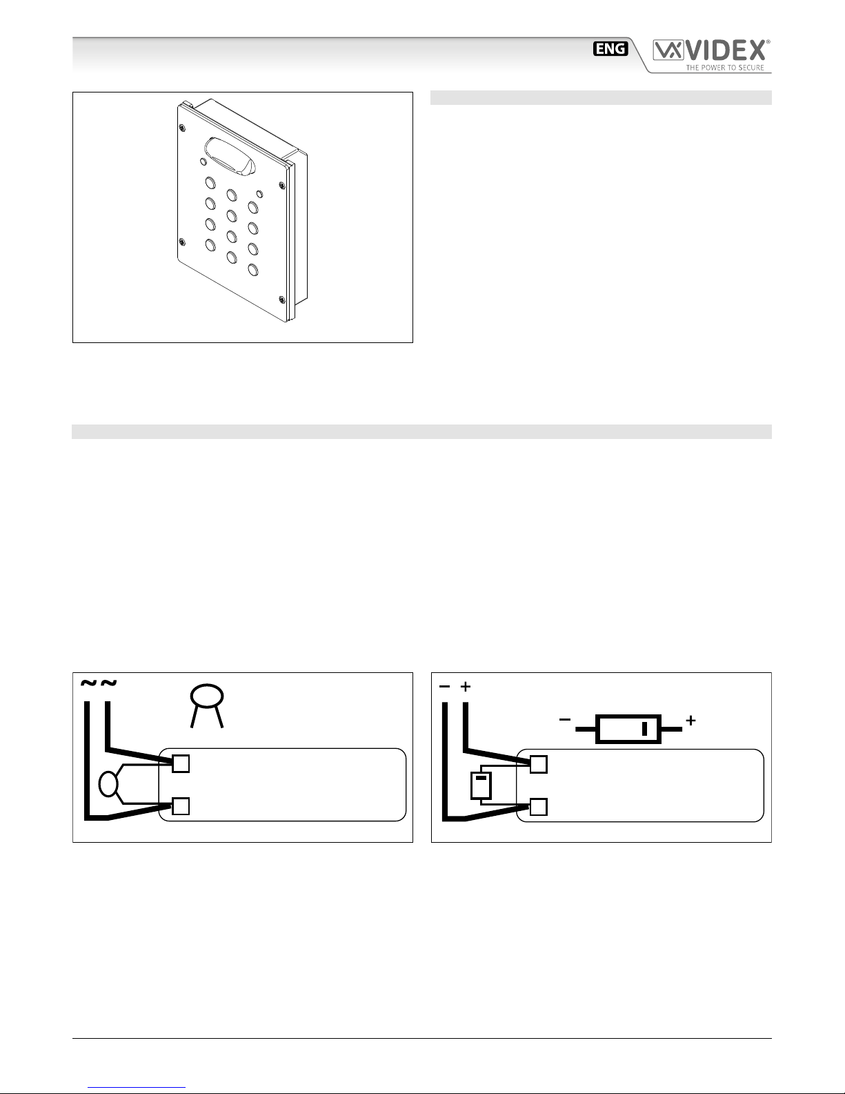
Fig. 1
DESCRIPTION
Access control system with 2 codes and 2 Relay outputs for
Art.8800 (3 codes and 3 Relay outputs for Art.8800-3).
• Engineer’s code to enter into the “Programming Menu” ( from
4 to 8 digits).
• Programming of the activation time of each relay from 1 up to
99 seconds or latching.
• Possibility to activate relay 1 by shorting terminal SW1 to GND
and relay 2 by shorting terminal SW2 to GND. Both relays will
operate for the programmed time.
• Keypad gives an acoustic (buzzer) signal during the entering
of codes and a continuous melody for 4 or more seconds, according to the number of mistakes (self protection).
• Keypad includes panel illumination and 2 LED’s to show the
following:
» Correct relay code (green LED on for 2 seconds).
» Red LED to indicate when in the “programming menu”.
AVAILABLE VERSIONS
Art.8800: Module 2 Relay with keypad illumination LEDs
Art.8800-3: Module 3 Relay with keypad illumination LEDs
GENERAL DIRECTIONS FOR INSTALLATION
In order to achieve the best results from the schematics described it is necessary to install only original VIDEX equipment, strictly
keeping to the items indicated on each schematic and follow these General Directions for Installation:
• The system must be installed according to national rules in force, in any case the running of cables of any intercom unit must be
carried out separately from the mains;
• All multipair cables should be compliant to CW1308 specication (0.5mm twisted pair telephone cable.
» Cables for speech line and service should have a max resistance of 10Ω
» Lock release wires should be doubled up (Lock release wires and power supply wires should have a max resistance of 3Ω);
• The cable sizes above can be used for distances up to 50m. On distances above 50m the cable sizes should be increased to keep
the overall resistance of the cable below the RESISTANCES indicated above;
• Double check the connections before power up;
• Power up the system then check all functions.
LOCK RELEASE BACK EMF PROTECTION
A varistor must be tted across the terminals on AC lock release
(Fig.1A)
and a diode must be tted across the terminals on a DC
lock release
(Fig.1B) to suppress back EMF voltages. Connect the components to the lock releases as shown in gures.
VARISTOR (MOV)
12V AC
LOCK RELEASE
Fig.1A
DIODE
1N4002
12V DC
LOCK RELEASE
Fig.1B
Page 2
65801280 - V2.0 - 30/06/18
- 2 -
8000 Series
Art.8800 - Installation instructions
Art.8800 - Art.8800-3 Digital codelock module
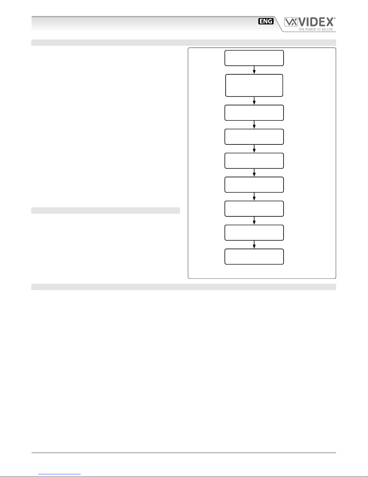
PROGRAMMING
• Enter ENGINEER’S CODE: rst time type six times 1 (111111
factory preset) and press ENTER (The red LED will illuminate).
• Conrm ENGINEER’S CODE (typing again the same) or
type the new code (4 to 8 digits) then press ENTER (Melody). Pressing twice the ENTER button without changing the
ENGINEER’S CODE, will exit from the programming.
• Enter the code (4 to 8 digits) to enable RELAY 1 (ACCESS 1) or
re-enter the existing code then press ENTER (Melody).
• Enter the RELAY 1 operation time (2 digits 01 to 99 I.E. 05=5
seconds, 00= remain open time) or re-enter the existing time
then press ENTER (Melody).
• Enter the code (4 to 8 digits) to enable RELAY 2 (ACCESS 2) or
re-enter theexisting code then press ENTER (Melody).
• Enter the RELAY 2 operation time (2 digits 01 to 99 I.E. 05=5
seconds, 00=remain open time) or re-enter the existing time
then press ENTER (Melody).
• Enter the code (4 to 8 digits) to enable RELAY 3 (ACCESS 3
only for Art.8800-3) or re-enter the existing code then press
ENTER (Melody).
• Enter the RELAY 3 (only for Art.8800-3) operation time (2 dig-
its 01 to 99 I.E. 05=5 seconds, 00=remain open time) or re-enter the existing time then press ENTER (Melody).
• The system is ready to use (the red LED will be o).
RETURN SYSTEM TO PRESET ENGINEER’S FACTORY CODE
• Turn o power to code lock;
• Keep ENTER button pressed while turning the power back on;
• Release ENTER button;
• The engineer’s code is now set to 111111 (six times one).
OPERATION
To use the system, type in the programmed code and press ENTER, the green LED will illuminate and the relay will operate for the
programmed time.To cancel remain open time, type in the same code and press CLEAR. If a wrong code is entered, a continuous
melody will sound for 4 or more seconds, according to the number of mistakes
.
OPERATION NOTES
• To operate relays together, set the same code for each relay;
• If a wrong code is entered, the system will lock out for 5 seconds which will increase each time a wrong code is entered. The system will
operate only when the correct code is enter
ENTER THE
"ENGINEER’S CODE"
CONFIRM
OR CHANGE
"ENGINEER’S CODE"
ENTER
"ACCESS 1 CODE"
ENTER
"ACCESS 2 CODE"
ENTER
"ACCESS 3 CODE"***
ENTER
"ACCESS 1 TIME"
ENTER
"ACCESS 2 TIME"
ENTER
"ACCESS 3 TIME"***
SYSTEM
READY TO USE
First time six times
1 “111111” factory
preset
Type again six times
“1” or the new engineer’s code 4 to 8
digits
Code to enable relay 1
4 to 8 digits
Code to enable relay 2
4 to 8 digits
Code to enable relay 3
4 to 8 digits
Two digits (01 to 99)
i.E. 05=5 Seconds
00= remain open
Two digits (01 to 99)
i.E. 05=5 Seconds
Two digits (01 to 99)
i.E. 05=5 Seconds
Red led will be o
Press Enter
(Red LED will
be ON)
Press Enter
(melody)
Press Enter
(melody)
Press Enter
(melody)
Press Enter
(melody)
Press Enter
(melody)
Press Enter
(melody)
Press Enter
(melody)
*** Only for Art.8800-3
Page 3
65801280 - V2.0 - 30/06/18
- 3 -
8000 Series
Art.8800 - Installation instructions
Art.8800 - Art.8800-3 Digital codelock module
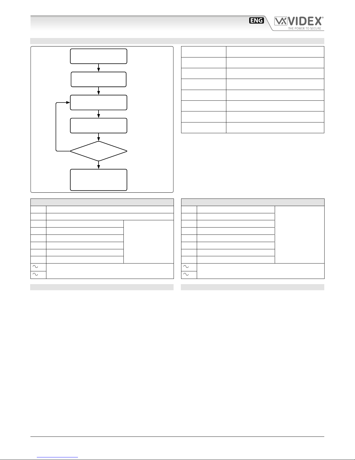
REPROGRMMING GUIDE
ENTER THE
ENGINEER’S CODE
REENTER THE
ENGINEER’S CODE
ENTER
ACCESS CODE
ENTER
ACCESS TIME
PRESS ENTER
TWICE TO EXIT
PROGRAMMING
MORE
DOORS?
Alternatively enter a
new engineer’s code
(4 to 8 digits)
Press Enter
(Red light will illuminate*)
Press Enter
Press Enter
Press Enter
Repeat steps for relay 2
and relay 3
***
YES
NO
Relay code (4-8 digits) operate the door
or gate.**
Two digits (01-99
sec or 00 for remain
open)
Engineer’s code
Relay 1 code
Relay 2 code
Relay 3 code***
Relay 1 time
Relay 2 time
Relay 3 time***
Notes:
* If the red light does not illuminate, the engineer’s code is
incorrect. Follow instructions to return system to preset engineer’s factory code.
** On the rst loop of the ow chart its relay 1, second loop is
relay 2 and third loop is relay 3.
*** Only for Art.8800-3
ART.8800 CONNECTION TERMINALS SIGNALS
SW1 Relay 1 command signal (active low)
SW2 Relay 2 command signal (active low)
NC2 Relay 2 normally closed contact
Max
24Vac/dc
5A
NO2 Relay 2 normally open contact
C2 Relay 2 common contact
NC1 Relay 1 normally closed contact
NO1 Relay 1 normally open contact
C1 Relay 1 common contact
/
+
12/24Vac/dc power input
/
–
ART.88003 CONNECTION TERMINALS SIGNALS
NO3 Relay 3 normally open contact
Max
24Vac/dc
5A
C3 Relay 3 common contact
NC2 Relay 2 normally closed contact
NO2 Relay 2 normally open contact
C2 Relay 2 common contact
NC1 Relay 1 normally closed contact
NO1 Relay 1 normally open contact
C1 Relay 1 common contact
/
+
12/24Vac/dc power input
/
–
TECHNICAL SPECIFICATIONS
Power requirements: 12/24V AC/DC, 2VA
Power Consumption: On AC On DC
Stand-by: 82mA 21.5mA
Operating: 125mA 35.0mA
Working Temperature: -10 +50° C
CLEANING OF THE PLATE
Use a clean and soft cloth. Use moderate warm water or non-aggressive cleansers.
Do not use:
• abrasive liquids;
• chlorine-based liquids;
• metal cleaning products.
Page 4
65801280 - V2.0 - 30/06/18
- 4 -
Serie 8000
Art.8800 - 8800-3 - Istruzioni di installazione
Art.8800 - Art.8800-3 Tastiera digitale
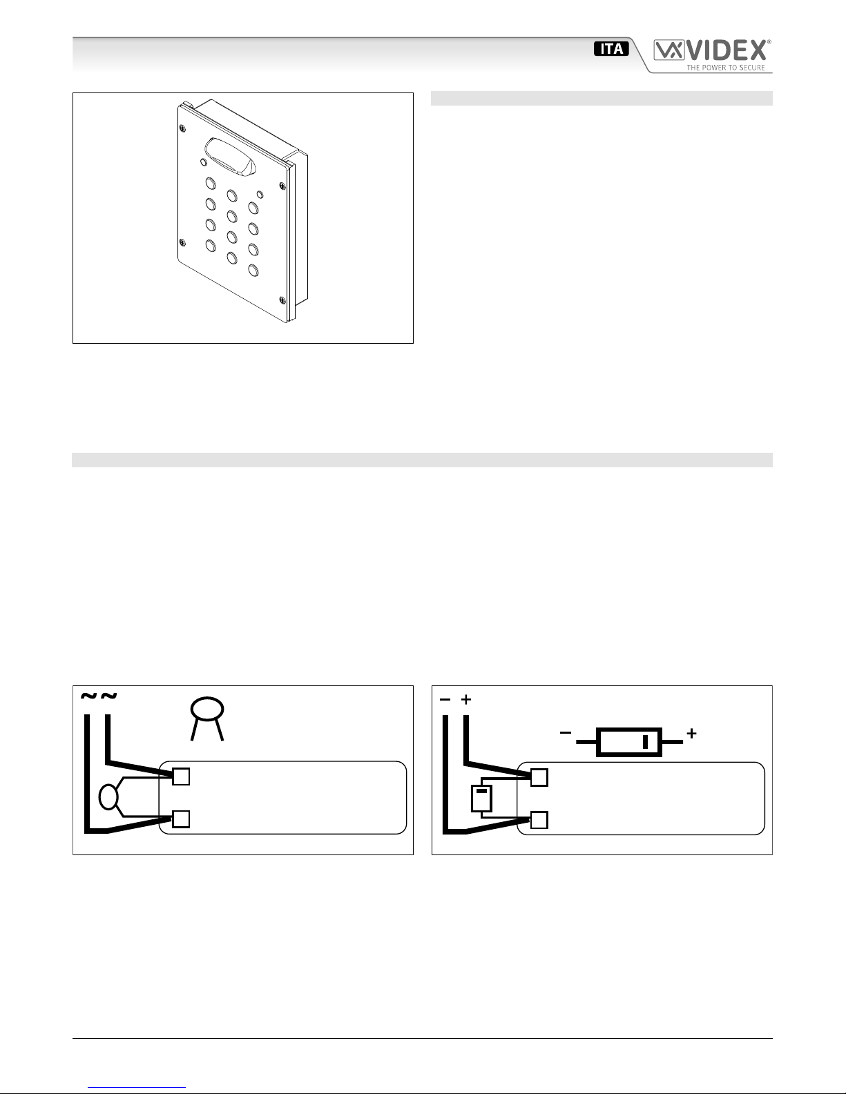
Fig. 1
DESCRIZIONE
Sistema di controllo accessi con 2 codici e 2 uscite relè per
l’Art.8800 (3 codici e 3 uscite relè per l’ Art.8800-3).
• Codice di accesso al menù di programmazione congurabile
(da 4 ad 8 cifre).
• Impostazione di ciascun relè per l’attivazione temporizzata
(da 1 a 99 secondi) o la commutazione (00 nella programmazione del tempo relè).
• Possibilità di attivare i Relè 1 e 2 collegando a massa rispettivamente i morsetti SW1 ed SW2. I relè funzioneranno per il
tempo programmato.
• La tastiera emette dei segnali acustici durante l’utilizzo ed è
dotata di autoprotezione in caso di inserimento di codici errati (segnale acustico della durata di 4 o più secondi).
• La tastiera è dotata di illuminazione e di due LED per indicare
quanto segue:
» Inserimento di un codice corretto (LED verde acceso per
2 secondi).
» Menù di programmazione attivo (LED rosso acceso).
VERSIONI DISPONIBILI
Art.8800: Modulo a 2 Relè con illuminazione tastiera
Art.8800-3: Modulo a 3 Relè con illuminazione tastiera
NORME GENERALI D’INSTALLAZIONE
Per eseguire una corretta installazione è necessario impiegare esclusivamente parti VIDEX, seguire con scrupolo quanto indicato
negli schemi di collegamento e tenere presenti le norme generali d’installazione:
• Realizzare gli impianti secondo le vigenti normative nazionali ed in ogni caso si
• consiglia di prevedere, per i conduttori dell’impianto, una canalizzazione distinta da quella della linea elettrica (vedi paragrafo
seguente per il collegamento alla linea elettrica e l’installazione dell’alimentatore);
• Impiegare conduttori con sezioni tali da avere:
» Resistenza complessiva inferiore a 10Ω per quelli della linea fonica e di comando;
» Lresistenza complessiva inferiore a 3Ω per quelli della serratura e di alimentazione;
• Vericare le connessioni prima di dare alimentazione all’impianto;
• Alimentare l’impianto ed eseguire il collaudo vericandone tutte le funzioni.
AZIONAMENTO SERRATURA PROTEZIONE DAI DISTURBI
L’azionamento della serratura elettrica può provocare degli spike, per evitare tale inconveniente si consiglia di collegare tra i terminali della serratura un varistore
(Fig.1A) o un diodo (Fig.1B) a seconda che la serratura sia in alternata o in continua.
VARISTOR (MOV)
12V AC
LOCK RELEASE
Fig.1A
DIODE
1N4002
12V DC
LOCK RELEASE
Fig.1B
Page 5

65801280 - V2.0 - 30/06/18
- 5 -
Serie 8000
Art.8800 - 8800-3 - Istruzioni di installazione
Art.8800 - Art.8800-3 Tastiera digitale
PROGRAMMAZIONE
• Digitare il MASTER CODE: 6 volte 1 (111111 impostazione di
fabbrica) e premere ENTER (il LED rosso si accende).
• Confermare il MASTER CODE (digitandolo nuovamente) o digitarne uno nuovo (da 4 ad 8 cifre) quindi premere ENTER (segnale acustico). Premendo due volte ENTER senza modicare
il MASTER CODE si esce dalla programmazione.
• Digitare il codice di attivazione (da 4 ad 8 cifre) del RELÉ 1
quindi premere ENTER (segnale acustico).
• Digitare il tempo di funzionamento del RELÉ 1 (2 cifre da 01 a
99 Es. 05=5 secondi 00=Commutazione di stato) quindi premere ENTER (segnale acustico).
• Digitare il codice di attivazione (da 4 ad 8 cifre) del RELÉ 2
quindi premere ENTER (segnale acustico).
• Digitare il tempo di funzionamento del RELÉ 2 quindi premere ENTER (segnale acustico).
• Digitare il codice di attivazione (da 4 ad 8 cifre) del RELÉ 3
quindi premere ENTER (segnale acustico).
• Digitare il tempo di funzionamento del RELÉ 3 quindi premere ENTER (segnale acustico).
• Il sistema è pronto all’uso (il LED rosso si spegne).
RIPORTARE L’UNITÀ ALLE IMPOSTAZIONI DI FABBRICA
• Togliere l’alimentazione alla tastiera;
• Tenendo premuto il tasto ENTER, dare nuovamente alimentazione;
• Rilasciare il tasto ENTER;
• Il codice master è nuovamente impostato a 111111 (sei volte
uno).
FUNZIONAMENTO
Per utilizzare il sistema, digitale il codice e premere ENTER, il LED verde si accende ed il relè funzionerà per il tempo programmato.
Per disattivare un relè (impostato per l’attivazione temporizzata o a commutazione di stato), digitare lo stesso codice e premere
CLEAR. Se viene digitato un codice errato, la tastiera emettere un segnale acustico continuo della durata di 4 o più secondi in base
al numero di errori.
NOTE DI FUNZIONAMENTO
• Per far funzionare i relé contemporaneamente, impostare lo stesso codice d’attivazione per ciascun relé.
• Se viene digitato un codice errato, l’unità si blocca per 5 secondi: il tempo di blocco aumenta in base al numero di errati inserimenti. L’unità funzionerà solo digitando un codice corretto.
DIGITARE IL
“MASTER CODE”
CONFERMARE
O CAMBIARE IL
“MASTER CODE”
DIGITARE IL
CODICE RELÈ 1
DIGITARE IL
CODICE RELÈ 2
DIGITARE IL
CODICE RELÈ 3***
DIGITARE IL
TEMPO RELÈ 1
DIGITARE IL
TEMPO RELÈ 2
DIGITARE IL
TEMPO RELÈ 3***
IL SISTEMA È
PRONTO ALL’USO
6 Volte 1 “111111”
impostazione di fabbrica
Digitare nuovamente
6 volte 1o un nuovo
codice da 4 a 8 cifre
Codice di attivazione
relè 1, da 4 a 8 cifre
Codice di attivazione
relè 2, da 4 a 8 cifre
Codice di attivazione
relè 3, da 4 a 8 cifre
Due cifre (da 01 a 99)
es. 05=5 Secondi
00= Comm. Di stato
Due cifre (da 01 a 99)
es. 05=5 Secondi
Due cifre (da 01 a 99)
es. 05=5 Secondi
Il led rosso si spegne
Premere Enter
(Il LED rosso si
accende)
Premere Enter
(Segnale acustico)
Premere Enter
(Segnale acustico)
Premere Enter
(Segnale acustico)
Premere Enter
(Segnale acustico)
Premere Enter
(Segnale acustico)
Premere Enter
(Segnale acustico)
Premere Enter
(Segnale acustico)
*** Solo per l’Art.8800-3
Page 6

65801280 - V2.0 - 30/06/18
- 6 -
Serie 8000
Art.8800 - 8800-3 - Istruzioni di installazione
Art.8800 - Art.8800-3 Tastiera digitale
GUIDA ALLA RIPROGRAMMAZIONE
DIGITARE IL CODICE
INSTALLATORE
DIGITARE DI NUOVO
IL CODICE
DIGITARE IL CODICE
DI ACCESSO
DIGITARE IL TEMPO
DI ATTIVAZIONE RELÈ
PREMERE 2 VOLTE
ENTER PER USCIRE
ALTRI
RELÈ?
In alternativa inserire un nuovo Master
code (da 4 a 8 cifre)
Premere Enter
(il LED rosso si accende*)
Premere Enter
Premere
Enter
Premere
Enter
Ripetere le stesse operazioni per il relé 2
e relé 3
***
SI
NO
Il codice relé (4-8 cifre) attiva la porta o
il cancello**
Due cifre (01-99 sec
o 00 per rimanere
aperto)
Codice installatore
Codice relé 1
Codice relé 2
Codice relé 3***
Tempo relé 1
Tempo relé 2
Tempo relé 3***
Note
* Se il LED rosso non si accende, il codice installatore non è
corretto. Seguire le istruzioni per ripristinare il codice installatore di fabbrica.
** Al primo passaggio del ow chart si sta operando sul relé 1, al
secondo passaggio sul relé 3 e al terzo passaggio sul relé 3.
*** Solo per l’Art.8800-3
SEGNALI MORSETTERIA DI CONNESSIONE ART.8800
SW1 Comando d’abilitazione del relé 1 (ingresso attivo basso)
SW2 Comando d’abilitazione del relé 2 (ingresso attivo basso)
NC2 Relé 2 contatto normalmente chiuso
Max
24Vac/dc
5A
NO2 Relé 2 contatto normalmente aperto
C2 Relé 2 contatto comune
NC1 Relé 1 contatto normalmente chiuso
NO1 Relé 1 contatto normalmente aperto
C1 Relé 1 contatto comune
/
+
Ingresso d’alimentazione 12/24Vac/dc
/
–
SEGNALI MORSETTERIA DI CONNESSIONE ART.88003
NO3 Relé 3 contatto normalmente aperto
Max
24Vac/dc
5A
C3 Relé 3 contatto comune
NC2 Relé 2 contatto normalmente chiuso
NO2 Relé 2 contatto normalmente aperto
C2 Relé 2 contatto comune
NC1 Relé 1 contatto normalmente chiuso
NO1 Relé 1 contatto normalmente aperto
C1 Relé 1 contatto comune
/
+
Ingresso d’alimentazione 12/24Vac/dc
/
–
SPECIFICHE TECNICHE
Tensione d’alimentazione: 12/24V AC/DC, 2VA
Assorbimento: Con AC Con DC
A riposo: 82mA 21.5mA
In funzione: 125mA 35.0mA
Working Temperature: -10 +50° C
PULIZIA DELLA PLACCA
Usare un panno morbido e pulito. Usare acqua tiepida o un detergente non aggressivo.
Non usare:
• prodotti abrasivi;
• prodotti contenenti cloro;
• prodotti per la pulizia dei metalli.
Page 7

65801280 - V2.0 - 30/06/18
- 7 -
Série 8000
Art.8800 - 8800-3 - Manuel d'installation
Art.8800 - Art.8800-3 Clavier numérique
Fig. 1
DESCRIPTION
Système de contrôle, accès avec 2 codes et 2 sorties relais pour
l’Art. 8800 (3 codes et 3 sorties relais pour l’Art. 8800-3).
• Code d’accès au menu de programmation congurable (de 4
à 8 chires).
• Conguration de chaque relais pour l’activation temporisée
(de 1 à 99 secondes) ou la commutation (00 dans la programmation du temps relais)
• Possibilité d’activer les Relais 1 et 2 en raccordant à la masse
respectivement les bornes
SW1 et SW2. Les relais fonctionne-
ront pendant le temps programmé.
•
Le clavier émet des signaux acoustiques durant l’utilisation et
il est doté d’auto-protection en cas de saisie de codes erronés
(signal acoustique de la durée de 4 ou plusieurs secondes).
• Le clavier est doté d’un éclairage et de deux LED pour indiquer
ce qui suit:
» Saisie d’un code correct (LED verte allumée pendant 2 se-
condes).
» Menu de programmation activé (LED rouge allumée).
VERSIONS DISPONIBLES
Art.8800 : Module à 2 Relais avec éclairage clavier
Art.8800-3 : Module à 3 Relais avec éclairage clavier
NORMES GÉNÉRALES D’INSTALLATION
Pour eectuer une installation correcte il faut utiliser exclusivement des pièces VIDEX, suivre attentivement ce qui est indiqué sur
les schémas de raccordement et respecter les normes générales d’installation :
• Réaliser les installations conformément aux réglementations en vigueur nationales et dans tous les cas il est
• conseillé de prévoir, pour les gestionnaires de l’installation, une canalisation distincte de celle de la ligne électrique (voir le paragraphe suivant pour le raccordement à la ligne électrique et l’installation de l’alimentateur);
• Utiliser des conducteurs avec des sections telles à avoir :
» Résistance totale inférieure à 10Ω pour ceux de la ligne phonique et de commande ;
» Résistance totale inférieure à 3Ω pour ceux de la serrure et d’alimentation ;
• Vérier les connexions avant d’activer l’alimentation à l’installation ;
• Alimenter l’installation et eectuer le contrôle en en vériant toutes les fonctions.
ACTIONNEMENT DE LA SERRURE PROTECTION CONTRE LES DERANGEMENTS
L’actionnement de la serrure électrique peut provoquer des pics, pour eviter cet inconvénient, il est recommandé de connecter un
varistor
(Fig.1A) ou un diode (Fig.1B) entre les bornes de la serrure électrique selon le type de alimentation (directe ou alternée).
VARISTOR (MOV)
12V AC
LOCK RELEASE
Fig.1A
DIODE
1N4002
12V DC
LOCK RELEASE
Fig.1B
Page 8

65801280 - V2.0 - 30/06/18
- 8 -
Série 8000
Art.8800 - 8800-3 - Manuel d'installation
Art.8800 - Art.8800-3 Clavier numérique
PROGRAMMATION
• Saisir le
MASTER CODE : 6 fois 1 (111111 conguration
d'usine) et appuyer sur
ENTER (la LED rouge s'allume).
• Conrmer le
MASTER CODE (en saisissant de nouveau) ou en
saisir un nouveau (de 4 à 8 chires) et appuyer sur
ENTER (si-
gnal acoustique). En appuyant deux fois sur
ENTER sans modi-
er le
MASTER CODE on sort de la programmation.
• Saisir le code d'activation (de 4 à 8 chires) du
RELAIS 1 et ap-
puyer sur
ENTER (signal acoustique).
• Saisir le temps de fonctionnement du
RELAIS 1 (2 chires de
01 à 99
Ex. 05=5 secondes 00=Commutation d'état) et appuyer
sur
ENTER (signal acoustique).
• Saisir le code d'activation (de 4 à 8 chires) du
RELAIS 2 et ap-
puyer sur
ENTER (signal acoustique).
• Saisir le temps de fonctionnement du
RELAIS 2 et appuyer sur
ENTER (signal acoustique).
• Saisir le code d'activation (de 4 à 8 chires) du
RELAIS 3 et ap-
puyer sur
ENTER (signal acoustique).
• Saisir le temps de fonctionnement du
RELAIS 3 et appuyer sur
ENTER (signal acoustique).
• Le système est prêt à l'usage (la LED rouge s'éteint).
REMETTRE L’UNITÉ AUX CONFIGURATIONS D’USINE
• Couper l’alimentation au clavier ;
• En tenant appuyée la touche ENTER, activer de nouveau l’alimentation ;
• Relâcher la touche ENTER ;
• Le code master est de nouveau conguré à 111111 (six fois un).
FONCTIONNEMENT
Pour utiliser le système, saisir le code et appuyer sur ENTER, la LED verte s’allume et le relais fonctionnera pendant le temps programmé. Pour
désactiver un relais (conguré par l’activation temporisée ou à commutation d’état), saisir le même code et appuyer sur
CLEAR. Si un code
erroné est saisi, le clavier émet un signal acoustique continu qui dure 4 ou plusieurs secondes en fonction du nombre d’erreurs.
NOTES DE FONCTIONNEMENT
• Pour faire fonctionner les relais simultanément, congurer le même code d’activation pour chaque relais.
• Si un code erroné est saisi, l’unité se bloque pendant 5 secondes : le temps de blocage augmente en fonction du nombre de saisies erronées. L’unité fonctionnera uniquement en saisissant un code correct.
SAISIR LE MASTER
CODE:
CONFIRMER OU
CHANGER LE
MASTER CODE
SAISIR LE
CODE RELAIS 1
SAISIR LE
CODE RELAIS 2
SAISIR LE
CODE RELAIS 3***
SAISIR LE
TEMPS RELAIS 1
SAISIR LE
TEMPS RELAIS 2
SAISIR LE
TEMPS RELAIS 3***
LE SYSTÈME EST
PRÊT À L'USAGE
6 Fois 1 « 111111 »
conguration d'usine
Saisir de nouveau 6
fois 1 ou un nouveau
code de 4 à 8 chires
Code d'activation relais 1, de 4 à 8 chires
Code d'activation relais 2, de 4 à 8 chires
Code d'activation relais 3, de 4 à 8 chires
Deux chires (de 01
à 99) ex. 05=5 Secondes 00= Comm.
D'état
Deux chires (de 01
à 99) ex. 05=5 Secondes
Deux chires (de 01
à 99) ex. 05=5 Secondes
La LED rouge
s'éteint
Appuyer sur
Enter (La LED
rouge s'allume)
Appuyer sur
Enter (Signal
acoustique)
Appuyer sur
Enter (Signal
acoustique)
Appuyer sur
Enter (Signal
acoustique)
Appuyer sur
Enter (Signal
acoustique)
Appuyer sur
Enter (Signal
acoustique)
Appuyer sur
Enter (Signal
acoustique)
Appuyer sur
Enter (Signal
acoustique)
*** Uniquement pour l’Art.8800-3
Page 9

65801280 - V2.0 - 30/06/18
- 9 -
Série 8000
Art.8800 - 8800-3 - Manuel d'installation
Art.8800 - Art.8800-3 Clavier numérique
GUIDE À LA REPROGRAMMATION
SAISIR LE CODE
INSTALLATEUR
SAISIR LE NOUVEAU
CODE
SAISIR LE CODE
D'ACCÈS
SAISIR LE TEMPS
D'ACTIVATION RELAIS
APPUYER 2 FOIS SUR
ENTER POUR SORTIR
AUTRES RELAIS
?
Comme alternative
saisir un nouveau
Master code (de 4 à
8 chires)
Appuyer sur Enter
(la LED rouge s'allume*)
Appuyer sur Enter
Appuyer
sur Enter
Appuyer
sur Enter
Répéter les mêmes
opérations pour le relais 2*
et le relais 3
***
OUI
NO
Le code relais (4-8
chires) active la
porte ou le portail**
Deux chires (0199 secondes ou 00
pour rester ouvert)
Code installateur
Code relais 1
Code relais 2
Code relais 3***
Temps relais 1
Temps relais 2
Temps relais 3***
Note
* Si la LED rouge ne s’allume pas, le code installateur est in-
correct. Suivre les instructions pour rétablir le code installateur d’usine.
** Au premier passage du ow chart l’on opère sur le relais 1,
au deuxième passage sur le relais 3 et au troisième passage
sur le relais 3.
*** Uniquement pour l’Art.8800-3
BORNIER ART.8800
SW1 Commande d'activation du relais 1 (entrée activée faible)
SW2 Commande d'activation du relais 2 (entrée activée faible)
NC2 Relais 2 contact normalement fermé
Max
24Vac/dc
5A
NO2 Relais 2 contact normalement ouvert
C2 Relais 2 contact commun
NC1 Relais 1 contact normalement fermé
NO1 Relais 1 contact normalement ouvert
C1 Relais 1 contact commun
/
+
Entrée d'alimentation 12/24Vac/dc
/
–
BORNIER ART.88003
NO3 Relais 3 contact normalement ouvert
Max
24Vac/dc
5A
C3 Relais 3 contact commun
NC2 Relais 2 contact normalement fermé
NO2 Relais 2 contact normalement ouvert
C2 Relais 2 contact commun
NC1 Relais 1 contact normalement fermé
NO1 Relais 1 contact normalement ouvert
C1 Relais 1 contact commun
/
+
Entrée d'alimentation 12/24Vac/dc
/
–
CARACTÉRISTIQUES TECHNIQUES :
Tension d'alimentation : 12/24V AC/DC, 2VA
Absorption : Avec AC Avec DC
Au repos : 82mA 21.5mA
En fonction : 125mA 35.0mA
Working Temperature : -10 +50°C
NETTOYAGE DE LA PLATINE
Utilisez un chion propre et doux. Utiliser de l’eau tiède ou des
nettoyants non agressifs.
Ne pas utiliser :
• liquids abrasifs ;
• liquids avec chlore ;
• nettoyants pour surfaces metalliques.
Page 10

65801280 - V2.0 - 30/06/18
- 10 -
12Vdc
1N4002
FAIL SAFE DC LOCK
ART.521
230V
0
+
PUSH TO EXIT
FAIL SAFE LOCK RELEASE
12Vac
FAIL SECURE AC LOCK
PUSH TO EXIT
FAIL SECURE LOCK RELEASE
100uF
13V
ART.321
230V
12Vdc P.S.U.
12Vac P.S.U.
ELECTRIC GATES
PUSH TO EXIT
13V
ART.321
230V
12-24Vac/dc Input
VOLT FREE CONTACTS
VX8800
+
-
C1
NC1NO1 NO2C2NC2 SW1
SW2
12¸ 24
Vac/dc
VX8800
+
-
C1
NC1NO1 NO2C2NC2 SW1
SW2
12¸ 24
Vac/dc
VX8800
+
-
C1
NC1NO1 NO2C2NC2 SW1
SW2
12¸ 24
Vac/dc
VX8800-2.dwg
Page 11

65801280 - V2.0 - 30/06/18
- 11 -
ART.520M
230V
0
+12 +
12V
SE
AC
YELLOW
4
VOL.REG.
6 2
BLACK
GREEN
31 518 9
Art.3111
RED
23 41 2
P
+
2
-
1
1S S C
Art.8837M-2..
P2 1 1 C
4n..................4
Art.8845..
3 C
VX8800-8837M.dwg
SW1
VX8800
NC1
+
-
NO1
C1 C2
NO2 SW2NC2
12¸ 24
Vac/dc
Page 12

65801280 - V2.0 - 30/06/18
- 12 -
2
1
3 2 1 5
SE
Art.8837-2
2
3
1
4 X P P C
12
12V
Art.924
4 6 2
BLUE
RED
WHITE
31 5 9 8
Art.924
4 6 2
BLUE
RED
WHITE
31 5 9 8
6n..................6
Art.8845..
3 C
SW1
VX8800
NC1
+
-
NO1
C1 C2
NO2 SW2NC2
ART.520M
0
230V
++12
or 520
12¸ 24
Vac/dc
VX8800-8837.dwg
Page 13

65801280 - V2.0 - 30/06/18
- 13 -
ART.520M
230V
0
+12 +
12V
SE
AC
YELLOW
4
VOL.REG.
6 2
BLACK
GREEN
31 518 9
Art.3111
RED
23 41 2
P
+
2
-
1
1S S C
Art.8837M-2..
P2 1 1 C
4n..................4
Art.8845..
3 C
VX8800-8837M.dwg
SW1
VX8800
NC1
+
-
NO1
C1 C2
NO2 SW2NC2
12¸ 24
Vac/dc
Page 14

65801280 - V2.0 - 30/06/18
- 14 -
SE
0
ART.522
230V
FUSE
12V
Door Open Button
Lamp Button
ART.321
LAMP
24Vac/dc 5A max
POWER
VX8800
+
-
C1
NC1NO1 NO2
C2
NC2 SW1
SW2
12¸ 24
Vac/dc
VX8800.dwg
Page 15

65801280 - V2.0 - 30/06/18
- 15 -
Page 16

MANUFACTURER
FABBRICANTE
FABRICANT
FABRICANTE
FABRIKANT
VIDEX ELECTRONICS S.P.A.
Via del Lavoro, 1
63846 Monte Giberto (FM) Italy
Tel (+39) 0734 631669
Fax (+39) 0734 632475
www.videx.it - info@videx.it
CUSTOMER SUPPORT
SUPPORTO CLIENTI
SUPPORTS CLIENTS
ATENCIÓN AL CLIENTE
KLANTENDIENST
VIDEX ELECTRONICS S.P.A.
www.videx.it - technical@videx.it
Tel: +39 0734-631669
Fax: +39 0734-632475
UK Customers only:
VIDEX SECURITY LTD
www.videxuk.com
Tech Line: 0191 224 3174
Fax: 0191 224 1559
Main UK oce:
VIDEX SECURITY LTD
1 Osprey Trinity Park
Trinity Way
LONDON E4 8TD
Phone: (+44) 0870 300 1240
Fax: (+44) 020 8523 5825
www.videxuk.com
marketing@videxuk.com
Northern UK oce:
VIDEX SECURITY LTD
Unit 4-7
Chillingham Industrial Estate
Chapman Street
NEWCASTLE UPON TYNE - NE6 2XX
Tech Line: (+44) 0191 224 3174
Phone: (+44) 0870 300 1240
Fax: (+44) 0191 224 1559
Greece oce:
VIDEX HELLAS Electronics
48 Filolaou Str.
11633 ATHENS
Phone: (+30) 210 7521028
(+30) 210 7521998
Fax: (+30) 210 7560712
www.videx.gr
videx@videx.gr
Danish oce:
VIDEX DANMARK
Hammershusgade 15
DK-2100 COPENHAGEN
Phone: (+45) 39 29 80 00
Fax: (+45) 39 27 77 75
www.videx.dk
videx@videx.dk
Benelux oce:
NESTOR COMPANY NV
E3 laan, 93
B-9800 Deinze
Phone: (+32) 9 380 40 20
Fax: (+32) 9 380 40 25
www.videx.be
info@videx.be
Dutch oce:
NESTOR COMPANY BV
Business Center Twente (BCT )
Grotestraat, 64
NL-7622 GM Borne
www.videxintercom.nl
info@videxintercom.nl
El producto lleva la marca CE que demuestra su conformidad y puede ser
distribuido en todos los estados miembros de la unión europea UE.
Este producto cumple con las Directivas Europeas 2014/30/EU (EMC);
2014/35/EU (LVD); 2011/65/EU (RoHS): marca CE 93/68/EEC.
Het product heeft de CE-markering om de conformiteit ervan aan te tonen en
is bestemd voor distributie binnen de lidstaten van de EU zonder beperkin-
gen. Dit product volgt de bepalingen van de Europese Richtlijnen 2014/30/EU
(EMC); 2014/35/EU (LVD); 2011/65/EU (RoHS): CE-markering 93/68/EEG.
Le produit est marqué CE à preuve de sa conformité et peut être distribué
librement à l’intérieur des pays membres de l’union européenne EU.
Ce produit est conforme aux directives européennes 2014/30/EU (EMC) ;
2014/35/EU (LVD) ; 2011/65/EU (RoHS): marquage CE 93/68/EEC.
The product is CE marked demonstrating its conformity and is for distribution
within all member states of the EU with no restrictions. This product follows
the provisions of the European Directives 2014/30/EU (EMC); 2014/35/EU
(LVD); 2011/65/EU (RoHS): CE marking 93/68/EEC.
Il prodotto è marchiato CE a dimostrazione della sua conformità e può essere
distribuito liberamente all’interno dei paesi membri dell’Unione Europea UE.
Questo prodotto è conforme alle direttive Europee: 2014/30/UE (EMC);
2014/35/UE (LVD); 2011/65/UE (RoHS): marcatura CE 93/68/EEC.
 Loading...