

Page 1
66251550-EN - V1.0 - 15/02/17
1
6700 Series
Art.6758 - Installation instructions
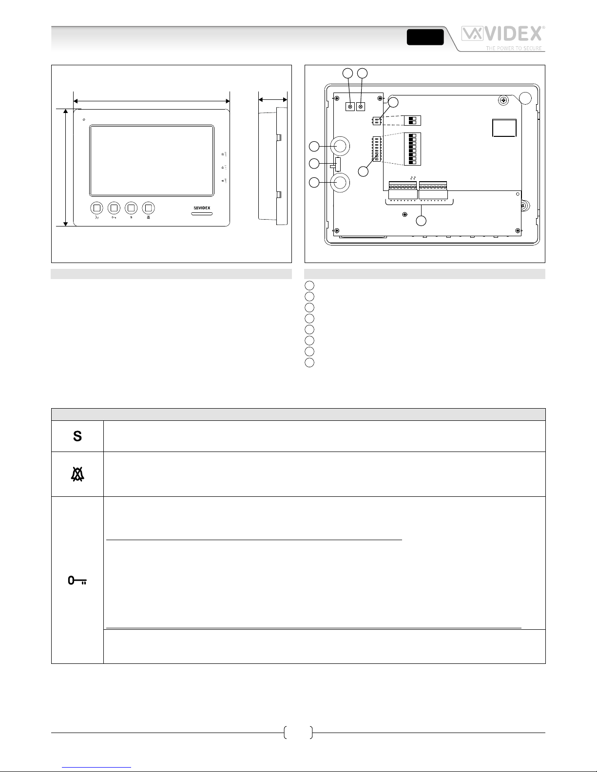
Art.6758 7" hands free colour display digital videomonitor
27mm
200mm
150mm
Fig. 1
PT2 PT3
PT1
SW1
VR1
6 7 8
1
2
3
5
4
ON
DSW1
DSW2
1
2
ON
V2V121−
+V
4A
5A
12M
3A2ALDSBLB
A
B
C
H
G
F
D E
Fig. 2
DESCRIPTION
Surface mount hands free videophone incorporating a 7” Hi-Res
full colour active matrix LCD monitor specic for “6 wire” videokit (VK4K, VRVK and VK8K range). It includes 4 buttons: “camera recall” “open door ” “service” and “privacy”.
3 LED’s* indicate the privacy activated , open door and activated functions.
Programmable privacy duration and number of rings. Intercommunicating call and door call.
Adjustments: call tone volume switch (3 levels), picture hue,
contrast and brightness.
* The operation of some LED’s and the functions described may require additional cabling.
LEGEND
A
Connection terminals
B
8 Way dip switch bank to set videophone address
C
2 Way dip switch bank to set video mode
D
Hue adjustment trimmer
E
Contrast adjustment trimmer*
F
Speech volume control
G
Brightness control
H
Call tone volume switch
* Not available in some LCD versions.
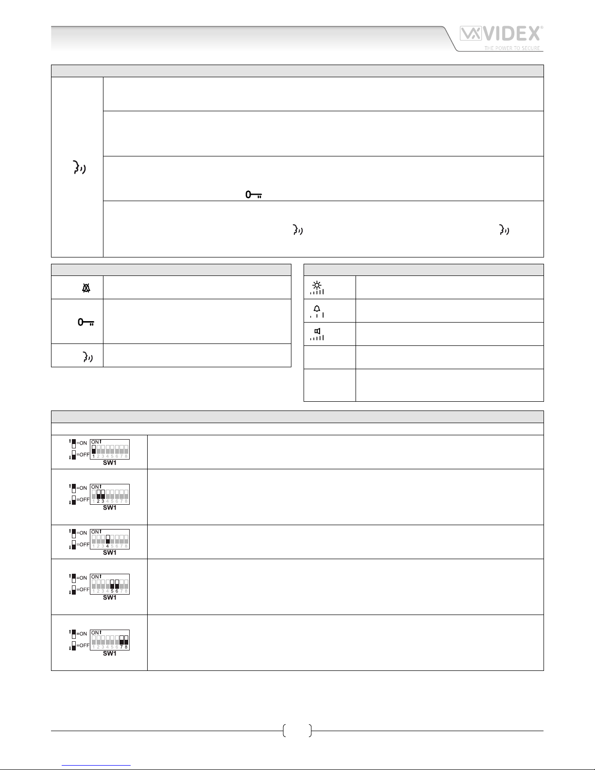
PUSH BUTTONS FIG. 1
Service push button.
Shorts the “SB” terminal to GROUND (open collector 24Vdc 100mA max) while the button remain pressed.
Privacy ON-OFF button.
When the system is in stand-by, the pressing of this button activates (LED switched on) or disables (LED switched
o) the “privacy” service. The service is automatically disabled when the programmed privacy time expires. When
the service is enabled the videophone does not receive calls.
Door-open / intercommunicating call button.
With speech lines open to the entrance panel, press this button to open the door. If the terminal “LD” is properly
connected the relevant LED remains switched ON until the door is closed.
Intercommunication only works when the system is in the stand-by condition.
Switch 4 of the SW1 dip-switch selects the type of intercommunication:
OFF Intercommunication between two apartments - press the key button to call the videophone(s) in the other
apartment. A busy tone will signal that the other videophone is in conversation with the door station and so
cannot be called.
ON Intercommunication between videophones in the same apartment
- press the key button one, two, three or four times to call videophone with extension address 1, 2, 3 or 4 (Set on
dip-switches 2&3 of SW1).
Any intercommunicating conversation is always interrupted by an external call (i.e. External calls take priority).
Intercommunication push button.
For an intercommunicating call, press as many times as the extension or address value to call (see SW3 Intercommunication Settings).
ENG
Page 2
66251550-EN - V1.0 - 15/02/17
2
6700 Series
Art.6758 - Installation instructions
Art.6758 7" hands free colour display digital videomonitor
PUSH BUTTONS FIG. 1
Answer push button.
On an incoming call, pressing this button allows the user to answer and converse with the visitor. The relevant LED
will illuminate.
Switch o button.
With the system switched on (monitor on), momentary operation of the button will switch the video monitor o.
The videomonitor will also automatically switch o after a time delay if the button is not pressed. The relevant LED
will switch o.
Camera recall button.
Press the button (Press once for door/gate 1, twice for 2 and so on up to a maximum of 4 entrances): the relevant
LED switches ON and the monitor switches on showing the video from the door panel. The speech is also live and
the door can be opened by pressing
.
Simplex button.
Pressing and holding the button for more than 3 seconds will switch the videomonitor into SIMPLEX speech mode.
Press and hold the button to speak to the caller (
LED will ash rapidly), release the button to listen ( LED will
ash slowly). If the button is not pressed for 10 seconds the videomonitor will switch o. The videomonitor will revert to duplex speech when another call is made.
LEDS FIG. 1
LED
Privacy on LED
It illuminates when the privacy service is enabled.
LED
Generic use LED
It is controlled from the terminals “+DOL” and
“-DOL”. Normally used to signal the door status
(open or closed).
LED
ON LED
It illuminates when the videophone is switched ON.
CONTROLS AND ADJUSTMENTS FIG. 1 AND FIG. 2
PT1
Brightness control
(Sliding wheel).
SW1
Speech volume control
(3 levels switch).
VR1
Call tone volume control
(Sliding wheel).
PT2
Hue adjustment trimmer
(Rotate left to increase or right to decrease).
PT3
Contrast adjustment trimmer*
(Rotate left to increase or right to decrease).
* Not available in some LCD versions.
SETTINGS DIPSWITCH
The videophone setup is carried out by the 2 dip-switch banks.
Switch 1 Apartment Address
OFF 1
ON 2
Switches 2,3 Extension Address
OFF OFF 1
ON OFF 2
OFF ON 3
ON ON 4
Switch 4 Intercommunication
OFF Between videophones in another apartment
ON Between videophones in the same apartment
Switches 5,6 Number of rings
OFF OFF 2
ON OFF 4
OFF ON 6
ON ON 8
Switches 7,8 Privacy duration time
OFF OFF 15 minutes
ON OFF 1 hours
OFF ON 4 hours
ON ON 8 hours
Page 3
66251550-EN - V1.0 - 15/02/17
3
6700 Series
Art.6758 - Installation instructions
Art.6758 7" hands free colour display digital videomonitor
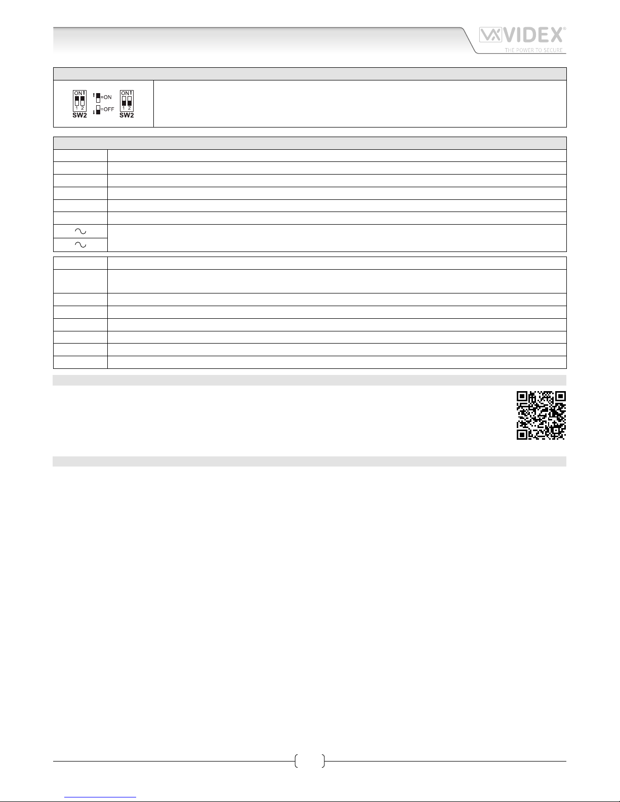
2 WAY DIPSWITCH SW2
The two way dip-switch adjusts the impedance of the video signal. The default setting is “ON” for both
switches (75 Ohm): when there are more videophones in parallel connection (without video distributor)
both switches must be “ON” only on the last videophone (looking at the connection order) while for all
other videophones both switches must be set to “OFF”.
SIGNALS ON CONNECTION BOARD
+V 20Vdc Input/Output (As input 16÷20Vdc 0,5A – as output 20Vdc 0,5A max)
Ground reference for +V terminal.
1 Speech line output from microphone and data signal (Approx. 12V in stand-by, 5V during a conversation)
2 Speech line input toward the loudspeaker (Approx. 12V in stand- by, approx. 3V during a conversation)
V1 Balanced video signal 1 sync.–
V2 Balanced video signal 2 sync.+
24Vac 1A max power input
LB Local call input (5V in standby, 0V to trigger)
SB
Service button (open collector) active low output. The button goes active when the button is pressed
(Open Collector 24Vdc 100mA max)
LD 12Vdc input for door-open LED
2A Speech line input toward the loudspeaker of the parallel telephone (Approx. 12V in stand-by, 3V during a conversation)
3A Output switched ground for parallel telephone
4A Output call tone for parallel telephone
5A Input for door-open command from parallel telephone
12M
12Vdc power supply for Memory Board version (optional)
MEMORY BOARD
This device is also available in the version with memory board (Art.6758/VM).
If you have that version, please refer to the “6200, 6300, 6400 and 6700 Series Memory Board” user manual for
installation and use. The manual is available for download at the following link:
https://www.dropbox.com/s/492p16btyqhxmpu/66250782-EN.pdf?dl=0
TECHNICAL SPECIFICATION
Power Supply: 24Vac in or 20Vdc in
Power consumption: Stand-by: 50mA Max
Operating: 400mA Max
Working Temperature: -10 +50 °C
Page 4
66251550-EN - V1.0 - 15/02/17
4
6700 Series
Art.6758 - Installation instructions
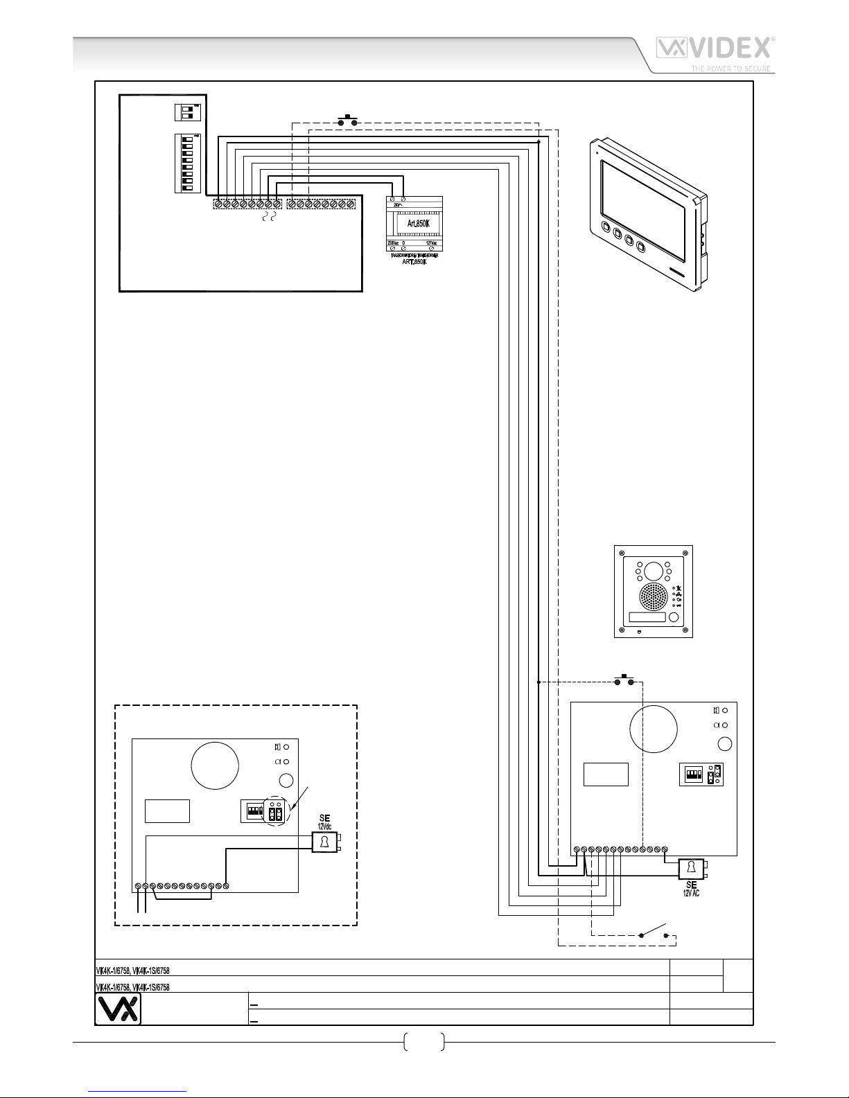
Art.6758 7" Hands free colour display digital videomonitor
Push to
Exit
Local Bell
Door
Monitor
NC
V2
BS
PTE
SL
V1
2
-
1
12Vout
+V
C
NO
432
1
ON
1
Art.4833-1
Using Electric Lock 12Vdc 0.3A Max
Con serratura elettrica 12Vdc 0.3A Max
NC
V2
BS
PTE
SL
V1
2
-
1
12Vout
+V
C
NO
432
1
ON
1
Art.4833-1
Affinche qualsiasi modifica alle impostazioni dei dip switch del
videocitofono o del posto esterno venga riconosciuta dal sistema,
è necessario togliere l'alimentazione di rete all'impianto e
restituirla.
In order to make the system recognize any modification of the
videophone's and outdoor station's dip-switch setting temporarily
disconnect the system from the mains and reconnect
Videx Electronics S.p.A.
Via del Lavoro 1, 63020 Monte Giberto (AP)
Phone: +39 0734 631669 - Fax +39 0734 631669
www.videx.it - info@videx.it
Autore:
Data modifica:
Data creazione:Title:
Notes:
Titolo:
Note:
Cod.File:
Foglio
/11
Marco Rongoni
vk4k67h-002.dw
g
07/02/2017
07/02/2017
1234567812
ON
Address N.
ON
+V
_
1
2
V1
SB
LD2A3A
4A
SW2
SW1
LB
V2
5A
12M
Extension N.
1
Art.6758
1
Page 5

66251550-EN - V1.0 - 15/02/17
5
6700 Series
Art.6758 - Installation instructions
Art.6758 7" Hands free colour display digital videomonitor
Videx Electronics S.p.A.
Via del Lavoro 1, 63020 Monte Giberto (AP)
Phone: +39 0734 631669 - Fax +39 0734 631669
www.videx.it - info@videx.it
Autore:
Data modifica:
Data creazione:Title:
Notes:
Titolo:
Note:
Cod.File:
Foglio
/11
Marco Rongoni
vk8k67h-002.dw
g
07/02/2017
07/02/2017
Local Bell
Push to
Exit
Door
Monitor
Art.8833-1
Using Electric Lock 12Vdc 0.3A Max
Con serratura elettrica 12Vdc 0.3A Max
Art.8833-1
In caso di modifica alle impostazioni dei dip switch del
videocitofono o del posto esterno, togliere temporaneamente
l'alimentazione di rete.
In order to make the system recognize any modification of the
videophone's and outdoor station's dip-switch setting, temporarily
disconnect the system from the mains and reconnect
1234567812
ON
Address N.
ON
+V
_
1
2
V1
SB
LD2A3A
4A
SW2
SW1
LB
V2
5A
12M
Extension N.
1
Art.6758
1
Page 6

66251550-EN - V1.0 - 15/02/17
6
6700 Series
Art.6758 - Installation instructions
Art.6758 7" Hands free colour display digital videomonitor
Using Electric Lock 12Vdc 0.3A Max
Con serratura elettrica 12Vdc 0.3A Max
432
1
ON
J1
VR4KAMK-1
Art.140
J2
Videx Electronics S.p.A.
Via del Lavoro 1, 63846 Monte Giberto (FM)
Phone: +39 0734 631669 - Fax +39 0734 631669
www.videx.it - info@videx.it
Autore:
Data modifica:
Data creazione:Title:
Notes:
Titolo:
Note:
Cod.File:
Foglio
/11
Marco Rongoni
vrvk67h-001.dw
g
07/02/2017
07/02/2017
Push to
Exit
Affinche qualsiasi modifica alle impostazioni dei dip switch del
videocitofono o del posto esterno venga riconosciuta dal sistema,
è necessario togliere l'alimentazione di rete all'impianto e
restituirla.
In order to make the system recognize any modification of the
videophone's and outdoor station's dip-switch setting temporarily
disconnect the system from the mains and reconnect
432
1
ON
J1
VR4KAMK-1
Art.140
J2
Local Bell
CoaxNCSL
ON
Art.VR4KCM
1
1234567812
ON
Address N.
ON
+V
_
1
2
V1
SB
LD2A3A
4A
SW2
SW1
LB
V2
5A
12M
Extension N.
1
Art.6758
1
Page 7

66251550-EN - V1.0 - 15/02/17
7
6700 Series
Art.6758 - Installation instructions
Art.6758 7" Hands free colour display digital videomonitor
Videx Electronics S.p.A.
Via del Lavoro 1, 63020 Monte Giberto (AP)
Phone: +39 0734 631669 - Fax +39 0734 631669
www.videx.it - info@videx.it
Autore:
Data modifica:
Data creazione:Title:
Notes:
Titolo:
Note:
Cod.File:
Foglio
/11
Marco Rongoni
vk4k67h-012.dw
g
07/02/2017
07/02/2017
432
1
ON
1
Art.4833-1
Using Electric Lock 12Vdc 0.3A Max
Con serratura elettrica 12Vdc 0.3A Max
NC
V2
BS
PTE
SL
V1
2
-
1
12Vout
+V
C
NO
4321
ON
1
Art.4833-1D
Push
to
Exit
1
Affinche qualsiasi modifica alle impostazioni dei dip switch del
videocitofono o del posto esterno venga riconosciuta dal sistema,
è necessario togliere l'alimentazione di rete all'impianto e
restituirla.
In order to make the system recognize any modification of the
videophone's and outdoor station's dip-switch setting temporarily
disconnect the system from the mains and reconnect
Local Bell
Local Bell
1234567812
ON
Address N.
ON
+V
_
1
2
V1
SB
LD
2A
3A
4A
SW2
SW1
LB
V2
5A
12M
Extension N.
1
Art.6758
2
1234567812
ON
Address N.
ON
+V
_
1
2
V1
SB
LD
2A
3A
4A
SW2
SW1
LB
V2
5A
12M
Extension N.
1
Art.6758
1
Page 8

66251550-EN - V1.0 - 15/02/17
8
6700 Series
Art.6758 - Installation instructions
Art.6758 7" Hands free colour display digital videomonitor
Videx Electronics S.p.A.
Via del Lavoro 1, 63846 Monte Giberto (FM)
Phone: +39 0734 631669 - Fax +39 0734 631669
www.videx.it - info@videx.it
Autore:
Data modifica:
Data creazione:Title:
Notes:
Titolo:
Note:
Cod.File:
Foglio
/11
Marco Rongoni
vk8k67h-008.dw
g
07/02/2017
07/02/2017
Using Electric Lock 12Vdc 0.3A Max
Con serratura elettrica 12Vdc 0.3A Max
Art.8833-1
In caso di modifica alle impostazioni dei dip switch del
videocitofono o del posto esterno, togliere temporaneamente
l'alimentazione di rete.
In order to make the system recognize any modification of the
videophone's and outdoor station's dip-switch setting, temporarily
disconnect the system from the mains and reconnect
Push to
Exit
Art.8833-1
+
Art.8800
1234567812
ON
Address N.
ON
+V
_
1
2
V1
SB
LD
2A
3A
4A
SW2
SW1
LB
V2
5A
12M
Extension N.
1
Art.6758
3
1234567812
ON
Address N.
ON
+V
_
1
2
V1
SB
LD
2A
3A
4A
SW2
SW1
LB
V2
5A
12M
Extension N.
1
Art.6758
2
1234567812
ON
Address N.
ON
+V
_
1
2
V1
SB
LD
2A
3A
4A
SW2
SW1
LB
V2
5A
12M
Extension N.
1
Art.6758
1
Page 9

66251550-EN - V1.0 - 15/02/17
9
6700 Series
Art.6758 - Installation instructions
1. In order to install the videophone, it is necessary to remove the cover, which contains all the electronics, from the base: press
lightly on the right part of the videophone and simultaneously pulling outwards the left part as shown in Fig. 1.
2. Put the base of the unit on the wall at approx 135cm from the nished oor to match the points for the xing holes “A” (Fig. 2)
remembering that the wires “D” (Fig. 3) must be fed through the large hole “E” (Fig. 3). If you use the ush mounting box 503,
embed it into the wall vertically at approx. 140cm from the nished oor and the base.
3. Following Fig. 3, make the holes “A”, insert the wall plugs “B” and x the base with the screws “C” feeding the wires “D”
through the hole “E”. If you have used the box 503, x the base to the wall through the holes “F” using the screws “C”.
4. As shown in Fig. 4, connect the wires to the removable terminals following the provided installation diagram. Connect the terminal
blocks to the electronics contained in the cover as shown in Fig. 5. Test system before closing.
Contrast and hue trimmers can be adjusted only if the videophone is open. To activate the display and see changes use the
“Camera Recall” function by pressing
button.
Note: while testing the system, it is advisable to hold the cover with your hand.
5. Once testing is complete and all the necessary adjustments are made, close the unit as shown in Fig. 6: rst hook in the right
part and then the left part until you hear a click.
1
2
Fig. 1
Fig. 4
135cm
Fig. 2
Fig. 5
C
C
E
F
F
A
A
B
B
Fig. 3
2
1
Fig. 6
6700 Series Wall mounting instructions
Page 10

66251550-EN - V1.0 - 15/02/17
10
6700 Series
Art.6758 - Installation instructions
Notes
Page 11

66251550-EN - V1.0 - 15/02/17
11
6700 Series
Art.6758 - Installation instructions
Notes
Page 12

MANUFACTURER
VIDEX ELECTRONICS S.P.A.
Via del Lavoro, 1 - 63846 Monte Giberto (FM) Italy
Tel (+39) 0734 631669 - Fax (+39) 0734 632475
www.videx.it - info@videx.it
CUSTOMER SUPPORT
All Countries:
VIDEX ELECTRONICS S.P.A.
www.videx.it - technical@videx.it
Tel: +39 0734-631669 - Fax: +39 0734-632475
UK Customers:
VIDEX SECURITY LTD
www.videx-security.com
Tech Line: 0191 224 3174 - Fax: 0191 224 1559
The product is CE marked demonstrating its conformity and is for distribution
within all member states of the EU with no restrictions. This product follows
the provisions of the European Directives 2014/30/EU (EMC); 2014/35/EU
(LVD); 2011/65/EU (RoHS): CE marking 93/68/EEC.
Main UK oce:
VIDEX SECURITY LTD
1 Osprey Trinity Park
Trinity Way
LONDON E4 8TD
Phone: (+44) 0870 300 1240
Fax: (+44) 020 8523 5825
www.videx-security.com
marketing@videx-security.com
Northern UK oce:
VIDEX SECURITY LTD
Unit 4-7
Chillingham Industrial Estate
Chapman Street
NEWCASTLE UPON TYNE - NE6 2XX
Tech Line: (+44) 0191 224 3174
Phone: (+44) 0870 300 1240
Fax: (+44) 0191 224 1559
Greece oce:
VIDEX HELLAS Electronics
48 Filolaou Str.
11633 ATHENS
Phone: (+30) 210 7521028
(+30) 210 7521998
Fax: (+30) 210 7560712
www.videx.gr
videx@videx.gr
Danish oce:
VIDEX DANMARK
Hammershusgade 15
DK-2100 COPENHAGEN
Phone: (+45) 39 29 80 00
Fax: (+45) 39 27 77 75
www.videx.dk
videx@videx.dk
Benelux oce:
NESTOR COMPANY NV
E3 laan, 93
B-9800 Deinze
Phone: (+32) 9 380 40 20
Fax: (+32) 9 380 40 25
www.videx.be
info@videx.be
Dutch oce:
NESTOR COMPANY BV
Business Center Twente (BCT)
Grotestraat, 64
NL-7622 GM Borne
www.videxintercom.nl
info@videxintercom.nl
 Loading...