

Page 1
66251125-EN - V1.2 - 31/10/16
1
6200 Series
Art.6276 - Installation instructions
Art.6276 3.5" colour display videophone
27 mm 144 mm
182 mm
Fig. 1
+VD
+20
V1
V/V2
GNDV
L
–
LB
AL
DOL
EXTC
SW
SW
DSW1 DSW2
PT1
PT2
VR1
PT3
SW2
A
I
B
D
G
E
H
F
C
Fig. 2
ART.6276 VX2200 6200 SERIES VIDEOPHONE FOR SYSTEMS
USING COMPOSITE VIDEO SIGNAL COAX OR BALANCED
TWISTED PAIR
DESCRIPTION
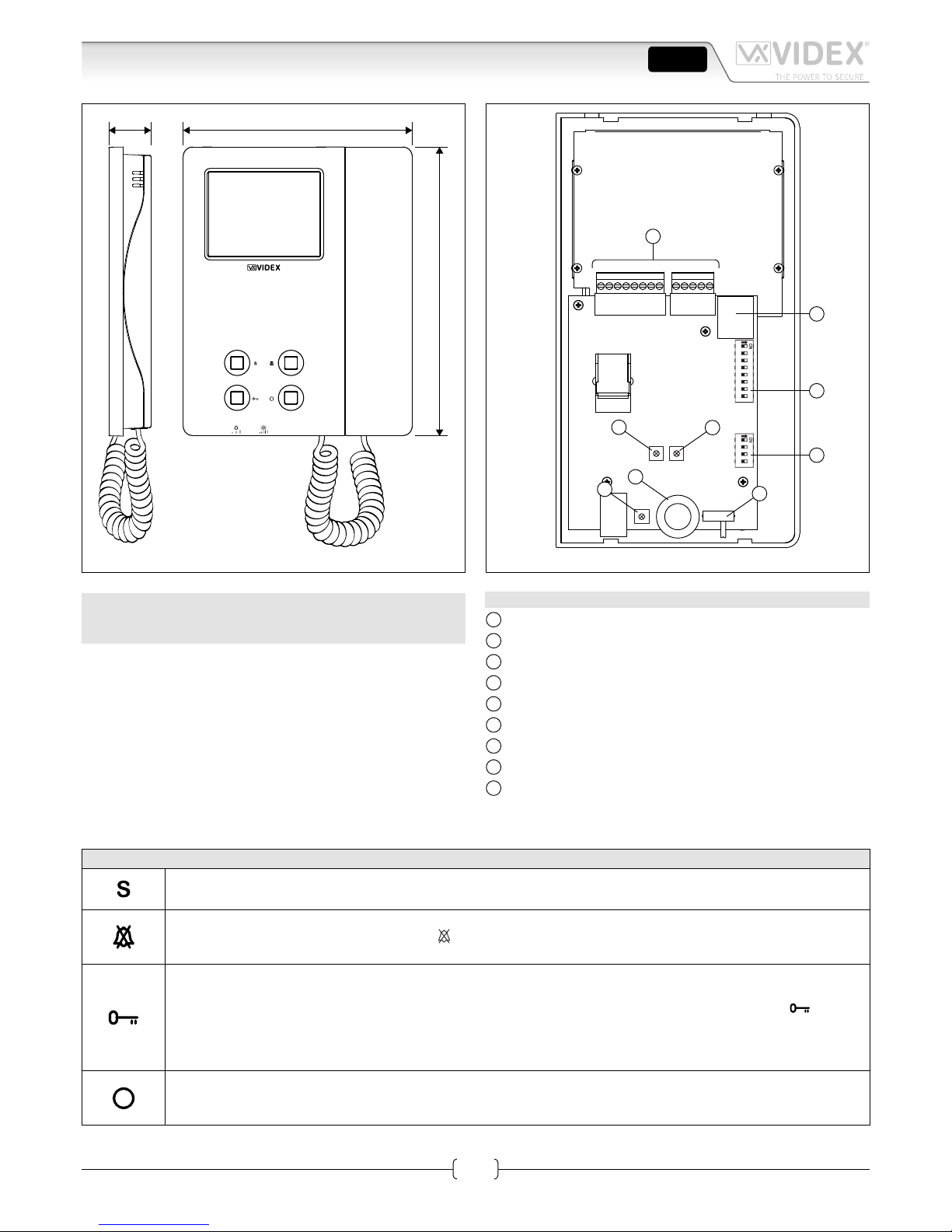
Surface mount videophone incorporating a 3.5” Hi-Res full colour active matrix LCD monitor, with “camera recall”, “door open/
concierge call”, “service” and “privacy” button.
2 LED’s one for generic use (door opening usually) and one to
indicate privacy service enabled.
Programmable settings: privacy duration, video mode (coax or
balanced), melody and number of rings.
Adjustments: call tone volume (3 levels), microphone volume,
picture hue, contrast and brightness.
LEGEND
A
Connection terminals
B
8 Way dip switch bank to set videophone address
C
4 Way dip switch bank to set video mode
D
Contrast adjustment trimmer
E
Hue adjustment trimmer
F
Microphone volume adjustment trimmer
G
Brightness control sliding wheel
H
Call tone volume switch
I
RJ-45 connector
PUSH BUTTONS
Service button
When pressed, shorts terminal SW to SW (Max 24 Vdc 50mA).
Privacy service
Press to enable the privacy service. The LED turns on. The service is deactivated by pressing again the same button or when the programmed time expires.
Door Open Push Button
• During a conversation, operation of this button will release the door from where the call originated. This will be
conrmed by an acoustic tone. If terminal DOL is connected, the “door open” LED under the symbol will also
illuminate.
• When the system is in stand-by, picking up the handset and pressing the buttons will book a call to the concierge
(If available).
Camera recall
When the system is in standby (no calls on the system), pick up the handset then press this button to open the
SPEECH/VIDEO to the door station. Press as many time as the ID value of the door panel to connect to.
ENG
Page 2
66251125-EN - V1.2 - 31/10/16
2
6200 Series
Art.6276 - Installation instructions
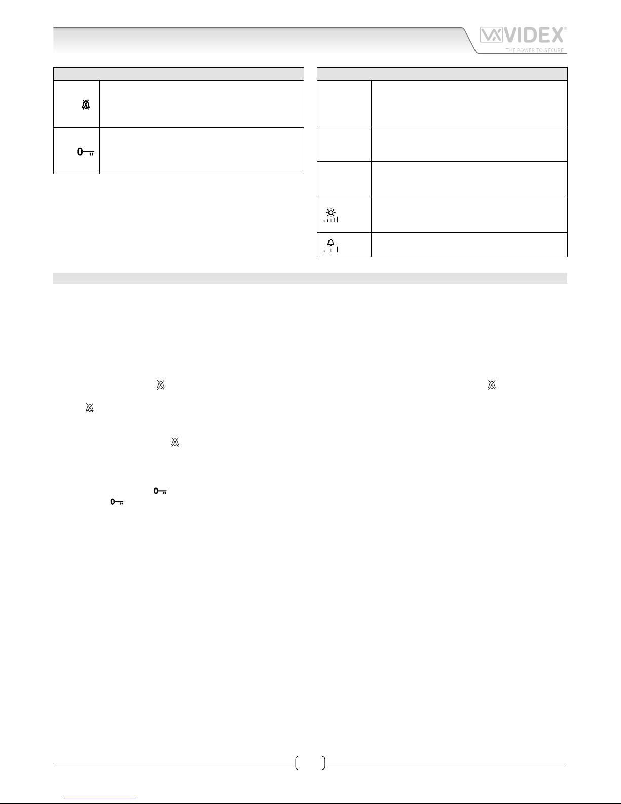
LEDS FIG. 1
LED
Privacy on LED
It illuminates when the privacy service is enabled,
when pressing the service button or during programming mode.
LED
Generic use LED
It is controlled from the terminal DOL.
Normally used to signal the door status (open or
closed).
CONTROLS FIG. 1 AND FIG. 2
PT1
Contrast adjustment trimmer*
Rotate anticlockwise to increase or clockwise to
decrease.
*Not available in some LCD versions.
PT2
Hue adjustment trimmer
Rotate anticlockwise to increase or clockwise to
decrease.
VR1
Microphone volume adjustment trimmer
Rotate anticlockwise to decrease or clockwise to
increase.
PT3
Brightness control sliding wheel
Rotate anticlockwise to increase or clockwise to
decrease (when videophone is closed).
SW2
Call tone volume switch
3 levels: low, medium and high.
PROGRAMMING
The programmable settings are:
• Privacy service duration (from 15 minutes to 20 hours or innte);
• Melody (9 available);
• Number of rings (3 or 6);
• Video mode (coax or balanced);
• Videophone address (Phone ID).
TO SET PRIVACY SERVICE DURATION
1. Press and keep pressed
button for 10 seconds to enter privacy service duration programming mode: the LED turns on and
the unit emits a “beep“;
2. Press button as many times as required. Each press is equal to 15 minutes: the unit emits a “beep“ every time the button is
pressed. I.E.: press 4 times for 1 hour, 12 for 3 hours. Default: innite. Max value: 20 hours. To program innite privacy time don’t
press any buttons;
3. Wait for some seconds: the LED turns o and the unit emits a “beep“ that conrms the new setting is properly stored;
4. The unit returns to stand-by mode.
TO SET MELODY
1. Press and keep pressed button for 10 seconds until the unit plays the current programmed melody and emits a “beep” at the end.
2. Press again button to listen to the available melodies (maximum 9);
3. Once the selected melody has been reached, wait 5 seconds for a “beep”;
4. The new melody will be stored.
Note: To set the melody it is required that the videophone is connected in a system where the +20Vdc voltage from Art.893N1 is
always enabled.
TO SET THE NUMBER OF RINGS 6 OR 3:
Default setting is 6, to set 3 proceed as follows:
1. Turn o the videophone by unplugging the connector from the PCB;
2. Make a short between terminals GNDV and LB on the connector;
3. Plug the connector in and wait for a beep before removing the short;
4. To go back to 6 rings, do the same but two “beeps” will be emitted.
Art.6276 3.5" colour display videophone
Page 3
66251125-EN - V1.2 - 31/10/16
3
6200 Series
Art.6276 - Installation instructions
Art.6276 3.5" colour display videophone
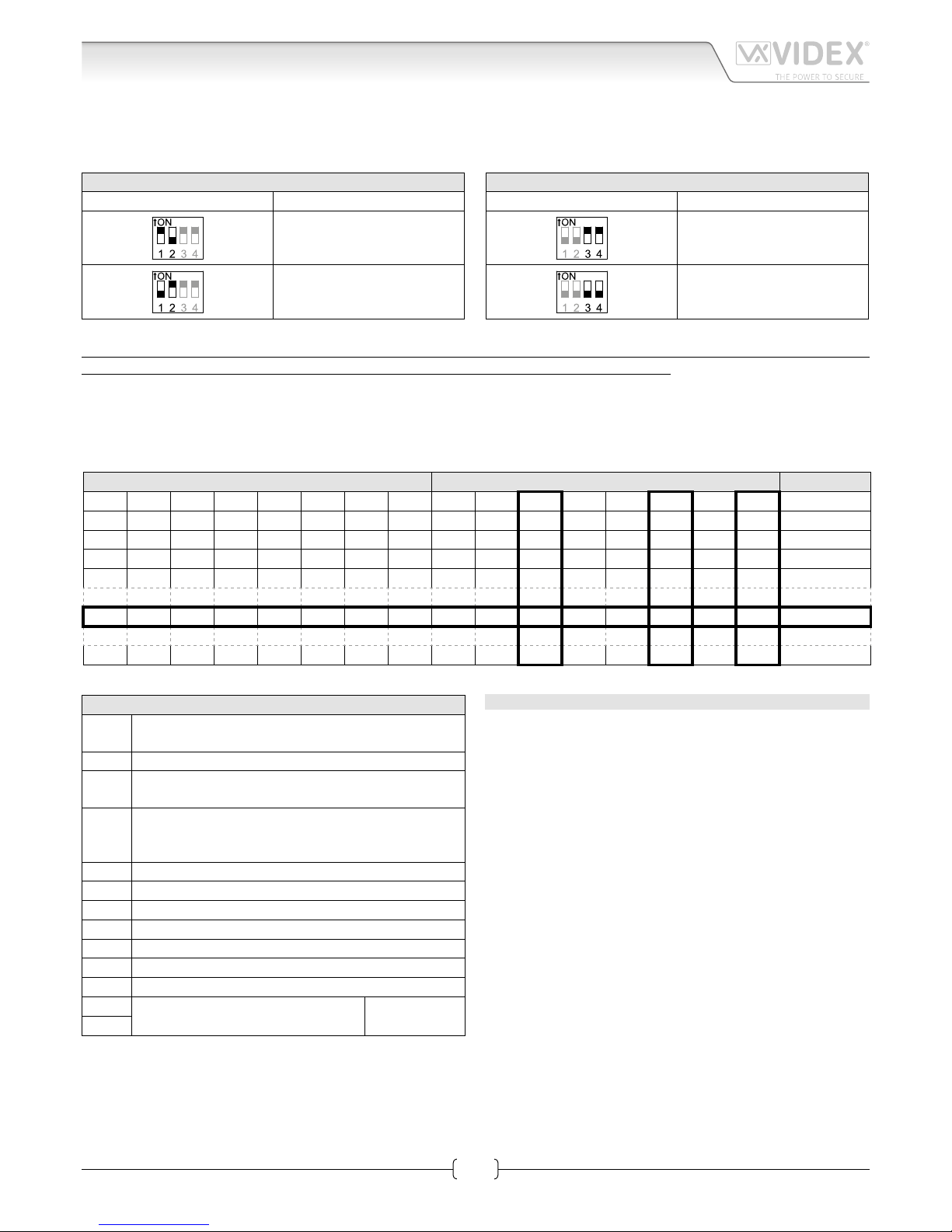
TO SET THE VIDEO MODE AND TERMINATION
The videophone can operate with either composite video signal (coax cable) or balanced video signal (two wires). Switches 1 & 2 of
DSW2 are used to set video mode while switches 3 & 4 are for video termination.
VIDEO MODE DSW2
Switches 1,2 Mode
Coax
Balanced
75 OHM VIDEO TERMINATION DSW2
Switches 3,4 Termination
Enabled
Disabled
Switches 3 and 4 adjust the video signal impedance. when using more than one videomonitor in parallel (without a video
splitter) put both switches in the OFF position on all but the last videomonitor (end of line).
VIDEOMONITOR/INTERCOM ADDRESS, VIDEO MODE AND TERMINATION SETUP DSW1
Each intercom is addressed in binary (PHONE ID) using the 8 way dipswitches located on the rear of the unit. Each switch corresponds to one bit which can have a value 0 (OFF) or 1 (ON). Each bit corresponds to a decimal weight depending on the position:
Switch 1 = decimal 1, 2=2, 3=4, 4=8, 5=16, 6=32, 7=64, 8=128. I.E. to set the address 37, put switches 1, 3 and 6 on (1+4+32=37).
SWITCHES DECIMAL WEIGHT ADDRESS
8 7 6 5 4 3 2 1 128 64 32 16 8 4 2 1
OFF OFF OFF OFF OFF OFF OFF ON 0 0 0 0 0 0 0 1 1
OFF OFF OFF OFF OFF OFF ON OFF 0 0 0 0 0 0 1 0 2
OFF OFF OFF OFF OFF OFF ON ON 0 0 0 0 0 0 1 1 3
OFF OFF OFF OFF OFF ON OFF OFF 0 0 0 0 0 1 0 0 4
OFF OFF ON OFF OFF ON OFF ON 0 0 1 0 0 1 0 1 37
ON OFF ON ON OFF ON OFF OFF 1 0 1 1 0 1 0 0 180
CONNECTION TERMINALS SIGNALS
+VD
12Vdc output to supply coax video distributor
Art.894N
+20 Video power supply 17÷20Vdc
V1
Balanced video signal V1 sync. (balanced video signal
mode)
V/V2
Balanced video signal V2 sync. (balanced video signal
mode)
Composite video signal (coax video signal mode)
GNDV Video power supply ground reference
L BUS line
– BUS line ground reference
LB Local bell input (active low)
AL Alarm input (active low)
DOL 12Vdc input to supply Aux LED
EXTC Call tone output for extension sounder (Art.512A)
SW
Service button connection
Max 24 Vdc
50mA
SW
TECHNICAL SPECIFICATION
Working Voltage: 17÷20Vdc
Power Consumption: 200mA during a call
120mA during a conversation
Working Temperature: -10°C +50°C
Page 4

66251125-EN - V1.2 - 31/10/16
4
6200 Series
Art.6276 - Installation instructions
USING RJ45 PLUG TO CONNECT THE VIDEOPHONE
EIA/TIA568B
1
2
3
4
5
6
7
8
o
O
g
B
b
O
br
BR
8
7
6
5
4
3
2
1
BR
br
G
b
B
g
O
o
EIA/TIA-568B
RJ-45 pin VX2200 Signal
1 and 2 (white-orange / orange) L
3 and 4 (white-green / blue) –
5 and 6 (white-blue / green) +
7 (white-brown) V1
8 (brown) V2
EIA/TIA568A
1
2
3
4
5
6
7
8
g
G
o
B
b
O
br
BR
8
7
6
5
4
3
2
1
BR
br
O
b
B
o
G
g
EIA/TIA-568A
RJ-45 pin VX2200 Signal
1 and 2 (white-green / green) L
3 and 4 (white-orange / blue) –
5 and 6 (white-blue / orange) +
7 (white-brown) V1
8 (brown) V2
NOTE: DO NOT USE CROSS OVER CABLES.
IMPORTANT NOTE: SOLID COPPER CABLES MUST BE USED. COPPER COATED STEEL CCS AND COPPER COATED
ALUMINIUM CCA CAN NOT BE USED ON THE SYSTEM.
MEMORY BOARD
This device is also available in the version with memory board (Art.6276/VM).
If you have that version, please refer to the “6200, 6300, 6400 and 6700 Series Memory Board” user manual for
installation and use. The manual is available for download at the following link:
https://www.dropbox.com/s/492p16btyqhxmpu/66250782-EN.pdf?dl=0
Art.6276 3.5" colour display videophone
CUSTOMER SUPPORTMANUFACTURER
All Countries:
VIDEX ELECTRONICS S.P.A.
www.videx.it - technical@videx.it
Tel: +39 0734-631669
Fax: +39 0734-632475
VIDEX ELECTRONICS S.P.A.
Via del Lavoro, 1 - 63846 Monte Giberto (FM) Italy
Tel (+39) 0734 631669 - Fax (+39) 0734 632475
www.videx.it - info@videx.it
UK Customers:
VIDEX SECURITY LTD
www.videx-security.com
Tech Line: 0191 224 3174
Fax: 0191 224 1559
The product is CE marked demonstrating its conformity and is for distribution
within all member states of the EU with no restrictions. This product follows
the provisions of the European Directives 2014/30/EU (EMC); 2014/35/EU
(LVD); 2011/65/EU (RoHS): CE marking 93/68/EEC.
Page 5

66251125-EN - V1.2 - 31/10/16
5
6200 Series
Art.6276 - Installation instructions
Art.6276 3.5" colour display videophone
Page 6

66251125-EN - V1.2 - 31/10/16
6
6200 Series
Art.6276 - Installation instructions
Art.6276 3.5" colour display videophone
ON/OFF
+
13V
ART.521B
115
0
swsw
+B
+12
_
L
BS
SL
NCCNO
TRD
PTE
V1
V2 / V
GNDV
12T
B.V.
coax
others
316x
GND
Art.4202RV
A
SE
12Vac
ART.893N1
0
L-+-
V1V2
L - + - V1 V2
C
VID
A
L - + - V1 V2
1.50mm21.50mm21.50mm21.50mm21.00mm21.00mm
2
Address N. 3
Art.6276
Address N. 1
Art.6378
1/2
Videx Electronics S.p.A.
Via del Lavoro, 1 - 63846 Monte Giberto (FM)
Phone: +39 0734 631669 - Fax +39 0734 631669
www.videx.it - info@videx.it
Title:
Notes:
Titolo:
Note:
Autore:
Data modifica:
Data creazione:
Cod.File:
Foglio
/
224KVD139A.dwg
Marco@videx.it
20/10/2016
16/09/2016
11
123456781234
ON
Address N.
BALANCED
ON
+VD
+20
V1
V/V2
GNDV
-
LB
DOL
EXTC
SW
SW
12Vo
SW2 SW1
AL
L
12Vi
VM
2
Art.6778
123456781234
ON
Address N.
BALANCED
ON
+VD
+20
V1
V/V2
GNDV
-
LB
DOL
EXTC
SW
SW
12Vo
SW2 SW1
AL
L
12Vi
VM
4
Art.6778
Page 7

66251125-EN - V1.2 - 31/10/16
7
6200 Series
Art.6276 - Installation instructions
Art.6276 3.5" colour display videophone
L - + - V1 V2
L-+-
V1V2
C
VID
A = MAX 40mt
A
MAX 400mt
L - + - V1 V2
L - + - V1 V2
C
VID
A
Address N. 6
Art.6276
Address N. 5
Art.6276
Address N. 7
Art.6276
Address N. 8
Art.6276
Address N. 12
Art.6276
Address N. 11
Art.6276
Address N. 9
Art.6378
Address N. 10
Art.6378
2/2
L-+-
V1V2
L - + - V1 V2
VID
OClose
Page 8

66251125-EN - V1.2 - 31/10/16
8
6200 Series
Art.6276 - Installation instructions
6200 Series Videophone wall mounting instructions
1. In order to install the videophone, it is necessary to remove the cover, which contains all the electronics, from the base: rstly
disconnect the handset from the videophone (by removing its plug from the videophone), then press lightly the bottom part of
the videophone and simultaneously pulling outwards the upper part as shown in Fig. 1.
2. Put the base of the unit on the wall at approx 135cm from the nished oor to mark the points for the xing holes “A” (Fig. 2)
remembering that the wires “D” (Fig. 3) must be fed through the hole “E” (Fig. 3). If you use the ush mounting box 503, embed
it into the wall vertically at approx. 140cm from the nished oor and the base.
3. Following Fig. 3, make the holes “A”, insert the wall plugs “B” and x the base with the screws “C” feeding the wires “D” into
the hole “E”. If you have used the box 503, x the base to the wall through the holes “F” using the screws “C”.
4. As shown in Fig. 4A, connect the wires to the removable terminals following the provided installation diagram. Connect the terminal blocks to the electronics contained in the cover as shown in Fig. 4B. Reinsert the handset and test system before closing.
Note: Contrast and hue trimmers can be adjusted only if the videophone is open. Note while testing the system, it is
advisable to hold the cover with your hand closing manually the hook switch of the handset (see Fig. 4B reference “G”).
5. Once testing is complete and all the necessary adjustments are made, disconnect the handset from the cover and close the unit
as shown in Fig. 5: rst hook it on the bottom then push in the top until you hear the clip.
6. Reconnect the handset and hang it as shown in Fig. 6.
1
2
Fig. 1
A
B
G
Fig. 4
135cm
Fig. 2
1
2
Fig. 5
A
B
A
B
D
F
E
F
C
C
Fig. 3
Fig. 6
 Loading...