

Page 1
66251140-EN - V1.3 - 15/06/16
1
6200 Series
Art.6231 - Installation instructions
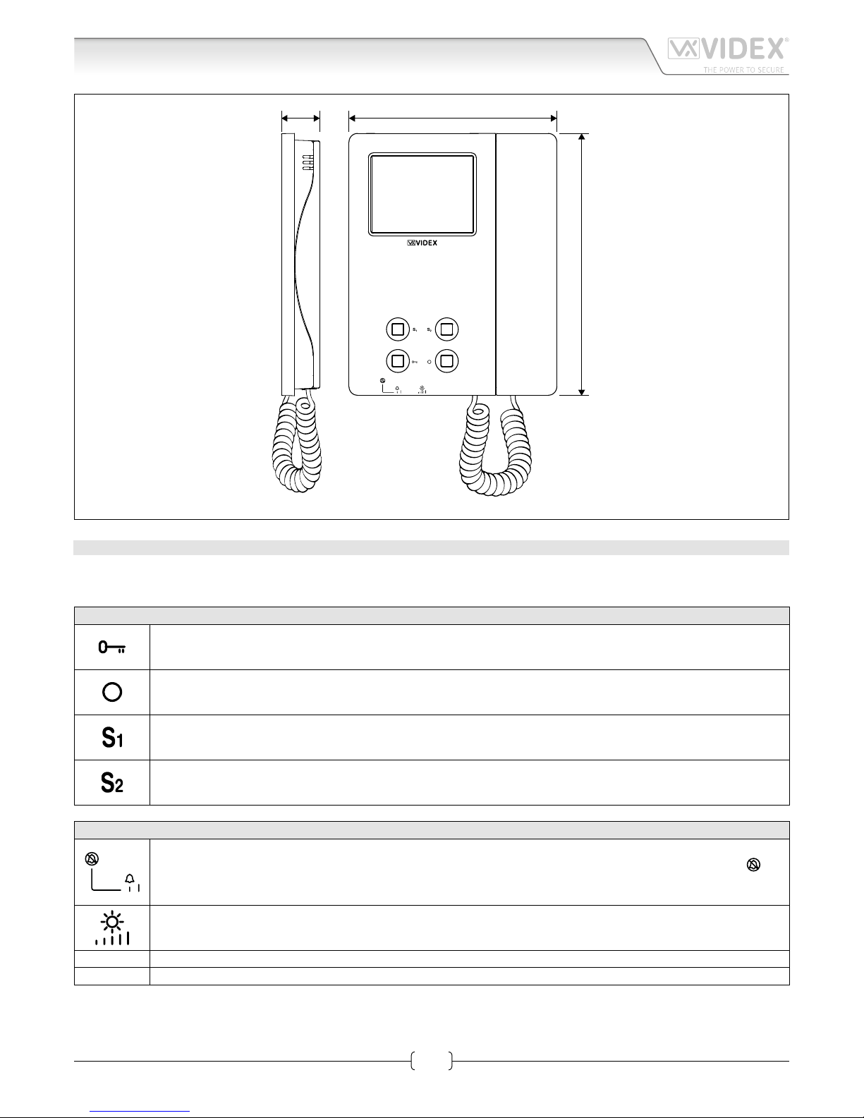
Art.6231 3.5" colour display videophone
27 mm 144 mm
182 mm
Fig. 1
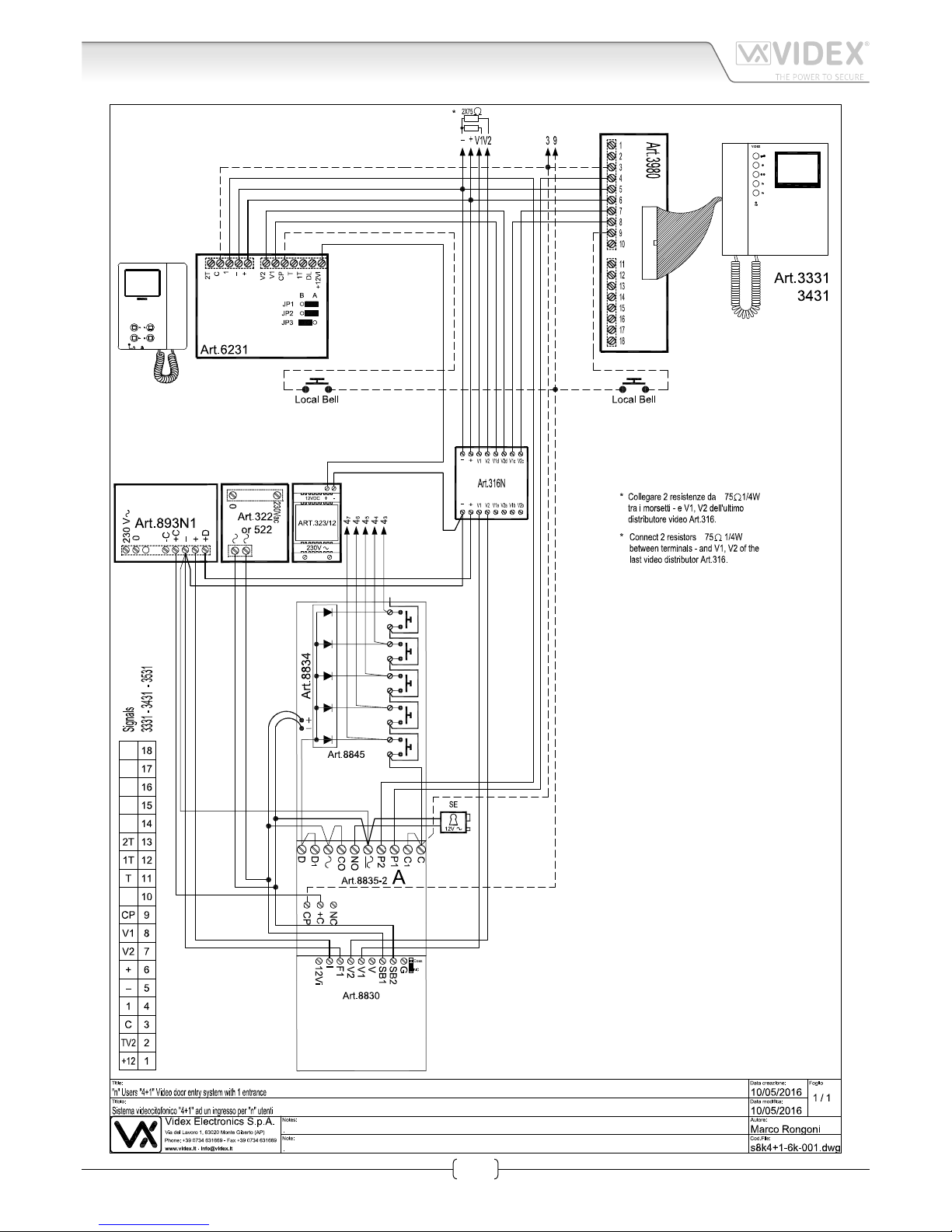
VIDEOPHONE FOR 4+1 SYSTEMS WITH BALANCED VIDEO SIGNAL NON COAX ART.6231
Videophones with 3.5” colour LCD TFT monitor for video systems using balanced video signal (non coax).
Are made from white ABS shockproof plastic and the installation is surface mounting.
PUSH BUTTONS
Activates the electric lock (door-open) only when the videophone is on and the handset is picked up.
Switches on the system and displays the video from the outdoor station on the videophone (camera recall).
By picking up the handset and pressing the “door-open” push button it is possible to open the door.
Service push button or camera recall depending on JP1 jumper position (see Table 1 - Jumper settings for Art.6231
on page 2).
Service push button or camera recall depending on JP2 jumper position (see Table 1 - Jumper settings for Art.6231
on page 2).
CONTROLS
Switch to adjust the call tone volume and enable the privacy service. In the middle position the volume is standard,
in right position the volume is high while in the left position privacy is enable: the LED under the symbol
will
illuminate. When the service is enabled the videophone receives calls showing the video from the door panel but
doesn’t ring. The privacy mode may be disabled moving the switch to the middle or right position.
Adjusts the picture brightness: right rotation to increase, left rotation to decrease.
PT3 Contrast (internal trimmer – rotate clockwise to increase, anticlockwise to decrease).
PT2 Hue (internal trimmer – rotate clockwise to increase, anticlockwise to decrease).
Page 2
66251140-EN - V1.3 - 15/06/16
2
6200 Series
Art.6231 - Installation instructions
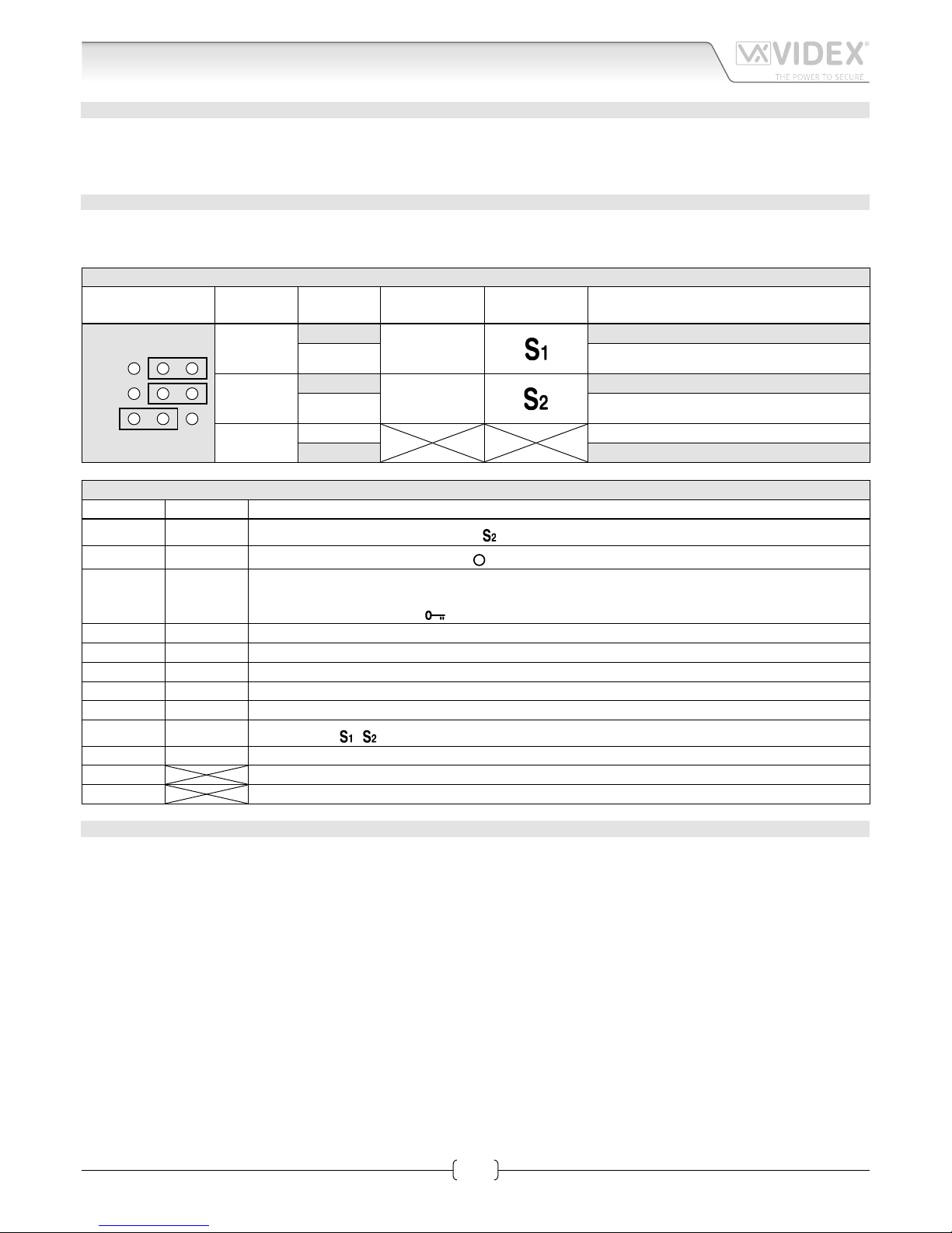
JUMPER SETTINGS
There are 3 internal jumpers (JP1-JP3). The rst 2 jumpers are for service push button functions the third sets the videophone as
either a master or a slave (this function is often used for videophones with parallel connections). Table 1 on page 2 shows the
default conguration for these jumpers and the available congurations.
TERMINALS AND RELEVANT SIGNALS
Table 2 on page 2 shows the functions available on the terminals. The table also shows (for compatibility with older systems)
the terminal markings used on the 900 series and 3000Series.
Table 1 - Jumper settings for Art.6231
Jumper
Jumper
position
Pin connector Button Push button function
B A
JP1
JP2
JP3
JP1
A
1T
Linked to pin connector “T”.
B Camera recall.
JP2
A
2T
Linked to pin connector “T”.
B Camera recall.
JP3
A Monitor switched o during call tone.
B Monitor switched on during call tone.
Table 2 - Art.6231 videophone signals
Art.6231 Art.3X31 Signal description
2T 13
See Table 1 on page 2 - push button
C 3
Camera recall button - push button
1 4
Call tone input.
Input/Output speech line.
Door opening – push button
5 Negative power input 0 Volt.
+ 6 Positive power input +15 - 20Vdc 0.45A.
V2 7 Video input +sync.
V1 8 Video input –sync.
CP 9 Local call tone input (at bell etc.).
T 11
Push buttons
, common terminal.
1T 12 See Table 1 on page 2 - push button
DL Door open LED +12Vdc input
12VI 12Vdc power input for LED privacy
TECHICAL SPECIFICATION
Voltages: 20Vdc (+2-5V)
Power consuption: Stand-by: 0mA
Operating: 100mA max
Art.6231 3.5" colour display videophone
Page 3
66251140-EN - V1.3 - 15/06/16
3
6200 Series
Art.6231 - Installation instructions
Art.6231 3.5" colour display videophone
Page 4

66251140-EN - V1.3 - 15/06/16
4
6200 Series
Art.6231 - Installation instructions
Art.6231 3.5" colour display videophone
Page 5

66251140-EN - V1.3 - 15/06/16
5
6200 Series
Art.6231 - Installation instructions
6200 Series Videophone wall mounting instructions
1. In order to install the videophone, it is necessary to remove the cover, which contains all the electronics, from the base: rstly
disconnect the handset from the videophone (by removing its plug from the videophone), then press lightly the bottom part of
the videophone and simultaneously pulling outwards the upper part as shown in Fig. 1.
2. Put the base of the unit on the wall at approx 135cm from the nished oor to mark the points for the xing holes “A” (Fig. 2)
remembering that the wires “D” (Fig. 3) must be fed through the hole “E” (Fig. 3). If you use the ush mounting box 503, embed
it into the wall vertically at approx. 140cm from the nished oor and the base.
3. Following Fig. 3, make the holes “A”, insert the wall plugs “B” and x the base with the screws “C” feeding the wires “D” into
the hole “E”. If you have used the box 503, x the base to the wall through the holes “F” using the screws “C”.
4. As shown in Fig. 4A, connect the wires to the removable terminals following the provided installation diagram. Connect the terminal blocks to the electronics contained in the cover as shown in Fig. 4B. Reinsert the handset and test system before closing.
Note: Contrast and hue trimmers can be adjusted only if the videophone is open. Note while testing the system, it is
advisable to hold the cover with your hand closing manually the hook switch of the handset (see Fig. 4B reference “G”).
5. Once testing is complete and all the necessary adjustments are made, disconnect the handset from the cover and close the unit
as shown in Fig. 5: rst hook it on the bottom then push in the top until you hear the clip.
6. Reconnect the handset and hang it as shown in Fig. 6.
1
2
Fig. 1
A
B
G
Fig. 4
135cm
Fig. 2
1
2
Fig. 5
A
B
A
B
D
F
E
F
C
C
Fig. 3
Fig. 6
Page 6

66251140-EN - V1.3 - 15/06/16
6
6200 Series
Art.6231 - Installation instructions
Note
Page 7

66251140-EN - V1.3 - 15/06/16
7
6200 Series
Art.6231 - Installation instructions
Note
Page 8

MANUFACTURER
VIDEX ELECTRONICS S.P.A.
Via del Lavoro, 1 - 63846 Monte Giberto (FM) Italy
Tel (+39) 0734 631669 - Fax (+39) 0734 632475
www.videx.it - info@videx.it
CUSTOMER SUPPORT
All Countries:
VIDEX ELECTRONICS S.P.A.
www.videx.it - technical@videx.it
Tel: +39 0734-631669 - Fax: +39 0734-632475
UK Customers:
VIDEX SECURITY LTD
www.videx-security.com
Tech Line: 0191 224 3174 - Fax: 0191 224 1559
The product is CE marked demonstrating its conformity and is for distribution
within all member states of the EU with no restrictions. This product follows
the provisions of the European Directives 2014/30/EU (EMC); 2014/35/EU
(LVD); 2011/65/EU (RoHS): CE marking 93/68/EEC.
Main UK oce:
VIDEX SECURITY LTD
1 Osprey Trinity Park
Trinity Way
LONDON E4 8TD
Phone: (+44) 0870 300 1240
Fax: (+44) 020 8523 5825
www.videx-security.com
marketing@videx-security.com
Northern UK oce:
VIDEX SECURITY LTD
Unit 4-7
Chillingham Industrial Estate
Chapman Street
NEWCASTLE UPON TYNE - NE6 2XX
Tech Line: (+44) 0191 224 3174
Phone: (+44) 0870 300 1240
Fax: (+44) 0191 224 1559
Greece oce:
VIDEX HELLAS Electronics
48 Filolaou Str.
11633 ATHENS
Phone: (+30) 210 7521028
(+30) 210 7521998
Fax: (+30) 210 7560712
www.videx.gr
videx@videx.gr
Danish oce:
VIDEX DANMARK
Hammershusgade 15
DK-2100 COPENHAGEN
Phone: (+45) 39 29 80 00
Fax: (+45) 39 27 77 75
www.videx.dk
videx@videx.dk
Benelux oce:
VIDEX BENELUX
E3 Iaan, 93
B-9800 DEINZE
Phone: (+32) 9 380 40 20
Fax: (+32) 9 380 40 25
www.videxbenelux.be
info@videxbenelux.be
 Loading...