

Page 1
30
5000 SERIES SLIM LINE VIDEO MONITORS
VIDEOCITOFONI SERIE 5000 LINEA SLIM
10 55
170
153
204
187
1
2
3
4
164
130
34
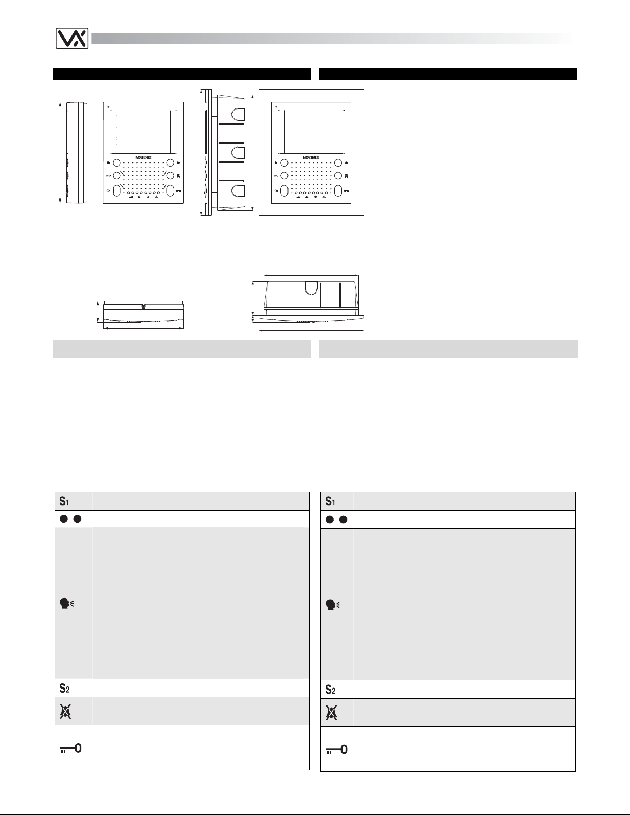
FOR TRADITIONAL VIDEO SYSTEMS USING COAX VIDEO SIGNAL
OR BALANCED VIDEO SIGNAL ART.SL5418
Hands free video monitor using 3.5” full colour active matrix LCD monitor
for traditional (using Art.890/890N or Art.4838 or Art.VR4KAM) video door
entry systems using composite video (coax cable) or balanced video (two
wires V1, V2) to bring the video signal. It requires an additional wire for
12Vdc power supply, in addition to the wires required from 3000 series
videophones for the same systems.
Are available “door open” , “answer/camera recall”, “privacy on/off” buttons
plus 3 service buttons. 4 LED’s give visual signalling relative to the videophone operation. Controls: loudspeaker volume, call tone volume, brightness and hue. Programmable number of rings, privacy duration, door
opening time and video mode. Input for electronic call tone.
The Art.SL5418 is for surface mount but combined with the Art.5981N become for flush mount.
PER SISTEMI VIDEO TRADIZIONALI CON SEGNALE VIDEO
COASSIALE O BILANCIATO ART.SL5418
Videocitofono viva-voce a colori con monitor LCD TFT da 3,5” per sistemi
videocitofonici videx tradizionali (unità di controllo Art.890/890N o Art.4838
o Art.VR4KAM) dove il segnale video è composito (cavo coassiale) o bilanciato (2 fili V1, V2). Rispetto ai videocitofoni serie 3000 per gli stessi
sistemi richiede un filo addizionale per l’alimentazione 12Vdc. Sono presenti i pulsanti: “apri-porta”, “risposta/auto-accensione”, “privacy on/off” più
3 pulsanti di servizio. 4 LED forniscono informazioni circa il funzionamento
del videocitofono. Regolazioni: volume altoparlante, volume del tono di
chiamata, luminosità e saturazione.
Numero di squilli, durata privacy, tempo d’apertura porta e modo video
programmabili. Ingresso per chiamata tramite nota elettronica.
L’Art.SL5418 è per il montaggio da superficie, ma può essere combinato
con l’Art.5981N per il montaggio da incasso.
Push buttons
When pressed, shorts terminal 12 (S1) to ground (max 24Vdc
200mA).
Second camera recall button for two entrances systems.
- Pressing this button during an incoming call will open the
speech in duplex mode allowing free speech with the
caller in both directions (LED “2” next to this button will
illuminate).
- If operated when system is in standby (no Call) camera
recall will be activated and the LED 2 will switch on.
- During a call, pressing this button momentarily will end
the call, LED 2 next to the button will switch off). The
system will automatically switch off when the conversation time expires.
- Pressing and holding the button for more than 2 seconds
will switch the videophone into SIMPLEX speech mode.
Press and hold the button to speak to the caller (LED 2
will flash rapidly), release the button to listen (LED 2 will
flash slowly). If the button is not pressed for 10 seconds
the system will switch off. The videophone will revert to
duplex speech when another call is made.
When pressed, shorts terminal 13 (S2) to ground (max 24Vdc
200mA).
Enables / Disables the privacy service. When privacy is enabled calls will not be received. The LED 3 will illuminate when
the privacy service is enabled.
During a call, operation of this button will release the door
from which the call is coming from. This will be confirmed by
an acoustic signal (if the speech is enabled) for the duration
of the “door open time”. If terminal 19 is connected, the “door
open” LED 4 next to the button will also illuminate.
Pulsanti
Fino a quando resta premuto chiude il morsetto 12 (S1) verso
massa (max 24Vdc 200mA).
Secondo pulsante di auto-accensione per sistemi a 2 ingressi.
- Alla ricezione della chiamata, abilita l’inizio conversazione.Il relativo LED 2 si accende.
- Ad impianto spento, premere il pulsante per eseguire
l’auto-accesione. Il LED 2 si accende.
- Ad impianto acceso, consente lo spegnimento manuale
(rapida pressione del tasto). In ogni caso lo spegnimento
è automatico (il LED 2 si spegne) allo scadere del tempo
di conversazione.
- Premendo il pulsante per più di 2 secondi, il videocitofono passa nel modo trasmissione ad una via: per parlare
con l’esterno occorre tenere premuto il pulsante (il LED
2 lampeggia rapidamente), mentre per ascoltare il visitatore occorre lasciare il pulsante (il LED 2 lampeggia lentamente). Trascorsi 10 secondi, senza premere nuovamente il pulsante, il sistema si spegne. Il videocitofono
torna al funzionamento normale alla successiva accensione.
Fino a quando resta premuto chiude il morsetto 13 (S2) verso
massa (max 24Vdc 200mA).
Attiva/Disattiva il servizio “privacy”. Con il servizio attivo il relativo LED è accesso e le chiamate entranti vengono ignorate.
A sistema acceso, apre la porta. L’apertura è indicata da un
segnale acustico (se la fonia è attiva) per la durata del tempo
d’apertura porta. Se il relativo filo è stato opportunamente
collegato, il LED 4 “door open” resterà acceso fino a quando
la porta resta aperta.
Art.SL5418
Art.SL5418+
A
rt.5981N
Page 2
31
Controls
For each of the 4 available controls, there are two buttons to adjust: press
the left button to decrease or the right button to increase.
Loudspeaker volume control
Call tone volume control
Brightness control
Hue control
Settings
Setup is carried out using the push buttons on the front of the unit and the
dip-switches located on the rear of the unit. There is a system setup to set
the used system and to select either coaxial or balanced video input and a
user setup that include door open time, privacy time, melody and the
number of rings.
Regolazioni
Ciascuna delle 4 regolazioni possibili viene effettuata tramite i relativi 2
pulsanti: premere il pulsante di destra per aumentare o quello di sinistra
per diminuire la regolazione.
Regolazione volume altoparlante
Regolazione volume della nota di chiamata
Regolazione luminosità
Regolazione saturazione colore
Impostazioni
Il videocitofono viene configurato tramite i pulsanti e i dip-switch accessibili nella parte posteriore. C’è un setup di sistema dove si imposta il sistema
in uso e la modalità video (coassiale o segnale video bilanciato) ed un
setup utente per parametri quali il tempo d’apertura serratura, la durata
della funzione privacy, la suoneria ed il numero di squilli.
System setup Setup di sistema
Usual this setup is carried out once and includes the video mode and the
system kind.
Questo setup viene di norma eseguito una volta sola e comprende il modo
video e il tipo di sistema.
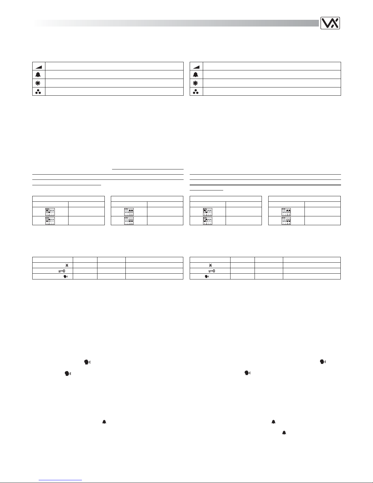
Video Mode
The video mode setup is carried out by the 4 way Dip-Switch accessible
from the rear side of the videophone. Switches 3 and 4 adjust the video
signal impedance. when using more than one videomonitor in parallel
(without a video splitter) put both switches in the OFF position on all but
the last videomonitor (end of line).
Modo Video
La modalità video viene impostata tramite il Dip-Switch a 4 vie accessibile
dalla parte posteriore del blocco superiore del videocitofono.
Gli switch 3 e 4 servono ad adattare l’impedenza del segnale video; in
caso di più videocitofoni collegati in parallelo, devono essere impostati
entrambi ad OFF per tutti i videocitofoni ad eccezione dell’ultimo in ordine
di collegamento.
Video Mode
Switches 1,2 Mode
Coax
Balanced
75 Ohm Video Termination
Switches 3,4 Termination
Enabled
Disabled
Modo Video
Switch 1,2 Modo
Coassiale
Bilanciato
Terminazione video 75 Ohm
Switch 3,4 Terminazione
Abilitata
Disabilitata
System kind Tipo Sistema
The system is set by keeping pressed a specific button of the videophone
while connecting the videophone to the connection board. Release the
button when the videophone confirms the setup by a visual signal.
Button LED Nr.Flashes System
Privacy button Privacy 1 890/890N
Key button Speak 2 VX2000
Speak button Speak 1 4838+Reset
The 890/890N is for use in any system where is used the control unit
Art.890/890N.
The VX2000 is for use in VX2000 digital systems
The 4838 is for use in systems using Art.4838 or Art.VR4KAM
speaker units. The selection of this mode also restores to factory
preset the number of rings, the privacy duration, the door opening
time and the melody.
Il tipo di sistema viene impostato tenendo premuto un pulsante specifico
mentre si collega il videocitofono alla scheda di connessione. Rilasciare il
pulsante quando il videocitofono conferma l’impostazione con un segnale
visivo.
Pulsante LED Lampeggi Sistema
Privacy Privacy 1 890/890N
Chiave Speak 2 VX2000
Parla Speak 1 4838+Reset
Il tipo 890/890N è per qualsiasi sistema operante tramite centrale di
controllo Art.890/890N.
Il tipo VX2000 è per l’utilizzo in sistemi digitali VX2000;
Il tipo 4838 è per l’utilizzo in sistemi con portieri elettrici Art.4838 o
Art.VR4KAM. La selezione di questo modo ripristina ai valori di fabbrica le programmazioni per il numero di squilli, la durata della privacy, il tempo d’apertura porta e la suoneria.
User setup Setup Utente
The user setup concerns the number of rings, the melody, the privacy duration and the door opening time. The factory presets are: 6 rings, melody
1, unlimited privacy duration and 1 second door opening time.
Questo setup riguarda il numero di squilli, la suoneria, la durata della privacy ed il tempo d’apertura porta. I valori impostati di fabbrica sono: 6
squilli, suoneria 1, durata privacy illimitata e tempo d’apertura posta 1 secondo.
Number of Rings Programming (factory preset = 6 rings - max 9)
Press and hold the “
” button (for approx 10 seconds) until the unit
emits a beep and the relevant LED switches on.
Press the “
” button as many times as the number of rings required
minus 1 (i.e. for 6 rings press 5 times, 0 times for 1 ring )
Once the number of rings required has been reached, wait 5 seconds
for the exit beep.
The new value is now stored.
Programmare il numero di squilli (6 squilli di fabbrica – max 9)
Premere e tenere premuto (10 secondi circa) il pulsante “
” fino a
quando il relativo LED si accende e l’unità emette un bip.
Premere il pulsante “
” per un numero di volte pari al numero di
squilli desiderato meno 1 (Es. per 6 squilli premere 5 volte, per uno
squillo attendere l’uscita senza premere).
Selezionato il numero di squilli desiderato, attendere circa 5 secondi
per il bip di uscita e lo spegnimento del LED.
Il nuovo valore è memorizzato.
Melodies Programming (factory preset melody 1)
Press and hold one of the two buttons (for approx 10 seconds) for the
call tone volume adjustment “
” until the unit plays the current stored
melody and emits a beep.
Press the melody button again (left or right) to listen to the available
melodies (maximum 9).
When the chosen melody has been re ached, do not press any but-
tons wait 5 seconds for the exit beep.
The new melody is now stored.
Per programmare la suoneria (di fabbrica melodia 1)
Premere e tenere premu to (10 secondi circa) uno dei pulsanti di re-
golazione del volume di chiamata “
” fino a quando l’unità riproduce
la suoneria correntemente programmata ed emette un bip.
Premere nuovamente uno dei p ulsanti “
” per ascoltare le suonerie
disponibili (max 9).
Selezionata la suoneria desiderata, attendere circ a 5 secondi senza
compiere alcuna operazione fino al bip di uscita.
L’impostazione è memorizzata.
Page 3
32
Privacy duration time (factory preset unlimited duration)
Press and hold (for approx 10 seconds) the “
” button until the rele-
vant LED illuminates and the unit beeps.
Each time the “
” button is pressed, it will increase (starting from 0)
the privacy duration by 15 minutes, press until the required duration
has been reached, when reached, wait 5 seconds the exit beep and
the LED turning OFF.
The new time will be stored.
To set the privacy with no time out (privacy enabled or disabled by pressing the “
” button), don't press any buttons once in privacy programming
mode and wait 5 seconds for the beep and LED to go off.
Per programmare la durata della “privacy” (di fabbrica infinito)
Premere e tenere premuto (10 secondi circa) il pulsante “
” fino a
quando il relativo LED si accende e l’unità emette un bip.
Ogni pressione del tasto “
” incrementa (partendo da 0) la durata del
servizio privacy di 1/4 d’ora: premere fino a raggiungere la durata
desiderata (max 80 volte = 20 ore). Impostato il valore , attendere
circa 5 secondi il bip di uscita e lo spegnimento del LED
Il nuovo valore è memorizzato.
Per impostare la durata illimitata (servizio attivato e disattivato tramite il
pulsante“
”), entrare in programmazione eseguendo il primo passo ed
attendere l’uscita senza premere nulla.
Door Opening Time Programming (factory preset 1 second)
Press and hold the “
” button (for approx 10 seconds) until the unit
emits a beep.
Press the “
” button for the number of seconds required minus 1
(i.e. for 6 seconds press 5 times up to a maximum of 255 seconds).
Once the required door open time has been reached, wait 5 seconds
for the exit beep.
The new value is now stored.
Programmazione del tempo d’apertura porta (di fabbrica = 1s)
Premere e tenere premuto per circa 10 secondi il pulsante “
” fino
a che il videocitofono non emette un bip;
Premere il pulsante “
” tante volte quant’è il numero di secondi che
si vuole impostare meno 1 (Es.6 secondi = 5 volte max 255 secondi);
Raggiunto il valore desiderato, attendere 5 secondi fino all’emissione
di un bip;
Il nuovo tempo d’apertura porta è memorizzato.
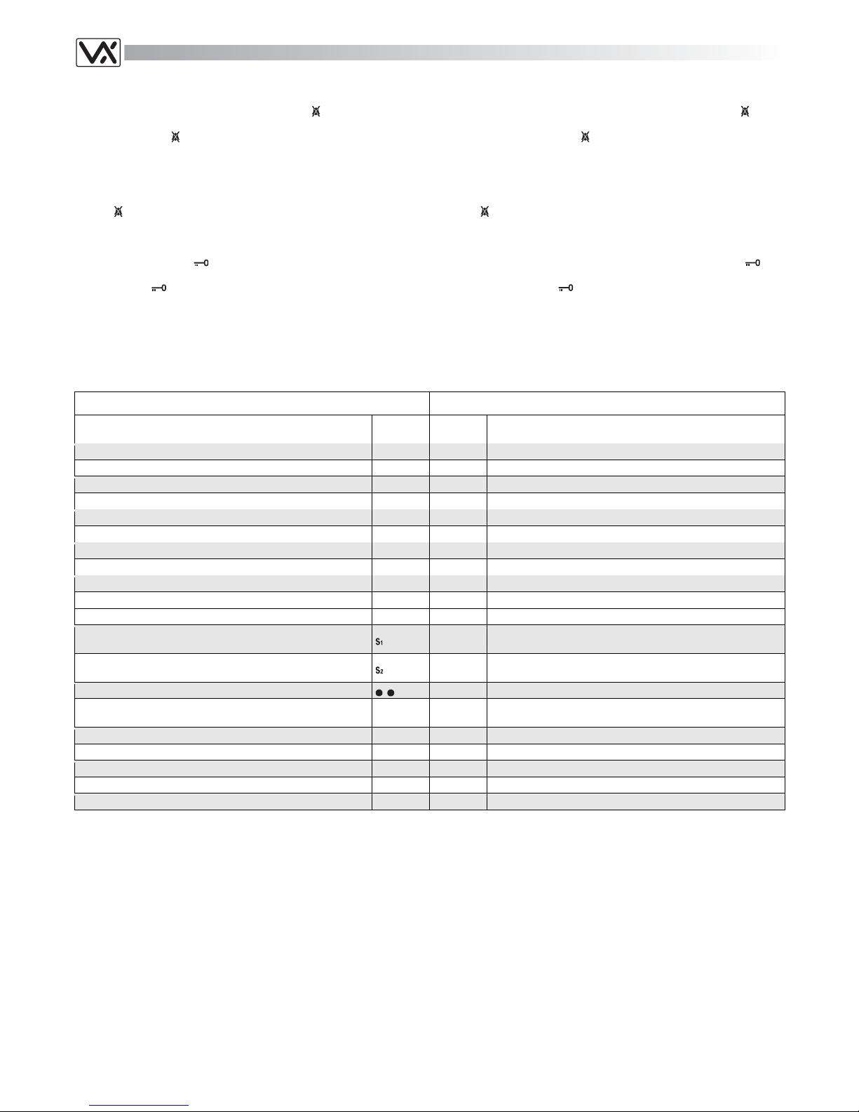
Terminals and relevant signals
The table that follow shows the signals available on the terminals (from 1
to 20) of the PCB supplied with the videomonitor.
Morsetti e relativi segnali
La tabella che segue mostra i segnali presenti sui morsetti della scheda di
connessione (1..20), inclusa nel videocitofono.
ART.SL5418 SIGNALS ON TERMINALS ART.SL5418 SEGNALI MORSETTIERA
Signal Description
Segnale
Signal
Morsetto
Terminal
Descrizione Segnale
+20V power input
+20V 1 Ingresso +20V
+20V power input
+20V 2 Ingresso +20V
Ground
GND 3 Massa
Ground
GND 4 Massa
Coax = V input, Balanced video = V2 input
V2/V 5 Coax = Ingresso V, Video Bilanciato = ingresso V2
Balanced video signal V1 input
V1 6 Ingresso segnale video bilanciato V1
Speech line output from handset’s microphone
3 7 Uscita linea fonica dal microfono della cornetta
Camera recall signal output
T 8 Uscita segnale di auto-accensione
Local bell input (active low)
LB 9 Ingresso per chiamata di piano (attivo basso)
Door open signal output
5 10 Uscita comando apri-porta
12Vdc power supply input auxiliary LED
LDA 11 Ingresso di alimentazione 12Vdc per LED ausiliario
Service button: link the terminal to ground until the button remain pressed (max 24Vdc 200mA).
12
Pulsante di servizio: chiude verso massa fino a quando resta
premuto (max 24Vdc 200mA).
Service button: link the terminal to ground until the button remain pressed (max 24Vdc 200mA).
13
Pulsante di servizio: chiude verso massa fino a quando resta
premuto (max 24Vdc 200mA).
Second camera recall button for two entrances systems.
14 Secondo pulsante di auto-accensione per sistemi a 2 ingressi.
+12V output to supply the video distributor Art.894/894N (coaxial video signal mode)
+VD 15
+12Vdc per alimentare il distributore video Art.894/894N in
modo video coassiale
Speech line input toward the handset’s loudspeaker
4 16 Ingresso fonia verso l’altoparlante della cornetta
+12Vdc stabilized output
12VO 17 Uscita stabilizzata +12Vdc
+12Vdc input
12VI 18 Ingresso di alimentazione +12Vdc
+12Vdc door open / auxiliary LED
LD 19 Ingresso di alimentazione +12Vdc LED porta aperta / ausiliare
Call tone input
C 20 Ingresso nota di chiamata
Table 11
Tabella 11
Technical Specification Specifiche Tecniche
Voltages
Videophone 20Vdc (+2-5V)
12Vdc (+1-4V)
Power Consumption Stand-by Operating
20Vdc 0mA 250mA
12Vdc 20mA 50mA
Tensioni di alimentazione
Videocitofono 20Vdc (+2-5V)
12Vdc (+1-4V)
Assorbimento A riposo In funzione
20Vdc 0mA 250mA
12Vdc 20mA 50mA
Page 4

33
ART.SL5418 WALL MOUNTING ART.SL5418 FISSAGGIO A PARETE
Fig.1
Fig.3 Fig.4
Fig.2
135cm
C
B
A
A
G
A
D
D
E
F
B
H
J
C
To install Art.SL5478 it is necessary to open it. Follow picture n.4:
turn screw “G”, pull cover “D” and lift it up (or push it forward if the
videomonitor is in horizontal position), then disconnect plug “E”
(Fig.3) from plug “F” on the connection board housed on the bottom
“A”.
Put the bottom “A” against the w all at 135cm from the finished floor
(Fig.1). All cables must be fed through hole “H” (Fig.2).
Leaving approximately 135cm from the finished floor, fit the bottom
“A” against the wall and mark the fixing holes considering that the
cables must fed through the opening “H” (Fig.2)
Make the holes, and fix bottom “A” on the wall using the two wall
plugs “B” and the two screws “C” as shown in figure 2.
Make all connections as per provided diagram.
As shown in figure 3, move cover “D ” close to bottom “A”, connect
plug “E” to plug “F” on the connection board then proceed with the
next step.
Hook cover “D” to bottom “A ” by using the two clips “J” (Fig.2) as
shown in figure 4 then push down cover “D” towards bottom “A”.
Then proceed with system testing.
When finished the testing, fix cover “D” at the bottom “A ” using the
screw“G” (Fig.4).
Per installare il videocitofono Art.SL5478 è necessario aprirlo: facen-
do riferimento alla figura 4, svitare la vite “G”, tirare a se il coperchio
“D” quindi spingerlo verso l’alto (o in avanti se si effettua l’operazione
tenendo il videocitofono in orizzontale) e scollegare il connettore maschio “E” (Fig.3) dal connettore femmina “F” (Fig.3) della scheda di
connessione alloggiata sulla base “A”.
Appoggiare a parete la base “A” ad una altezza di circa 135cm
(Fig.1) dal pavimento finito e prendere i riferimenti per i fori di fissaggio, tenendo presente che i conduttori devono passare attraverso la
fessura “H” (Fig.2).
Realizzare i fori e fissare a parete la base “A” con l’ausilio dei 2 tas-
selli ad espansione “B” e delle due viti “C” come mostrato in figura 2.
Effettuare le connessioni come da schema fornito a corredo.
Come mostrato in figura 3, avvicinare il coperchio “D” alla base “A”,
inserire il connettore “E” nel connettore “F” (sostenere con le mani il
peso del coperchio) e proseguire con il passo successivo.
Con l’ausilio degli incastri “J” (Fig.2) agganciare il coperchio “D” alla
base “A” come mostrato in figura 4 quindi spingere la parte inferiore
del coperchio “D” verso la base “A” e procedere al collaudo del sistema.
Terminato il collaudo del sistema, assicurare il coperchio “D” alla ba-
se “A” con l’ausilio della vite “G” (Fig.4).
Page 5

34
ART.SL5418-5418 FLUSH MOUNT USING ART.5981N ART.SL5418-5418 MONTAGGIO DA INCASSO CON ART.5981N
d
d
g
a
d
g
e
f
b
d
c
l
l
l
l
h
i
o
o
o
o
n
h
a
m
Fig.1 Fig.2 Fig.3
i
h
p
Fig.4 Fig.5 Fig.6
Protect the videophone fixing holes “d” (Fig.1) from dust then embed
the flush back box “a” (Fig.1) into the wall (about 135cm between the
bottom of the box and the floor level as shown on the Figure 1 on
page 33). Observe the direction of the box (see instruction on the
bottom of the box) and take care that the box profile is in line with the
finished wall profile;
Hook the pcb connection board “b” to the flush mounting box “a” as
shown in figure 1 (see pointers) feeding the cables “e” through the
opening “f” then fix the connection board using the screw “c”;
With the connection board “b” fitted, connect the wires to terminal “g”
(Fig.1) as shown in the diagram provided;
Arrange the videophone “h” fixing to it the two brackets “i” using the 4
screws “l” as shown in figure 2. If the videomonitor is not a slim
line model, first arrange the brackets by cutting their upper and lower sides as shown in figure 5 then, as described above, fix the brackets to the videomonitor as shown in figure 6;
As shown on figure 3, move the videophone “h” close to the back
box, connect the plug “m” on the ribbon cable from the videophone to
the plug “n” on the pcb connection board then fix the videophone “h”
to the back box “a” using the four screws “o”;
• As shown on figure 4, align the frame “p” with the brackets “i” then
push it toward the wall until the frame is hooked.
Proteggere opportunamente i fori di fissaggio “d” ( Fig.1) quindi mura-
re la scatola da incasso “a” lasciando circa 135cm tra la parte inferiore della scatola ed il pavimento (Fig.1 pag.33). Fare attenzione al
verso della scatola (vedi le indicazioni sul fondo della stessa) e a che
venga murata a filo muro finito;
Agganciare la scheda di connessione “ b” alla scatola da incasso “a”
come mostrato in figura 1 (vedi verso delle frecce) facendo passare i
fili “e” attraverso l’apertura “f” quindi fissare la scheda alla scatola
tramite la vite “c”;
Una volta fissata la scheda di connessione “b”, collegare i fili ai mor-
setti “g” (fig.1) in accordo con quanto indicato nello schema di connessione fornito a corredo;
Preparare il videocitofono “h” montando le due staffe “i” utilizzando le
4 viti “l” come mostrato in figura 2. Se il videocitofono da incasso
non è di tipo slim, preparare le staffe tagliando la parte (sia superiore che inferiore) mostrata in figura 5, quindi analogamente a come
sopra descritto fissare le staffe al videocitofono come mostrato in figura 6;
Come mostrato in figura 3, avvicinare il videocitofono “h” alla scatola
da incasso, collegare il connettore “m” del cavo flat che fuoriesce dal
videocitofono al connettore “n” della scheda di connessione quindi
fissare il videocitofono “h” alla scatola da incasso “a” utilizzando le 1
viti “o”;
Come mostrato in figura 4, allineare la cornice “p” con le staffe “i” e
premere la stessa verso il muro fino all’aggancio.
RICORDA!
Il taglio delle
staffe non è
richiesto per i
videocitofoni
della linea
SLIM
REMEMBER!
For slim line
videomonitors
the cut of the
brackets is
not required
Page 6

Page 7

Page 8

 Loading...