

Page 1
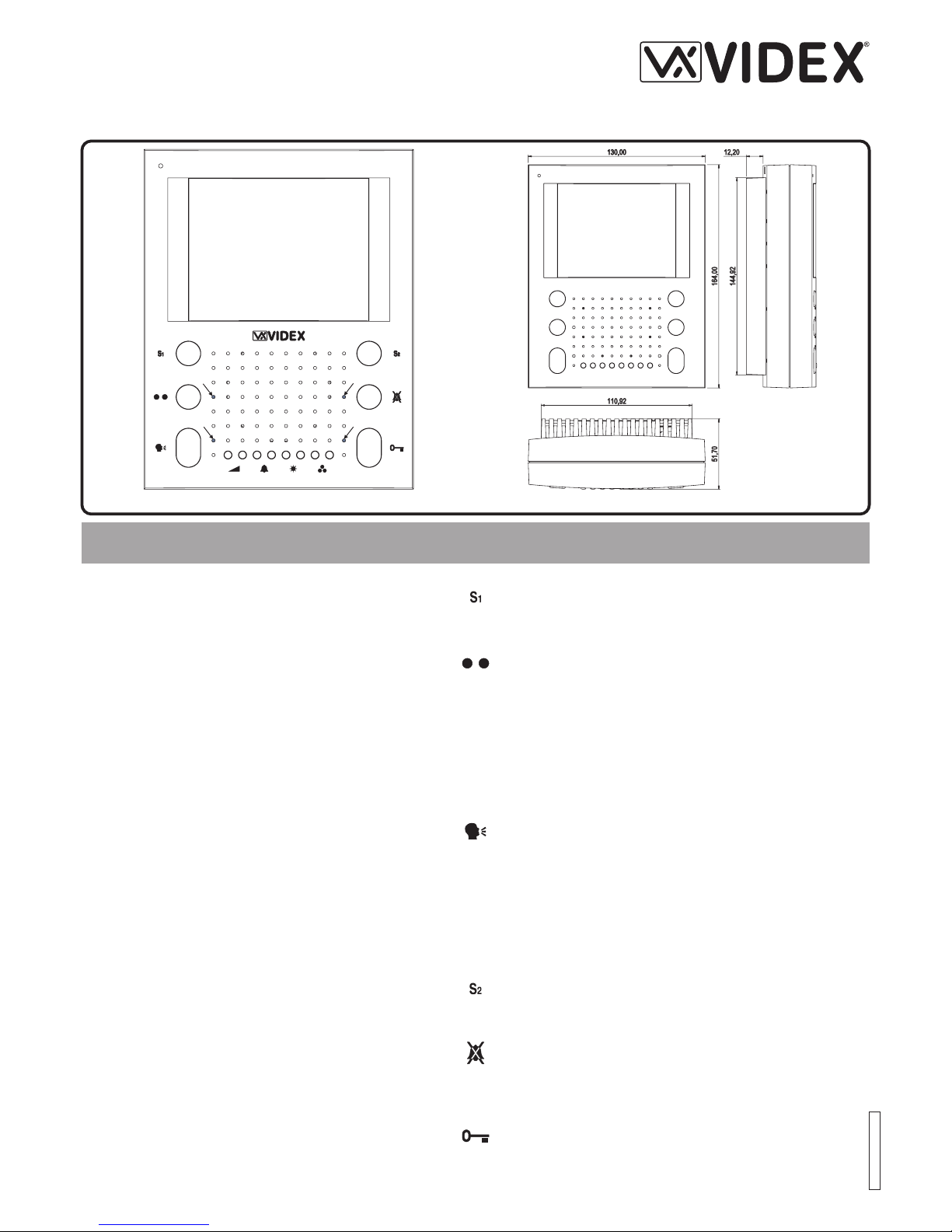
PULSANTI PUSH BUTTONS
Pulsante di Servizio
Fino a quando resta premuto chiude il morsetto “S1” verso il
morsetto “GND” (massa).
Service push button
When pressed, shorts terminal “S1” to terminal “GND” (ground).
Pulsante Relè
Ad ogni pressione commuta in maniera stabile il morsetto
“COM2” verso il morsetto “NO2” o “NC2”. Quando “COM2” è su
“NO2”, il LED relativo al pulsante è acceso.
Latch relay button
Each time this button is operated it will latch “COM2” to “NO2 or
“NC2” alternately (Toggle action) and switch the relevant LED
ON.
Pulsante risposta/autoaccensione/spegnimento/tx-rx 1 via
trasmissione ad una via
B
B
B
B
Alla ricezione della chiamata, abilita l’inizio conversazione. Il
relativo LED si accende.
Ad impianto spento, premere il pulsante per l’auto-accesione. Il
LED si accende.
Ad impianto acceso, consente lo spegnimento manuale (rapida
pressione del tasto). In ogni caso lo spegnimento è automatico
(il LED si spegne).
Premendo il pulsante per più di 3 secondi, il videocitofono
passa nel modo : per parlare con
l’esterno occorre tenere premuto il pulsante (il LED lampeggia
rapidamente), mentre per ascoltare il visitatore occorre lasciare
il pulsante (il LED lampeggia lentamente). Il videocitofono torna
al funzionamento normale alla successiva accensione.
Answer/Camera Recall/Switch off/1 way tx-rx button
B
B
B
B
On an incoming call, operation of this button allows the user to
answer and converse with the visitor. The relevant LED will
switch ON.
If operated when system is in standby (no Call) camera recall
will be activated and the relevant LED will switch on.
With the system switched on (monitor on), momentary operation of the button will switch the system into standby. The
system will automatically switch to standby after a time delay if
the button is not operated. The relevant LED will switch off.
By operating and holding the button for more than 3 seconds,
the videophone will enter the SIMPLEX speech mode. Press
and holding the button will allow speech to the outside door
panel (the relevant LED will flash rapidly), to listen to the visitor
at the outside door panel release the button (the relevant LED
will flash slowly). Thevideophone will revert to normal operation
when another call is made from the outside door panel.
Pulsante di Servizio
Fino a quando resta premuto chiude il morsetto “S2” verso il
morsetto “GND” (massa).
Service push button
When pressed, shorts terminal “S2” to Terminal “GND” (ground)
Pulsante “Privacy”
Attiva/Disattiva il servizio “privacy”. Con il servizio attivo il
relativo LED è accesso e le chiamate entranti vengono ignorate.
Privacy on/off button
Enables / Disables the privacy service. When privacy is enabled
the relevant LED is switched on and no incoming calls will be
received.
Pulsante “Apri-Porta”
A sistema acceso, apre la porta. L’apertura è indicata
dall’accensione del relativo LED e da un segnale acustico (se la
fonia è attiva) per la durata del tempo d’apertura porta.
Door open push button
When the system is switched on, operation of this button will
activate the “door open” relay (NO1, NC1, COM1). This will
switch on the relevant LED and be confirmed by an acoustic
signal for the duration of the “door opening time”
Fig.1
AB
1
3
4
2
Art.5418
Istruzioni di Istallazione
Installation Instructions
ECLIPSE HANDS FREE VIDEOPHONE
VIDEOCITOFONO VIVA-VOCE ECLIPSE
66250470.cdr - 23/11/2006
Page 2
CONFIGURAZIONE VIDEOCITOFONO VIDEOPHONE SETUP
La configurazione del videocitofono consiste
nell’impostazione della modalità video (coassiale o segnale
video bilanciato) e di alcuni parametri quali il tempo d’apertura
serratura, la durata della funzione privacy ed il numero di
squilli.
La modalità video viene impostata tramite il Dip-Switch a 3 vie
accessibile dalla parte posteriore delvideocitofono.
ON OFF ON Segnale video coassiale
OFF ON ON Segnalevideo bilanciato
I valori impostati di fabbrica sono8 per gli squilli, 4 secondi per
il tempo d’apertura porta e 60 minuti per la durata della
privacy. Premere contemporaneamente il primo (tasto sinistro
della regolazione volume altoparlante) e l’ultimo (tasto destro
della regolazione colore) dei tasti di regolazione per entrare in
programmazione, il LED 1 (Fig.1A) inizia a lampeggiare ad
indicare il “ ”. Trascorsi 20 secondi di
inattività dall’entrata in programmazione o dall’ultima operazione di programmazione, il videocitofono esce automaticamente da questa modalità.
Una volta entrati nel modo programmazione, premere e
tenere premuto il pulsante “ ”, il LED 1 smette di lampeggiare ed inizia a lampeggiare ad indicare il
numero di secondi che si stanno impostando: al raggiungimento del valore desiderato (es. 5 lampeggi = 5 secondi)
rilasciare il pulsante
IMPOSTAZIONE MODALITA’VIDEO
Switches Modo Video
12 3
PROGRAMMAZIONE Nr.SQUILLI, TEMPO APERTURA
PORTA E DURATAPRIVACY
modo programmazione
Per programmare il tempo d’aperturaporta
il LED 4 (Fig.1A)
“ ”. Il LED 1 torna a lampeggiare
indicando la possibilità di eseguirealtre programmazioni.
Una volta entrati nel modo programmazione, premere e
tenere premuto il tasto “ ”, il LED 1 smette di lampeggiare ed
inizia a lampeggiare il LED 3 ad indicare la durata che si sta
impostando: al raggiungimento del valore desiderato
(ciascun lampeggio aumenta il tempo di 15 minuti quindi 6
lampeggi corrispondono a 1,5 ore) rilasciare il pulsante “ ”. Il
LED 1 torna a lampeggiare indicando la possibilità di
eseguire altre programmazioni.
Una volta entrati nel modo programmazione, premere e
tenere premuto il tasto “ ”, il LED 1 smettedi lampeggiare ed
inizia a lampeggiare il LED 2 ad indicare il numero di squilli
che si sta impostando: al raggiungimento del valore desiderato (Es. 6 lampeggi = 6 squilli) rilasciare il pulsante “ ”. Il
LED 1 torna a lampeggiare indicando la possibilità di
eseguire altre programmazioni.
Per programmare la durata dellafunzione “privacy”
Per programmare il numero disquilli
The videophone setup allows the correct mode of operation to
be selected, this includes coaxial or balanced video, door
opening time, privacy time andthe number of rings.
The video mode setup is carried out by the 3 way Dip-Switch
accessible from the rear sideof the videophone.
ON OFF ON Coaxial video signal
OFF ON ON Balancedvideo signal
The preset values are 4 seconds for door opening time, 60
minutes for the privacy durationand 8 for the number of rings.
To alter the above preset values the videophone must be in
programme mode. This is achieved by operating the two
following buttons at the same time (left button of the volume
control and the right button of the colour intensity control) see
Fig.1A 8 small buttons towards thebottom of the face plate (far
left button and far right button together). When the programming mode is entered LED 1 (Fig.1A) starts flashing. This will
automatically reset after 20 secondsof idle time.
After entering the programme mode press and hold the
button, LED 1 will stop flashing and LED 4 (Fig.1A) will start
to flash for the number of seconds required (i.e. 5 flashes = 5
seconds) release the
button. LED 1 will start flashing to signal that other
programming operations can be performed.
VIDEO MODE SETUP
Switches Video Mode
12 3
DOOR OPENING TIME, PRIVACY DURATION AND
NUMBER OF RINGS PROGRAMMING
Door opening time
“”
once the time value has been reached
“”
When in the programme mode press and hold the “ ” button,
LED 1 will stop flashing and LED 3 (Fig.1A) will start to flash
and show the time value (each flash =15 minutes i.e. 6
flashes = 1.5 hour) once the time value has been reached
release the “ ” button. LED 1 will start flashing to signal that
other programming operations can beperformed.
When in the programming mode press and hold the “ ”
button, LED 1 will stop flashing and LED 2 (Fig.1A) will start
to flash showing the number of rings (each flash = 1 ring i.e. 6
flashes = 6 rings) once the value of rings has been reached
release the “ ” button. LED 1 will start flashing to signal that
other programming operations can beperformed.
Privacy duration time
Number of rings
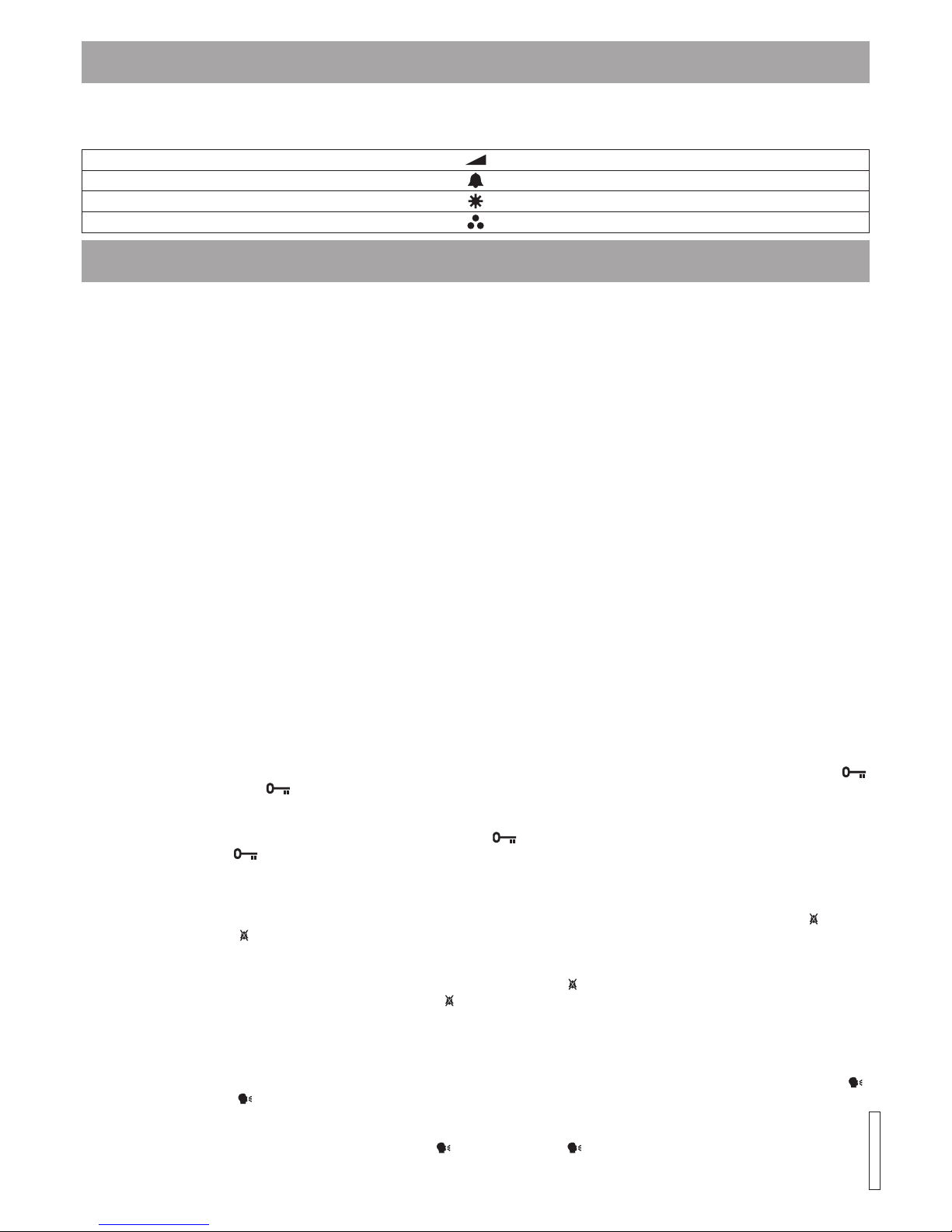
REGOLAZIONI CONTROLS
Regolazione Volume Altoparlante Loudspeaker volume control
Regolazione Volume Tono di Chiamata Call tone volume control
Regolazione Luminosità Brightness control
Regolazione Colore Color intensity control
Ciascuna delle 4 regolazioni possibili viene effettuata tramite i
relativi 2 pulsanti: premere il pulsante di destra per aumentare o
quello di sinistra per diminuire la regolazione.
Each of the4 possible adjustments is carried out by operation of the
two buttons associated with that group.Operationofthe right button
will increase and operation of the left button will decrease.
66250470.cdr - 01/12/2006
Page 3

7
5
,
0
0
104,00
3
5
,
0
0
80,00
+20V
NC2
COM2
NO2
S1
T
S2
V1
GND
V2/V
GND
LD
C
+12
3
+VD
4
NO1
COM1
NC1
SEGNALI SCHEDA DI CONNESSIONE PCB CONNECTION BOARD
SEGNALI SCHEDA DI CONNESSIONE ART.5980 PCB CONNECTION BOARD ART.5980 SIGNALS
Descrizione
Morsetto
Terminal
Description
Ingresso di alimentazione +20V
+20V
+20V power input
Relè pilotato dal pulsante !! contatto normalmente chiuso
NC2
Relay controlled by the !! button normally closed contact
Relè pilotato dal pulsante !! contatto comune
COM2
Relay controlled by the !! button common contact
Relè pilotato dal pulsante !! contatto normalmente aperto
NO2
Relay controlled by the !! button normally open contact
Morsetto pilotato dal pulsante S1, chiude verso GND quando il
pulsante viene premuto
S1
Terminal controlled by the S1 button, close to GND until the button is pressed
Segnale di auto-accensione
T
Camera recall signal output
Morsetto pilotato dal pulsante S2, chiude verso GND quando il
pulsante viene premuto
S2
Terminal controlled by the S1 button, close to GND until the button is pressed
Ingresso segnale video bilanciato V1
V1
Balanced video signal V1 input
Massa
GND
Ground
Ingresso segnale video bilanciato V2 nel modo “SEGNALE VIDEO BILANCIATO”
In balanced video signal mode = Balanced video signal V2 input
Ingresso segnale video V nel modo “SEGNALE VIDEO COASSIALE”
V2/V
In coaxial video signal mode = coaxial video signal V input
Massa segnale video nel modo “SEGNALE VIDEO COASSIALE”
GND
Ground input
Ingresso +12V per led “DOOR OPEN”
LD
+12V input so supply “DOOR OPEN” LED
Ingresso segnale di chiamata
C
Call tone input
Ingresso di alimentazione +12V
+12
+12V power input
Uscita fonia proveniente dal microfono della cornetta
3
Speech line output from handset’s microphone
Uscita +12V per alimentazione distributore video Art.894 (modo
coassiale)
+VD
+12V output to supply the video distributor Art.894 (coaxial video
signal mode)
Ingresso fonia verso l’altoparlante della cornetta
4
Speech line input toward the handset’s loudspeaker
Relè apri-porta – contatto normalmente aperto
NO1
Door open relay normally open contact
Relè apri-porta – contatto comune
COM1
Door open relay common contact
Relè apri-porta – contatto normalmente chiuso
NC1
Door open relay normally closed contact
Fig.2
Art.5980
Istruzioni di Istallazione
Installation Instructions
Mounting Plate & Connection Board
Piastra di fissaggio e Scheda di connessione
Page 4

135cm
n
h
i
l
m
m
m
m
a
a
a
b
c
c
c
f
f
f
f
g
e
d
b
b
b
a
Fig.1 Fig.2
Fig.3 Fig.4
A
B
!
!
!
!
!
!
Cables must be fed through the opening “e” (Fig. 2A) of the
mounting plate “c”, which should be fitted approximately
135cm from finished floor levelas shown inFig 1;
Place the mounting plate “c” against the wall feeding the
wire group “d” through opening “e” of the mounting plate and
mark the fixing holes “a”(Fig. 2A)
Drill the fixing holes “a”, insert the wall plugs “b” then with the
cables threaded through opening “e” fix the mounting plate
“c” to the wall withthe 4 screwsprovided “f” (Fig.2A).
Hook the pcb connection board “g” to the mounting plate
“c”as shown in Fig2B and connect the wires (using the
screwdriver provided) to the terminals as shown in the
diagram provided;
Once the wires are connected, hook the videophone “h” to
the Mounting plate “c” asshown in Fig.3.
Connect the Plug “I” on the ribbon cable from the
videophone to the plug “l” on the PCB connection board
“g”;
Place the videophone “h” against the 4 hooks “m” on the
mounting plate “c” (in line with the 4 openings “n” on the
rear side of the videophone Fig. 4) and push down as
suggested by the pointers in Fig. 3, the videophone will
lock into place;
To remove the videophone, hold it firmly and push the unit in
an upward direction until the videophone “h” unlocks from
the mounting plate “c”.
!
!
VIDEOCITOFONO - ISTRUZIONI DI
MONTAGGIO A PARETE
VIDEOPHONE - WALL MOUNTING
INSTRUCTIONS
!
!
!
!
!
!
Dovendo passare attraverso la fessura “ ” (fig.2A) della
placca di fissaggio a parete, consigliamo di canalizzare i
conduttori in maniera tale da lasciare 135cm circa tra la
parte inferiore della scheda di fissaggio ed il pavimento
finito come mostrato in figura1;
Appoggiare la piastra di fissaggio “ ” alla parete facendo
passare il gruppo di fili “ ” attraverso l’apertura “ ” della
stessa e prendere i riferimenti per i fori di fissaggio “ ”
(fig.2A);
Eseguire i fori “ ”, inserire al loro interno i tasselli ad espansione “ ” e dopo aver fatto passare il gruppo di fili “ ”
attraverso l’apertura “ ” fissare la piastra “ ” alla parete
tramite le viti “ ” fornite acorredo (Fig.2A);
Agganciare la scheda di connessione “ ” alla placca di
fissaggio “ ” come mostrato in figura 2B e procedere alla
connessione dei fili alla morsettiera (in accordo con lo
schema fornito) tramite il giravite(lama lato ataglio) fornito a
corredo;
Collegati i fili, agganciare il videocitofono “ ” alla piastra “ ”
come mostrato in figura 3:
inserire il connettore “ ” del cavo flat che fuoriesce dal
retro del videocitofono nel connettore “ ” della scheda di
connessione (Fig.3),
avvicinare il videocitofono alla placca di fissaggio facendo
corrispondere le aperture “ ” (Fig.4) ai ganci “ ” (Fig.3)
quindi spingere il videocitofono verso il basso fino
all’aggancio come suggerito dalle freccein figura 3.
Per rimuovere il videocitofono, tenendolo saldamente
spingerlo verso l’alto fino allosblocco.
e
c
de
a
a
bd
ec
f
g
c
hc
i
l
nm
!
!
Page 5

Page 6

 Loading...