

Page 1
66250800-EN - V2.0 - 08/04/15
1
5000 Series Eclipse Range
Art.5188 - Installation instructions
Art.5188 Hands free intercom
164,00
74,00
23,50
24,50
1 2 345 6 7 8
ON
SW1
1 2 3 4
ON
SW3
A
B
JP1
2
1
4
3
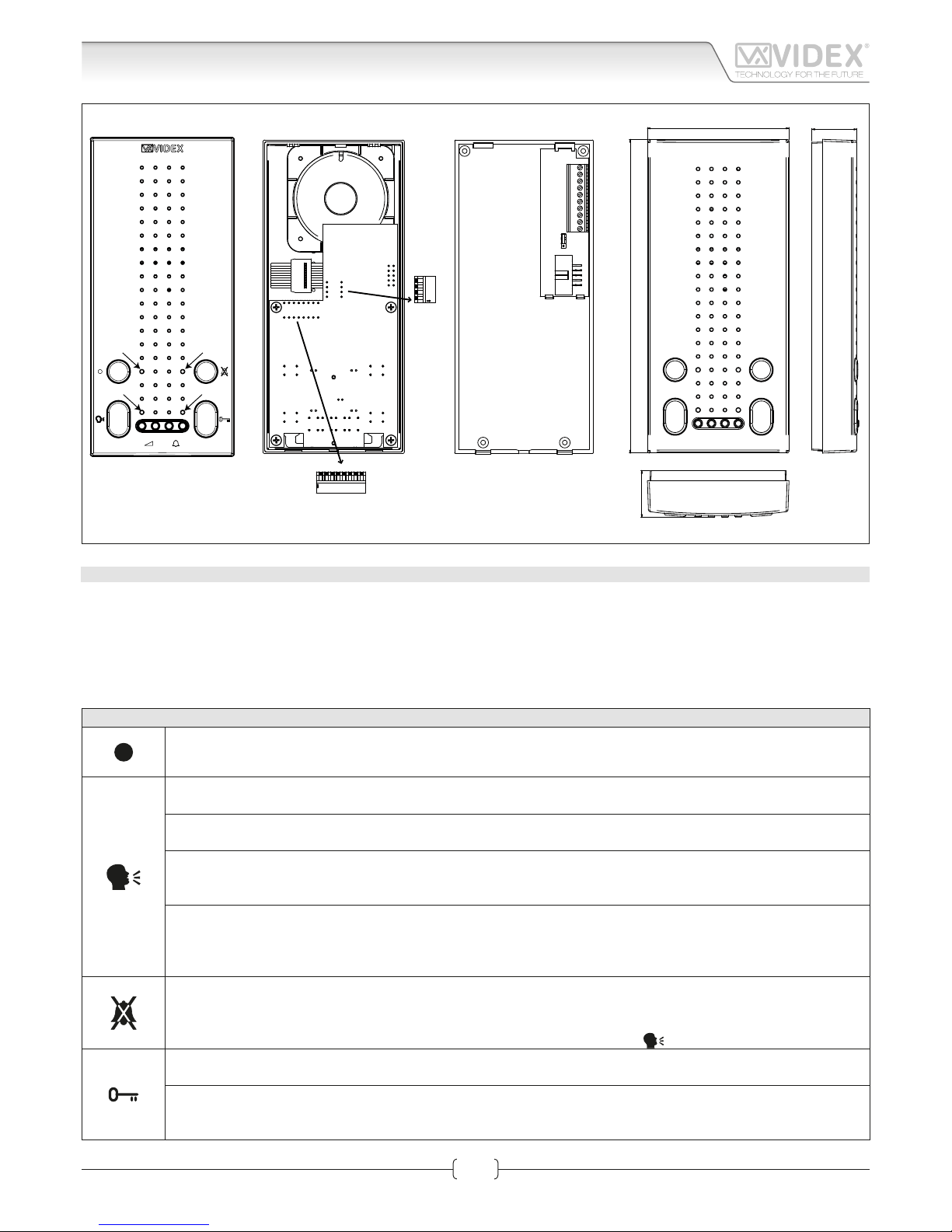
Fig. 1
DESCRIPTION
Voice switched hands free intercom with buttons to control “answer/end conversation/recall/simplex conversation”, “door open/
intercommunicating call”, “privacy on/o” (programmable duration) and “BUS relay control” (Art.2305) button. In addition there
are 4 LED’s* to indicate the status of “answer/end conversation”, “door open/closed”, “privacy on/o” and programming status. Call
tone and loudspeaker volume controls, through assigned buttons, are also incorporated on this model. In addition to programming
required from the VX2300 digital system (address, extension address and intercommunication mode) it is possible to program the
melody, the number of rings and the privacy service duration. Surface wall mount installation.
* The operation of some LED’s and the functions described may require additional cabling.
PUSH BUTTONS, LEDS AND CONTROLS FIG. 1
Bus Relay Button to Activate bus relay board Art.2305.
To activate a bus relay press as many times as the address value of the relay.
Answer button.
On an incoming call, operation of this button allows the user to answer and converse with the visitor. LED 2 will illuminate.
Camera recall push button.
Press as many times as the DEVICE N. of the door station to switch on.
Switch o button.
With the system switched on, momentary operation of the button will switch the video monitor o. The intercom
will also automatically switch o after a time delay if the button is not pressed. LED 2 will switch o.
Simplex button.
Pressing and holding the button for more than 3 seconds will switch the intercom into SIMPLEX speech mode. Press and hold
the button to speak to the caller (LED 2 will ash rapidly), release the button to listen (LED 2 will ash slowly). If the button is
not pressed for 10 seconds the intercom will switch o. The intercom will revert to duplex speech when another call is made.
Privacy ON-OFF push button.
• If the unit is switched on, press and keep pressed this button for more than 3 seconds to enable/disable the service. The relative LED will illuminate when the privacy service is enabled.
• If the unit is switched o, keep this button pressed together with the “speak” button until the privacy LED switches ON.
Intercommunicating call button.
For an intercommunicating call, when the intercom is in stand-by, press as many times as the extension or address value to call.
Door open button.
During a call, operation of this button will activate the “door open” relay (NO1, NC1, COM1). LED 4 will illuminate if
terminal 6 has been connected to a door contact.
Page 2
66250800-EN - V2.0 - 08/04/15
2
5000 Series Eclipse Range
Art.5188 - Installation instructions
PUSH BUTTONS, LEDS AND CONTROLS FIG. 1
LED 1 Programming LED.
LED 2 LED relating to the operation of the answer/switch o/camera recall/simplex button.
LED 3 LED relating to the operation of privacy button.
LED 4
LED relating to the operation of door open button(powered from the connection terminal “2” & GND “1” on the connection board).
Loudspeaker volume control.
Call tone volume control.
PROGRAMMING
The intercom setup consists of the following settings:
• Number of Rings;
• Privacy duration;
• Melody selection;
• Unit address (1..127, switches 1 to 7 of SW1);
• Intercommunication mode (between apartments or within apartment switch 1 of SW3);
• Extension address (1..4, switches 2,3 of SW3);
• Bus Termination (JP1 jumper on connection board);
The programming of the number of rings, melody and privacy duration are carried out through the intercom push buttons , all other settings are carried out on the two dip-switch banks (SW1 and SW3) on the rear side of the video monitor. The BUS termination
depends on the position of JP1 on the connection board.
Except for when programming the number of rings, it is necessary to temporarily remove the power supply from the unit
after making programming changes.
NUMBER OF RINGS, PRIVACY DURATION AND MELODY SELECTION
First of all make a recall to switch on the unit then proceed with the programming operation. To alter the number of rings and select the melody, the intercom must be in program mode. This is achieved by pressing the two following buttons at the same time
(left button of the volume control and the right button of the call tone volume control) see Fig. 1.When the programming mode is
entered LED 1 (Fig. 1) starts ashing. This will automatically reset after 20 seconds of idle time.
NUMBER OF RINGS
• When in the programming mode press and hold the
button, LED 1 will stop ashing and LED 3 (Fig. 1) will start to ash show-
ing the number of rings (each ash = 1 ring i.e. 6 ashes = 6 rings).
• Once the value of rings has been reached release the
button.
• Wait approx 10 seconds for LED 1 to stop ashing to signal that the new value is stored and program mode has exited.
PRIVACY DURATION
• When in the programming mode press and hold the
button, LED 1 will stop ashing and LED 3 (Fig. 1) will start to ash show-
ing the number of times the button is pressed (each ash = 15 minutes i.e. 8 ashes = 2 hours ).
• Once the duration required has been reached release the
button.
• Wait approx 10 seconds for LED 1 to stop ashing to signal that the new value is stored and program mode has exited.
MELODY SELECTION
• When in the programming mode, press left or right call tone volume control buttons
(press the left button to navigate backward or the right button to navigate forward in the melodies selection menù) until the videomonitor plays the selected melody
(during the melody play the LED1 stops ashing).
• Before press again one of the two buttons to select previous (left button) or next (right button) melody, wait for LED1 starts ashing again then press and hold pressed one button until the selected melody is played.
• Once reached the required melody, wait approx 10 seconds for LED 1 to stop ashing to signal that the new value is stored and
program mode has exited.
NOTES
The second melody increases its volume at each ring: rst ring starts at minimum volume level and adjusts up to the maximum
volume level on the last ring. There are 4 volume levels: Rings after this will all play at full volume.
Art.5188 Hands free intercom
Page 3
66250800-EN - V2.0 - 08/04/15
3
5000 Series Eclipse Range
Art.5188 - Installation instructions
Art.5188 Hands free intercom
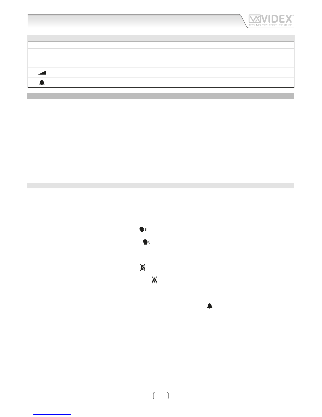
VIDEOPHONE ADDRESS SW1.1..7
SW1
The table below shows how to set the address of the videophone. Considering that ON = 1 and OFF = 0, multiply
each digit for the relevant decimal weight then sum values obtained to get the address: E.g. as highlighted in the
table OFF, ON,OFF, OFF, ON, OFF, ON in binary is equal to 0100101 then multiplying each digit for the relevant
decimal weight you obtain the address that is 37.
SWITCHES STATUS BINARY CODE DECIMAL WEIGHT ADDRESS
7 6 5 4 3 2 1 64 32 16 8 4 2 1
OFF OFF OFF OFF OFF OFF ON 0 0 0 0 0 0 1 1
OFF OFF OFF OFF OFF ON OFF 0 0 0 0 0 1 0 2
OFF OFF OFF OFF OFF ON ON 0 0 0 0 0 1 1 3
OFF OFF OFF OFF ON OFF OFF 0 0 0 0 1 0 0 4
OFF ON OFF OFF ON OFF ON 0 1 0 0 1 0 1 37
ON ON ON ON ON ON ON 1 1 1 1 1 1 1 127
Note: The maximum number of units allowed is 100 but the address of each unit can be a value between 1 and 127.
Set switch 8 to OFF position.
INTERCOMMUNICATION MODE SW3.1
SW3
This switch establishes the intercommunication mode: in OFF position (default) intercommunication is between units
in the same apartment (same addresses but dierent extension); in ON position the intercommunication is between
units in dierent apartments (dierent addresses).
On installations where there are more than one intercom/videophone in the same apartment and intercommunication between dierent apartments is required, only one intercom/videophone may be set with this function (SW3.1=ON, SW3.2=OFF,
SW3.3=OFF). The other intercom/videophones in the apartment must be set for local intercommunication with extension
addresses “2-4” (slaves). From the intercom/videophone set for intercommunication with other apartments it will be not possible to intercommunicate within the apartment but slave extensions 2-4 will be able to intercommunicate with each other.
EXTENSION NO SW.2..3
SW3
If the intercommunication between apartments is enabled (switch 1 of SW3 = ON)
leave these two switches in default position (both to OFF). Otherwise, if the intercommunication is between the same apartment (switch 1 of SW3 = OFF), set the
extension addresses starting always from 1.
Note: Set switch “4“ to OFF position
BUS LINE TERMINATION JP1
The factory preset for this jumper is “A” position: termination enabled. In case of more units (intercoms, videophones or video monitors) in a parallel connection (bus wires are connected to the terminals of the rst unit then from this to the second and so on up
to 4 units max) JP1 must be set to A position only for the last unit in the chain while on all other units must be set to B position (bus
termination disabled). In case of units of dierent type, videophones, video monitor, hands free or standard intercoms etc. remains
xed the rule that the bus termination must be enabled only on the last unit in order of connection.
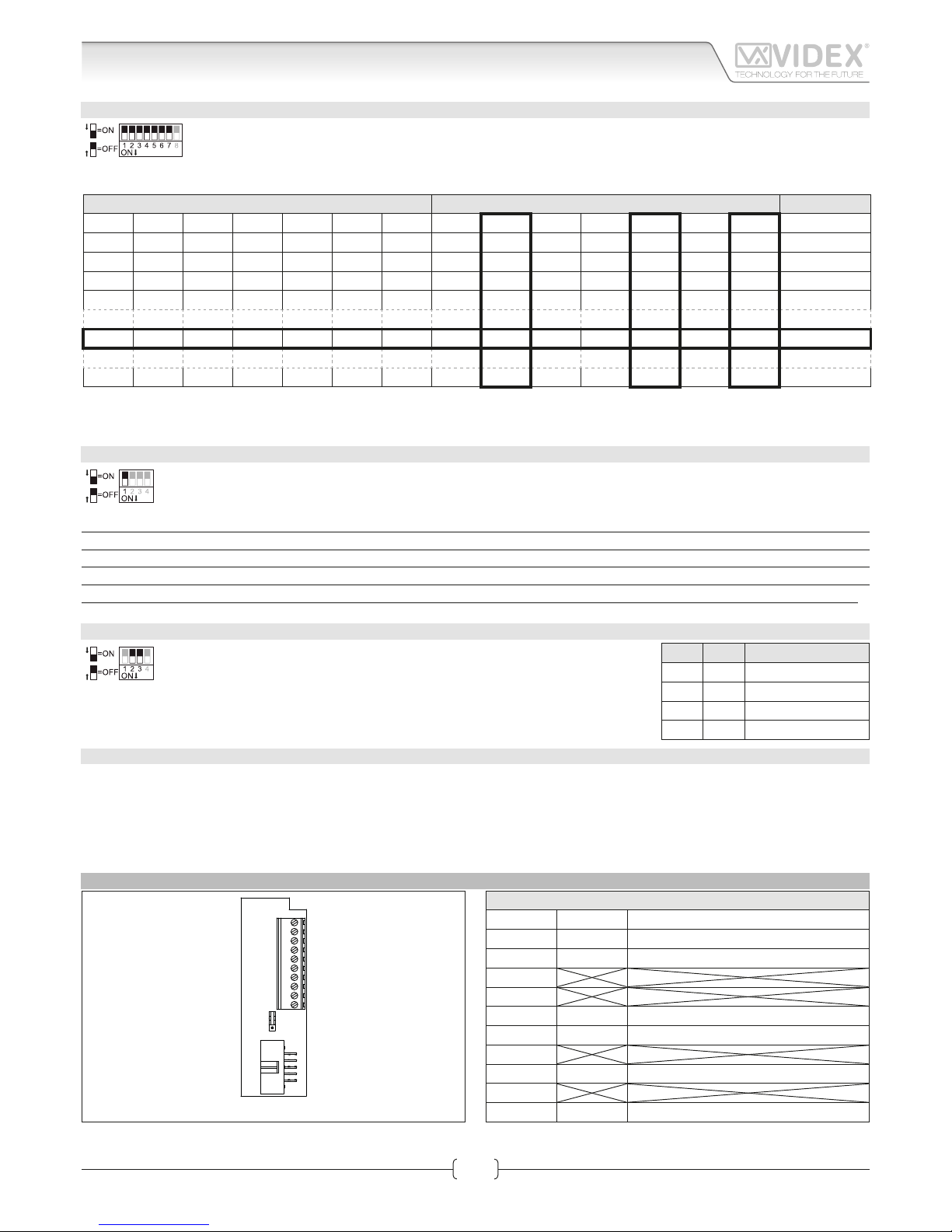
INTERCOM CONNECTION BOARD
A
B
JP1
1
2
3
4
5
6
7
8
9
10
Fig. 2
SIGNALS ON CONNECTION TERMINALS
Terminal Signal Description
1 GND Ground
2 LED Auxiliary LED +12Vdc input
3
4
5 LB Local bell active low input
6 AL Alarm input (not implemented yet)
7
8 BUS2 Bus input
9
10 BUS1 Bus input
2 3 EXTENSION NO.
OFF OFF 1 (default, master)
ON OFF 2 (slave)
OFF ON 3 (slave)
ON ON 4 (slave)
Page 4

66250800-EN - V2.0 - 08/04/15
4
5000 Series Eclipse Range
Art.5188 - Installation instructions
SPECIFICATION
Housing/Mounting: 5000 Series Intercoms / direct wall mount
Push buttons: Yes, 4
Programming: Yes, carried out by the dip-switches located on the rear of the videophone
Controls: Loudspeaker and call tone volume
Power Supply: Supplied by the BUS line
Power consumption: Stand-by: 0.7mA
Operating: 20mA
Working Temperature: -10 +50 °C
Art.5188 Hands free intercom
Page 5

66250800-EN - V2.0 - 08/04/15
5
5000 Series Eclipse Range
Art.5188 - Installation instructions
Art.5188 Hands free intercom
Page 6

66250800-EN - V2.0 - 08/04/15
6
5000 Series Eclipse Range
Art.5188 - Installation instructions
5000 Series Hands free intercom wall mounting instructions
A
B
Fig. 1
C
Fig. 2
135cm
Fig. 3
D
E
Fig. 4
A
B
Fig. 5
A
B
H
G
Fig. 6
1. As shown in Fig. 1, looking at the rear of the intercom, insert the tip of a at blade screwdriver into one of the two openings
(Fig. 1A) then slightly move the screwdriver in an upward direction to release the front from the back plate and opening the
intercom unit (Fig. 1B). Take care! The back plate of the intercom houses the pcb connection board which is normally connected
to the pcb in the front of the intercom by the ribbon cable, the ribbon cable should not be connected when rst opened.
2. Place the back plate of the intercom against the wall at approximately 135cm (Fig. 2) above nished oor level, then mark the
xing holes taking into account that the cable group A must feed into the opening B (Fig. 3).
3. As shown in Fig. 3, x the back plate of the intercom to the wall feeding the cable group A through opening B.
4. Using a at blade screwdriver connect the wires to the pcb connection board C as shown in Fig. 4, according to the installation
diagram provided.
5. Connect ribbon cable plug D from the front plate into plug E on the pcb connection board as shown in Fig. 5.
6. Close the intercom by hooking the front plate G to the back plate H as described below:
• Hook the top of the front plate
G
to the top of the back plate as shown by pointer A in Fig. 6.
• Move the lower side of the front plate G towards the back plate H and press until the unit locks into the back plate of the intercom.
To open the intercom once installed, rmly grasp the bottom sides of the front plate cover, pull forward in an upward direction to
separate the front cover from the back plate as in Fig. 6.
NB. Please take care when opening to avoid damage, remember that the ribbon cable connects the front plate to the back
plate connector pcb.
Page 7

66250800-EN - V2.0 - 08/04/15
7
5000 Series Eclipse Range
Art.5188 - Installation instructions
Note
Page 8

CUSTOMER SUPPORT
All Countries:
VIDEX ELECTRONICS S.P.A.
www.videx.it - technical@videx.it
Tel: +39 0734-631669
Fax: +39 0734-632475
UK Customers:
VIDEX SECURITY LTD
www.videx-security.com
Tech Line: 0191 224 3174
Fax: 0191 224 1559
The product is CE marked demonstrating its conformity and is for distribution within all member states of the EU with no restrictions. This product
follows the provisions of the European Directives 2004/108/ECC (EMC);
2006/95/ECC (LVD) and 93/68/ECC (CE marking).
Main UK oce:
VIDEX SECURITY LTD
1 Osprey Trinity Park
Trinity Way
LONDON E4 8TD
Phone: (+44) 0870 300 1240
Fax: (+44) 020 8523 5825
www.videx-security.com
marketing@videx-security.com
Northern UK oce:
VIDEX SECURITY LTD
Unit 4-7
Chillingham Industrial Estate
Chapman Street
NEWCASTLE UPON TYNE - NE6 2XX
Tech Line: (+44) 0191 224 3174
Phone: (+44) 0870 300 1240
Fax: (+44) 0191 224 1559
Greece oce:
VIDEX HELLAS Electronics
48 Filolaou Str.
11633 ATHENS
Phone: (+30) 210 7521028
(+30) 210 7521998
Fax: (+30) 210 7560712
www.videx.gr
videx@videx.gr
Danish oce:
VIDEX DANMARK
Hammershusgade 15
DK-2100 COPENHAGEN
Phone: (+45) 39 29 80 00
Fax: (+45) 39 27 77 75
www.videx.dk
videx@videx.dk
Benelux oce:
VIDEX BENELUX
E3 Iaan, 93
B-9800 DEINZE
Phone: (+32) 9 380 40 20
Fax: (+32) 9 380 40 25
www.videxbenelux.be
info@videxbenelux.be
VIDEX ELECTRONICS S.P.A.
Via del Lavoro, 1 - 63846 Monte Giberto (FM) Italy
Tel (+39) 0734 631669 - Fax (+39) 0734 632475
www.videx.it - info@videx.it
 Loading...