

Page 1
66250075-EN - V1.5 - 09/07/14
1
4000 Series
Art.4900 - 4900M - Installation instructions
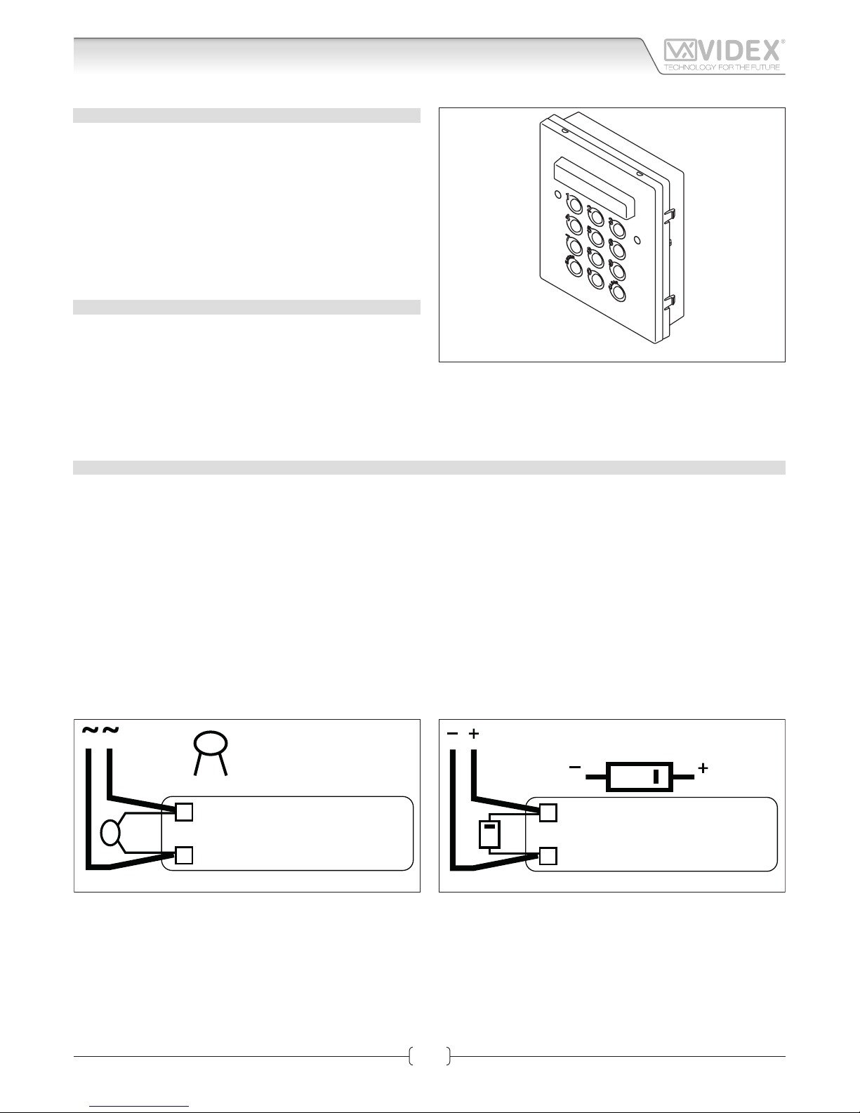
Art.4900 - 4900M Digital codelock module
CODELOCK UNIT MODULES ART.4900 4900M
This module has on the front a 12 stainless steel button keypad (keys from “0” to “9” plus “ENTER” and “CLEAR” keys), 2
LEDS for operation signalling, the keypad illumination LEDs and
a mirror stainless steel front plate (standard version). Codelock
unit module has 3 built-in relays that allow enabling up to 3 services (door-open, gate-open etc.) by typing the programmed
secret codes. Acoustic and visual (green and red front LEDs)
signals facilitate the use and the programming operations. This
module can be used individually or combined with other modules on an audio or video door entry system.
MAIN FEATURES
• 3 C, NC, NO relay outputs (24Vac/dc – 5A max);
• 100 Programmable secret codes (one for each relay);
• Each relay can be set to be activated for a specic time (01 to
99 seconds) or to work as latch;
• Two active low inputs to command directly the relay 1 and 2;
• Programming menu guarded by a 4-8 digit programmable secret code;
• Visual and Acoustic signal during operating and programming;
• Keypad illumination LEDs.
GENERAL DIRECTIONS FOR INSTALLATION
In order to achieve the best results from the schematics described it is necessary to install only original VIDEX equipment, strictly
keeping to the items indicated on each schematic and follow these General Directions for Installation:
• The system must be installed according to national rules in force, in any case the running of cables of any intercom unit must be
carried out separately from the mains;
• All multipair cables should be compliant to CW1308 specication (0.5mm twisted pair telephone cable).
• Cables for speech line and service should have a max resistance of 10 Ohm
• Lock release wires should be doubled up (Lock release wires and power supply wires should have a max resistance of 3 Ohm);
• The cable sizes above can be used for distances up to 50m. On distances above 50m the cable sizes should be increased to keep
the overall resistance of the cable below the RESISTANCES indicated above;
• Double check the connections before power up;
• Power up the system then check all functions.
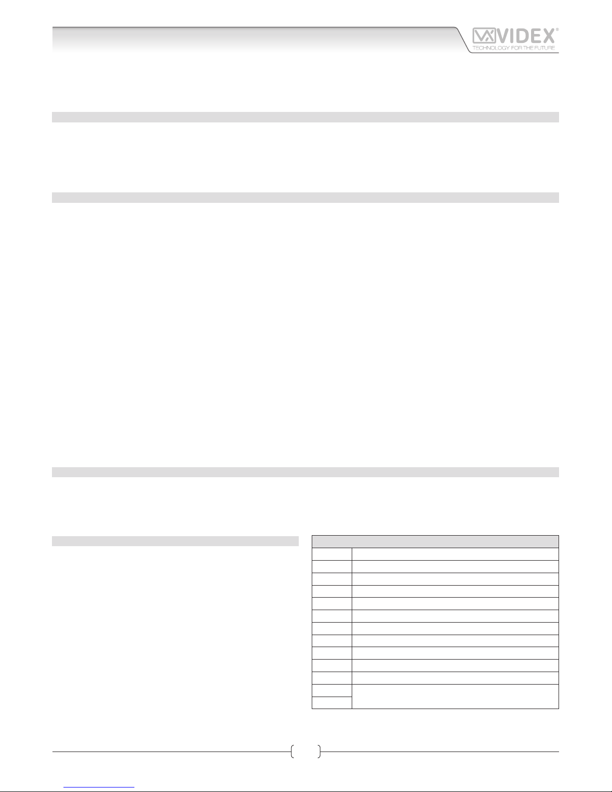
LOCK RELEASE BACK EMF PROTECTION
A varistor must be tted across the terminals on AC lock release
(Fig.1A)
and a diode must be tted across the terminals on a DC
lock release
(Fig.1B) to suppress back EMF voltages. Connect the components to the lock releases as shown in gures.
VARISTOR (MOV)
12V AC
LOCK RELEASE
Fig.1A
DIODE
1N4002
12V DC
LOCK RELEASE
Fig.1B
Fig. 1 - Art.4900 - 4900M
Page 2
66250075-EN - V1.5 - 09/07/14
2
4000 Series
Art.4900 - 4900M - Installation instructions
BUZZER BACK EMF
When using intercoms with buzzer call (Art.924/926, SMART1/2, 3101/2, 3001/2 and 3021/2) add one 0,1uF capacitor between
terminals 6 and 3.
BUILTIN RELAYS BACK EMF PROTECTION ART.4900M
The Art.4900M includes selectable back EMF protection on the relays. The jumpers marked MOV (One jumper for each relay) are
used to select the protection type. When using a fail secure lock with connections C & NO the jumper should be in the NO position.
When using a fail open lock with connections C & NC the jumper should be in the NC position and when using the codelock to
trigger a gate controller or another third party controller the jumper should be removed completely (This disables the protection
on the relay).
PROGRAMMING SEE ALSO THE RELEVANT FLOW CHART
• Enter the “MASTER CODE”: rst time type 8 times “1” (11111111 factory preset) and press “ENTER” (The red LED will illuminate);
• Conrm “MASTER CODE” (typing again the same) or type the new one (4 to 8 digits) then press “ENTER” (Melody). Pressing twice
the “ENTER” button without changing the “MASTER CODE”, will exit from the programming;
• Enter the “USER NUMBER” (2 digits from 00 to 99) then press “ENTER” (Melody);
• Now you can do two dierent operations:
1. If you press “CLEAR” the code relevant to the “USER NUMBER” entered is deleted and the system go back to “USER NUMBER”
entering (melody);
2. Enter the “USER CODE” (4 to 8 digits) then press “ENTER” (Melody). The user code must be prexed with 1 digit that specify
the relay to operate: 0 relay 1 and 2, 1 relay 1, 2 relay 2 and 3 relay 3. I.E. the code 148325 would operate the relay 1 only.
• The system go back to “USER NUMBER” entering. Continue as above to delete or enter other codes or press twice “ENTER” to
jump to next programming step (Melody);
• Enter the “RELAY 1” operation time (2 digits 01 to 99 I.E. 05=5 seconds, 00= remain open time) or leave the existing time then
press “ENTER” (Melody);
• Enter the “RELAY 2” operation time (2 digits 01 to 99 I.E. 05=5 seconds, 00= remain open time) or leave the existing time then
press “ENTER” (Melody);
• Enter the “RELAY 3” operation time (2 digits 01 to 99 I.E. 05=5 seconds, 00= remain open time) or leave the existing time then
press “ENTER” (Melody);
• The system is ready to use (the red LED will be o).
PROGRAMMING NOTES
• After the conrmation of an entered data by pressing the “ENTER” button, by pressing twice the same button you can exit from
the programming.
RETURN SYSTEM TO PRESET MASTER FACTORY CODE
• Turn o power to code lock;
• Keep “ENTER” button pressed while turning back on the power;
• Release “ENTER” button;
• The master code is now set at “11111111” (eight times one).
OPERATION
• Type in the programmed code and press “ENTER”;
• If the code is right, the green LED will illuminate and the relay will operate for the programmed time;
• If a wrong code is “ENTER”ed, a continuous melody will
sound for 4 or more seconds, according to the number of
mistakes;
• To switch o any relay while operating, type in the relevant
code then press the “CLEAR” button.
OPERATION NOTES
• To operate relays together, set the same code for each relay;
• If a wrong code is entered, the system will lock out for 5 seconds which will increase each time a wrong code is entered.
The system will operate only when the correct code is entered.
TERMINALS:
SW2 Relay 2 command signal (active low)
SW1 Relay 1 command signal (active low)
NC3 Relay 3 normally closed contact
NO3 Relay 3 normally open contact
C3 Relay 3 common contact
NC2 Relay 2 normally closed contact
NO2 Relay 2 normally open contact
C2 Relay 2 common contact
NC1 Relay 1 normally closed contact
NO1 Relay 1 normally open contact
C1 Relay 1 common contact
12/24Vac/dc power input
+
Art.4900 - 4900M Digital codelock module
Page 3
66250075-EN - V1.5 - 09/07/14
3
4000 Series
Art.4900 - 4900M - Installation instructions
TECHNICAL SPECIFICATION
Power Supply: 12/24 Vac/dc
Power Consumption: – 2A 30mA max
Working Temperature: -10 +50° C
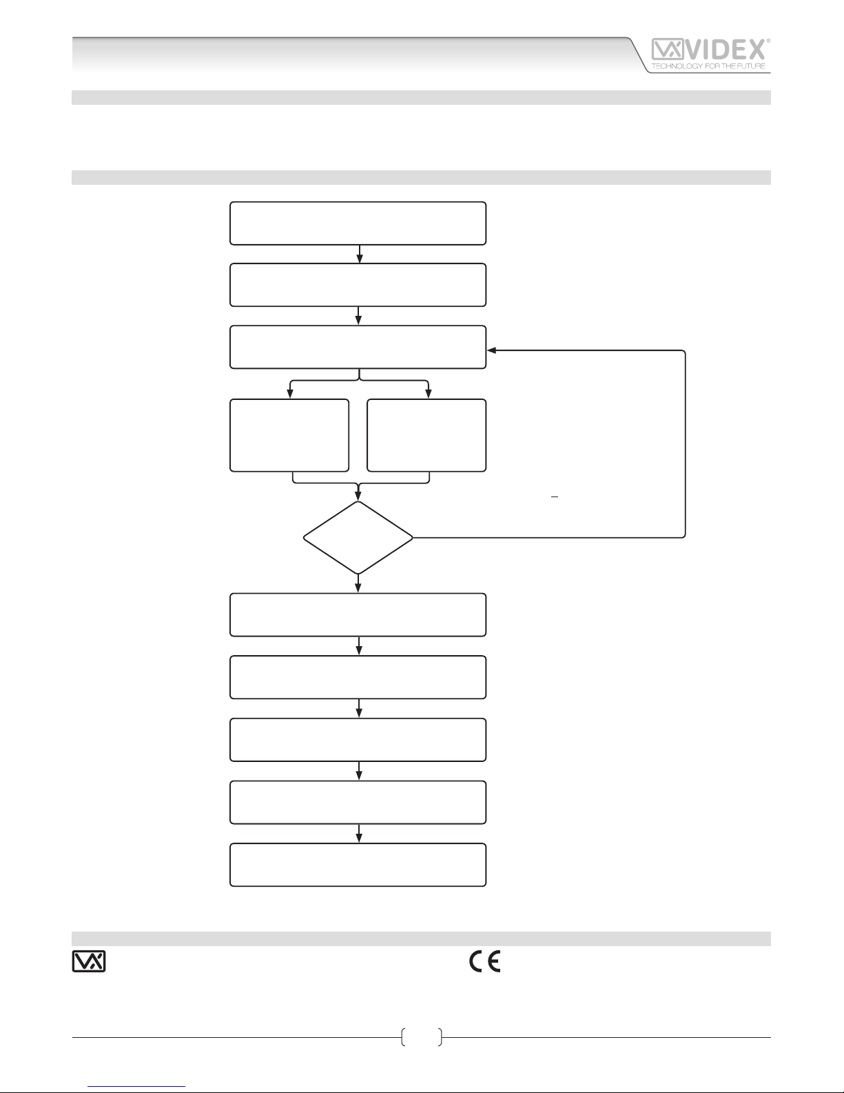
PROGRAMMING FLOWCHART
ENTER “MASTER CODE“
AND PRESS “ENTER“
CONFIRM OR CHANGE “MASTER CODE“
AND PRESS “ENTER“
ENTER “USER NUMBER“
AND PRESS “ENTER“
PRESS “ENTER“ TWICE
ENTER “RELAY 1 TIME”
AND PRESS “ENTER“
ENTER “RELAY 2 TIME”
AND PRESS “ENTER“
ENTER “RELAY 3 TIME”
AND PRESS “ENTER“
SYSTEM READY TO USE
PRESS “CLEAR” TO
DELETE THE USER
RELEVANT CODE
AND PRESS “ENTER“
ENTER
“USER CODE“
AND PRESS
“ENTER“
OTHER
CODES?
First time 8 times 1 "11111111"
factory preset
Type again eight times “1”
or the new code 4 to 8 digits
2 digits (from 00 to 99)
2 digits (01 - 99)
I.E. 05 = 5 seconds
00 = remain open time
2 digits (01 - 99)
I.E. 05 = 5 seconds
00 = remain open time
2 digits (01 - 99)
I.E. 05 = 5 seconds
00 = remain open time
Red LED will be ON
Red LED will be OFF
Melody
Melody
Melody
Melody
Melody
Melody
Melody
IMPORTANT:
4 to 8 digits. Code must be prexed with relay number.
0 = relay 1 and 2;
1 = relay 1;
2 = relay 2;
3 = relay 3.
I.E. code 148325 would operate
Relay 1 only.
NO
YES
Art.4900 - 4900M Digital codelock module
COSTUMER SUPPORT
All Countries:
VIDEX ELECTRONICS S.P.A.
www.videx.it - technical@videx.it
Tel: +39 0734-631669
Fax: +39 0734-632475
UK Customers:
VIDEX SECURITY LTD
www.videx-security.com
Tech Line: 0191 224 3174
Fax: 0191 224 1559
The product is CE marked demonstrating its conformity and is for distribution within all member states of the EU with no restrictions. This product
follows the provisions of the European Directives 2004/108/ECC (EMC);
2006/95/ECC (LVD) and 93/68/ECC (CE marking).
Main UK offi ce:
VIDEX SECURITY LTD
1 Osprey Trinity Park
Trinity Way
LONDON E4 8TD
Phone: (+44) 0870 300 1240
Fax: (+44) 020 8523 5825
www.videx-security.com
marketing@videx-security.com
Northern UK offi ce:
VIDEX SECURITY LTD
Unit 4-7
Chillingham Industrial Estate
Chapman Street
NEWCASTLE UPON TYNE - NE6 2XX
Tech Line: (+44) 0191 224 3174
Phone: (+44) 0870 300 1240
Fax: (+44) 0191 224 1559
Greece offi ce:
VIDEX HELLAS Electronics
48 Filolaou Str.
11633 ATHENS
Phone: (+30) 210 7521028
(+30) 210 7521998
Fax: (+30) 210 7560712
www.videx.gr
videx@videx.gr
Danish offi ce:
VIDEX DANMARK
Hammershusgade 15
DK-2100 COPENHAGEN
Phone: (+45) 39 29 80 00
Fax: (+45) 39 27 77 75
www.videx.dk
videx@videx.dk
Benelux offi ce:
VIDEX BENELUX
E3 Iaan, 93
B-9800 DEINZE
Phone: (+32) 9 380 40 20
Fax: (+32) 9 380 40 25
www.videxbenelux.be
info@videxbenelux.be
VIDEX ELECTRONICS S.P.A.
Via del Lavoro, 1 - 63846 Monte Giberto (FM) Italy
Tel (+39) 0734 631669 - Fax (+39) 0734 632475
www.videx.it - info@videx.it
Page 4

66250075-EN - V1.5 - 09/07/14
4
4000 Series
Art.4900 - 4900M - Installation instructions
DATA LIST CODE STORED INTO MEMORY
Art.4900 - 4900M Digital codelock module
Page 5

66250075-EN - V1.5 - 09/07/14
5
4000 Series
Art.4900 - 4900M - Installation instructions
Art.4900 - 4900M Digital codelock module
Page 6

66250075-EN - V1.5 - 09/07/14
6
4000 Series
Art.4900 - 4900M - Installation instructions
Art.4900 - 4900M Digital codelock module
Page 7

66250075-EN - V1.5 - 09/07/14
7
4000 Series
Art.4900 - 4900M - Installation instructions
Art.4900 - 4900M Digital codelock module
Page 8

66250075-EN - V1.5 - 09/07/14
8
4000 Series
Art.4900 - 4900M - Installation instructions
Art.4900 - 4900M Digital codelock module
 Loading...