

Page 1
4000 Series
ENG
Art.4871 - 4872 - 4873
Rainshields for 4000 Series ush mounting boxes Art.4851, 4852 and 4853
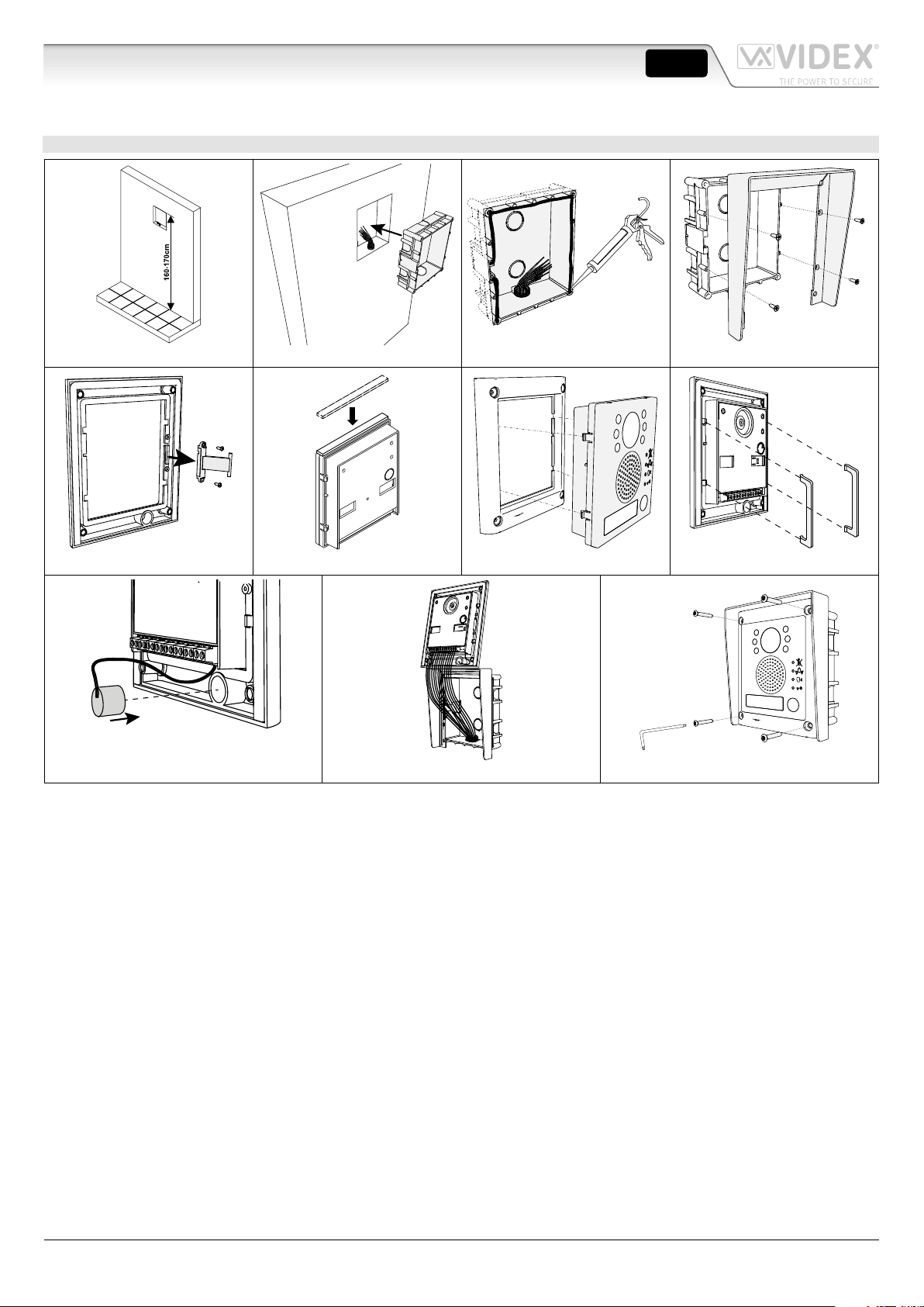
EXAMPLE OF ART.4871 INSTALLATION
Fig. 1 Fig. 2 Fig. 3 Fig. 4
Fig. 5 Fig. 6 Fig. 7 Fig. 8
Fig. 9 Fig. 10 Fig. 11
1. Prepare the ush-mounting of the box in the wall 160-170 cm between the height of the box and the ground, as well as the
cable routing. (Fig. 1)
2. Cut out a hole in the ush-mounted box for the cables to pass through. Seal the ush-mounted box in the wall. (Fig. 2)
3. Make a silicone seal on the top front part of the ush-mounted box and on the sides. (Fig. 3)
4. Attach the shield to the ush-mounted box using the four screws provided. (Fig. 4)
5. Remove the hinge from the frame. (Fig. 5)
6. Place the self-adhesive silicone band on the top part of the door station module. (Fig. 6)
7. Clip the door station module onto its frame. (Fig. 7)
8. Clip the two locking plates into place on the rear of the door station module. (Fig. 8)
9. Install the microphone in position at the bottom of the frame. (Fig. 9)
10. Position the frame and door station in such a manner as to cable it and access the settings: see the door station installation guide.
Note: Protect the front face of the door station to prevent accidental scratches.
11. After testing the installation to check it works correctly, close the frame gently while making sure not to trap microphone wires.
Tighten the four tamperpro of Torx screws with the key provided. (Fig. 11)
(Fig. 10)
4000 Series rainshields - Mounting instructions
66800017-EN - V1.0 - 31/01/17
Page 2
4000 Series
CUSTOMER SUPPORTMANUFACTURER
VIDEX ELECTRONICS S.P.A.
Via del Lavoro, 1 - 63846 Monte Giberto (FM) Italy
Tel (+39) 0734 631669 - Fax (+39) 0734 632475
www.videx.it - info@videx.it
The product is CE marked demonstrating its conformity and is for distribution
ENG
Art.4891 - 4892 - 4893
Rainshields for 4000 Series surface mounting boxes Art.4881, 4882 and 4883
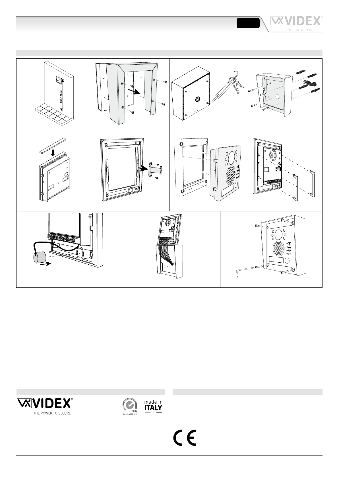
EXAMPLE OF ART.4891 INSTALLATION
Fig. 1 Fig. 2 Fig. 3 Fig. 4
Fig. 5 Fig. 6 Fig. 7 Fig. 8
Fig. 9 Fig. 10 Fig. 11
1. Prepare the mounting of the box on the wall 160-170 cm between the height ofthe box and the ground, where the cables are
to be routed. (Fig. 1)
2. Attach the shield to the base of the surface-mounted box using the four screws provided. (Fig. 2)
3. Make a silicone seal on the top rear part of the surface-mounted box, on the sides and around the cutout for the cable routing. (Fig. 3)
4. Attach the surface-mounted box using the screws and suitable plugs, without forgetting to route the cables. (Fig. 4)
5. Place the self-adhesive silicone band on the top part of the door station module. (Fig. 5)
6. Remove the hinge from the frame. (Fig. 6)
7. Clip the door station module onto its frame. (Fig. 7)
8. Clip the two locking plates into place on the rear of the door station module. (Fig. 8)
9. Install the microphone in position at the bottom of the frame. (Fig. 9)
10. Position the frame and door station in such a manner as to cable it and access the settings: see the door station installation guide.
Note: Protect the front face of the door station to prevent accidental scratches.
11. After testing the installation to check it works correctly, close the frame gently while making sure not to trap microphone wires.
Tighten the four tamper-proof Torx screws with the key provided. (Fig. 11)
(Fig. 10)
4000 Series rainshields - Mounting instructions
All Countries:
VIDEX ELECTRONICS S.P.A.
www.videx.it - technical@videx.it
Tel: +39 0734-631669
Fax: +39 0734-632475
within all member states of the EU with no restrictions. This product follows
the provisions of the European Directives 2014/30/EU (EMC); 2014/35/EU
(LVD); 2011/65/EU (RoHS): CE marking 93/68/EEC.
UK Customers:
VIDEX SECURITY LTD
www.videx-security.com
Tech Line: 0191 224 3174
Fax: 0191 224 1559
66800017-EN - V1.0 - 31/01/17
 Loading...