

Page 1
Rev.1.4 19/09/2012 PrtCode:66250240.doc
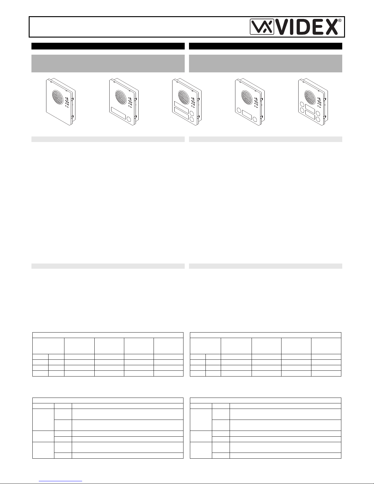
Art.4838
Speaker Unit
Portiere Elettrico
INSTALLATION INSTRUCTION
ISTRUZIONI D’INSTALLAZIONE
4838 SERIES - FOR AUDIO DOOR ENTRY SYSTEMS “4+1”,
“5+1” WITH PRIVACY OF SPEECH, INTERCOMMUNICATING
AND VIDEO
SERIE 4838 - PER SISTEMI CITOFONICI “4+1”, “5+1” CON
SEGRETO DI CONVERSAZIONE, INTERCOMUNICANTI E
VIDEO
Art.4838-0
Art.4838-1
Art.4838-2
Art.4838-1D
Art.4838-2D
ART.4838-0, -1, -2, -1D, 2D
4838 series speaker units are intelligent devices with a built-in
microprocessor to control the operations. This speaker unit offers easy of
installation (on audio door entry systems with multiple entrances there are
no audio entrance Art.502N switchers required) and assists the user by
providing a number of visual and acoustic signals during normal system
operation (call, conversation etc).
The speaker unit circuitry includes:
a. The microprocessor;
b. The transmitting amplifier with condenser microphone and volume
control;
c. The receiving amplifier and volume control;
d. 2 LEDs to illuminate the name plate (except the 4838-0 model).
e. 4 LEDs for operation visual signalling;;
f. The lock release relay to enable the electric lock;
g. The modulated tone generator;
h. Two programming DIP-SWITCHES one 3 way and one 8 way.
This speaker unit together with a camera module Art.4830, can be used
on video door entry systems. On systems with two or more entrances,
there is no video entrance exchangers Art.892 required. Standard
Art.506N relays can be used instead.
SPEAKER UNIT PROGRAMMING
Two dip switch sets are accessible from the back of the module allowing
the setup of the following parameters:
DIP-SWITCH 1 (8 way)
− The call tone, choose between 4 different tones (switches 1,2);
− The number of rings (switches 3,4 – only for “5+1” systems));
− The conversation time duration (switches 5, 6);
− The door opening time duration (switches 7,8);
DIP-SWITCH 2 (3 way)
− The reassurance tone enabling/disabling (switch 1);
− The system type (“4+1” or “5+1” with privacy of speech).
ART.4838-0, -1, -2, -1D, -2D
I portieri della serie 4838 sono di tipo intelligente ed incorporano un
microprocessore per la gestione di tutte le funzioni. Oltre a consentire una
facile installazione (nei sistemi citofonici multi-ingresso non richiedono lo
scambiatore d’ingressi Art.502N), questi portieri agevolano gli utenti del
sistema fornendo segnalazioni acustiche e visive in merito al
funzionamento dell’impianto (chiamata, conversazione ecc.).
L’elettronica del portiere elettrico comprende:
a. Il microprocessore
b. L’amplificatore di trasmissione con microfono a condensatore e
regolazione del volume;
c. L’amplificatore di ricezione con altoparlante da 0,5W e regolazione del
volume;
d. 2 LED d’illuminazione cartellini (escluso 4838-0);
e. 4 LED per le indicazioni visive in merito al funzionamento dell’impianto;
f. Il relè d’asservimento per l’attivazione della serratura elettrica;
g. Il circuito di generazione della nota elettronica;
h. 2 DIP-SWITCH di programmazione a 3 e ad 8 vie.
Questo portiere, in abbinamento al modulo telecamera Art.4830, può
essere impiegato anche in sistemi videocitofonici: in tal caso, nei sistemi a
più ingressi, consente di sostituire gli scambiatori d’ingressi video Art.892
con dei semplici relé Art.506N.
PROGRAMMAZIONE PORTIERE ELETTRICO
La configurazione dei due DIP-SWITCH accessibili dal retro del modulo
permette di impostare i seguenti parametri:
DIP-SWITCH 1 (8 vie)
− Il tono di chiamata selezionabile tra 4 differenti (switch 1,2);
− Il numero di squilli (switch 3,4 – solo per sistemi “5+1”);
− La durata del “tempo di conversazione” (switch 5,6);
− La durata del “tempo d’apertura porta” (switch 7,8);
DIP-SWITCH 2 (3 vie)
− L’abilitazione/disabilitazione del tono di conferma chiamata (switch 1);
− Il tipo di sistema (“4+1” o “5+1” con segreto di conversazione).
8 WAY DIP-SWITCH (DIP-SWITCH 1)
SWITCHES/
STATUS
CALL
MELODY
1,2
RINGS
NUMBER
3,4
CONVER.
TIME
5,6
DOOR OP.
TIME
7,8
OFF OFF
MELODY 1 2 30s 1s
ON OFF
MELODY 2 4 60s 4s
OFF ON
MELODY 3 6 90s 8s
ON ON
MELODY 4 8 120s 16s
To set the number of rings is useful only on “5+1” systems: when the
speaker unit is set to work with “4+1” systems, the intercom/videophone
called will ring (2 seconds max) each time the call button is pressed.
3 WAY DIP-SWITCH (DIP-SWITCH 2)
Switch Status Function
1
OFF
Reassurance tone disabled
ON
Reassurance tone enabled ( a tone confirms that
the call is made)
2
OFF
“4+1” system
ON
“5+1” system (with privacy of speech)
3
ON
Automatic recall when the handset is picked up
(only “4+1)”
OFF
Normal operation.
DIP-SWITCH a 8 vie (DIP-SWITCH 1)
SWITCH /
STATO
TONO
CHIAMATA
1,2
NUMERO
SQUILLI
3,4
TEMPO
CONV.
5,6
TEMPO
AP.PORTA
7,8
OFF OFF TONO 1 2 30s 1s
ON OFF TONO 2 4 60s 4s
OFF ON TONO 3 6 90s 8s
ON ON TONO 4 8 120s 16s
L’impostazione del numero di squilli è valida solo per il sistema “5+1”:
quando il portiere è impostato per sistemi “4+1”, il citofono/videocitofono
suona per un massimo di 2 secondi ogni volta che il pulsante di chiamata
viene premuto.
DIP-SWITCH a 3 vie (DIP-SWITCH 2)
Switch Stato Funzione
1
OFF
Tono di conferma chiamata disabilitato
ON
Tono di conferma chiamata abilitato (un tono
segnala che la chiamata è in corso)
2
OFF Sistema “4+1”
ON Sistema “5+1” (con segreto di conversazione)
3
ON
Accensione automatica impianto sollevando la
cornetta (solo sistema “4+1”)
OFF Funzionamento normale.
Page 2
Rev.1.4 19/09/2012 PrtCode:66250240.doc
FRONT LEDS – SIGNALLING DESCRIPTION
Sign Description
When illuminated, indicates that it is not possible to make a
call because a call or a conversation is in progress (from
the outdoor station from which you are calling or from
another outdoor station on systems with multiple
entrances). The LED will be off when the system is in
stand-by
If illuminated, indicates that the call from the outdoor station
is in progress. The LED will switch OFF when the call is
answered or after the programmed number of rings.
If illuminated, indicates that it is possible to speak because
the call has been answered. The LED will switch OFF at the
end of a conversation (or at the end of the conversation
time).
If illuminated, indicates that the door lock has been
operated. It will switch OFF at the end of the programmed
“door opening” time.
TERMINALS:
1
Speech in (toward the speaker)
2
Speech out (from the microphone)
+12
+12Vdc power input
GND
Ground
5
Door Open command (input active low))
PTE
Local Door open command (input active low))
C
Relay - common contact
NC
Relay - normally closed contact
NO
Relay - normally open contact
BSY
Busy signal (input/output active low)
SL
Video power supply and/or exchanger enabling signal (output
active low)
F1
Camera enabling signal (output active low)
LB
Local bell electronic call tone (output square wave 12Vpp)
T
Main call tone (output square wave 12Vpp)
CB
Enabling signal for intercoms with privacy of speech (for “5+1”
systems.
COM
Push button common
P1 Output call button 1 (available on all versions except -0)
P2 Output call button 2 (available only on -2 and -2D versions)
P3 Output call button 3 (available only on -1D and -2D versions)
P4 Output call button 4 (available only on -2D version)
LED FRONTALI – DESCRIZIONE INDICAZIONI
Simbolo Descrizione
Se acceso, indica che non è possibile chiamare a causa di
una chiamata o conversazione in corso, dal posto esterno
in uso o da un altro posto esterno in caso di sistemi a più
ingressi. Il LED si spegne con l’impianto a riposo (nessuna
conversazione o chiamata in corso).
Se acceso, indica che è in corso la chiamata dal posto
esterno che si sta utilizzando. Il LED si spegne alla
risposta dell’utente chiamato o al raggiungimento del
numero di squilli programmati.
Se acceso, indica che l’utente chiamato ha risposto e la
conversazione può avere inizio. Il LED si spegne al termine
della conversazione (l’utente chiamato riaggancia la
cornetta) o allo scadere del “tempo di conversazione”
programmato.
Se acceso, indica che l’utente chiamato ha aperto la porta.
Il LED resta acceso per tutto il “tempo d’apertura porta”
programmato.
MORSETTIERA:
1 Audio in (verso lo speaker del portiere)
2 Audio out (dal microfono del portiere)
+12 Ingresso d’alimentazione +12Vdc
GND Massa
5 Comando “apri-porta” (input attivo basso)
PTE Comando “apri-porta” locale (input attivo basso)
C Relé - contatto comune
NC Relé - contato normalmente chiuso
NO Relé - contatto normalmente aperto
BSY Segnale d’occupato (input/output attivo basso)
SL
Segnale d’abilitazione alimentatore video e/o scambiatore
(output attivo basso)
F1 Abilitazione telecamera (output attivo basso)
LB
Nota elettronica per campanello di piano (output onda quadra
12Vpp)
T Nota elettronica di chiamata (output onda quadra 12Vpp)
CB
Segnale d’abilitazione citofoni con segreto di conversazione
(sistemi “5+1” output 12Vdc)
COM Comune pulsanti
P1 Uscita pulsante 1 (disponibile in tutte le versioni eccetto -0)
P2 Uscita pulsante 2 (disponibile solo nelle versioni -2 e -2D)
P3 Uscita pulsante 3 (disponibile solo nelle versioni -1D e -2D)
P4 Uscita pulsante 4 (disponibile solo nella versione -2D)
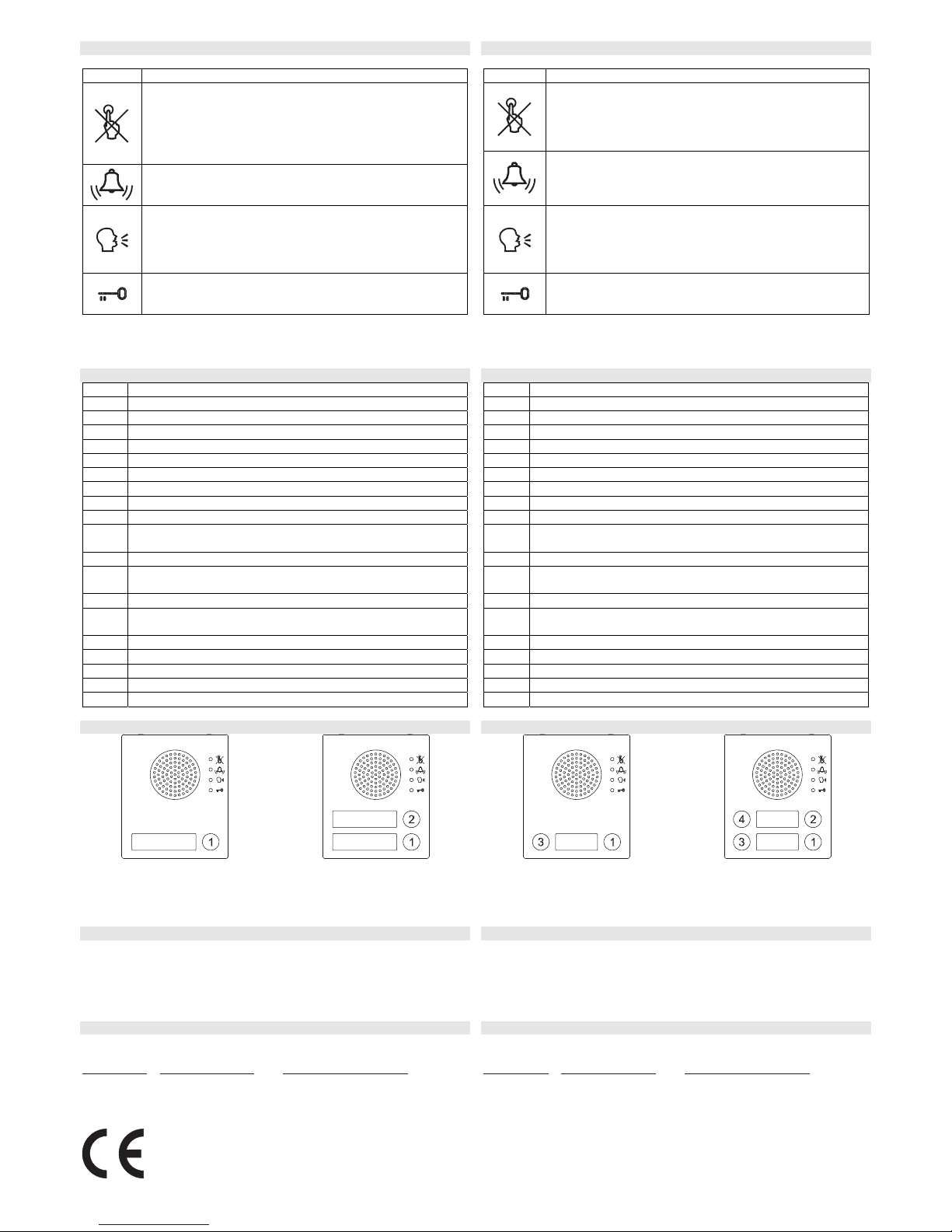
BUTTON LAYOUT ORDINE PULSANTI
Art.4838-1 Art.4838-2 Art.4838-1D Art.4838-2D
TECHNICAL SPECIFICATION
Power Supply: 12Vdc
Power Consumption: Approx. 25mA - stand-by
Approx. 150mA - during a call
Approx. 70mA - during a conversation
Working Temperature: -10 +50 C
SPECIFICHE TECNICHE
Tensione d’alimentazione: 12Vdc
Assorbimento: circa 70mA in stand-by
circa 200mA durante la chiamata
circa 100mA durante la conversazione
Temperatura di lavoro: -10 +50 C
CUSTOMER SUPPORT INFORMATION INFORMAZIONI ASSISTENZA CLIENTI
All Countries Customers UK Customers Clienti di tutti i Paesi Clienti UK
VIDEX Electronics S.p.A.
www.videx.it – technical@videx.it
Tel.+39 0734 631669
Fax +39 0734 632475
VIDEX Security LTD
www.videx-security.com
Tech Line 0191 224 3174
Fax 0191 224 1559
VIDEX Electronics S.p.A.
www.videx.it – technical@videx.it
Tel.+39 0734 631669
Fax +39 0734 632475
VIDEX Security LTD
www.videx-security.com
Tech Line 0191 224 3174
Fax 0191 224 1559
The product is CE marked demonstrating its conformity and is for distribution within all
member states of the EU with no restrictions.
This product follows the provisions of the European Directives
89/336/EEC & 92/31/EEC (EMC),
73/23/EEC (LVD) and 93/68/EEC (CE marking).
Il prodotto è marchiato CE a dimostrazione della sua conformità e può essere distribuito
liberamente all’interno dei paesi membri dell’unione e uropea EU.
Questo prodotto è conforme alle direttive Europee
89/336/EEC & 92/31/EEC (EMC),
73/23/EEC (LVD) e 93/68/EEC (Marcatura CE).
Page 3

Rev.1.4 19/09/2012 PrtCode:66250240.doc
Page 4

Rev.1.4 19/09/2012 PrtCode:66250240.doc
 Loading...