

Page 1
66251360-EN - V2.0 - 14/10/15
1
4000 Series
Art.4303N - Installation instructions
Art.4303N Speaker unit module with built-in functional to digital interface
White
Red
Blue
D
A
B
C
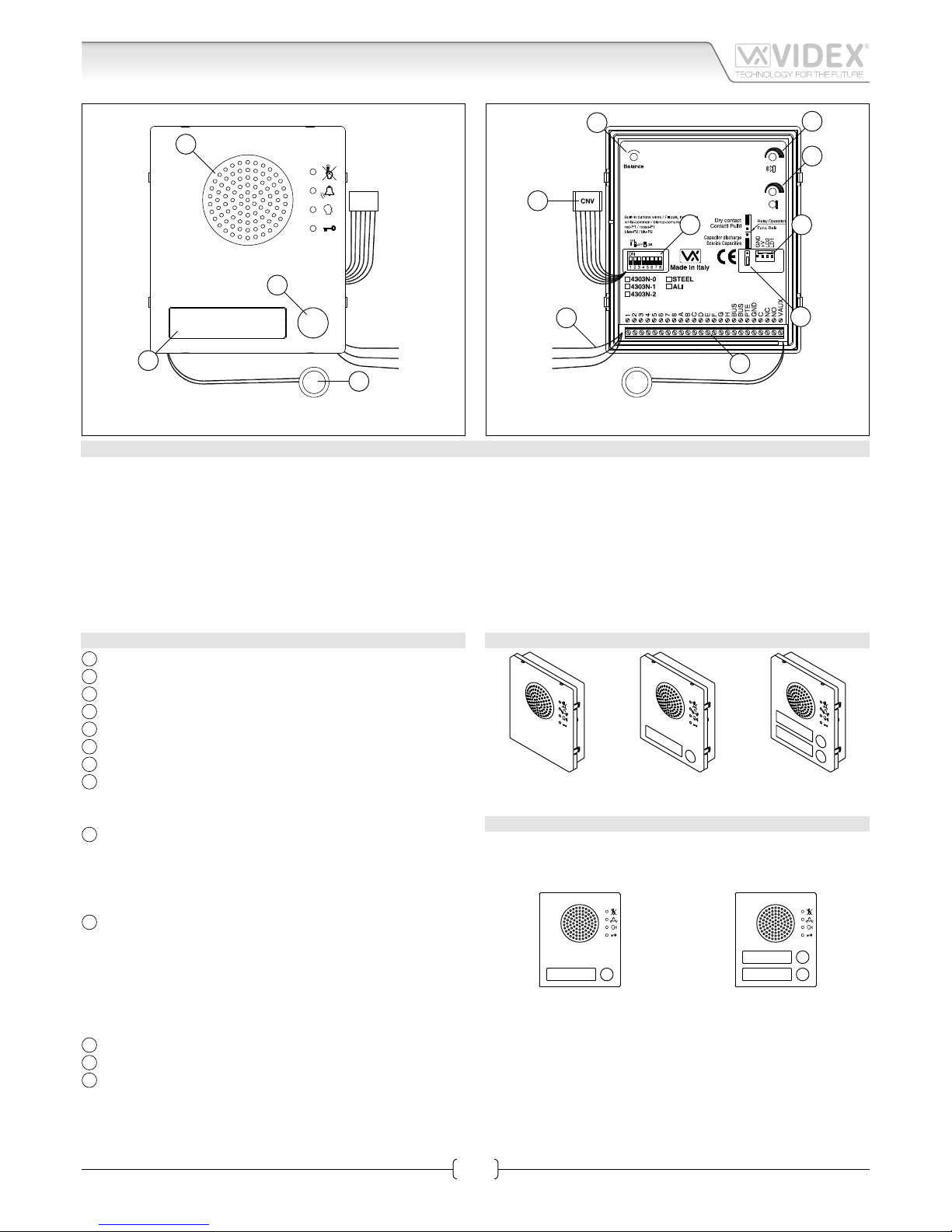
Fig. 1
White
Red
Blue
L
M
J I
K
G
H
F
E
Fig. 2
DESCRIPTION
Functional speaker module for up to 64 traditional call buttons. The unit circuitry incorporates :
• The transmitting amplier with condenser microphone and volume control;
• The receiving amplier with volume control;
• The audio balance circuit with the “BALANCE” control;
• The enslavement relay to enable the electric lock (3 contacts: common, normally open and normally closed). It can also operate
as capacitor discharge to power directly the electric lock;
• The call buttons from 0 to a maximum of 2 depending on the module version;
• The illumination LEDs for the card name holder.
The module is available in 3 versions according to the number of built-in push buttons.
MODULE DETALIS:
A
Loudspeaker;
B
Call push button (0 up to 2 according to the model);
C
Card name holder;
D
Microphone;
E
Balance control;
F
Loudspeaker volume Control;
G
Microphone volume control;
H
Door relay operating mode jumper:
• Lower position for capacitor discharge;
• Upper position for dry contacts;
I
Connector to supply button expansion modules:
• 3 modules can be connected between LD1 and GND;
• 3 modules can be connected between LD2 and GND;
• +V is 30V output with no current regulation to supply 3
button expansion modules connected in series;
J
Dip-switch to carry out the following programming:
• Door station ID (switches 1 to 3);
• Door opening time (switch 4);
• Conversation time (switch 5);
• Oset (switch 6);
• Camera selection order (switch 7);
• Art.2306 block mode (switch 8);
K
System connection terminals;
L
CNV connector to link to Art.4330N camera module;
M
Wires to congure built-in buttons:
• White = Common;
• Red = P1;
• Blue = P2
AVAILABLE MODULE VERSIONS
Art.4303N-0 Art.4303N-1 Art.4303N-2
BUTTONS LAYOUT
As factory preset, built-in buttons are congured to call address
1 or 1 & 2 but the setup may be changed by altering the position
of the 3 wires shown in Fig. 2 with reference “M”.
1
Art.4303N-1
1
2
Art.4303N-2
Page 2
66251360-EN - V2.0 - 14/10/15
2
4000 Series
Art.4303N - Installation instructions
Art.4303N Speaker unit module with built-in functional to digital interface
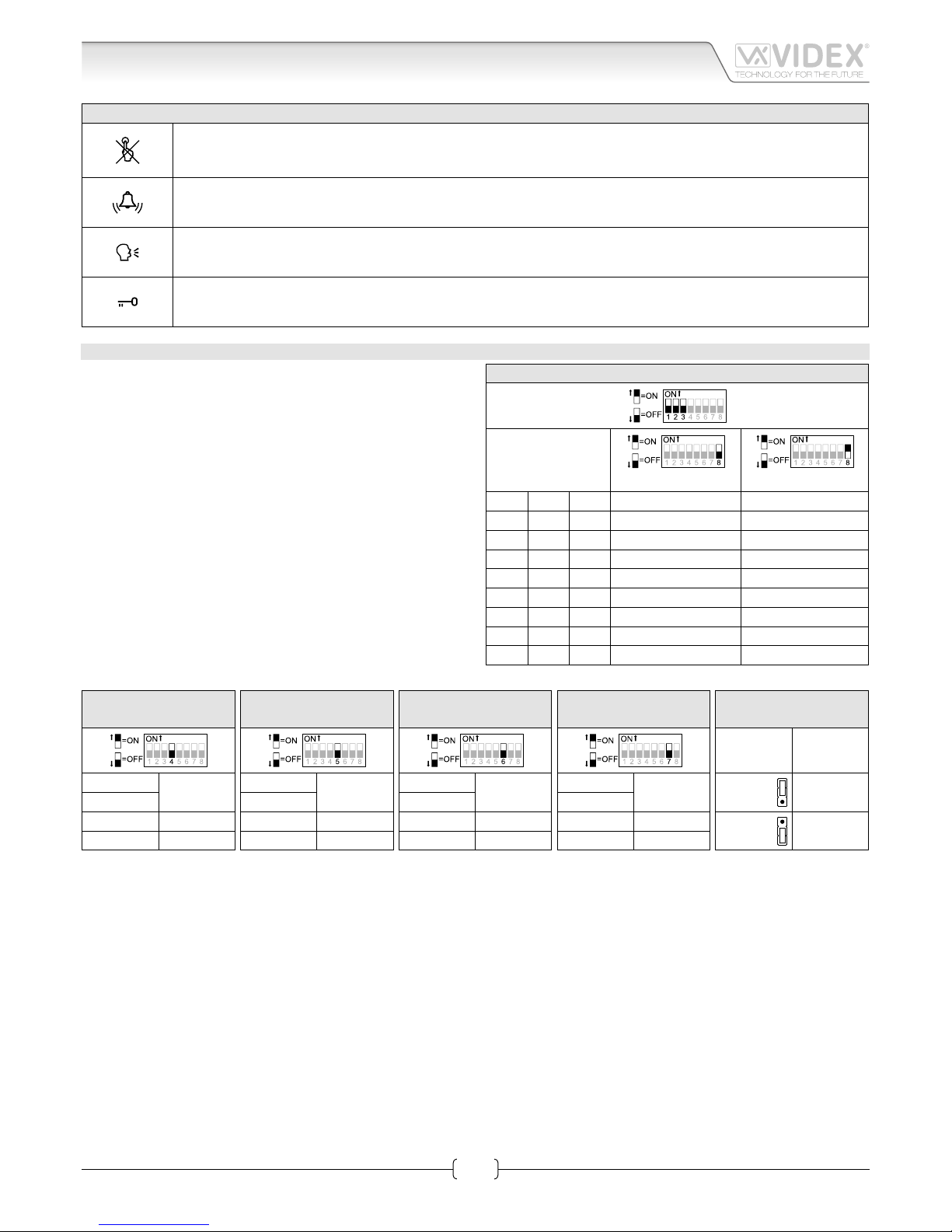
FRONT LEDS SIGNALLING DESCRIPTION
When illuminated, indicates that it is not possible to make a call because a call or a conversation is in progress (from
the outdoor station from which you are calling or from another outdoor station on systems with multiple entrances). The LED will be o when the system is in stand-by
If illuminated, indicates that the call from the outdoor station is in progress. The LED will switch OFF when the call
is answered or after the programmed number of rings.
If illuminated, indicates that it is possible to speak because the call has been answered. The LED will switch OFF at
the end of a conversation (or at the end of the conversation time).
If illuminated, indicates that the door lock has been released. It will switch OFF at the end of the programmed “door
opening” time.
PROGRAMMING
The programming consists of the following settings:
• Unit ID (1..8);
• Door Opening Time (2 or 6 seconds);
• Conversation Time (1 or 2 minutes);
• Buttons Matrix start address (1 or 65);
• Default Camera (Art.4330N or External);
• Door Open Relay operating mode (capacitor discharge or dry
contacts).
First 5 settings are carried out through the rst 7 switches of the
8 way dip-switch (reference “J“ on Fig. 2) while the 6
th
setting is
carried out through the jumper (reference “H” on Fig. 2) both
accessible from the rear side of the module.
UNIT ID
Switches
Position
8=OFF 8=ON
1 2 3 ID ID
OFF OFF OFF 1 9
ON OFF OFF 2 10
OFF ON OFF 3 11
ON ON OFF 4 12
OFF OFF ON 5 13
ON OFF ON 6 14
OFF ON ON 7 15
ON ON ON 8 16
DOOR OPENING
TIME
Switches
Seconds
4
OFF 2
ON 6
CONVERSATION
TIME
Switches
Minutes
5
OFF 1
ON 2
MATRIX BUTTON
START ADDRESS
Switches
Start
address
6
OFF 1
ON 65
MAIN
CAMERA
*
Switches
Main
camera
7
OFF Art.4330N
ON External
DOOR OPEN RELAY
OPERATING MODE
Jumper
position
Operating
mode
Upper
Dry
contacts
Lower
Discharge
Capacitor
**
* This setting, when the door station includes the camera module Art.4330N and a second external camera, establishes which camera is the main camera from which the video signal will come from
at the beginning of the call. The video signal can be switched to the secondary camera at any time by pressing the specic button on the videophone or videomonitor.
** When set as capacitor discharge, connect the electric lock between terminals “GND” and “NO”.
Page 3
66251360-EN - V2.0 - 14/10/15
3
4000 Series
Art.4303N - Installation instructions
SIGNALS ON SYSTEM CONNECTION TERMINALS
1
Common terminal for addresses 1..8 (switch 6 = OFF)
or 65..72 (switch 6 = ON)
E
Addresses 5,13,21,29,37,45,53, 61 (switch 6 = OFF)
Addresses 69,77,85,93,101,109,117, 125 (switch 6 = ON)
2
Common terminal for addresses 9..16 (switch 6 = OFF)
or 73..80 (switch 6 = ON)
F
Addresses 6,14,22,30,38,46,54, 62 (switch 6 = OFF)
Addresses 70,78,86,94,102,110,118, 126 (switch 6 = ON)
3
Common terminal for addresses 17..24 (switch 6 = OFF)
or 81..88 (switch 6 = ON)
G
Addresses 7,15,23,31,39,47,55, 63 (switch 6 = OFF)
Addresses 71,79,87,95,103,111,119, 127 (switch 6 = ON)
4
Common terminal for addresses 25..32 (switch 6 = OFF)
or 89..96 (switch 6 = ON)
H
Addresses 8,16,24,32,40,48,56, 64 (switch 6 = OFF)
Addresses 72,80,88,96,104,112,120, 128 (switch 6 = ON)
5
Common terminal for addresses 33..40 (switch 6 = OFF)
or 97..104 (switch 6 = ON)
BUS
BUS Connection terminals
6
Common terminal for addresses 41..48 (switch 6 = OFF)
or 105..112 (switch 6 = ON)
BUS
7
Common terminal for addresses 49..56 (switch 6 = OFF)
or 113..120 (switch 6 = ON)
PTE Active low input push to exit signal
8
Common terminal for addresses 57..64 (switch 6 = OFF)
or 121..128 (switch 6 = ON)
GND Ground
A
Addresses 1,9,17,25,33,41,49, 57 (switch 6 = OFF)
C Door open relay common contact
Max 12-24
Vac/dc 3A
Addresses 65,73,81,89,97,105,113, 121 (switch 6 = ON)
B
Addresses 2,10,18,26,34,42,50, 58 (switch 6 = OFF)
NC Door open relay normally closed contact
Addresses 66,74,82,90,98,106,114, 122 (switch 6 = ON)
C
Addresses 3,11,19,27,35,43,51, 59 (switch 6 = OFF)
NO Door open relay normally open contact
Addresses 67,75,83,91,99,107,115, 123 (switch 6 = ON)
D
Addresses 4,12,20,28,36,44,52, 60 (switch 6 = OFF)
VAUX
35Vdc power supply input (if used, the module is
powered locally and not from the BUS)
Addresses 68,76,84,92,100,108,116, 124 (switch 6 = ON)
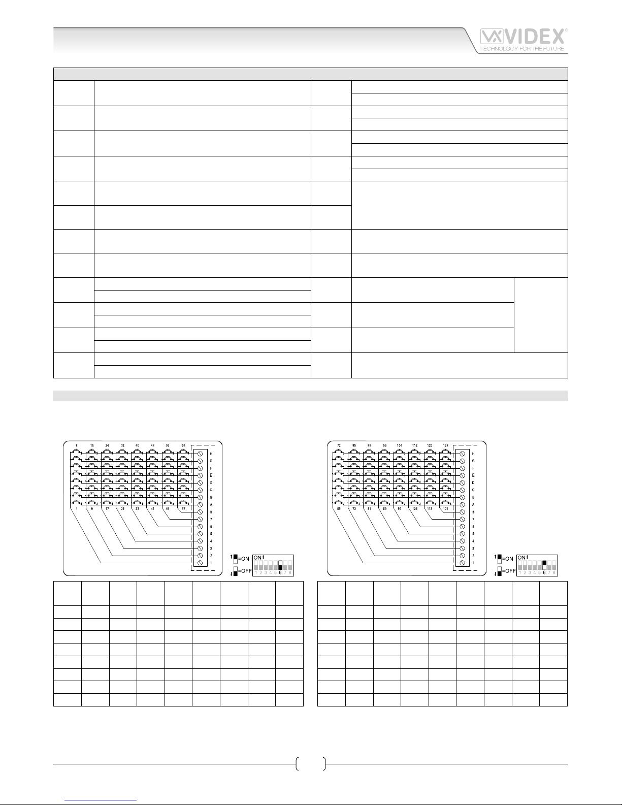
BUTTON MATRIX
The button, when pressed, will generate a call to a specic address according to the terminals to which the button is connected: i.e.
a button connected between terminals “2” and “B”, when pressed will generate a call to the address 10 if the dip-switch 6= OFF or a
call to the address 74 if the switch 6=ON.
SW6
OFF
1 2 3 4 5 6 7 8
A 1 9 17 25 33 41 49 57
B 2 10 18 26 34 42 50 58
C 3 11 19 27 35 43 51 59
D 4 12 20 28 36 44 52 60
E 5 13 21 29 37 45 53 61
F 6 14 22 30 38 46 54 62
G 7 15 23 31 39 47 55 63
H 8 16 24 32 40 48 56 64
SW6
ON
1 2 3 4 5 6 7 8
A 65 73 81 89 97 105 113 121
B 66 74 82 90 98 106 114 122
C 67 75 83 91 99 107 115 123
D 68 76 84 92 100 108 116 124
E 69 77 85 93 101 109 117 125
F 70 78 86 94 102 110 118 126
G 71 79 87 95 103 111 119 127
H 72 80 88 96 104 112 120 128
Art.4303N Speaker unit module with built-in functional to digital interface
Page 4

66251360-EN - V2.0 - 14/10/15
4
4000 Series
Art.4303N - Installation instructions
UNIT SPECIFICATION
Housing/Mounting: One 4000 Series Module / 4000 Series Modular System
Push Buttons: Yes, from 0 to 2 call buttons according to the model
Programming: Yes, carried out by the 8 way dip-switch located on the rear of the module
Controls: Microphone and Loudspeaker volume trimmers plus balance trimmer
Front plate nishes: Mirror stainless steel (standard), Anodized Aluminium (add /a after the product code) or High Brass (add /HB)
Power Supply: Supplied by the BUS line
Power consumption: Stand-by: 28mA
Operating: 38mA
Working Temperature: -10 +50 °C
Art.4303N Speaker unit module with built-in functional to digital interface
CUSTOMER SUPPORT
All Countries:
VIDEX ELECTRONICS S.P.A.
www.videx.it - technical@videx.it
Tel: +39 0734-631669
Fax: +39 0734-632475
UK Customers:
VIDEX SECURITY LTD
www.videx-security.com
Tech Line: 0191 224 3174
Fax: 0191 224 1559
The product is CE marked demonstrating its conformity and is for distribution within all member states of the EU with no restrictions. This product
follows the provisions of the European Directives 2004/108/ECC (EMC);
2006/95/ECC (LVD) and 93/68/ECC (CE marking).
Page 5

66251360-EN - V2.0 - 14/10/15
5
4000 Series
Art.4303N - Installation instructions
Art.4303N Speaker unit module with built-in functional to digital interface
Page 6

66251360-EN - V2.0 - 14/10/15
6
4000 Series
Art.4303N - Installation instructions
Art.4303N Speaker unit module with built-in functional to digital interface
Page 7

66251360-EN - V2.0 - 14/10/15
7
4000 Series
Art.4303N - Installation instructions
Art.4303N Speaker unit module with built-in functional to digital interface
Page 8

66251360-EN - V2.0 - 14/10/15
8
4000 Series
Art.4303N - Installation instructions
Art.4303N Speaker unit module with built-in functional to digital interface
 Loading...