

Page 1
4212 PC SOFTWARE
PROGRAMMING GUIDE
4212 PC SOFTWARE PROGRAMMING GUIDE EN-UK
V.1.0
17/09/15
WE RECOMMEND
This equipment be installed by a
Competent Electrician, Security
Installation or Communications Engineer.
Page 2

4212 PC SOFTWARE PROGRAMMING GUIDE
CONTENTS
INTRODUCTION 4
SOFTWARE INSTALLATION 4 - 5
• USB Driver Installation 4
• 2X00PC Software Installation 4 - 5
HARDWARE INSTALLATION 5 - 6
TERMINALS, JUMPERS AND SWITCHES 6
TECHNICAL SPECIFICATION 6
USING THE SOFTWARE 7 - 37
• Launching the Software 7
THE MAIN PROGRAMMER SCREEN 7
SETTINGS WINDOW 8 - 14
• Line 1, 2 and 3 Text Fields 8
• Screen Switch Time; Lock Time; Speech Time; Master Code; Admin Code; Trade Code and Setup 9
• Trade Features; Setting up a Trade button 10
• Speech Playback; Door No.; Language; Door Mode 11
• Master or Slave; Date Format; Mode; Security Level 12
• Wiegand Format; Fob Format; Prox Type; Set the Time and Date 13
• Check Time and Date; Direct Call; Home2 Present; RFID Enabled 14
APARTMENTS WINDOW 15 - 17
• Mem; Apt No.; Phone ID 15
• Block ID; Access Code; Name; Floor 16
• EN (enable/disable) 17
LOGO WINDOW 17 - 21
• Draw Icon 17
• Erase Icon; Draw Box Icon; Erase Box Icon; Import Image Icon 18
• Reverse Icon; Justify Image Icons; Text Icons 19
• Clear Icon; Vertical and Horizontal Adjustment Bars 20 - 21
CODED ACCESS WINDOW 21 - 23
• Mem; Name; Apt No; Access Code 22
• Enable; Clear 23
PROXIMITY ACCESS WINDOW 24 - 27
• Mem; Name 24
• Apt No.; Fob/Card Number; Understanding the Fob Format and Car Number 25
• Using the PROXE Deskmount Reader for Programming Fobs/Cards; Code 26
2
4212 PC Software Programming Guide EN-UK - V.1.0 - 17/09/15
Page 3

4212 PC SOFTWARE PROGRAMMING GUIDE
• Enable; Clear 27
CODE + FOB WINDOW 28
• Code and Fob Setup on the Code + Fob Window 28
PROGRAMMER SCREEN TOP MENU 28 - 36
• FILE 29 - 31
• New; Open; Open Recent 29
• Save; Save As; Print 30
• Exit 31
• SYSTEM 31
• DOWNLOAD 31 - 32
• Download All; Download Apartment & Settings; Download Codes; Download Prox;
Download Codes + Prox
• Download Logo 32
• UPLOAD 32 - 33
31
• Upload All; Upload Only Block; Upload Apartments & Settings; Upload Prox; Upload Code 32
• Upload Code + Prox; Upload Logo; Speed 33
• DOWNLOADING AND UPLOADING 33
• LANGUAGE 33
• AUTO FILL 33 - 35
• Apartment No.; Phone ID; Block ID 34
• Name; Floor 35
• COMMUNICATION 36
• Comm Port; Refresh List; Check Connection; Manually Connect 36
• BAUD 36
• ABOUT 36
PROGRAMMER SCREEN STATUS AND PROGRESS BAR 36- 38
• Not Detected 36
• Detected; Opened File; Saved File; Downloading Settings; Uploading Settings 37
• No Response 38
POWERING UP THE 4212 DIGITAL PANEL 38
CONNECTION DIAGRAM 39
QUICK SOFTWARE SETUP GUIDE 40
PROXE SETUP GUIDE 40
NOTES 40 - 42
SOFTWARE UPDATES 43
FIRMWARE UPDATES 43
3
Page 4
4212 PC SOFTWARE PROGRAMMING GUIDE
INTRODUCTION
This programming guide is intended to give an introduction on the additional programming features
found in the 2X00PC software (version 7.0.0.14 or later) for programming the 4212 series digital door
panel.
The connection to the device is via a micro USB cable between the PC and the 4212 panel. The
software can also be used to program both 2200 and 2300 digital panels as well as the UIM-138
display and voice annunciation module. For technical support using this program please call 0191
224 3174.
SOFTWARE INSTALLATION
First of all install the USB driver which can be found on the installation CD supplied.
USB Driver Installation
1. Insert the 2X00PC installation CD into the CD rom drive of the PC.
2. Select ‘RUN’ from the start menu.
3. Type in ‘D:\CDM20824_setup.exe’ then press the ‘OK’ button.
4. The relevant drivers for the USB cable will be installed.
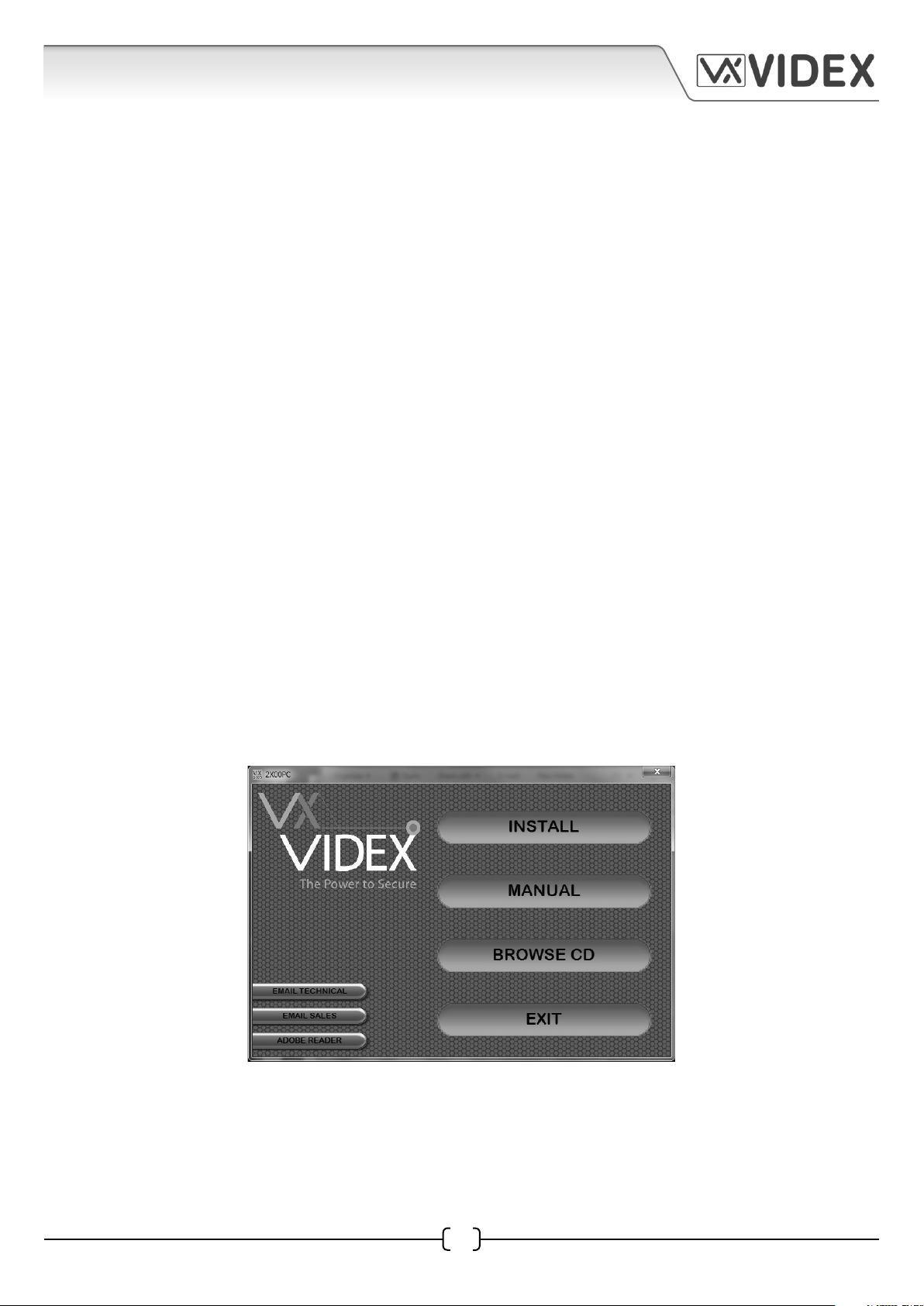
2X00PC Software Installation
1. Insert the 2X00PC installation CD into the CD rom drive of the PC.
2. Wait for the autorun to begin.
3. After a short while the following start up menu screen will appear.
From the start up menu screen the following options will be available:
4
EN-UK - V.1.0 - 17/09/154212 PC Software Programming Guide
Page 5
4212 PC SOFTWARE PROGRAMMING GUIDE
INSTALL : Installs the 2X00PC programming software on the PC.
MANUAL : View the pdf version of this PC Programming Guide.
BROWSE CD : Browse the installation CD for other files and programs.
EXIT : Exit out of the start up program.
EMAIL TECHNICAL : This will open your default email program so that you can send an email
to the Videx Technical Support.
EMAIL SALES : This will open your default email program so that you can send an email
to the Videx Sales Department.
ADOBE READER : If you do not already have a pdf reader to view the pdf version of the manual,
click this option to install a free pdf reader.
If the the autorun does not begin automatically, explore the CD and run the ‘autorun.
exe’ program.
Install the program to your PC by clicking on the INSTALL button from the start up
screen or alternatively browse the CD and select ‘setup.exe’ from the route of the CD.
The 2X00PC program will appear in your start menu and as a short cut to the desktop.
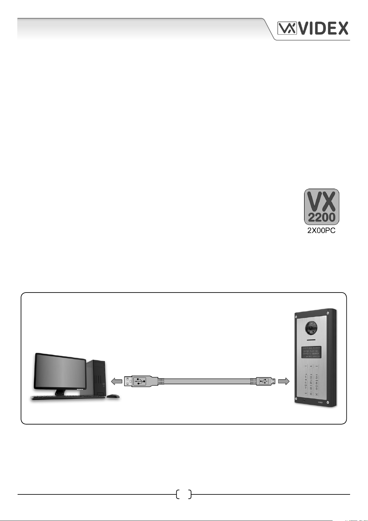
HARDWARE INSTALLATION
After the software is installed connect the 4212 digital panel to the PC using the USB cable as shown
in Fig.1A.
PC
USB to micro USB cable
Fig.1A
The USB cable should be connected into the 4212 digital panel and 12Vdc power connected as
shown in Fig.1B.
5
4212 PC Software Programming Guide EN-UK - V.1.0 - 17/09/15
4212 Digital Panel
Page 6
4212 PC SOFTWARE PROGRAMMING GUIDE
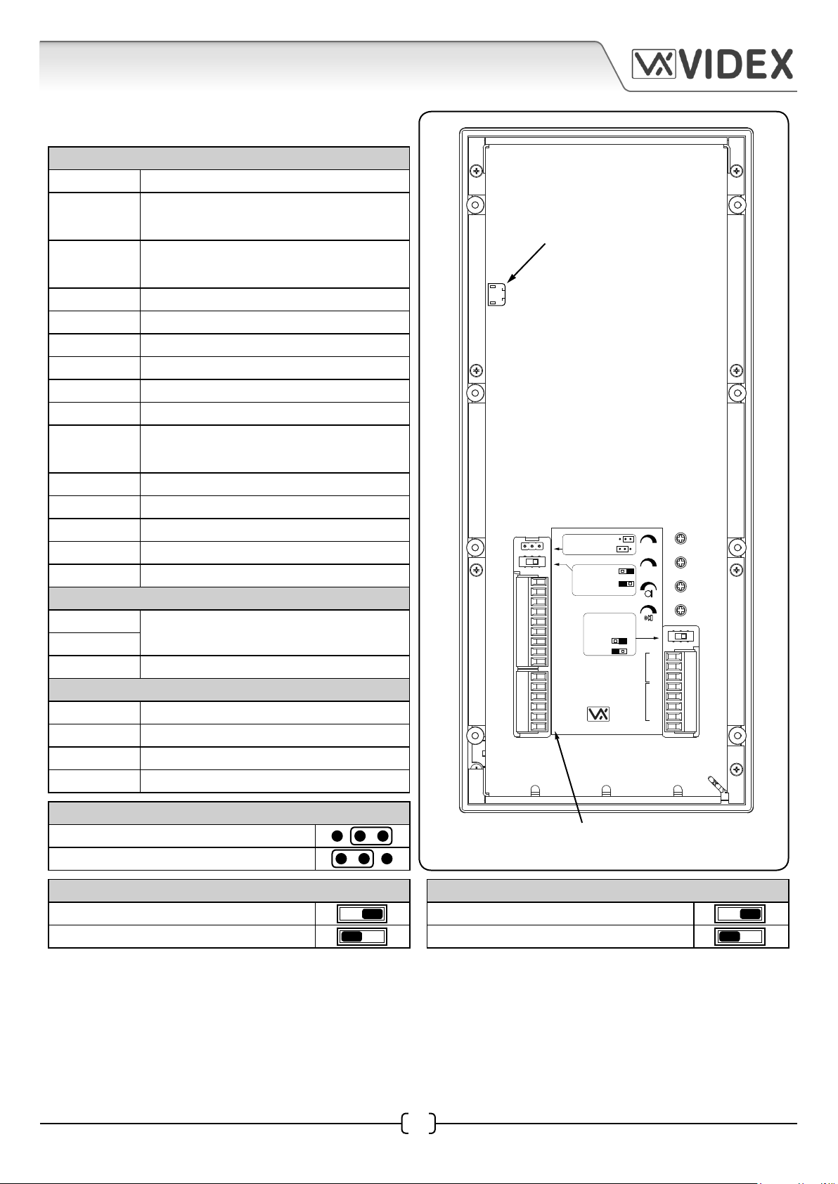
TERMINALS, JUMPERS AND SWITCHES
CONNECTION TERMINALS
12T +12Vdc camera power supply input.
GNDV
V2/V
0V camera power supply input and
video ground on coax video system.
Balanced video signal sync- (V2) or coax
video signal (V). Also see switches.
V1 Balanced video signal sync+ (V1).
PTE Push to exit input (switched 0V).
TRD Trade signal (from Art.701T).
NO Relay output - normally open contact.
C Relay output - common contact.
NC Relay output - normally closed contact.
SL
Accessory control signal (switched 0V
output).
BS Busy signal.
L Bus connection (positive).
- Bus connection (negative).
+12 +12Vdc power supply input.
OC OUTPUT Open collector output.
RS485 CONNECTION TERMINALS
A
RS485 serial bus interface.
B
GND Ground.
WIEGAND CONNECTION TERMINALS
D0 Data 0.
D1 Data 1.
LR Red ‘denied’ LED status output.
LG Green ‘granted’ LED status ouput.
4212 Digital Panel
connect the USB cable into the
the micro USB connection
USB
Dry contact output
Capacitor discharge
Balanced V1,V2
12T
Coax V2=V, V1
not used
GNDV
V2/V
V1
PTE
BUS TERMINATION
TRD
NO
C
NC
SL
BS
L
+12
GND
Made in Italy
Open
Close
RS485
RS485
WIEGAND
OC OUTPUT
V.P.B.CHIP
Balance
GND
A
B
D0
D1
LR
LG
JUMPERS
Dry contact output.
Capacitor discharge.
SWITCHES
Balanced V1, V2
Coax V2 = V, V1 not used.
Fig.1B
RS485 BUS TERMINATION
OPEN.
CLOSED.
TECHNICAL SPECIFICATION
Memory capacity: 998 users; 2800 key fobs; 2800 access codes
Working voltage: 12Vdc +/- 10%
Current Rating: approx. 350mA (max.)
Working Temperature: -10 to +50°
6
12Vdc power connected into
the +12/GND terminals
EN-UK - V.1.0 - 17/09/154212 PC Software Programming Guide
Page 7
4212 PC SOFTWARE PROGRAMMING GUIDE
USING THE SOFTWARE
Launching the Software
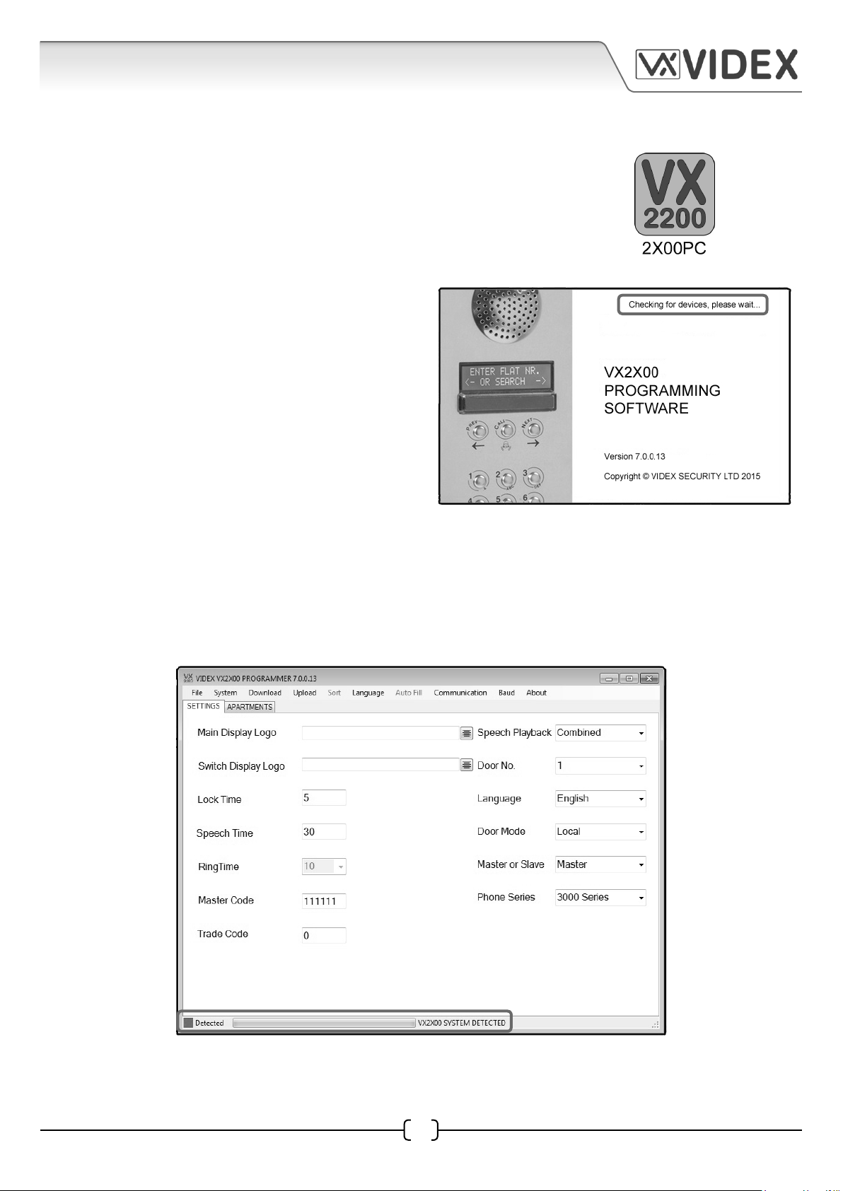
Launch the 2X00PC software by double clicking on the desktop icon.
The initial launch window will appear (as shown on
the right). At the top of the window the software
will show that it is checking for any devices
connected to the PC or laptop.
After a brief period the main programmer screen will appear.
THE MAIN PROGRAMMER SCREEN
If a device has been detected this will be shown at the bottom of the main programmer screen with
a green square (see below). On this screen several programming options can be selected.
The main programmer screen shows several menu options at the top and two selectable windows
on the main screen; ‘settings’ and ‘apartments’. The default window is the ‘settings’ tab.
4212 PC Software Programming Guide EN-UK - V.1.0 - 17/09/15
7
Page 8
4212 PC SOFTWARE PROGRAMMING GUIDE
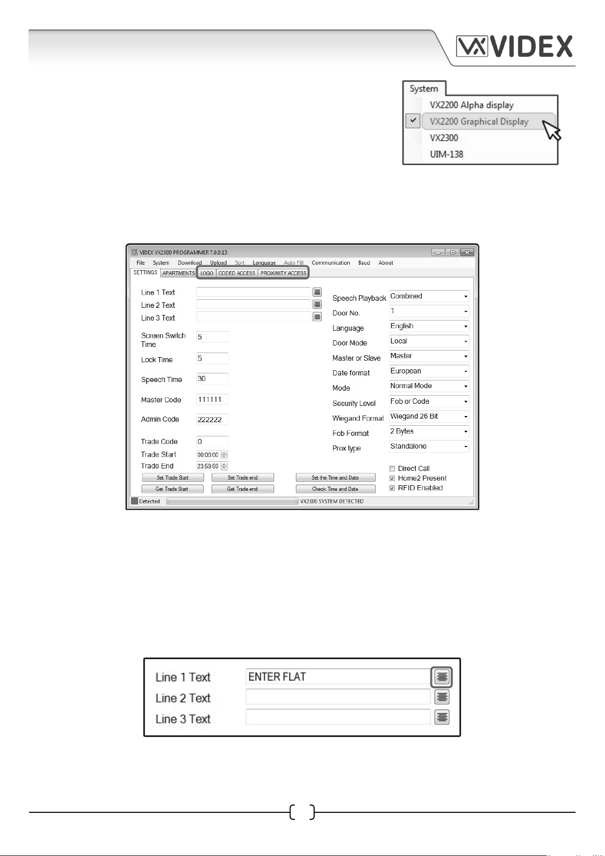
Before programming the 4212 digital panel the correct system
type must be selected from the top menu. To do this select
‘System’ from the top menu bar and then from the drop down
menu highlight and select ‘VX2200 Graphical Display’, (as shown
to the right).
Once the correct system type has been selected the ‘settings’ tab on the main programmer screen
will change appearance and include additional programming options. Three additional selectable
tabs will also appear; ‘logo’, ‘coded access’ and ‘proximity access’, as shown below.
SETTINGS WINDOW
Line 1, 2 and 3 Text Fields
In the top left corner of the ‘settings’ window there are three editable text line fields. Line 1 Text field
will have ‘ENTER FLAT’ set as the default text that will first appear on the 4212 digital panel when
powered up. The other two text fields will be blank. All three text lines can be edited if required and
the text can be centred in the middle of the 4212 display by clicking on the justify button to the right
of the text field (as shown below).
8
EN-UK - V.1.0 - 17/09/154212 PC Software Programming Guide
Page 9
4212 PC SOFTWARE PROGRAMMING GUIDE
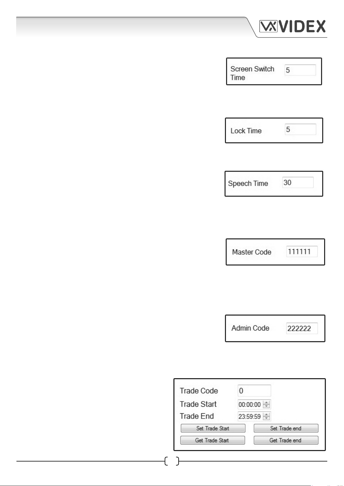
Screen Switch Time
Just below the three text line fields is the screen switch time field,
as shown on the right. This is the time (in seconds) that the main
display will switch between the three lines of text (entered in the
text fields) and a display logo. The default time is set for 5 seconds
(setting range from 1 - 255 seconds max.).
Lock Time
Below the screen switch time is the lock time field, as shown on
the right. This is the time (in seconds) that the relay on the 4212
digital panel will operate for. The default time is set for 5 seconds
(setting range from 1 - 255 seconds max.).
Speech Time
Below the lock time is the speech time field, as shown on the
right. This is the time (in seconds) that the speech conversation
time between the 4212 digital panel and intercom phone will
last for before automatically clearing down and ending the call.
The default time is set for 30 seconds (setting range from 30 - 255
seconds max.)
Master Code
Below the speech time is the master code field, as shown on the
right. This is the code used to access the programming features
when entering into the programming mode using the keypad on
the front of the 4212 digital panel when progamming the panel
manually. It is also the code used when uploading or downloading
data from the panel when using the PC programming software.
The default master code is set to ‘111111’ (6x1).
Admin Code
Below the master code is the admin code field, as shown on the
right. This code is used to allow users limited access to certain
programming features when programming the 4212 digital panel
manually (please also refer to technical programming document
‘66250203-EN’ for more information). The default admin code is
set to ‘222222’ (6x2).
Trade Code and Setup
Below the admin code is the trade code field
and the trade setup options, as shown to the
right. This allows the user to setup a trade code
(min 3 digits, max 6 digits) with start and end
times for the trade facility to work without the
need for a separate timeclock. The trade setup
functions are linked directly to the 4212 digital
panel’s relay. The start and end times can be set
4212 PC Software Programming Guide EN-UK - V.1.0 - 17/09/15
9
Page 10
4212 PC SOFTWARE PROGRAMMING GUIDE
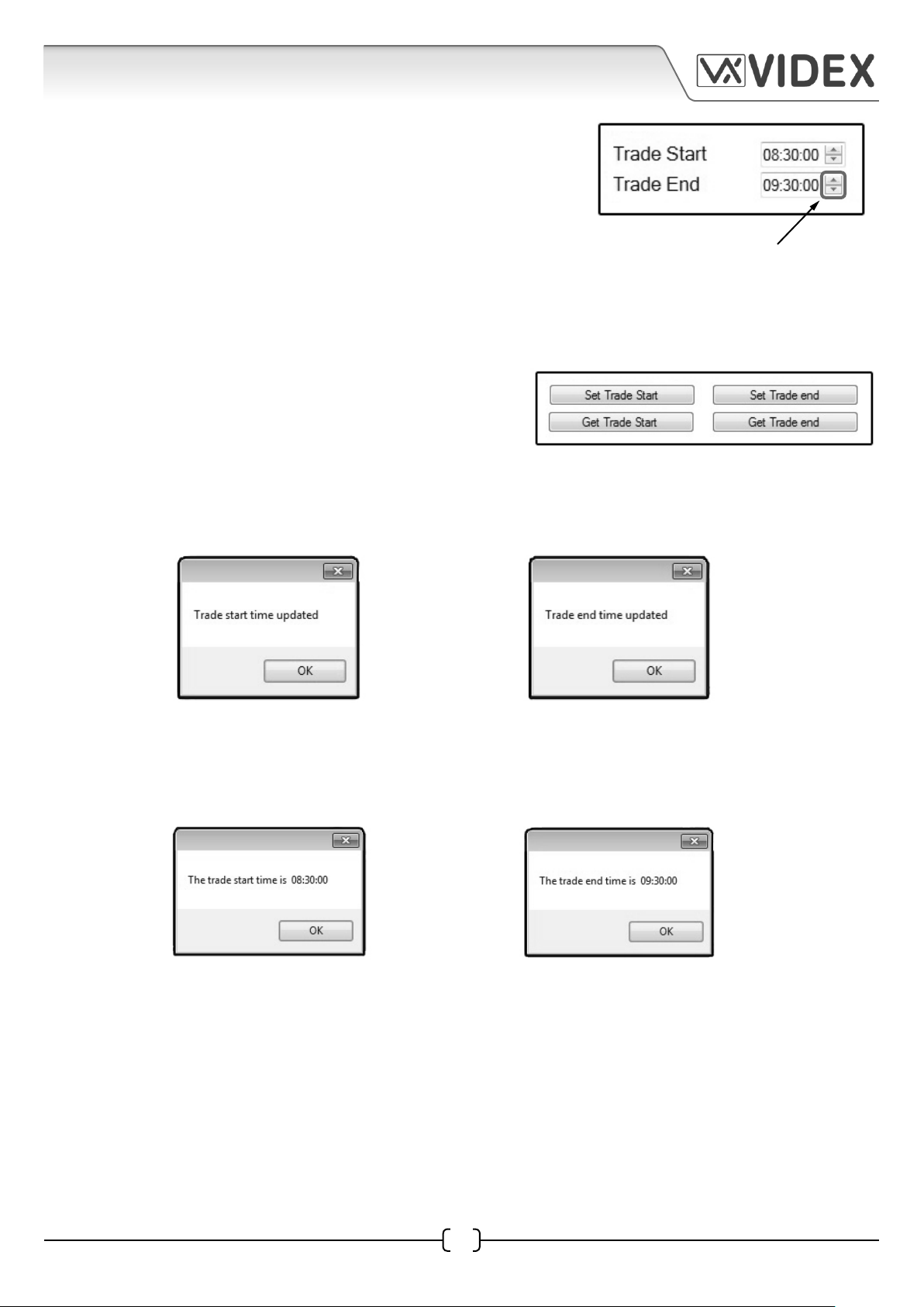
with the ‘trade start’ and ‘trade end’ fields using the up/down
(▲▼) scroll buttons to the right hand side of the respective
fields, as shown on the right, (the time format is hours: minutes:
seconds). When the trade times are set the trade code will only
operate the panel’s relay within these times and will operate
the relay for the lock time duration, (e.g. if the ‘trade start’ is set
to 08:30:00 and the ‘trade end’ is set to 09:30:00 with a lock time
set for 10, then the trade code will be ‘active’ for one hour between
8:30am - 9:30am and operate the panel’s relay for 10 seconds).
Trade Features
Below the trade time fields are four trade setup buttons;
set trade start, set trade end, get trade start and get
trade end, as shown on the right.
The set trade start and end buttons allow the engineer to set and update the trade start and end
times that have been entered in the trade time fields (refer to example above). Pressing the set trade
start button and pressing the set trade end button a confirmation window will appear (shown below).
▲▼ up/down scroll buttons
The get trade start and get trade end buttons allow the engineer to obtain the most recent trade
times that were set when the set trade start and set trade end buttons were last used (again refer to
example above). Pressing either of these buttons, the following confirmation windows will appear
(shown below) showing what start and end times were set.
Setting Up a Trade button
The 4212 panel can also be programmed to allow the ‘X’ button to function as a trade button if a
trade code is not required. To enable this feature through the software the trade code field should
be left blank. The trade start and end times will still need to be entered and the correct time and
date (refer to page 13) set on the 4212 panel (it should be noted that the 4212 panel can only operate
with a trade code or trade button not both).
10
EN-UK - V.1.0 - 17/09/154212 PC Software Programming Guide
Page 11
4212 PC SOFTWARE PROGRAMMING GUIDE
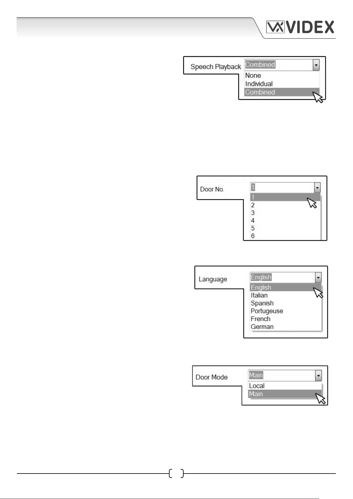
Speech Playback
In the top right corner of the ‘settings’ window is
the speech playback drop down menu with three
available options; None, Individual and Combined.
This setting is used to set the onboard speech
board in the 4212 digital panel. The default setting
is combined speech playback. By clicking on the
drop down menu button (▼) on the right of the eld this setting can be changed (if ‘none’ is selected
then there will be no speech playback when a call is made to the flat. If ‘individual’ is selected then the
speech annunciation will playback the individual numbers that make up the flat number e.g. if calling
flat 25 the speech will playback “calling two five”. If ‘combined’ is selected then the speech annunciation
will playback the combined flat number e.g. if calling flat number 15 the speech will playback “calling
fifteen”).
Door No.
Below the speech playback is the door number drop
down menu with up to 15 available door selections.
Use this menu to select and set the door number of
the 4212 digital panel (this feature is used on video
systems where the camera recall function is required
or on systems including a 2210 concierge and a panel
recall is required).
Language
Below the door number setting is the language
selection with 6 languages available; English
(default), Italian, Spanish, Portugeuse, French and
German. Use this menu to set the display language
on the 4212 digital panel (please note that this option
sets the display language on the 4212 digital panel
only and not the language of the PC programming
software).
Door Mode
Below the language setting is the door mode
selection. There are 2 door modes; LOCAL and MAIN.
(MAIN mode should only be used for 4212 panels that
call all users and on systems that include 2206N bus
exchange devices, LOCAL mode can be used for all
other applications. When using the 4212 panel in MAIN
mode, the programming of each user will require the address of the 2206N [block ID] for which that user
is connected. When this option is selected the block ID column on the ‘apartments’ tab will become
available to set the block ID. When in LOCAL mode the block ID column will not be available and will be
‘grayed out’. Also refer to block ID programming on page X).
4212 PC Software Programming Guide EN-UK - V.1.0 - 17/09/15
11
Page 12

4212 PC SOFTWARE PROGRAMMING GUIDE
Master or Slave
Below the door mode selection is the master or
slave drop down menu. Use this menu to set the
4212 panel as a master or slave panel.
Date Format
Below the master or slave setting is the date format
selection. Use this option to set the date format
shown in the top right corner of the display on the
4212 panel. The two options available are european
or american (when set to european the date format
will show the day: month: year and when set to american will show month: day: year).
Mode
Below the date format setting is the mode selection.
The two options available are normal mode or
compatibility mode. Normal mode enables all the
advanced features of the 4212 digital panel while
compatibility mode restricts features to those found
on older panels such as the 4202, SP30X and 8202
series.
Security Level
Below the mode setting is the security level drop
down menu. This setting allows the onboard relay
in the 4212 panel to be activated by using a door
access code or a proximity key fob or both (where
entering an access code as well as presenting a
proximity fob to the onboard reader is required to
activate the relay). The options available are fob or code or fob + code. If the fob or code option is
selected then a ‘coded access’ tab and a ‘proximity access’ tab will be shown at the top of the main
programmer screen if, however, the fob + code option is selected then the main programmer screen
will change appearance and show a combined ‘code + fob’ tab at the top of the screen (shown below).
12
EN-UK - V.1.0 - 17/09/154212 PC Software Programming Guide
Page 13
4212 PC SOFTWARE PROGRAMMING GUIDE
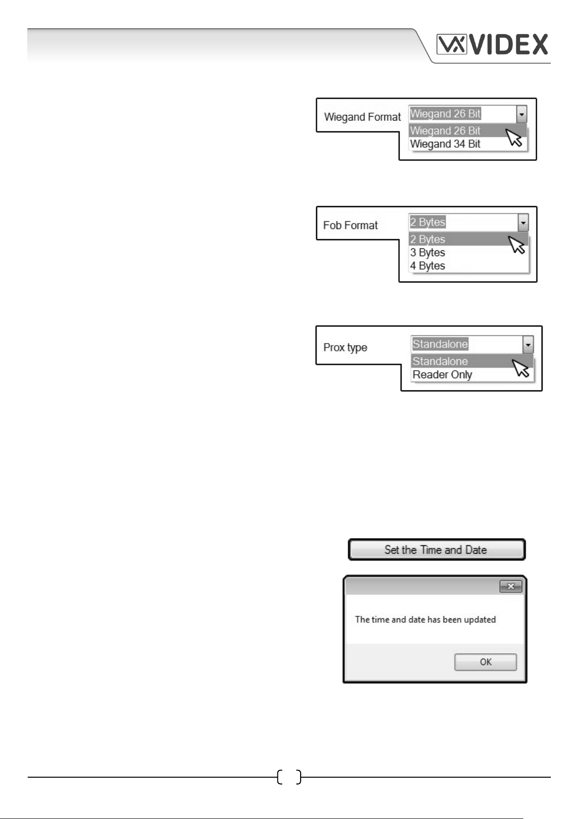
Wiegand Format
Next is the Wiegand format, as shown on the right.
From the drop down menu two Wiegand formats
are available; Wiegand 26 bit or Wiegand 34 bit.
The Wiegand format selection will depend on the
requirements of the external access control CPU and
is only relevant if an external controller is used.
Fob Format
Below the Wiegand format is the fob format, as
shown on the right. From the drop down menu 3
fob formats are available; 2 bytes, 3 bytes and 4
bytes. The fob format can only be set using the PC
programming software and sets the reading format
of the fob.
Prox Type
Next is the prox type. From the drop down menu
there are two selections; standalone and reader
only. These options set up the mode of the onboard
proximity reader. When in standalone mode the
programming of the key fobs is done using either
the PC programming software or via the 4212
panel itself going through the onboard menu selections. All the fob information is stored in the 4212
panel and there are no additional reader wiring connections to be made to an external controller.
When in reader only mode any key fob programming is done via an external proximity controller
that supports the Wiegand format (for example the Portal Plus proximity system or any other 3rd party
proximity control). If this option is selected all key fob data is held within the external controller
and not the 4212 panel, the reader in this instance is being used purely as a reader. Four additional
wiring connections will be required; D0, D1, LR, LG and a common 0V.
Set the Time and Date
Below the prox type is the ‘set the time and date’ button,
as shown on the right. Pressing this button will set the
time and date of the 4212 panel to the current time and
date of the PC. After the button is pressed a confirmation
window will appear, as shown below right. The format of
the date will be displayed in the date format (european
or american) that has been selected from the date format
drop down menu (refer to the date format on page 11).
4212 PC Software Programming Guide EN-UK - V.1.0 - 17/09/15
13
Page 14
4212 PC SOFTWARE PROGRAMMING GUIDE
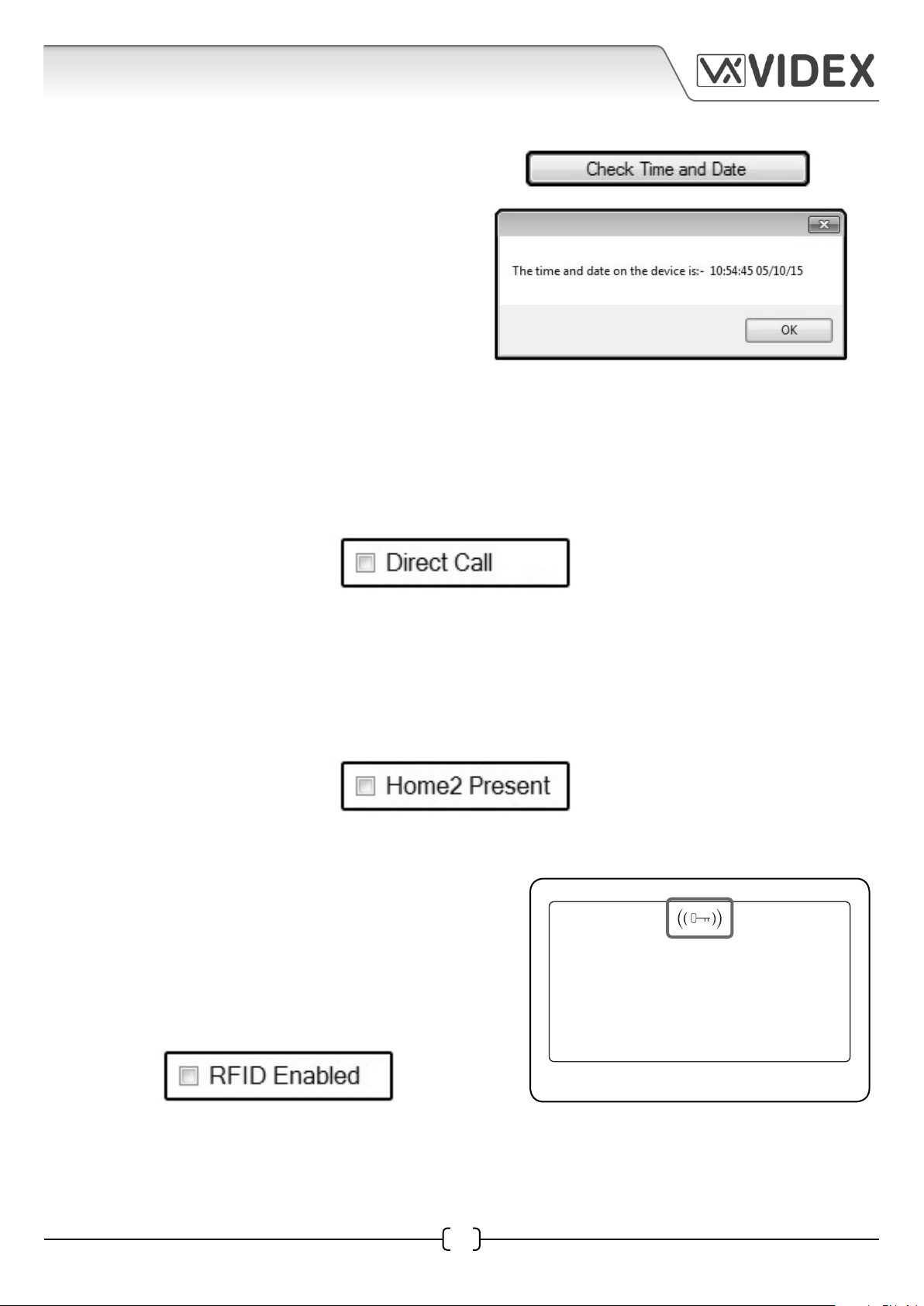
Check Time and Date
Below the set time and date button is the check
time and date button, as shown on the right.
Pressing this button will confirm the current time
and date setup on the 4212 panel. After pressing
this button a confirmation window will appear
showing the current time and date, as shown on
the right.
Direct Call
In the bottom right corner of the settings tab is the direct call check box, shown below. If this box is
ticked it will allow the numbered buttons (1-9) on the front of the 4212 panel to act like functional
call buttons (e.g. pressing button 1 will call phone ID.1, pressing button 2 will call phone ID.2 etc.). This
check box will be unticked as default and can only be set using the PC programming software.
Home2 Present
Below the direct call check box is the home2 present check box, shown below. If this box is ticked it
will allow the 4212 panel to switch between the lines of text (entered in Line 1, Line 2 and Line 3 text
fields) and logo screen (refer to pages 8 and 18 - 20). The timing of the transition between the display
text and logo will be based on the time set in the screen switch time field (refer to page 9).
RFID Enabled
Below the home2 present check box is the RFID enabled
check box, shown below. This check box enables or
disables the onboard proximity access reader within the
4212 panel. If this box is ticked it will enable the onboard
reader, this can be confirmed on the front display of the
4212 panel with a key symbol at the top centre of the
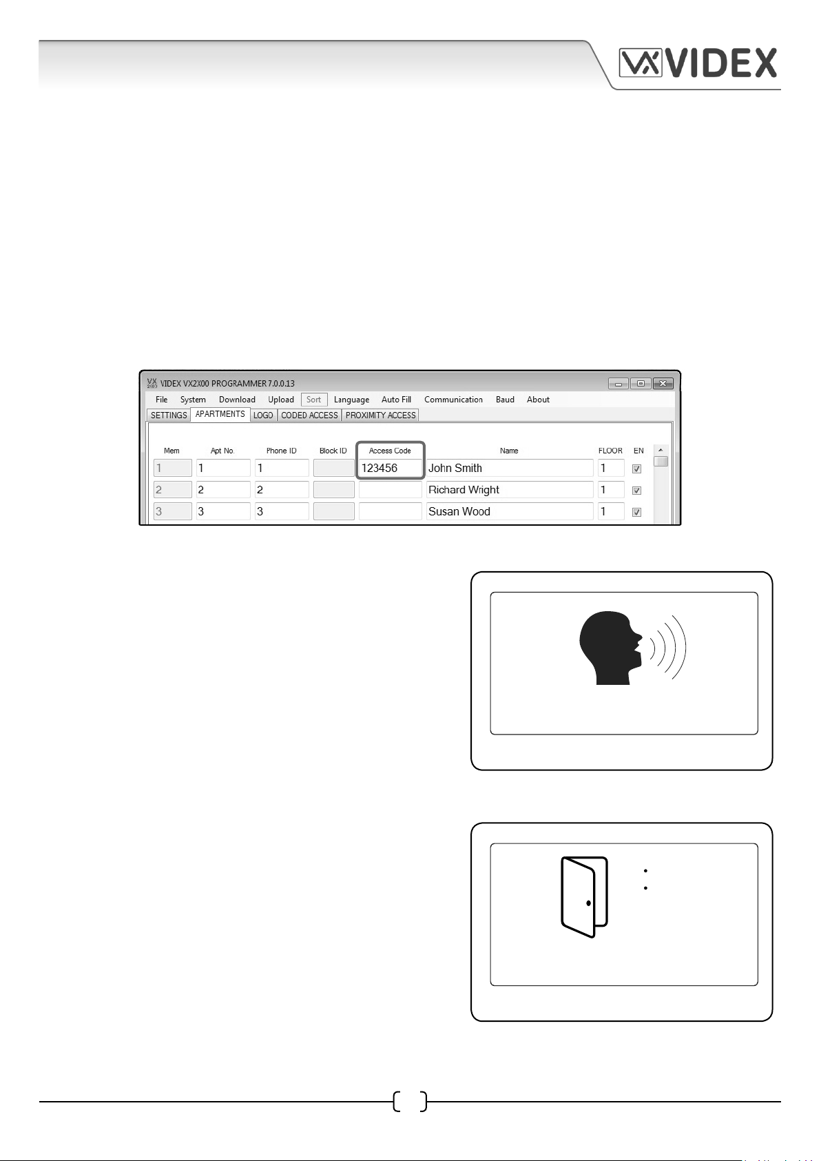
display, as shown in Fig.2.
12:05 05/10/15
Enter Flat No.
14
Fig.2
EN-UK - V.1.0 - 17/09/154212 PC Software Programming Guide
Page 15
4212 PC SOFTWARE PROGRAMMING GUIDE
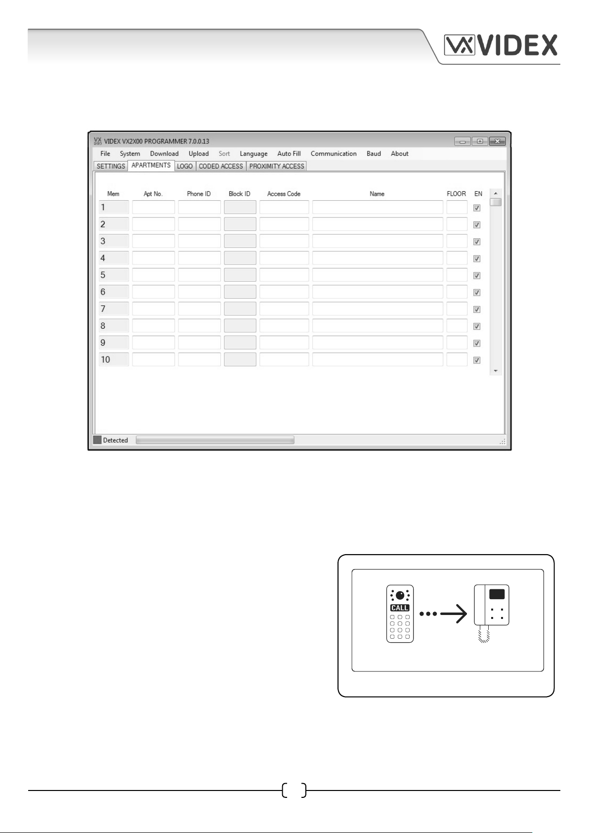
APARTMENTS WINDOW
The next tab on the main programmer screen is for the apartments window, as shown below.
Mem
This column is the memory location where the user’s data is stored in the 4212 digital panel. It is
already completed and ‘grayed’ out.
Apt No.
The user’s apartment number or flat number can be
entered into this field. The apartment number entered
into this field will be shown at the bottom of the display
(flashing between ‘calling’ and the user’s apartment
number) when a call is made to that apartment, as shown
in Fig.3, and is the number used to make a call.
calling
Fig.3
Phone ID
The address of the intercom phone in the user’s apartment can be entered into this field.
4212 PC Software Programming Guide EN-UK - V.1.0 - 17/09/15
15
Page 16
4212 PC SOFTWARE PROGRAMMING GUIDE
Block ID
By default this column will be ‘grayed’ out if the initial Door Mode setting in the settings window
is set to Local mode and therefore cannot be altered. If an Art.2206N bus exchange device is being
used, however, then the block ID can be entered into this field. (Information completed in this field
will only be applicable on multiple entrance systems where an Art.2206N bus exchange device has been
used and the Door Mode field in the settings window has been set to Main mode, also refer to page 10
regarding Door Mode setting).
Access Code
If a door access code is required it can be entered into this field. Each user can therefore have their
own access code, however if a single communal access code that all resisdents can share is required
then it can be entered into the first access code field only (in mem location 1 row, shown below).
Name
The name of the user, the apartment or the office name
can be entered into this field. The name entered into this
field will be displayed on the 4212 display once the call
from the intercom panel has been answered, just below
the speak icon, as shown in Fig.4, and is also the name
displayed when using the scroll facility.
Floor
The floor number for the apartment or the office can be
entered into this field. The floor number entered into
this field will be displayed on the 4212 display after a
call from the intercom panel has been answered and the
lock release button has been pressed on the intercom
phone. The floor number is shown just to the right hand
side of the door open icon on the display, as shown in
Fig.5.
Technical Dept.
Fig.4
No.:1
Floor:1
Door Opened
16
Fig.5
EN-UK - V.1.0 - 17/09/154212 PC Software Programming Guide
Page 17
4212 PC SOFTWARE PROGRAMMING GUIDE
EN (enable/disable)
Just to the right of the floor column is the EN check box
column. This check box can enable (ticked) or disable
(unticked) each individual line of programming. When
first opening the apartments window this column will
have all the check boxes ticked as default. If a line of
programming has this box unticked and an attempt is
made to call the flat or apartment from the intercom
panel the 4212 display will show ‘NOT FOUND’ as shown
in Fig.6. (Although the panel will show this message the
line of programming data is still held in the panel’s memory
Fig.6
and can be enabled again by either ticking the EN check
box in the PC software or entering the programming manually using the panel’s keypad and following
the on screen menu options).
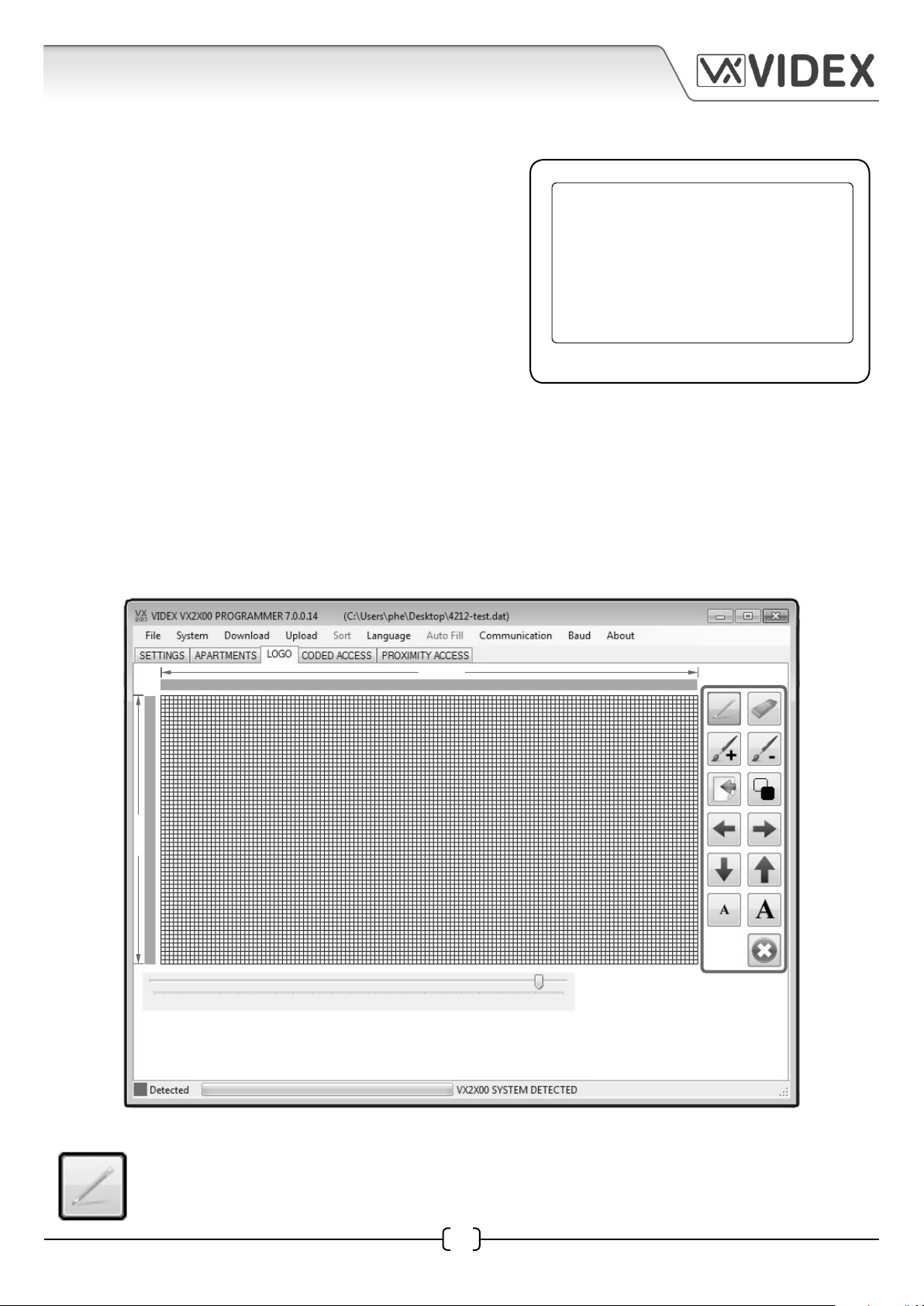
LOGO WINDOW
The next tab on the main programmer screen is for the logo window, as shown below, this can be
selected by clicking on the logo tab at the top of the screen. The main logo window consists of the
main editable 128x64 pixel area (the size of the main 4212 graphical display), vertical and horizontal
image adjustment bars and 13 edit icons down the right hand side, as shown below.
NOT FOUND
64 pixels
vertical adjustment bar
128 pixels
horizontal adjustment bar
Draw Icon
Selecting the draw icon on the right will allow the user to draw an image, logo or shape
by individual pixel.
17
4212 PC Software Programming Guide EN-UK - V.1.0 - 17/09/15
Page 18
4212 PC SOFTWARE PROGRAMMING GUIDE
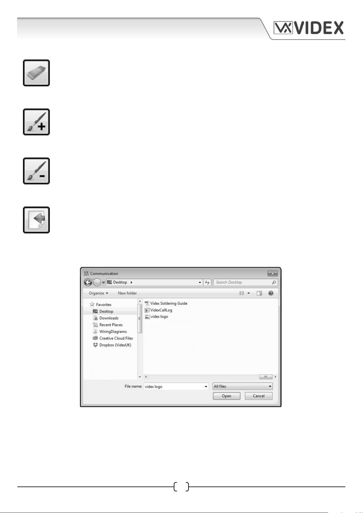
Erase Icon
Selecting the erase icon on the right will allow the user to erase individual pixels one at
a time.
Draw Box Icon
Selecting the draw box icon on the right will allow the user to draw an entire box larger
than an individual pixel (with no size contraints other than the size of the main 128x64
editing window itself).
Erase Box Icon
Selecting the erase box icon on the right will allow the user to delete an entire box area
larger than an individual pixel (with no size contraints other than the size of the main 128x64
editing window itself).
Import Image Icon
Selecting the import icon on the right will allow the engineer to import an image or logo
to use. Image file types that can be imported are: jpeg, png, bmp, gif and tiff.
Once the import icon has been selected the following communcation window will appear to find the
required image or logo file. Once the file has been located and selected click on the open button to
import the file.
Important Note: It may be necessary to scale down the image size to 128x64 pixels before importing
it into the logo editing window especially if it is a high resolution image. The reason for this is that
the detail in higher resolution images may be lost when importing. Any third party image software
(e.g. microsoft paint, adobe illustrator, coral draw or paintshop pro) can be used to do this. The 4212
graphical display and logo editing window is only designed to show and edit basic images and
company logos.
18
EN-UK - V.1.0 - 17/09/154212 PC Software Programming Guide
Page 19

TECHNICAL
DEPARTMENT
VIDEX
TECHNICAL
DEPARTMENT
VIDEX
4212 PC SOFTWARE PROGRAMMING GUIDE
Reverse Icon
Clicking on the reverse icon will change the appearance of the image or logo in the editing
area, any dark areas will become light and any light areas will become dark.
The image will appear like a photo negative in the editing area and on the main 4212 display. The
original image will appear as shown in Fig.7A with a dark background and light logo and text and if
the reverse icon is pressed it will appear as shown in Fig.7B with a light background and dark logo
and text.
Fig.7A Fig.7B
Justify Image Icons
Selecting and pressing on any of the justify image icons on the right will allow
the user to move the image or logo in the editing area left (), right (), down
() and up ().
Text Icons
There are two text icons. Selecting the text icon on the left will allow the user
to type in small text (upper or lowercase), selecting the text icon on the right
will allow the user to type in large text (upper or lowercase) to be shown on
the 4212 display.
Once a text icon has been selected move the cursor over to the left hand side of the editing area
(128x64 pixel area) and click. The following text window will appear, as shown on page 19.
Simply enter the required text in the text field and then click on the OK button. The text will appear in
the editing area. It should also be noted that the text font displayed is just a basic font. If a particular
font is required then it may be necessary to import this using the import icon (as mentioned on page
18), however, consideration should be taken into account when doing this because if the font is
quite intricate it may not display properly in the editing area and therefore will not show up properly
on the 4212 main display.
4212 PC Software Programming Guide EN-UK - V.1.0 - 17/09/15
19
Page 20
4212 PC SOFTWARE PROGRAMMING GUIDE
Clear Icon
Clicking on the clear icon will delete everything in the image editing area.
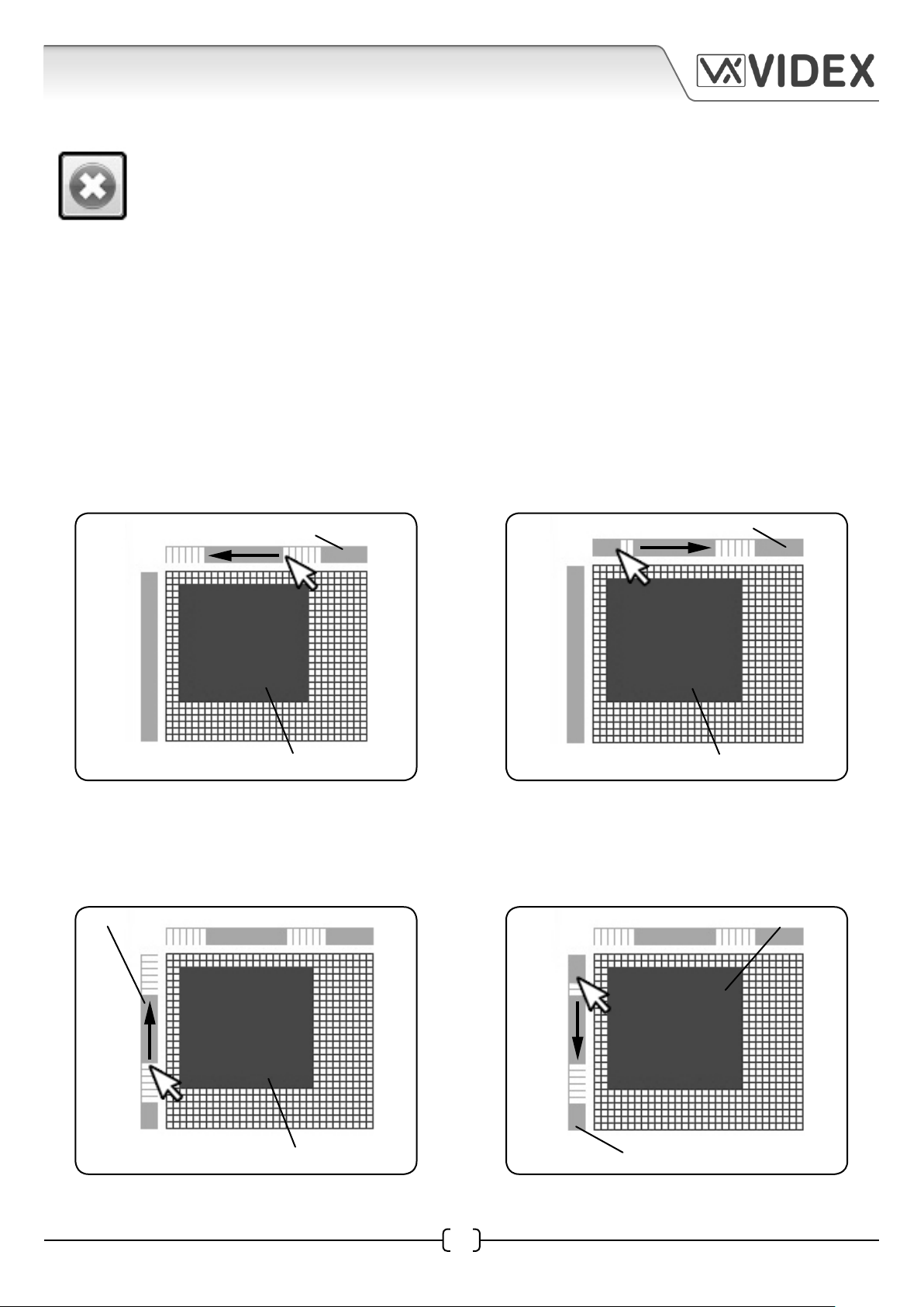
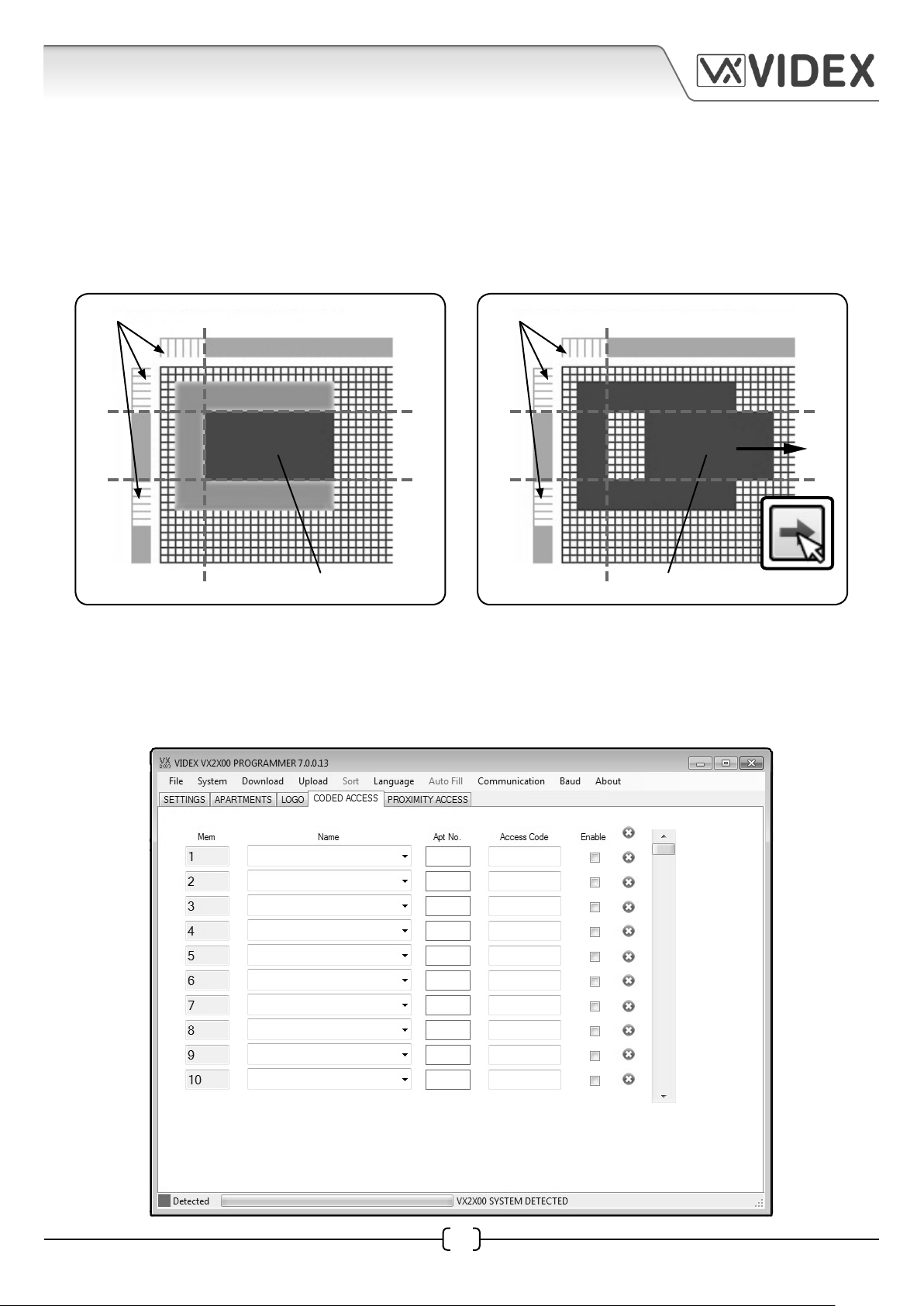
Vertical and Horizontal Adjustment Bars
The vertical and horizontal adjustment bars allow the user to select a specific region on the main
128x64 pixel editing area and move a specific image, part of an image or text within that specified
region by creating ‘pixel zones’. This is done by selecting individual pixels up and down the vertical
adjustment bar and/or selecting pixels along the horizontal adjustment bar.
To create a ‘pixel zone’ along the horizontal adjustment bar place the cursor on the top bar in the
area you wish to select. Click and hold down the left mouse button whilst moving the cursor left and
the individual pixels will highlight (in white) along the bar, as shown in Fig.8A. To de-select a ‘pixel
zone’ click and hold down the left mouse button whilst moving the cursor right and the individual
pixels will ‘gray out’ as the cursor is moved back along the bar, as shown in Fig.8B.
horizontal adjustment bar
image
Fig.8A
horizontal adjustment bar
image
Fig.8B
Creating ‘pixel zones’ along the vertical adjustment bar is done in a similar way. Click and hold down
the left mouse button whilst moving the cursor up the bar to highlight the pixels, as shown in Fig.9A.
To de-select a ‘pixel zone’ click and hold down the left mouse button but this time moving the cursor
down. The individual pixels will ‘gray out’ as the cursor is moved down the bar, as shown in Fig.9B.
vertictal adjustment bar
image
Fig.9A
image
20
Fig.9B
vertictal adjustment bar
EN-UK - V.1.0 - 17/09/154212 PC Software Programming Guide
Page 21
4212 PC SOFTWARE PROGRAMMING GUIDE
After a ‘pixel zone’ has been created along each adjustment bar (areas highlighted in white) any
image, part of an image or text that is within this region will be fixed in position. Any image, part
of an image or text that is not within this region (areas ‘grayed out’) can be moved using the four
justify image icons (as described on page 19). An example of this is shown in Fig.10A, the dashed lines
indicate the ‘pixel zone’ boundry where the image is fixed. Pressing the right justify icon will move
part of the image that is not within these boundaries across to the right of the editing area, as shown
in Fig.10B.
‘pixel zone’ where image is xed
Fig.10A
adjustable image area
‘pixel zone’ where image is xed
Fig.10B
adjustable image area
CODED ACCESS WINDOW
The next tab on the main programmer screen is for the coded access window, as shown below. The
coded access tab will only be available if the security level on the settings window was set to fob or
code from the drop down menu (refer to page 12).
4212 PC Software Programming Guide EN-UK - V.1.0 - 17/09/15
21
Page 22
4212 PC SOFTWARE PROGRAMMING GUIDE
Mem
Like on the apartments window this column is the memory location where the user’s data is stored
in the 4212 digital panel. It is already completed and ‘grayed’ out.
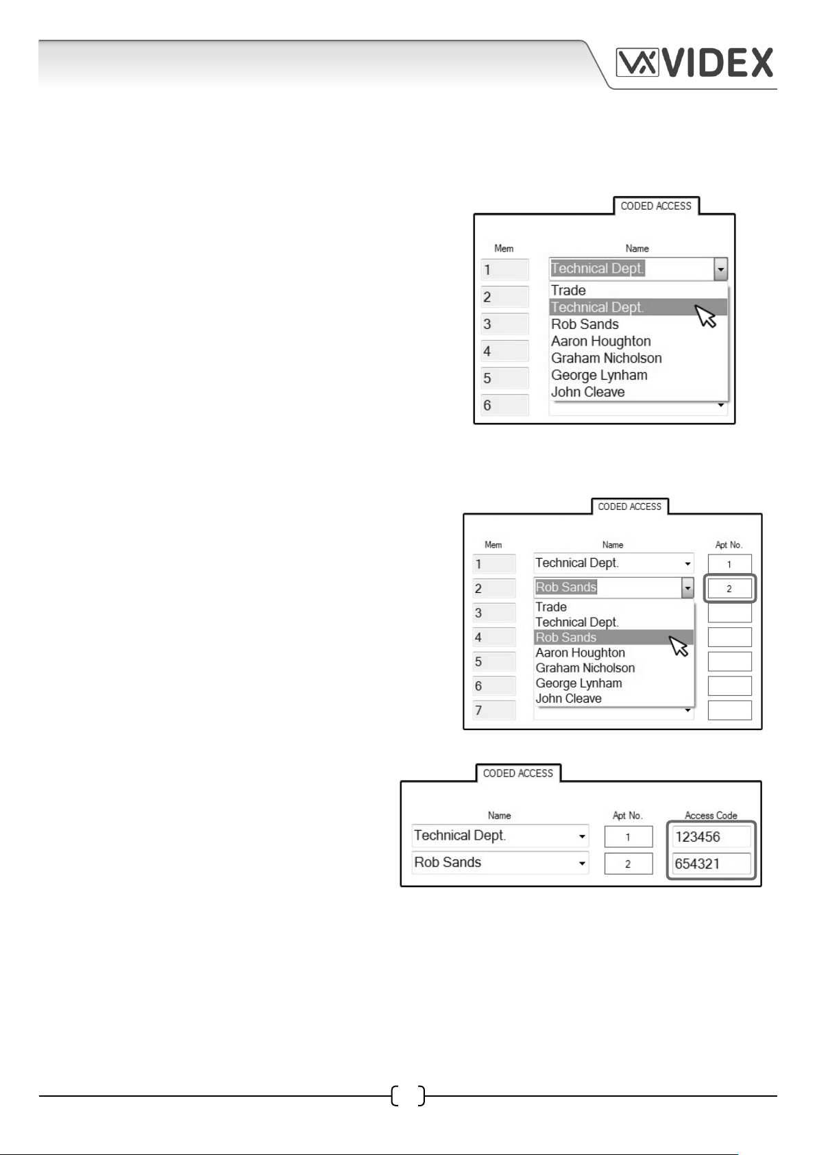
Name
The name column for each memory location row has
a drop down menu where an optional trade code or
user’s name can be selected, as shown on the right.
The list of names shown in this drop down menu is
taken directly from the name column shown in the
apartments window (refer to pages 15 and 16). If Trade
codes or access codes are required that are only to
operate within the timeband (trade start and trade
end times) set in the trade code setup (refer to pages
9 and 10) then ‘Trade’ can be selected from the drop
down list. An access code can then be entered in the
‘Access Code’ field and then enabled by checking the
‘EN’ enable check box (refer to page 23).
Apt No.
Next is the Apt No. column and the apartment
information in this field will appear once a name
has been selected from the drop down menu in the
name column, as shown on the right. The apartment
information is taken from apartment number that
was entered in the Apt No. column in the apartments
window (refer to pages 15 and 16).
Access Code
Next is the Access Code column and this is
where the access code can be entered, as
shown on the right. If each user requires their
own access code it can be entered into this
field, however, if a single communal access
code is required that is shared by all users
then it only needs to be entered into the first access code field in mem location 1.
4212 PC Software Programming Guide EN-UK - V.1.0 - 17/09/15
22
Page 23
4212 PC SOFTWARE PROGRAMMING GUIDE
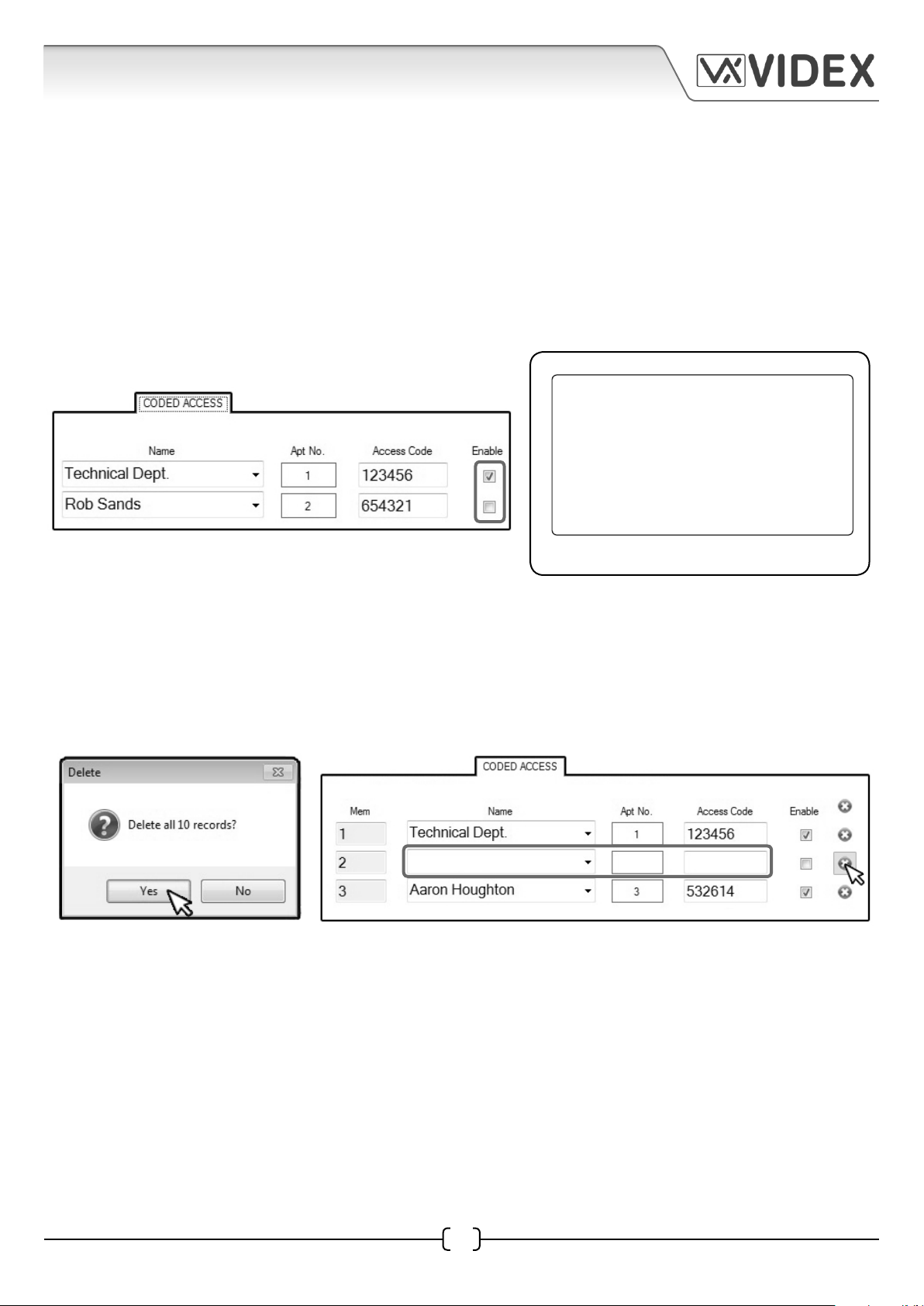
Enable
The enable check box column is next. The enable check box on each row of data will enable or
disable the individual user’s access code, as shown below. If the check box is ticked it will enable
the user’s access code, and if left unticked will disable the user’s access code. If the check box is
unticked, but the user has an access code in the access code column the code itself will still be stored
in the memory of the 4212 panel after an upload. If an attempt is made to use the access code via the
keypad on the 4212 panel then the display will show ‘NOT ALLOWED’, as shown in Fig.11. The access
code can be enabled again manually through the 4212 keypad following the onboard programming
menu (please also refer to technical programming document ‘66250203-EN’ for more information).
NOT ALLOWED
Fig.11
Clear
The last column on the coded access window is the clear symbol column. If the clear symbol in the
top right corner is pressed then a delete window will appear. Clicking on the YES button, as shown
below left, will then clear all data (up to 10 rows that are displayed) on the coded access window. If
the clear symbol on an individual row is pressed then it will only clear the data for that row, as shown
below right.
23
EN-UK - V.1.0 - 17/09/154212 PC Software Programming Guide
Page 24
4212 PC SOFTWARE PROGRAMMING GUIDE
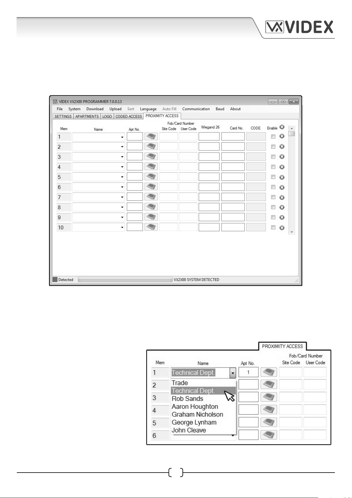
PROXIMITY ACCESS WINDOW
The next tab on the main programmer screen is the proximity access window, as shown below. The
proximity access tab will only be available if the security level on the settings window was set to ‘fob
or code’ from the drop down menu (refer to page 12).
Mem
Like on the apartments window and coded access window this column is the memory location where
the user’s data is stored in the 4212 digital panel. It is already completed and ‘grayed’ out.
Name
The name column for each memory
location row has a drop down menu
where an optional trade key fob
or user’s name can be selected, as
shown on the right. The list of names
shown in this drop down menu is
taken directly from the name column
shown in the apartments window
(refer to pages 15 and 16).
4212 PC Software Programming Guide EN-UK - V.1.0 - 17/09/15
24
Page 25
4212 PC SOFTWARE PROGRAMMING GUIDE
Apt No.
Next is the Apt No. column and like on the coded access window the apartment information in this
field will appear once a name has been selected from the drop down menu in the name column.
Again the apartment information is taken from apartment number that was entered in the Apt No.
column in the apartments window (refer to pages 15 and 16).
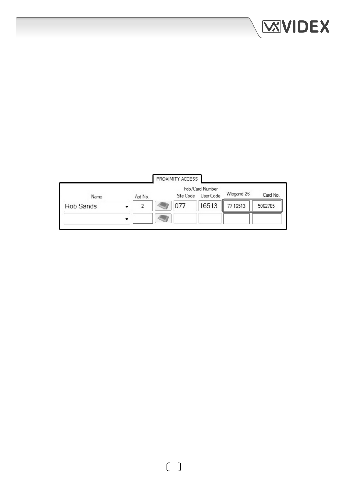
Fob/Card Number (Site Code, User Code, Wiegand 26 and Card No.)
The next four columns are site code, user code, Wiegand 26 and card no. which make up the Fob/
Card Number details. The fob number on a proximity key fob (PBX1E) or card (PBX2) can be broken
down into two parts. The first 3 digit number on the fob/card is the site code and can be entered
into the site code field and the 5 digit number on the fob/card is the user code and can be entered
into the user code. When these details are entered into these fields the Wiegand 26 and card no.
fields will automatically be updated with the card’s Wiegand number and card number respectively,
as shown below.
Understanding the Fob Format and Card Number
It is important to understand the relationship between the fob format and the card number when
entering the card’s site code and user code into the appropriate fields.
• Fobs/Cards with 5 digit number (user code)
If a proximity fob/card has no site code but a 5 digit user code (955/T or 955/C) then the fob
format should be set to 2 bytes in the fob format field in the settings tab.
• Fobs/Cards with 3 digit site code and 5 digit user code
If using a fob/card with a 3 digit site code and 5 digit user code (see above ref: PBX1E or PBX2)
then the fob format should be set to 3 bytes.
• Fobs/Cards with longer site and user codes and the PROXE
If the fob/card has a longer site code and user code then the fob format should be set to 4
bytes. If using the PROXE deskmount reader for programming fobs and/or cards (refer to page
25 for PROXE programming) then the fob format should be set to 4 bytes.
25
EN-UK - V.1.0 - 17/09/154212 PC Software Programming Guide
Page 26

4212 PC SOFTWARE PROGRAMMING GUIDE
Using the PROXE Deskmount Reader for Programming Fobs/Cards
When programming with a PROXE deskmount reader the PROXE icon column in the proximity access
tab will be highlighted, as shown below.
Before using the PROXE deskmount reader to program fobs/cards ensure that it has been setup
correctly (refer to page 39 for PROXE setup). Also make sure that the fob format (refer to pages 13 and
24) has been set to 4 bytes (regardless of which type of fobs/cards are being used). Follow the steps
below to program a fob/card:
1. First select the user name from the ‘Name’ drop down list.
2. Click on the deskmount reader icon next to the Apt No. field as shown below.
At the bottom of the proximity access screen the following message will appear ‘PRESENT
THE CARD OR FOB’, as shown below. Also the green LED on the PROXE reader will come ON.
3. Present the fob/card to the reader. The reader will emit a beep and the green LED will go OFF.
4. The fob /card number fields (site code, user code, Wiegand 26 and Card No.) will automatically
update, as shown below. Simply repeat these steps for adding more fobs/cards.
Code
The Code column is next and will be ‘grayed’ out and is not applicable if only proximity fobs/cards
are being programmed.
4212 PC Software Programming Guide EN-UK - V.1.0 - 17/09/15
26
Page 27
4212 PC SOFTWARE PROGRAMMING GUIDE
Enable
The enable check box column is next. The enable check box on each row of data will enable or
disable the individual user’s key fob or card, as shown below. If the check box is ticked it will enable
the user’s key fob or card, and if left unticked will disable the user’s key fob or card. If the check box is
unticked, but the user has a key/card number data in the relevant columns then this data will still be
stored in the memory of the 4212 panel after an upload. If a fob or card is presented to the onboard
reader on the 4212 panel then the display will show ‘NOT ALLOWED’, as shown in Fig.12. The fob or
card can be enabled again manually through the 4212 keypad following the onboard programming
menu (please also refer to technical programming document ‘66250203-EN’ for more information).
NOT ALLOWED
Fig.12
Clear
The last column on the proximity access window is the clear symbol
column. If the clear symbol in the top right corner is pressed then a
delete window will appear. Clicking on the YES button, as shown on
the right, will then clear all data (up to 10 rows that are displayed) on
the proximity access window. If the clear symbol on an individual
row is pressed then it will only clear the data for that row, as shown
below.
4212 PC Software Programming Guide EN-UK - V.1.0 - 17/09/15
27
Page 28

4212 PC SOFTWARE PROGRAMMING GUIDE
CODE + FOB WINDOW
The code + fob tab will only appear at the top of the main programmer screen if the code + fob option
was selected from the security level drop down menu on the settings window (refer to security level
selection on page 12).
Code and Fob setup on the Code + Fob Window
The memory location column is already completed and ‘grayed’ out like on previous programming
windows. All other programming fields are setup in the same way as if you were programming an
access code and programming a proximity fob/card (refer to pages 21 - 23 for programming an access
code and pages 24 - 27 for programming a fob/card).
Important Note: It is important that when programming an access code to work in combination
with a fob/card that the access code entered in the code column in apartments window matches
the same access code entered in the code column in the code + fob window. If they do not match
then the 4212 panel will display ‘NOT ALLOWED’ when the code is entered. Also it is advised when
uploading the data back into the panel that the upload all option is selected from the upload drop
down menu.
PROGRAMMER SCREEN TOP MENU
At the top of the main programmer screen there are 10 menu options: File, System, Download,
Upload, Sort, Language, Auto Fill, Communication, Baud and About. The Sort and Auto Fill options
are initially ‘grayed’ out for the 4212 panel, as shown at the top of page 29. Once the apartments tab
is selected the Auto Fill menu option becomes available, as shown at the top of page 29.
28
EN-UK - V.1.0 - 17/09/154212 PC Software Programming Guide
Page 29
4212 PC SOFTWARE PROGRAMMING GUIDE
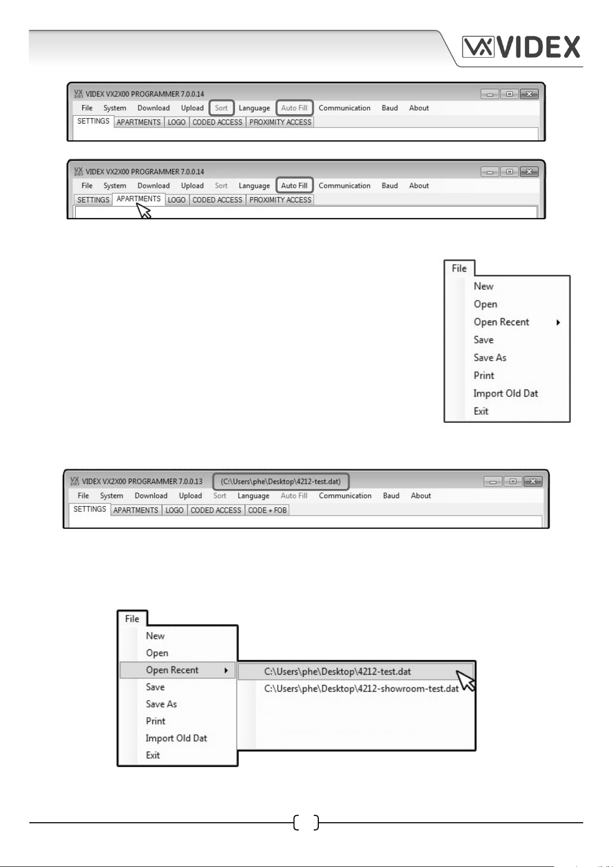
FILE
From the top menu on the main programmer screen when File is
selected the following drop down menu will appear, as shown to the
right, and the following options are available; New, Open, Open Recent,
Save, Save As, Print, Import Old Dat and Exit. The Open Recent option
expands to show a drop down list of the most recent files that have
been opened.
• New - selecting this option from the drop down menu will allow a
new database file to be created and saved.
• Open - selecting this option from the drop down menu will open an
existing database le that has previously been saved. (The le path
location and le name will be shown at the top of the programmer screen,
see below).
• Open Recent u - Select this option from the drop down menu, as shown below, and a list of the
most recent database files that were previously accessed will be shown. To open select and click
on the file required and the programming tabs will update with all file information.
4212 PC Software Programming Guide EN-UK - V.1.0 - 17/09/15
29
Page 30

4212 PC SOFTWARE PROGRAMMING GUIDE
• Save - select this option from the drop down menu to save the database file that is open.
• Save As - select this option from the drop down menu to save the database file in a specific file
location (a specified file path and location can be selected as shown below).
• Print - select this option from the drop down menu to print out the settings and the database
file, as shown below.
30
EN-UK - V.1.0 - 17/09/154212 PC Software Programming Guide
Page 31
4212 PC SOFTWARE PROGRAMMING GUIDE
• Exit - select this option when all programming is finished and exiting out of the programmer
software. (please note that when exiting out of the programmer software a prompt window will
appear asking if you want to save the current file before exiting, click on the required button. If saving
the file again it will be saved in the same file location as described under the Save As function).
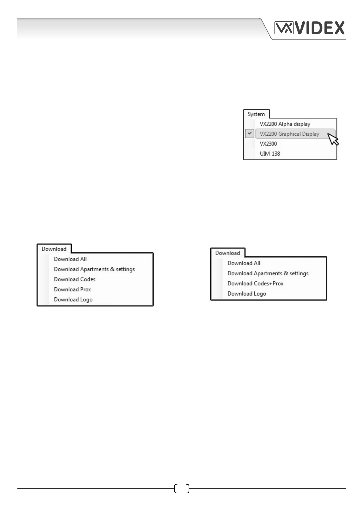
SYSTEM
From the top menu on the main programmer screen when system
is selected the following drop down menu will appear as shown
on the right. Although there are four options shown in the drop
down list, the VX2200 Graphical Display should be selected as a
4212 digital panel is being used. The other three options will not
be applicable.
DOWNLOAD
From the top menu on the main programmer screen when download is selected then one of two
drop down menus will appear. In the settings window if the ‘Code or Fob’ option was set in the
security level menu then the download drop down menu, as shown below left, will appear. If the
‘Code + Fob’ option was set instead then the download drop down menu, as shown below right, will
appear.
The menu options available; Download All, Download Apartments & Settings, Download Codes and
Download Prox or Download Codes+Prox and Download Logo.
• Download All - select this option from the drop down menu to download all settings, codes,
proximity fobs and any logo stored on the 4212 digital panel.
• Download Apartments & Settings - select this option from the drop down menu to download
the apartment programming stored on the 4212 digital panel; Apt No., Phone ID, Block ID (if
applicable), Access Code, Name and Floor number.
• Download Codes - (if the security level has been set to Fob or Code) select this option to download
all coded access programming stored on the 4212 digital panel.
• Download Prox - (if the security level has been set to Fob or Code) select this option to download
all proximity fob/card programming stored on the 4212 digital panel.
• Download Codes + Prox - (if the security level has been set to Code + Fob) select this option to
download all coded access and fob/card proximity programming stored on the 4212 digital
panel.
4212 PC Software Programming Guide EN-UK - V.1.0 - 17/09/15
31
Page 32
4212 PC SOFTWARE PROGRAMMING GUIDE
• Download Logo - select this option to download any logo stored on the 4212 digital panel.
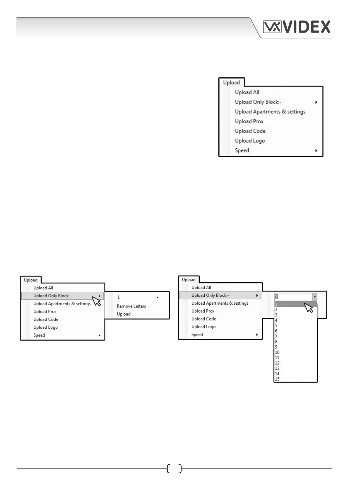
UPLOAD
From the top menu on the main programmer screen when
upload is selected the following drop down menu will
appear, as shown on the right. The following menu options
are available; Upload All, Upload Only Block, Upload
Apartment & Settings, Upload Prox, Upload Code, (if the
security level has been set to Code + Fob) Upload Code + Prox,
Upload Logo and Speed.
• Upload All - select this option to upload all programming including all settings, apartment
information, logo, coded access and proximity access to the 4212 digital panel.
• Upload Only Block - select this option to upload all programming for a specific block including
any coded access and proximity access (this option is only applicable if the 4212 digital panel is
set in main mode and 2206N bus exchange devices are being used, also refer to Door Mode setting
on page 11 and Block ID setting on page 16). Once selected an additional drop down menu will
appear as shown below left with 3 options. The first option is a further drop down list from 1 - 15
representing the Block ID’s, as shown below right. Next is the Remove Letters option, this will
remove any letters that may make up an apartment number when uploaded to the panel (e.g.
Apt No. 100A will become Apt No. 100 where the suffix A has been removed after an upload). Last on
the list is the Upload option to upload the information for the particular block to the panel.
• Upload Apartments & Settings - select this option to upload the apartment and settings
information only to the 4212 digital panel.
• Upload Prox - select this option to upload any proximity access information only to the 4212
digital panel.
• Upload Code - select this option to upload any coded access information only to the 4212 digital
panel.
32
EN-UK - V.1.0 - 17/09/154212 PC Software Programming Guide
Page 33

4212 PC SOFTWARE PROGRAMMING GUIDE
• Upload Code + Prox - if the security level has been
set to Code + Fob then the Upload Code + Fob option
will appear on the drop down menu as shown on the
right (refer to page 12 for security level setup). Select this
option to upload the coded access and proximity access
information only to the 4212 digital panel.
• Upload Logo - select this option to upload a company logo or image (refer to pages 17 - 21 for
logo setup) to the 4212 digital panel.
• Speed - last on the Upload drop down menu is the upload speed, when selected from the list a
further drop down list is available to set the speed (from 1 - 9, with 1 being the max. speed setting)
of the upload to the 4212 digital panel.
DOWNLOADING AND UPLOADING
Whenever a download or an upload is performed the master code window will appear, as shown
below. To download or upload enter the master code into the master code field and click on the start
button, otherwise click on the cancel button to cancel the download or upload.
LANGUAGE
Next from the top menu on the main programmer screen is the Language, this is the language used
for the PC programming software and is already default as english.
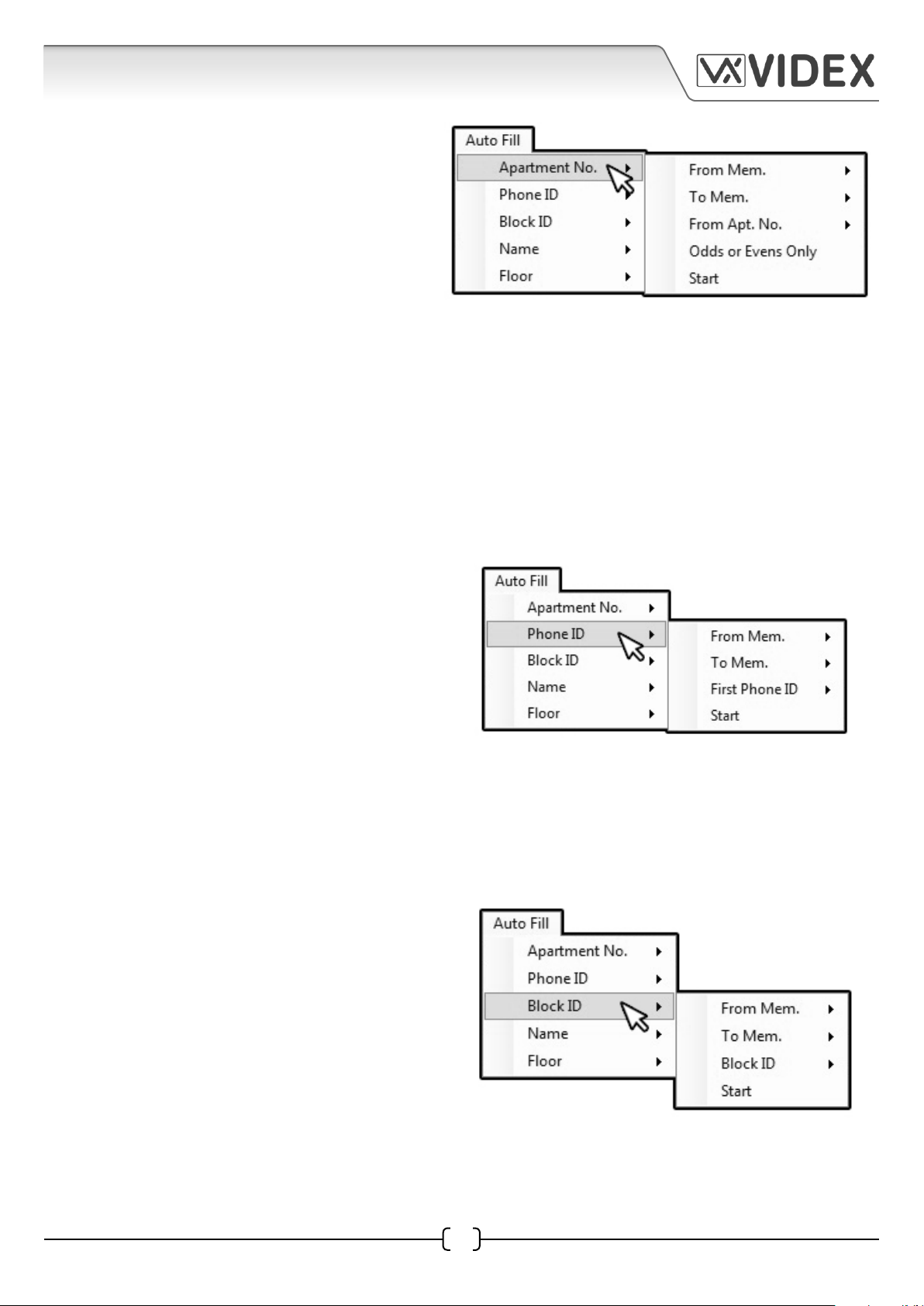
AUTO FILL
The Auto Fill menu option only becomes available when the
apartments tab has been selected (previously mentioned on page
28). Selecting this drop down menu will show four additional
options; Apartment No., Phone ID, Block ID and Name (four of the
programming columns in the apartments window), as shown on the
right. Each option has a further drop down list. Specific parameters
can be set that will allow the software to automatically input the
programming information required for the 4212 panel into the
relevant column.
4212 PC Software Programming Guide EN-UK - V.1.0 - 17/09/15
33
Page 34
4212 PC SOFTWARE PROGRAMMING GUIDE
• Apartment No. - select this option from the
drop down menu, as shown to the right,
to set the auto fill parameters (From Mem;
To Mem; From Apt No.; Odds or Evens Only
and Start) to input the apartment number
programming in the Apt No. column.
• From Mem - is the first memory location where the apartment information will be stored.
• To Mem - is the last memory location where the apartment information will be stored.
• From Apt. No. - is the first apartment number the auto fill feature will start from.
• Odds or Evens Only - if this option is ‘ticked’ the auto fill feature will only input the odd
numbers into the Apt No. column if the first Apt. No. starts with an odd number. Similarly
if the first Apt. No. starts with an even number then the auto fill feature will only input
even numbers into the Apt No. column.
• Start - when the parameters above have been set select this option to start the auto fill
feature.
• Phone ID - select this option from the drop
down menu, as shown to the right, to set the
auto fill parameters (From Mem; To Mem; First
Phone ID and Start) to input the phone ID
programming in the Phone ID column.
• From Mem - is the first memory location where the phone ID information will be stored.
• To Mem - is the last memory location where the phone ID information will be stored.
• First Phone ID - is the first phone ID the auto fill feature will start from.
• Start - when the parameters above have been set select this option to start the auto fill
feature.
• Block ID - select this option from the drop
down menu, as shown to the right, to set
the auto fill parameters (From Mem; To Mem;
Block ID and Start) to input the block ID
programming in the block ID column. The
block ID (from 1 to 15) is only relevant if the
door mode of the 4212 panel has been set
to main mode in the settings window and is
connected to a 2206N bus exchange device.
34
EN-UK - V.1.0 - 17/09/154212 PC Software Programming Guide
Page 35
4212 PC SOFTWARE PROGRAMMING GUIDE
• From Mem - is the first memory location where the block ID information will be stored.
• To Mem - is the last memory location where the block ID information will be stored.
• Block ID - is the block ID (from 1 to 15) and is only required if the 4212 panel is connected
to a 2206N bus exchange device.
• Start - when the parameters above have been set select this option to start the auto fill
feature.
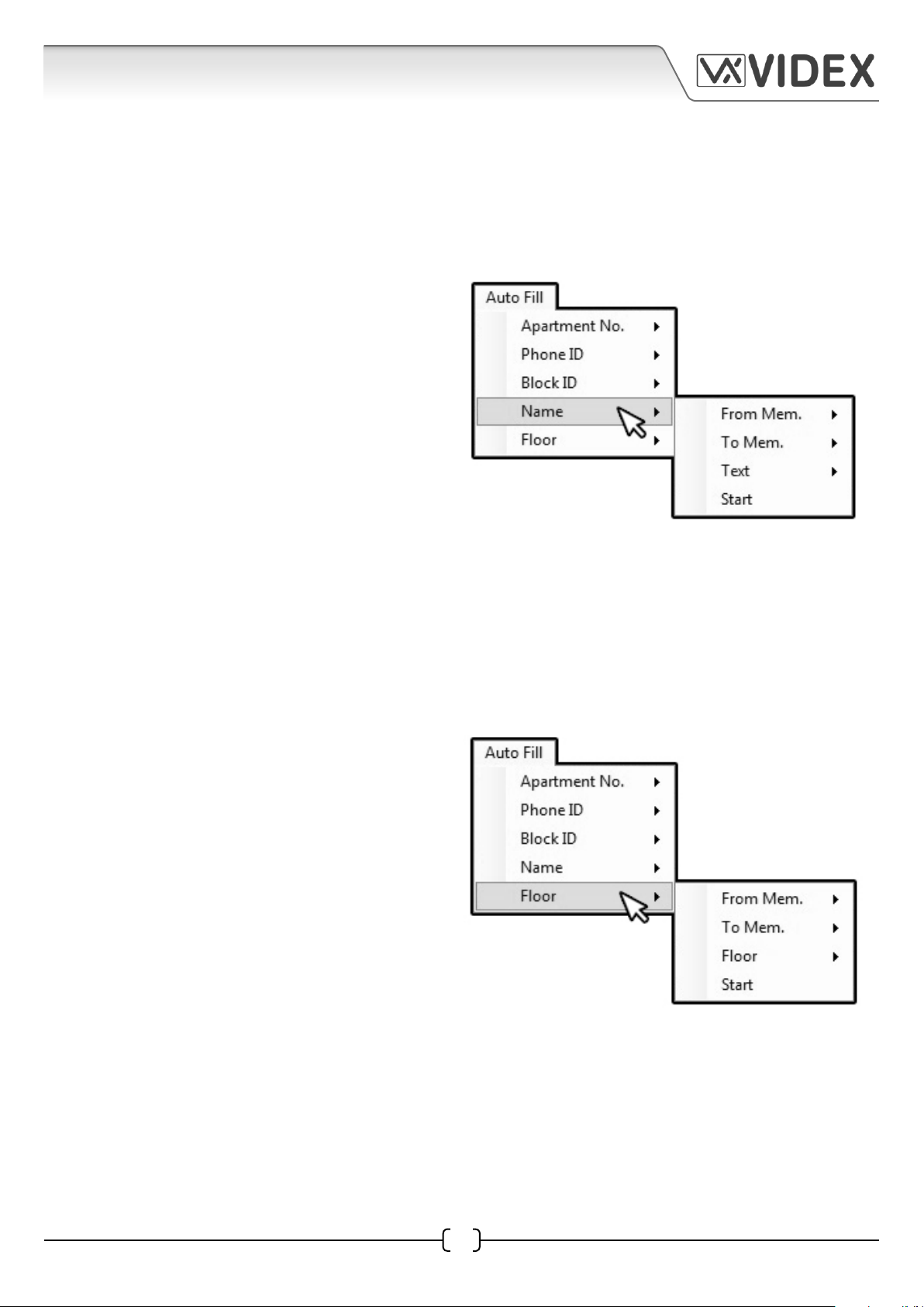
• Name - select this option from the drop down
menu, as shown to the right, to set the auto
fill parameters (From Mem; To Mem; Text and
Start) to input the name programming in the
name column. It should be noted that this
auto fill feature is only really useful if each
flat or apartment has the same designation
(e.g. flat 1, flat 2, flat 3 etc.). If the ‘#’ symbol is
input before or after any text within the text field the auto fill feature
will include the flat number when in completes the data in the Name
column (it will take the information provided in the Apt No. column, e.g.
Apt No. 125A with ‘Flat #’ input in the text field will display as Flat 125A). If individual users names
are required then they will need to be input manually in each name field down the name column.
• From Mem - is the first memory location where the name information will be stored.
• To Mem - is the last memory location where the name information will be stored.
• Text - is the ‘common’ text that will be input into the name column.
• Start - when the parameters above have been set select this option to start the auto fill
feature.
• Floor - select this option from the drop down
menu, as shown to the right, to set the auto
fill parameters (From Mem; To Mem; Floor and
Start) to input the floor number programming
in the floor column (1 - 250 max.).
• From Mem - is the first memory location where the floor
number information will be stored.
• To Mem - is the last memory location where the floor number
information will be stored.
• Floor - is the floor number of where the flat or apartment is located.
• Start - when the parameters above have been set select this option to start the auto fill
feature.
4212 PC Software Programming Guide EN-UK - V.1.0 - 17/09/15
35
Page 36
4212 PC SOFTWARE PROGRAMMING GUIDE
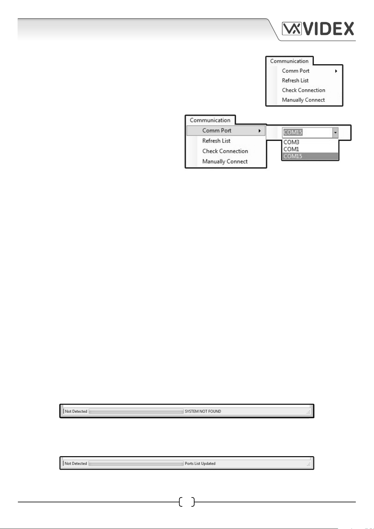
COMMUNICATION
Next from the top menu on the main programmer screen is the
Communication drop down menu, as shown on the right, from which
the following options are available; Comm Port, Refresh List, Check
Connection and Manually Connect.
• Comm Por t - selecting this option from the
drop down menu will allow an available
COM port that the 4212 digital panel is
connected to on the PC to be selected.
• Refresh List - selecting this option from the drop down menu will refresh the COM port drop
down list (please note that the COM port that the 4212 panel is connected to should be included in
the COM port drop down list).
• Check Connection - selecting this option from the drop down menu will check and refresh the
COM port connection between the PC programmer software and the 4212 digital panel.
• Manually Connect - although shown in the drop down list this option is not applicable.
BAUD
The baud rate 19200 will already be selected and all other options greyed out (when the PC programmer
software first loads up it will automatically check through the COM ports, searching under different baud
rates to see if the 4212 digital panel is connected).
ABOUT
This option confirms the current version of programming software being used.
PROGRAMMER SCREEN STATUS AND PROGRESS BAR
The bottom of the main programmer screen indicates the current status of the PC programmer
software and its connection to the 4212 digital panel. The following notes describe the different
statuses the PC programmer software will show.
• Not Detected - this status is shown when the programmer software hasn’t detected a device
(4212 digital panel) attached to the PC, as shown below.
The Refresh List option can be selected from the Communication drop down list (from the top
menu) and the status bar will confirm that the ports list has been updated, this can be seen to the
right of the progress bar as shown below.
36
EN-UK - V.1.0 - 17/09/154212 PC Software Programming Guide
Page 37
4212 PC SOFTWARE PROGRAMMING GUIDE
If the Check Connection option is then selected from the Communication drop down list the
programmer software will then search for the COM port that the 4212 panel is connected to and
re-establish a link. This can be seen to the right to the progress bar as shown below.
Once the COM port has been found by the programmer software the status bar will update. This
can be seen to the left of the progress bar. Confirmation of which COM port the 4212 panel is
connected to can be seen to the right of the progress bar as shown below.
• Detected - this status is shown when the programmer software has found a device (4212 digital
panel) attached to the PC, as shown below.
• Opened File - this status is shown when the programmer software has successfully opened a
saved file using the Open or Open Recent option from the File drop down list. The status will
update to the right of the progress bar as shown below.
• Saved File - this status is shown when the programmer software has successfully saved an open
file using the Save or Save As option from the File drop down list. The status will update to the
right of the progress bar as shown below.
• Downloading Settings - this status is shown when the programmer software downloads any
of the existing programming information (apartments, settings, logo, coded access and proximity
access) currently saved on the 4212 panel. This is done by selecting one of the Download options
from the Download drop down list from the top menu (refer to pages 31 - 32). The status and
download progress can be seen to the right of the progress bar as shown below.
• Uploading Settings - this status is shown when the programmer software uploads any of the
current setting, apartments, logo, coded access and/or proximity access from an open file into
the 4212 panel. This is done by selecting one of the Upload options from the Upload drop down
list from the top menu (refer to pages 32 - 33). The status and upload progress can be seen to the
right of the progress bar as shown below.
37
EN-UK - V.1.0 - 17/09/154212 PC Software Programming Guide
Page 38
4212 PC SOFTWARE PROGRAMMING GUIDE
• No Response - this status is shown when the programmer software has tried to make 3 attempts
to upload or download any information from the 4212 panel. The status and progress bar at
the bottom of the programmer screen will change and the ‘no response’ window will appear, as
shown below.
POWERING UP THE 4212 DIGITAL PANEL
After all connections have been made to the 4212
digital panel power up the system. When the display
initializes it will show the part number of the unit in
the middle of the display, as shown in Fig.13A. After a
few seconds it will then display the firmware version
of the unit in the middle of the display, as shown in
Fig.13B then after a few more seconds the default
panel display will be shown as shown in Fig.13C. The
4212 digital panel will be ready to connect to the PC.
Fig.13A
VX4212
00:00 01/01/01
FW VERSION
2.0.5
Fig.13B Fig.13C
Enter at No.
to search
4212 PC Software Programming Guide EN-UK - V.1.0 - 17/09/15
38
Page 39
4212 PC SOFTWARE PROGRAMMING GUIDE
CONNECTION DIAGRAM
PC or Laptop
4212 PC Software Programming Guide EN-UK - V.1.0 - 17/09/15
39
Page 40

4212 PC SOFTWARE PROGRAMMING GUIDE
QUICK SOFTWARE SETUP GUIDE
1. Insert the 2X00PC software CD into the PCs CD/DVD rom drive.
2. Select ‘RUN’ from the start menu.
3. Type in ‘D:\setup’ then press the ‘OK’ button.
4. Follow the on screen instructions to complete the setup.
5. Connect the USB cable between the PC and the 4212 digital panel.
6. Once the PC programmer software setup is complete ‘double click’ on the 2X00PC desktop icon to
launch the software.
PROXE SETUP GUIDE
1. Before launching the 2X00PC software plug the USB cable of the PROXE deskmount reader into a
spare USB port on the PC.
2. The drivers will automatically be installed by the PROXE reader.
3. The PROXE will emit a single short beep followed by a double beep and the red LED will switch ON.
4. ‘Double click’ on the 2X00PC desktop icon to launch the software.
NOTES
40
EN-UK - V.1.0 - 17/09/154212 PC Software Programming Guide
Page 41

4212 PC SOFTWARE PROGRAMMING GUIDE
4212 PC Software Programming Guide EN-UK - V.1.0 - 17/09/15
41
Page 42

4212 PC SOFTWARE PROGRAMMING GUIDE
42
EN-UK - V.1.0 - 17/09/154212 PC Software Programming Guide
Page 43
4212 PC SOFTWARE PROGRAMMING GUIDE
SOFTWARE UPDATES
Date Soware Version Revision
25/07/2015 7.0.0.13 Update of PC soware to include VX2200 Graphical Display (4212)
programming
12/10/2015 7.0.0.14 Update PC soware to include addional Logo eding features
19/10/2015 7.0.0.15 Update PC soware to include ‘oor’ auto ll feature
FIRMWARE UPDATES
Date Soware Version Revision
25/07/2015 2.0.5 Update of Coded Access and Proximity protocols
16/10/2015 2.0.6 Update of Code+Fob reading, Trade buon feature
4212 PC Software Programming Guide EN-UK - V.1.0 - 17/09/15
43
Page 44

Southern Oce
Videx Security Ltd.
1 Osprey, Trinity Park
Trinity Way’ London
E4 8TD
Northern Oce
Videx Security Ltd.
Unit 4-7 Chillingham Industrial Estate
Newcastle Upon Tyne
NE6 2XX
4212 PC Software Programming Guide EN-UK - V.1.0 - 17/09/15
 Loading...