

Page 1
66250203-EN - V0.3 - 10/07/15
1
4000 Series Vandal Resistant Range
Art.4212V-4212RV - Installation instructions
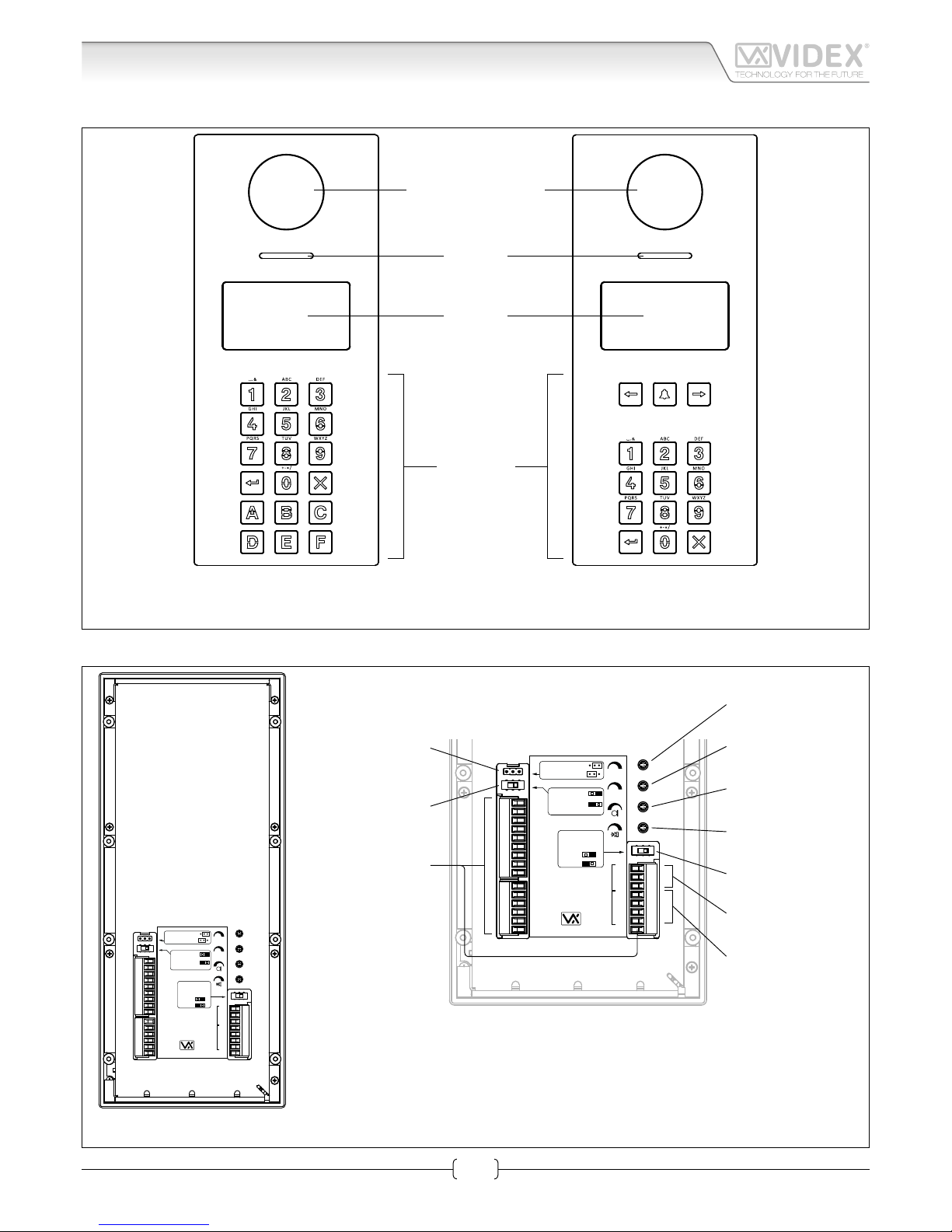
Art.4212V-4212RV Audio/video digital front panel
Wide angle colour
camera
Speaker
Display
Keyboard
Art. 4212V
Art. 4212RV
Fig. 1 Front view
12T
GNDV
V2/V
V1
PTE
TRD
NO
C
NC
SL
BS
L
−
+12
GND
OC OUTPUT
D0
D1
LR
LG
WIEGAND
A
B
GND
RS485
Dry contact output
Capacitor discharge
RS485
BUS TERMINATION
Open
Close
Balanced V1, V2
Coax V2=V, V1
not used
Balance
V.PB.CHIP
Made in Italy
12T
GNDV
V2/V
V1
PTE
TRD
NO
C
NC
SL
BS
L
−
+12
GND
OC OUTPUT
D0
D1
LR
LG
WIEGAND
A
B
GND
RS485
Dry contact output
Capacitor discharge
RS485
BUS TERMINATION
Open
Close
Balanced V1, V2
Coax V2=V, V1
not used
Balance
V.PB.CHIP
Made in Italy
Voice annunciation
speech adjustment
Speaker
volume adjustment
RS485
bus termination switch
RS485
bus connection terminals
Wiegand
connection terminals
Connection
terminals
Video signal setup
switch
Door Open Relay
Operating Mode jumper
Audio balance
adjustment
Microphone
volume adjustment
Fig. 2 Back view
Page 2

66250203-EN - V0.3 - 10/07/15
2
4000 Series Vandal Resistant Range
Art.4212V-4212RV - Installation instructions
Art.4212V-4212RV Audio/video digital front panel
DESCRIPTION
ART.4212V, ART.4212V/F, ART.4212V/SA
4000 Series Vandal resistant (front plate in brushed stainless with 2mm thickness) digital call panel for Videx VX 2200 digital systems
(2 wire BUS audio, 6 wire BUS video). This panel is compatible with the 4000 Series modular system and has the size of two 4000
Series modules.
Complementing all digital door panels manufactured by Videx is the ability for all users to have their own unique access code (each
apartment can have more than one access code). The access code can have up to six digits and is blind to onlookers. Also,integrated
into the panel is a proximity reader enabling a number of proximity fobs to be stored and used individually or in combination with
the access code to enter the building. In addition to the speaker unit functions, the panel includes a 128 x 64 pixel graphical LCD
display with blue back light (to provide text and graphical messages in multiple languages guiding a visitor through the panel operation) plus a keypad with 18 blue back lit buttons 6 of which are alpha buttons (A..F), 10 are numeric buttons (0..9) plus “ENTER”
and “CLEAR” buttons. The tenants can be called by dialling the relevant apartment code.
To complement the visual messages provided from the display, the panel has the voice annunciation facility (optional chip installation) to supply audio messages concerning the system operation. The built-in camera is a colour CCD wide angle day/night camera
with IR illumination LED’s (the day/night camera provides the best quality of view in any light condition and the wide angle camera
provides a viewing angle of 170 degrees). The camera can be set to work with composite video signal (coax cable) or balanced video
signal (one twisted pair). Interfaces include a Wiegand output (for systems based on this interface) plus two serial interfaces (USB
and RS-485) both allow for programming and event logging. The programming menu and the setup menu are protected by two
passwords with dierent login levels (the engineer password that grants full access and the system administrator password that is
limited to some specic settings) while if you operate from a PC an “Engineer’s Password” is requested to program the unit. A “Trade
Code” function is available (for periodic visitors) enabled by the specic input or by programmable time band and “Direct Call Mode”
for small installations (up to 10 apartments).
The memory capacity allows to store up to 998 users data, up to 2800 access codes, up to 2800 proximity keys and up to 4000
events. The front panel nish is brushed stainless steel while the frame nishes are the standard oered in the 4000 Series.
ART.4212RV, ART.4212RV/F, ART.4212RV/SA
As Art.4212V but using a keypad with 15 blue back lit buttons 3 of which are navigation buttons used for the repertory name facility, 10 are
numeric buttons (0..9) plus “ENTER” and “CLEAR” buttons. The tenants can be called by dialling the relevant apartment number or by searching the
relevant name using the repertory name function.
VERSIONS AVAILABLE
Art.4212V
For 4000Series modular system, ush or
surface mounting.
Art.4212RV
For 4000Series modular system, ush or
surface mounting,
with repertory name.
Art.4212V/F
Flush version.
Art.4212RV/F
Flush version with
repertory name.
Art.4212V/SA
Surface version.
Art.4212RV/SA
Surface version with
repertory name.
Page 3
66250203-EN - V0.3 - 10/07/15
3
4000 Series Vandal Resistant Range
Art.4212V-4212RV - Installation instructions
Art.4212V - 4212RV Audio/video digital front panel Operation
OPERATION
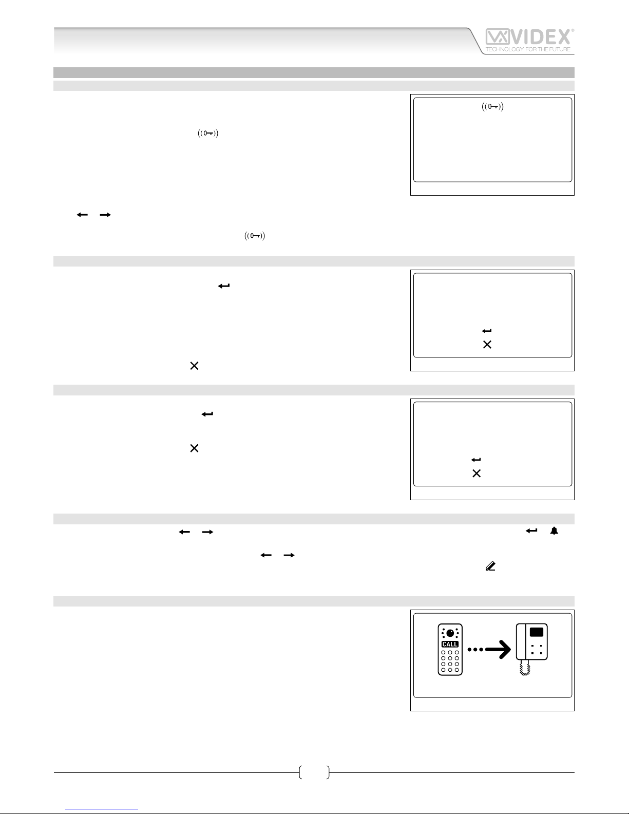
STANDBY MODE
The display alternates between HOME1 page and logo (if enabled - see “Home 2” on
pag. 9).
HOME1 (shown in Fig. 3)is composed by 4 lines:
• rst line contains date, time and
symbol (if enabled - see “RFID” on pag. 15).
Date and time have the format specied by date format and clock format (see pag. 10);
• second, third and fourth lines are edited from Home parameters menu (see “Line 1,
2, 3” on pag. 9) ;
The switching time between HOME1 and logo is specied by Switch parameter on
Home parameters menu (see pag. 9).
Press the “0” button the enter the coded access mode.
Press or (only for 15 button panels) to scroll through the users. (see “Scrolling users” on pag. 3).
Use the numeric keypad followed by enter to call an apartment (see “Flat” on pag. 7).
Passing a valid and enabled card/fob in front of
symbol will open the door.
HOW TO INSERT A CODE
From stand-by mode, pressing “0” will enter the code mode (see Fig. 4).
Every inserted digit is displayed as a dot.
will conrm the code.
The following codes can be entered:
• Master code to enter Programming menu (see “Master” on pag. 12);
• Admin code to enter Programming menu with restricted permission (see “Admin”
on pag. 12);
• Trade code to open door (if enabled - see “Trade” on pag. 12);
• a valid Access code , the door will be open, or “NOT FOUND!” message will appear.
To delete digits or exit page press
.
HOW TO CALL AN APARTMENT
From stand-by mode, enter a at number (see Fig. 5).
Each digit will be displayed. Pushing
will conrm the at number.
If at number is present in memory and user is enabled then a call request is made, or
“NOT FOUND!” message will appear.
To delete digits or exit page press .
SCROLLING USERS
From stand-by mode, pressing
or will begin scrolling. The highlighted central line is the selected user: pressing or will
make a call request.
For 15 button panel version scrolling is made using or , for 18 button version “A” and “C” buttons are used.
Callers can press a lettered key to jump to users beginning with that letter. The letter will appear next to the
abc
symbol.
If no users are found with that letter the panel will revert to the previous selection.
HOW TO MAKE A CALL
A call request can be made by either scrolling the user name or entering the at number. When a call is in progress the panel will show “Calling” as in Fig. 6.
The “CALLING” message alternates with at number (if user has made a call by typing
number) or name (if the scroll was used).
If bus is busy or intercom is not present, “BUSY!” message will appear on the screen. If
no answer after 40 seconds the call will be cleared.
If the call is answered a conversation can begin.
10:30 29/12/2015
VIDEX ELECTR.
FLAT 3
WELCOME
Fig. 3
to conrm
to canc
Code: • • • • • •
Fig. 4
123
to conrm
to canc
Fig. 5
calling
Fig. 6
Page 4
66250203-EN - V0.3 - 10/07/15
4
4000 Series Vandal Resistant Range
Art.4212V-4212RV - Installation instructions
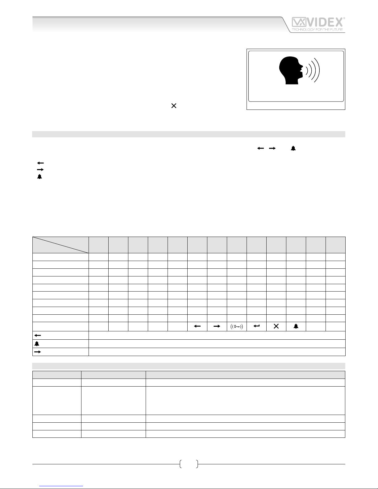
The display will be as per Fig. 7. The conversation timeout is programmable parameter
speech time (see “Speech time” on pag. 11) in seconds. If the door is released this
time is reduced to 10 seconds.
When the door is released, the animation appears on the screen and to the right of that
the following information is displayed:
• Flat number;
• block Id (if system works in MAIN MODE - see “Panel mode” on pag. 13);
• oor (if in NORMAL MODE - see “Mode” on pag. 14);
To delete a call request or close a converastion press . The panel will show the
“CALL END” message.
HOW TO TYPE TEXT
Text typing with Art.4212 is similar to mobile phone text typing. This table shows the characters and symbols that can be typed by
pressing one or more times the keypad numeric push buttons. The alphabetic push buttons “
”, “ ” and “ ” are used for special
functions:
- “ ” to scroll back;
- “ ” to scroll forward;
- “ ” to alternate between capital and lower case letters.
For instance, to type the name “VIDEX” it is necessary to press:
3 times “8” button = “V”;
3 times “4” button = “I”;
1 times “3” button = “D”;
2 times “3” button = “E”;
2 times “9” button = “X”;
Keeping pressed a button will automatically advance the cursor.
Press no. of
times
Key
1 2 3 4 5 6 7 8 9 10 11 12 13
1 space . & ! : = # @ " 1
2 a b c 2
3 d e f 3
4 g h i 4
5 j k l 5
6 m n o 6
7 p q r s 7
8 t u v 8
9 w x y z 9
0 + - * , 0
• _
Scroll back
Alternate between capital and lower case
Scroll forward
ACOUSTIC SIGNALS
Name Signal Event
Key Tone Single beep Key press.
Overow Tone/
Error Tone
Quadruple quick beep • When user inserts a numeric value that exceed the maximum value;
• When searching a user by letter and no users are found (last inserted character
is deleted);
• When saving data to memory fails.
Tag Tone Double beep When a fob or a card is passed in front of RFID antenna.
Save Tone Long single beep When saving data in memory is successful.
Open Door Tone Triple beep When door is opened.
1 CONCIERGE
Fig. 7
Art.4212V - 4212RV Audio/video digital front panel Operation
Page 5
66250203-EN - V0.3 - 10/07/15
5
4000 Series Vandal Resistant Range
Art.4212V-4212RV - Installation instructions
PROGRAMMING
TO ENTER PROGRAMMING MODE
From standby mode:
• press “0” to enter the coded access mode;
• enter the Master code (with engineer permissions - see “Master” on pag. 12) or Admin code (with limited permissions - see
“Admin” on pag. 12);
• press
to enter the code or to delete characters or exit access code mode;
• if entered code isn’t stored in memory, panel will show “NOT FOUND!”.
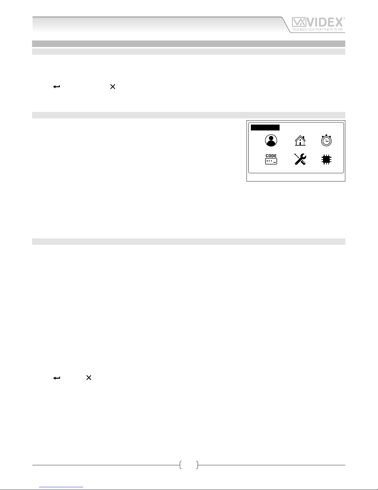
ADDING USERS
From Programming menu (Fig. 8):
• press “1” to enter the user menu;
• then press “2” to add a new user;
• The adding a new user routine is dierent depending on on if the panel mode is
COMPATIBILITY MODE or NORMAL MODE:
» In COMPATIBILITY MODE, user can add elds in following order:
NAME -> FLAT -> CODE -> FLOOR -> ENABLE -> PHONE -> BLOCK (only in MAIN
MODE);
» In NORMAL MODE:
NAME -> FLAT -> FLOOR -> ENABLE -> PHONE -> BLOCK (only in MAIN MODE);
• At the end of the routine the system checks if the user can be saved to memory.
New item is invalid when Phone ID and Block ID are equal to another one in memory and the at number doesn’t match. In this
case a “ALREADY IN MEMORY” message will appear.
To modify users please refer “User parameters” on pag. 7.
CODE MANAGEMENT
This routine is only valid in NORMAL MODE. When in COMPATIBILITY MODE, please refer to “User parameters” - “Code” on pag. 7.
From Programming menu:
• press “1” to enter the user menu then “1” to modify a user.;
• nd the user by name or at;
• press “3” and enter in User Code menu;
HOW TO ADD A CODE
• press “3” to add a code;
• insert code;
• if code is not already in memory, display will show “ITEM SAVED”, or “ALREADY IN MEMORY” with corresponding acoustic signals.
Note: if in Code + fob mode. Adding a code will automatically be followed by inserting a fob.
HOW TO MODIFY A CODE
• press “1” to modify a code;
• insert code. If searched code is present, panel enters user Code modify page;
• press “1” to enable or disable code;
• press “2” to edit the code;
• type access code;
• press
to save or to delete characters or exit edit mode without saving. If code is not already in memory, display will show
“ITEM SAVED”, else “ALREADY IN MEMORY” with corresponding acoustic signals.
HOW TO DELETE A CODE
• press “2” to enter in User Code Delete menu;
• press “1” to delete single item or “2” to delete all codes linked with selected users;
» if user has previously selected the “All” option, panel will delete all codes linked with selected user and “DELETED MESSAGE” will appear;
» if user has previously selected “Single” the panel will enter the User Code Search:
› if searched code is present, panel will show” ITEM SAVED” message;
› if searched code isn’t present in memory, panel will show “NOT FOUND!”.
1: 2: 3:
4: 5:
6:
Prog. Menu fw version X.X.X
Fig. 8
Art.4212V - 4212RV Audio/video digital front panel Programming
Page 6
66250203-EN - V0.3 - 10/07/15
6
4000 Series Vandal Resistant Range
Art.4212V-4212RV - Installation instructions
KEY MANAGING
From Programming menu:
• from the main menu press “1” to enter the user menu;
• select user searching by name or at;
• Press “8” to enter user tag menu;
HOW TO ADD A KEY
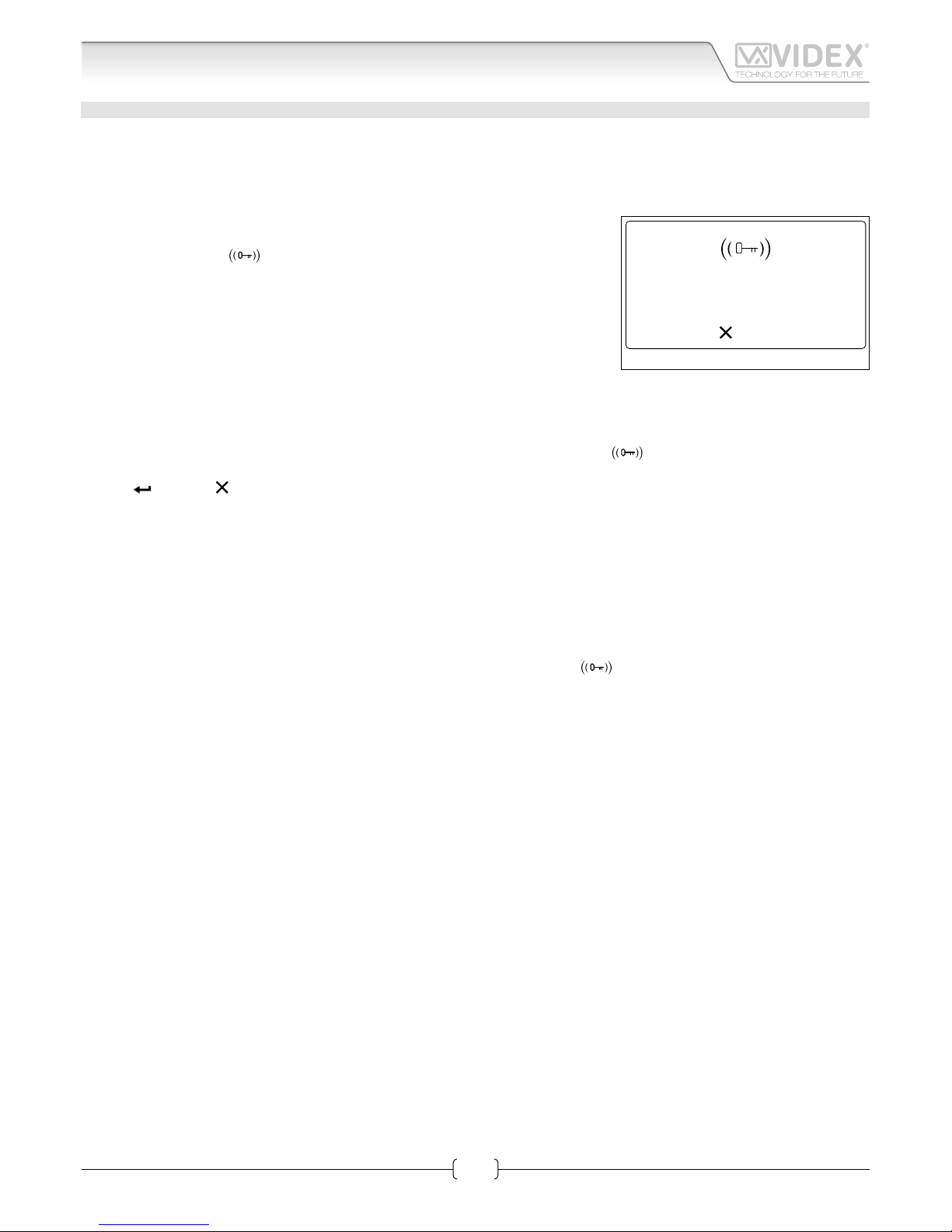
• press “3” to add a key: the dislpay will show “INSERT KEY” as shown in Fig. 9
• pass the key over the
symbol;
• if key is not already in memory display will show “ITEM SAVED”, or “ALREADY IN
MEMORY” with corresponding acoustic signals.
NOTE: when security mode is Code + Fob it is not possible to add a fob in this way. It
must be added with a code in the code menu..
HOW TO MODIFY A KEY
• press “1” to enter the User Tag Search menu;
• press “1” to search by number or “2” to search by key;
» if user has previously select search by number option, he has to enter the key number;
» if user has previously select search by key option, he has to pass card/fob over the
symbol;
• if searched key is present, the user tag modify page will appear: pressing “1” to enable/disable the key;
• press to save or to exit without saving.
If searched key isn’t present in memory, panel will show “NOT FOUND!”.
HOW TO DELETE A KEY
• press “2” to enter the User Tag Delete menu;
• press “1” to delete single key or “2” to delete all keys linked with selected users;
» if user has previously select “Al l”, all keys associated with that user will be deleted, “DELETED MESSAGE” will appear;
» if user has previously select “Single” a search will be needed to locate the key:
› press “1” to search by number or “2” to search by key;
– if user has previously selected search by number, the key number must be entered;
– if user has previously selected search by key, pass the card/fob over the
symbol.
› if searched key is present, panel will show ” ITEM SAVED” message;
› if searched key isn’t present in memory, panel will show “NOT FOUND!”.
to exit
Insert key
Fig. 9
Art.4212V - 4212RV Audio/video digital front panel Programming
Page 7

66250203-EN - V0.3 - 10/07/15
7
4000 Series Vandal Resistant Range
Art.4212V-4212RV - Installation instructions
PROGRAMMING PARAMETERS
USER PARAMETERS
User par. menu Parameter Name Programming Method Permission Default value
1: Usr User name By panel and PC software All “ “
2: Flat Flat By panel and PC software All /
3: Code Code By panel and PC software All /
4: Fl. Floor By panel and PC software All /
5: En. Enable By panel and PC software All Enabled
6: Ph. Id Phone Id By panel and PC software Only Engineer /
7: Bl. Id Block Id By panel and PC software Only Engineer /
8:Tag Tag By panel and PC software All /
USER NAME
The user name can be up to 16 characters long and is displayed during searching and calling.
Modify routine
• select user searching by name or at;
• press “1” button to enter into edit mode;
• type name;
• press
to save or to delete characters or exit edit mode without save.
FLAT
The at number is entered by the visitor to call a at. It can be 1 to 6 digits long.
Modify routine
• select user searching by name or at;
• press “2” button to enter into edit mode;
• type at number;
• press
to save or to delete characters or exit edit mode without save.
CODE
Access Code is entered by the user to open the door.
Modify routine depends on Mode setting: in COMPATIBILITY MODE only one code is possible per user. Pressing “3” will allow the
code to be edited.
In NORMAL MODE multiple codes can be assigned to a user. This routine is described in “Code management” on pag. 5
In both cases codes can be from 3 to 6 digits using keys 0 - 9. It can be disabled by leaving it blank.
Modify routine (only for COMPATIBILITY MODE)
• select user searching by name or at;
• press “3” to enter into edit mode;
• type new access code;
• press
to save or to delete characters or exit edit mode without saving.
Art.4212V - 4212RV Audio/video digital front panel Programming
Page 8

66250203-EN - V0.3 - 10/07/15
8
4000 Series Vandal Resistant Range
Art.4212V-4212RV - Installation instructions
FLOOR
The oor eld displays the oor number of the user called. It is available only in NORMAL MODE and can be any value from “1” to “250”.
Modify routine
• select user searching by name or at
• press “4” to enter into edit mode;
• type oor number;
• press
to save or to delete characters or exit edit mode without save.
ENABLE
It species whether User is enabled or not. If a visitor tries to call a disabled user typing the at number, display will show “NOT
FOUND” otherwise the intercom for that at will be called. Intercom specied by Phone Id and Block Id.
Modify routine
• select user searching by name or at;
• press “5” to enter into edit mode;
• press “5” to enable or disable;
• press
to save or to exit edit mode without save.
PHONE ID
The phone ID represents the address of the intercom to call (Set by the 8 way dip switches in the intercom).
Modify routine
• select user searching by name or at;
• press “6” to enter into edit mode;
• type Phone Id number;
• press
to save or to delete characters or exit edit mode without save.
BLOCK ID
Block Id eld species the address of Art.2206N. It can assume values from “1” to “15”. This eld is visible only if the panel is set to
MAIN MODE (see “Panel mode” on pag. 13).
Modify routine
• select user searching by name or at;
• press “7” to enter into edit mode;
• type Block Id number;
• press
to save or to delete characters or exit edit mode without save.
TAG
The tags (key or fob) allow users to open the door. Three fob code lengths are supported (2, 3 & 4 bytes). It is specied by Tag width
parameter (see “Fob width” on pag. 15).
User can be linked to more than one access code. The modify routine is described in “Key managing” on pag. 6
Art.4212V - 4212RV Audio/video digital front panel Programming
Page 9

66250203-EN - V0.3 - 10/07/15
9
4000 Series Vandal Resistant Range
Art.4212V-4212RV - Installation instructions
HOME PARAMETERS
Home par. menu Parameter Name Programming method Permission Default value
1: Line 1 Line 1 By panel and PC software All /
2: Line 2 Line 2 By panel and PC software All /
3: Line 3 Line 3 By panel and PC software All /
4: Home 2 Home 2 By panel and PC software All Disabled
5: Switch Time Switch time By panel and PC software All 2 s
LINE 1, 2, 3
Each line can be up to 16 characters long and will appear on the main screen in standby. Enter the string and press
. The have a
blank line enter one or more space characters.
Modify routine
• press “1”, “2” or “3” to enter into edit mode;
• enter the string;
• press to save or to delete characters or exit edit mode without saving.
HOME 2
To enable a second screen which can display a logo.
Modify routine
• press “4” button to enter into edit mode;
• press “4” to enable or disable;
• press
to save or to exit edit mode without saving.
SWITCH TIME
Time delay when switching between the two main screens.
Modify routine
• press “5” to enter into edit mode;
• enter time is seconds: it must be between “1“ and “250”;
• press
to save or to delete characters or exit edit mode without saving.
Art.4212V - 4212RV Audio/video digital front panel Programming
Page 10

66250203-EN - V0.3 - 10/07/15
10
4000 Series Vandal Resistant Range
Art.4212V-4212RV - Installation instructions
TIME PARAMETERS
Time par. menu Parameter Name Programming method Permission Default value
1: Clock Clock format By panel and PC software All 0-23
Clock By panel and PC software All /
BST/GMT Enable/disable By panel All Enabled
2: Date Date format By panel and PC software All European
Date By panel and PC software All /
Day By panel All /
3: Trade Trade enable By panel and PC software All Disabled
Trade start By panel and PC software All /
Trade end By panel and PC software All /
4: Relay Time Relay time By panel and PC software Only Engineer 2 s
5: Speech Time Speech time By panel and PC software Only Engineer 120 s
CLOCK FORMAT
It changes the clock format shown on the home page.
Select either 12 hour or 24 hour clock format.
Modify routine
• press “1” to enter the clock menu;
• press “1” to enter into edit mode;
• press “1” to switch from 1-12 to 0-23 and viceversa;
• press
to save or to exit edit mode without saving.
CLOCK
Set the time on the door panel.
Modify routine
• press “1” to enter the clock menu;
• press “2” to enter edit mode;
• enter the hour, minutes and seconds (all elds are composed of two digits). After entering two digits to set the hour it automatically advances to the minutes and then to seconds.If in 12 hour clock format, after seconds it is possible to select AM/PM;
• After setting the last parameter the time will be saved.
BST/GMT ENABLE/DISABLE
Enable or disable BST/GMT automatic Summer/Winter time adjustment.
Modify routine
• press “3” to enter edit mode;
• in edit mode, press “3” to enable or disable the facility;
• press
to save or to exit edit mode without saving.
DATE FORMAT
It changes the date format shown on the home page.
The date can either be in EU (dd/mm/yy) or US (mm/dd/yy) format.
Modify routine
1. press “2” to enter the date menu;
2. press again “1” to enter into edit mode;
3. press “1” to switch from EU to US and viceversa;
4. press
to save or to exit edit mode without saving.
Art.4212V - 4212RV Audio/video digital front panel Programming
Page 11

66250203-EN - V0.3 - 10/07/15
11
4000 Series Vandal Resistant Range
Art.4212V-4212RV - Installation instructions
DAT E
Set the date in the call panel.
Modify routine
• press “2” to enter the date menu;
• press “2” to enter edit mode;
• rst eld will be day when in EU format or month when in US format. All elds are two digits. After entering the two digit number
it will automatically advance to the next eld;
• after setting the last parameter time will be saved.
DAY
Set the day of the week.
Modify routine
• press “3” to enter edit mode;
• in edit mode, press “3” repeatedly to scroll through the days;
• press
to save or to exit edit mode without saving.
TRADE ENABLE
Enables the trade facility working in conjunctions with the trade start and trade end time band and the TRD connection terminal.
When the TRD connection is shorted to 0V and the time is within the trade time band setting it is possible for a user to type in the
trade code to open the door.
Modify routine
• press “3” to enter the trade menu;
• press “1” to enter edit mode;
• press “1” to enable or disable the facility;
• press
to save or to exit edit mode without saving.
TRADE START TRADE END
The beginning and end times of the trade time band.
Modify routine
• press “3” to enter the trade menu;
• press “2” or “3” to enter edit mode;
• enter the hour, minutes and seconds (all elds are composed of two digits). After entering two digits it will automatically advance
to the next eld. FORMAT is 12 hour then then you will be able to enter AM or PM after the seconds eld.
• After setting the last parameter the time will be saved.
RELAY TIME
This parameter species how long the relay remains energised when the activated.
Modify routine
• press “4” to enter edit mode;
• edit relay time: it must be between “1“ and “255”;
• press
to save or to delete characters or exit edit mode without saving.
SPEECH TIME
This parameter species the maximum speak duration. From 1 to 255 seconds”.
Modify routine
• press “5” to enter edit mode;
• edit relay time: it must be between “1“ and “255”;
• press
to save or to delete characters or exit edit mode without saving.
Art.4212V - 4212RV Audio/video digital front panel Programming
Page 12

66250203-EN - V0.3 - 10/07/15
12
4000 Series Vandal Resistant Range
Art.4212V-4212RV - Installation instructions
CODE PARAMETERS
Code par. menu Parameter Name Programming method Permission Default value
1: Master Master By panel and PC software Only Engineer 111111
2: Trade Trade By panel and PC software Only Engineer 000000
3: Admin Admin By panel and PC software Only Engineer 222222
4: Manage Trade Card / By panel and PC software Only Engineer /
MASTER
The master code must to between 3 to 6 digits and must also be dierent from the admin, trade and user codes. Entering the correct
master code will switch the panel in to programming mode with engineer permissions.
Modify routine
• press “1” to enter into edit mode;
• insert new code;
• press
;
• insert the same code to conrm;
• press to save or to delete characters or exit edit mode without saving.
TRADE
The trade code works within the trade time band and only when TRD is shorted to 0V.
It must be between 3 to 6 digits and dierent to all other codes. Entering the correct code when the above requirements are met
will open the door for the programmed time.
Modify routine
• press “2” to enter into edit mode;
• insert new code;
• press
;
• insert the same code to conrm;
• press to save or to delete characters or exit edit mode without saving.
ADMIN
The admin code will switch the door panel in the programming mode similar to the master code but with restricted permissions.
The code must to between 3 to 6 digits and dierent from all other codes.
Modify routine
• press “3” to enter into edit mode;
• insert new code;
• press
;
• insert the same code to conrm;
• press to save or to delete characters or exit edit mode without saving.
MANAGING TRADE CARD
Add, edit or delete proximity cards which can be used for trade purposes only during active timeband settings.
Add routine
• press “4” to enter into edit mode;
• press “3” to add and then present a card to the reader when asked;
• press
to exit edit mode.
Art.4212V - 4212RV Audio/video digital front panel Programming
Page 13

66250203-EN - V0.3 - 10/07/15
13
4000 Series Vandal Resistant Range
Art.4212V-4212RV - Installation instructions
SYSTEM SETTINGS
System par. menu Parameter Name Programming method Permission Default value
1: Language Language By panel and PC software Only Engineer English
2: ID ID By panel and PC software Only Engineer 1
3: Master Master By panel and PC software Only Engineer Enabled
4: Panel mode Panel mode By panel and PC software Only Engineer Local
Security Level Only by PC software / Fob or Code
Mode Only by PC software / Compatibility mode
Enable Direct Call Only by PC software / Disabled
Proximity Access Mode Only by PC software / Stand alone mode
LANGUAGE
Languages supported are: English, Italian, Spanish, Portuguese, French, German, Czech, Croatian, Danish, Polish and Slovenian.
Only user messages change language, the programming menu’s are always in English.
Modify routine
• press “1” to enter into edit mode;
• press “1” repeatedly to scroll through the available languages;
• press
to save or to exit edit mode without saving.
ID
The panel ID came be from 1 to 15. Each panel on a system should have a unique ID.
Modify routine
• press “2” to enter into edit mode;
• Enter the panel ID from 1 to 15;
• press
to save or to delete characters or exit edit mode without saving.
MASTER
Species if the panel is a master or a slave. On each bus there should only be one master, all other panels on that bus should be slaves.
Modify routine
• press “3” to enter into edit mode;
• press “3” to enable or disable;
• press
to save or to exit edit mode without saving.
PANEL MODE
Species if the system includes the 2206N bus exchange devices or not and if the panel is a main panel or a local panel. If there are no
2206N devices on the system then this setting should be LOCAL. If there are 2206N devices on the system and this panel is a main entrance calling all apartments then this setting should be MAIN. If the panel is a block entrance panel then this setting should be LOCAL.
Modify routine
• press “4” to enter into edit mode;
• press “4” to switch from LOCAL to MAIN and viceversa;
• press
to save or to exit edit mode without saving.
SECURITY LEVEL
Art.4212 can work in two dierent security modes: Fob or Code and Fob + Code.
In Fob or Code, key and code are linked only with user. Insertion of enabled code or passing a key over the reader will open the door.
In Fob + Code, key and code are linked together. Single code is linked with single key.A user must enter a code and present a key to
open the door. Parameter can be changed only through PC programming routine.
Art.4212V - 4212RV Audio/video digital front panel Programming
Page 14

66250203-EN - V0.3 - 10/07/15
14
4000 Series Vandal Resistant Range
Art.4212V-4212RV - Installation instructions
MODE
Options are COMPATIBILY MODE or NORMAL MODE. COMPATIBILITY MODE guarantees retrocompatibility with older program-
ming interfaces but restricts the features of the panel.
NORMAL MODE enables features of oor eld in user item, multiple code-to-user or key-to-user linking. This means that user can
manage more than one open door code and key.
In COMPATIBILITY MODE each user only has one access code.
ENABLE DIRECT CALL
It species whether Direct Call Mode is active or not. If yes, only the rst 18 or 15 (depending on keyboard conguration) users
written in memory are active. Pushing the rst key from top left corner of keyboard will call rst user memory location.
PROXIMITY ACCESS MODE
This parameter species if the proximity reader works in a self contained standalone mode or is connected via a Wiegand interface
to an external controller such as Portal Plus.
STANDALONE MODE: when a fob/code is used the panels internal memory is checked for a match. If a match is found the relay will
energise and the display will show the door opening. If no match is found the display will show ‘NOT FOUND’.
WIEGAND MODE: When a fob/code is used the panel sends the data to the Wiegand output and awaits a reply. If the external Wiegand controller replies by setting the LR terminal to 0V then the fob/code is denied and the display will show ‘NOT FOUND’. If the
external Wiegand controller replies by setting the LG terminal to 0V then the key is accepted and the display will show door open.
If the Wiegand control does not reply then the panel will show ‘NOT FOUND’.
Art.4212V - 4212RV Audio/video digital front panel Programming
Page 15

66250203-EN - V0.3 - 10/07/15
15
4000 Series Vandal Resistant Range
Art.4212V-4212RV - Installation instructions
DEVICE
Device par. menu Parameter Name Programming method Permission Default value
1: RFID RFID By panel and PC software Only Engineer Disabled
2: Voice Chip Voice Chip By panel and PC software Only Engineer Disabled
3: Wiegand Wiegand By panel and PC software Only Engineer 26 bit
Fob width Only by PC software Only Engineer 2 byte
RFID
Enables or disables the proximity access reader within the door panel.
Modify routine
• press “1” to enter into edit mode;
• press “1” to enable or disable;
• press
to save or to exit edit mode without saving.
VOICE CHIP
Voice annunciation facility. It can be either DISABLED, SINGLE or COMBINED.
In SINGLE mode number called is pronounced singularly (i.e. 123 ... one, two three).
In COMBINED mode number called is pronounced all in one (i.e. 123 ... one hundred and twenty three).
Modify routine
• press “2” to enter into edit mode;
• press “2” to switch between DISABLED, SINGLE or COMBINED;
• press
to save or to exit edit mode without saving.
WIEGAND
This parameter species Wiegand protocol format. Wiegand 26 bit and 34 bit are supported.
Modify routine
• press “3” to enter into edit mode;
• press “3” to switch from 34 bit or 26 bit and viceversa;
• press
to save or to exit edit mode without saving.
FOB WIDTH
This option species how much of the fobs internal code is used. It can be set to 2, 3 or four bytes.
This parameters can only e set using the PC software. When set to 2 bytes it will send the 2 least signicant bytes of the fob, when
set to 3 will be the 3 least signicant bytes and 4 will be the four least signicant bytes.
Art.4212V - 4212RV Audio/video digital front panel Programming
Page 16

66250203-EN - V0.3 - 10/07/15
16
4000 Series Vandal Resistant Range
Art.4212V-4212RV - Installation instructions
RESET AND TEST
RESTORE TO FACTORY PRESET
• Power o then power on the panel;
• when the display shows “VX4212”, keep the enter button pressed;
• the display will show “RESET TO FACTORY SETTING”.
TESTING CONNECTION
• insert Master code;
• press “5” and enter in System menu;
• press “5” and init the test. Now display will look like Fig. 10.
• the cental line describes the current test status; Flat, Ph. Id and Bl. Id specify which intercom is under test. Panel makes a call to every item stored in memory: if it receives
the acknoledge from intercom status will be OK and after 2 seconds skips to test the
next intercom. If no ack is received then status reports Fail: it is kept for 10 seconds.
After that time routine continues on testing next intercom. User can stop routine by
pressing
: test is paused. A further press of will end the routine. To resume test
press .
JUMPERS, SWITCHES AND CONNECTION TERMINALS
JUMPERS
Dry contact output
Capacitor discharge
SWITCHES
Balanced V1, V2
Coax V2=V, V1 not used
RS485 BUS TERMINATION
Open
Close
CONNECTION TERMINALS
12T +12Vdc Camera power supply unit
GNDV Camera power supply ground & video ground
on coax video system
V2/V Balanced video signal sync- (V2) or coax video
signal (V). Refer to “SWITHCES” table on this page
V1 Balanced video signal Sync+
PTE Push to exit button
TRD Trade signal (from Art.701T or other devices)
NO Relay out - normally open contact
C Relay out - common contact
NC Relay out - normally close contact
SL Accessory control signal
BS “Busy system” signal
L Bus connection - positive
− Bus connection - negative
+12 Power supply - positive
OC OUTPUT Open collector output
RS485 CONNECTION TERMINALS
A
RS-485 serial interface
B
GND Ground
WIEGAND CONNECTION TERMINALS
D0 Data0
D1 Data1
LR Red denied LED status output
LG Green accept LED status output
TECHNICAL SPECIFICATION
Memory capacity: 998 users - 2800 keys - 2800 codes
Working voltage: 12 Vdc +/- 10%
Max absorb: about 350mA
Working Temperature: -10 +50 °C
stop
Testing...
Flat: 1
Ph. Id. 1
System-Test Connection
Fig. 10
Art.4212V - 4212RV Audio/video digital front panel Programming
Page 17

66250203-EN - V0.3 - 10/07/15
17
4000 Series Vandal Resistant Range
Art.4212V-4212RV - Installation instructions
Art.4212V-4212RV Audio/video digital front panel
Page 18

66250203-EN - V0.3 - 10/07/15
18
4000 Series Vandal Resistant Range
Art.4212V-4212RV - Installation instructions
Art.4212V-4212RV Audio/video digital front panel
Page 19

66250203-EN - V0.3 - 10/07/15
19
4000 Series Vandal Resistant Range
Art.4212V-4212RV - Installation instructions
Flush mounting door station installation
Fig. 1 Fig. 2 Fig. 3
Fig. 4 Fig. 5
1. Embed the ush mounting box into the wall (160-170cm between the top of the box and the oor level as shown in Fig. 1) passing the cables (Fig. 2) through a cable knockout hole in the box;
2. Make all the connections on the removable terminal blocks (Fig. 2), then plug back into the panel (Fig. 3), setup the dip-switches
as per provided connection diagram or instruction sheet, then power up the system and check that it works correctly;
In order to prevent water ingress we highly recommend using a silicon sealant between the plate and the wall (Fig. 4);
3. Fix the plate to the ush mounting box using the screwdriver provided (torx end) and the pin machine torx screws (Fig. 5).
Do not over tighten the screws more than necessary.
Page 20

66250203-EN - V0.3 - 10/07/15
20
4000 Series Vandal Resistant Range
Art.4212V-4212RV - Installation instructions
Surface mounting door station installation
A
B
C
C
Fig. 1
B
Fig. 2
B
F
D
D
E
G
G
E
Fig. 3
Fig. 4
B
C
A
C
Fig. 5
1. To separate the panel A from the surface box B, rst remove the two screws C located on the bottom of the surface box using
a screwdriver, then lever the panel from the bottom to extract it (Fig. 1);
2. Place the surface box B against the wall (165-170cm between the top of the box and the oor lever) and mark the 4 xing holes
for the wall plugs and the hole for the cables (Fig. 2);
3. Drill the 4 xing holes D, insert the wall plugs E and feed the cables F through the surface box, x surface box to the wall using
the screws G (Fig. 3);
4. Connect the wires using a terminal screw driver then setup the dip-switches as per provided connection diagram or instruction
sheet, then power up the system and check that it works correctly (Fig. 4);
5. Insert the top end of the panel A rst, then level down and x to the surface box B with the two screws C (Fig. 5).
Do not over tighten the screws more than necessary.
CUSTOMER SUPPORT
All Countries:
VIDEX ELECTRONICS S.P.A.
www.videx.it - technical@videx.it
Tel: +39 0734-631669
Fax: +39 0734-632475
UK Customers:
VIDEX SECURITY LTD
www.videx-security.com
Tech Line: 0191 224 3174
Fax: 0191 224 1559
The product is CE marked demonstrating its conformity and is for distribution within all member states of the EU with no restrictions. This product
follows the provisions of the European Directives 2004/108/ECC (EMC);
2006/95/ECC (LVD) and 93/68/ECC (CE marking).
 Loading...