

Page 1
66250190 - V2.2 - 28/02/18
- 1 -
4000 Series
Art.4203 - Installation instructions
EC
A
D
F
B
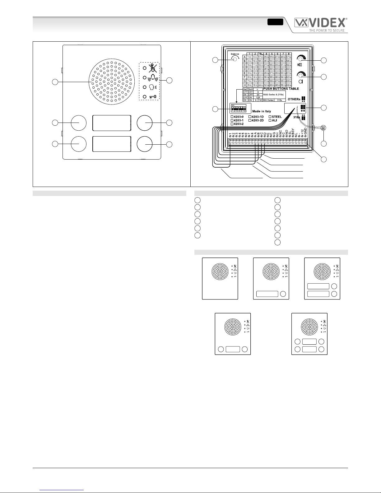
Fig. 1 Front
H
G
L
I
M
O
N
Black - Button 4
White - Button 3
Red - Button 2
Yellow - Button 1Blue - Common
Fig. 2 Back
DESCRIPTION
The Art.4203 unit is a digital front panel based on a “2 wire”
BUS intercom system that enables the connection of traditional
push buttons. This unit is housed in a single 4000 Series module and is available in Mirror Stainless Steel (standard nish) or
anodized aluminium (add /A after the product code). It incorporates the functional interface connections from functional to
digital and the speaker unit module with 0, 1, 2 or 4 call buttons.
This device enables the connection of up to 64 functional push
buttons using standard 4000 Series extension module panels
Art.4842, Art.4843, Art.4844, Art.4845 and relevant double button
version Art.4842D, Art.4843D, Art.4844D and Art.4845D. The push
buttons already tted to the module are to be subtracted from the
number of those to be inserted, i.e. 4, 2 or 1 according to the model.
The module built-in buttons, 1, 2 or 4 (Art.4203-1, Art.4203-1D or
Art. 4203-2 and Art. 4203-2D) as factory presetting are set as 1
st
ID
PHONE or 1st and 2nd or 1st, 2nd 3rd and 4th of the addresses group selected by dip-switches 2 and 3. Operating on the wires carried out
from the module, you can set the buttons how you want. If a number
of push buttons greater than 64 is required, more Art.4203 modules
can be used to have up to 150 buttons with 900 Series, up to 180 buttons with 3000 Series (except intercom Art.316x model) and up to
255 with the low cost intercom Art.316x..All the modules must be
assembled using the 4000 Series ush or surface mounting units.
The Art.4203 can work with 900 Series or 3000 Series or with
the new low cost intercom Art.3161.
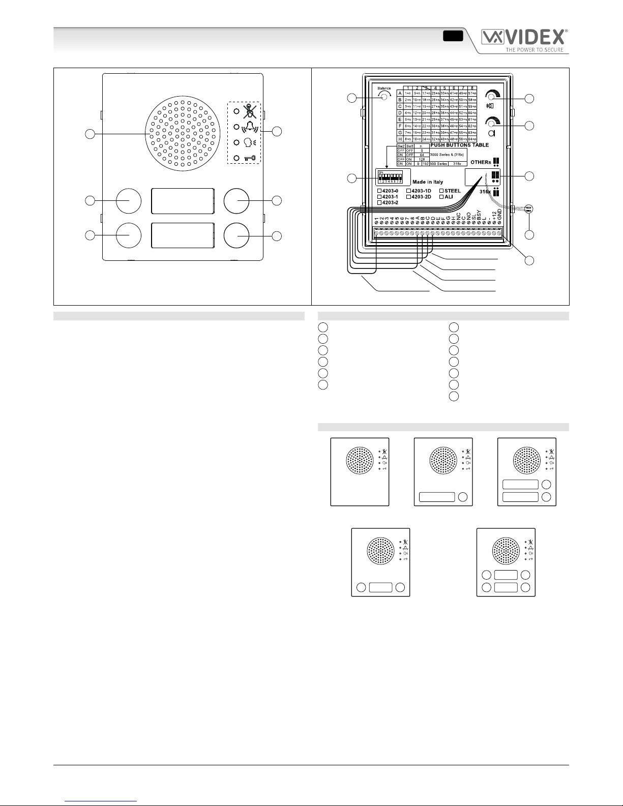
LEGEND
A
Loudspeaker
B
LEDs
C
Push button 4 - black wire
D
Push button 3 - white wire
E
Push button 2 - red wire
F
Push button 1 - yellow wire
G
Balance
H
Loudspeaker volume
I
Microphone volume
L
8 way dip-switch
M
Jumpers
N
Connection terminals
O
Microphone
AVAILABLE VERSIONS
Art.4203-0
1
Art.4203-1
1
2
Art.4203-2
13
Art.4203-1D
13
4 2
Art.4203-2D
Art.4203 Digital to functional interface module/"2 Wire bus" system
ENG
Page 2
66250190 - V2.2 - 28/02/18
- 2 -
4000 Series
Art.4203 - Installation instructions
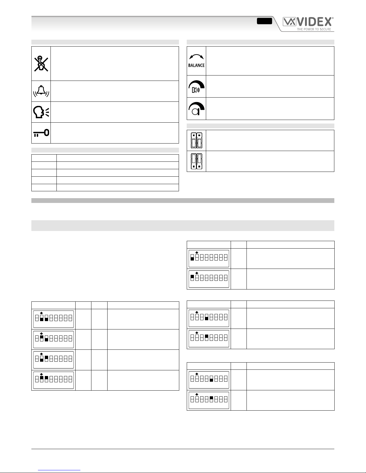
LEDS
The rst LED (red), if switched ON, indicates that it is
not possible to make a call because a call or a conversation is in progress (from the outdoor station from
which you are calling or from another outdoor station
on system with multiple entrances).
The second LED (red), if switched ON, indicates that a
call is in progress. The LED will be switched OFF when
the call is answered.
The third LED (yellow), if switched ON, indicates that it is
possible to speak. The LED will be switched OFF at the end
of conversation (or at the end of the conversation time).
The fourth LED (green), if switched ON, means that the
door lock has been operated. It will be switched OFF at
the end of the “door opening” time.
WIRESBUTTON TABLE
Blue Buttons common
Yellow Button 1
Red Button 2
White Button 3
Black Button 4
CONTROLS
Balance
Prevent Larsen eect on bidirectional audio conversation.
Refers to the Speech adjustment of “VX2200 - General directions for installation” techincal manual
Loudspeaker volume
Adjust the loudspeaker volume.
Rotate clockwise to increase or anti-clockwise to decrease
Microphone volume
Adjust the microphone volume.
Rotate clockwise to increase or anti-clockwise to decrease
JUMPERS
“Art.316X” position
For programming only with intercoms Art.3161 &
Art.3162
“Others” position
For programming with 900 & 3000 Series except
intercom Art.3161 & Art.3162
PROGRAMMING
The programming is carried out exclusively through the conguration of the two jumpers and the 8 way dip-switch both accessible
from the back of the module. Depending on the 2 jumpers settings, the 8 way Dipswitches have a dierent function.
WITH THE TWO JUMPERS IN UPPER POSITION “OTHERS” TO WORK WITH 900 & 3000 SERIES EXCEPT INTERCOM ART.3161
& ART.3162, THE 8 WAY DIPSWITCH ENABLES THE FOLLOWING:
• Program the unit as a Master or a Slave (switch 1);
• Program the 64 push buttons group (switches 2 & 3);
• Program the conversation time (switch 4);
• Program the door opening time (switch 5);
• Program the device number (switches 6,7,8);
CONFIGURATION OF THE UNIT AS A MASTER OR A SLAVE
Switch Nr. 1 Setting Up
ON
1 2 3 4 5 6 7 8
OFF = Slave
ON
1 2 3 4 5 6 7 8
ON = Master (default)
PROGRAMMING OF THE 64 PUSH BUTTONS GROUP
Switch Nr. 2 Nr.3 Setting Up
ON
1 2 3 4 5 6 7 8
OFF OFF = from 1 to 64
ON
1 2 3 4 5 6 7 8
ON OFF = from 65 to 128
ON
1 2 3 4 5 6 7 8
OFF ON = from 129 to 180
ON
1 2 3 4 5 6 7 8
ON ON
= from 1 to 64
with 900 Series devices
Switches 2 & 3 dene the range of Phone IDs generated by the unit
when the call buttons are pressed. For example with dip-switch 2
and 3 both OFF, the push button connected between the Art.2203
terminals “1” and “a” generates the ID PHONE 1 while the same
push button, with dip-switch 2 ON and dip-switch 3 OFF, will generate the PHONE ID 65. The fourth range of push button groups
can be used with the 900 Series intercoms and videointercoms.
PROGRAMMING THE CONVERSATION TIME
Switch Nr. 4 Setting Up
ON
1 2 3 4 5 6 7 8
OFF = 1 minute
ON
1 2 3 4 5 6 7 8
ON = 2 minutes
PROGRAMMING THE DOOR OPENING TIME
Switch Nr. 5 Setting Up
ON
1 2 3 4 5 6 7 8
OFF = 2 seconds
ON
1 2 3 4 5 6 7 8
ON = 6 seconds
Art.4203 Digital to functional interface module/"2 Wire bus" system
ENG
Page 3
66250190 - V2.2 - 28/02/18
- 3 -
4000 Series
Art.4203 - Installation instructions
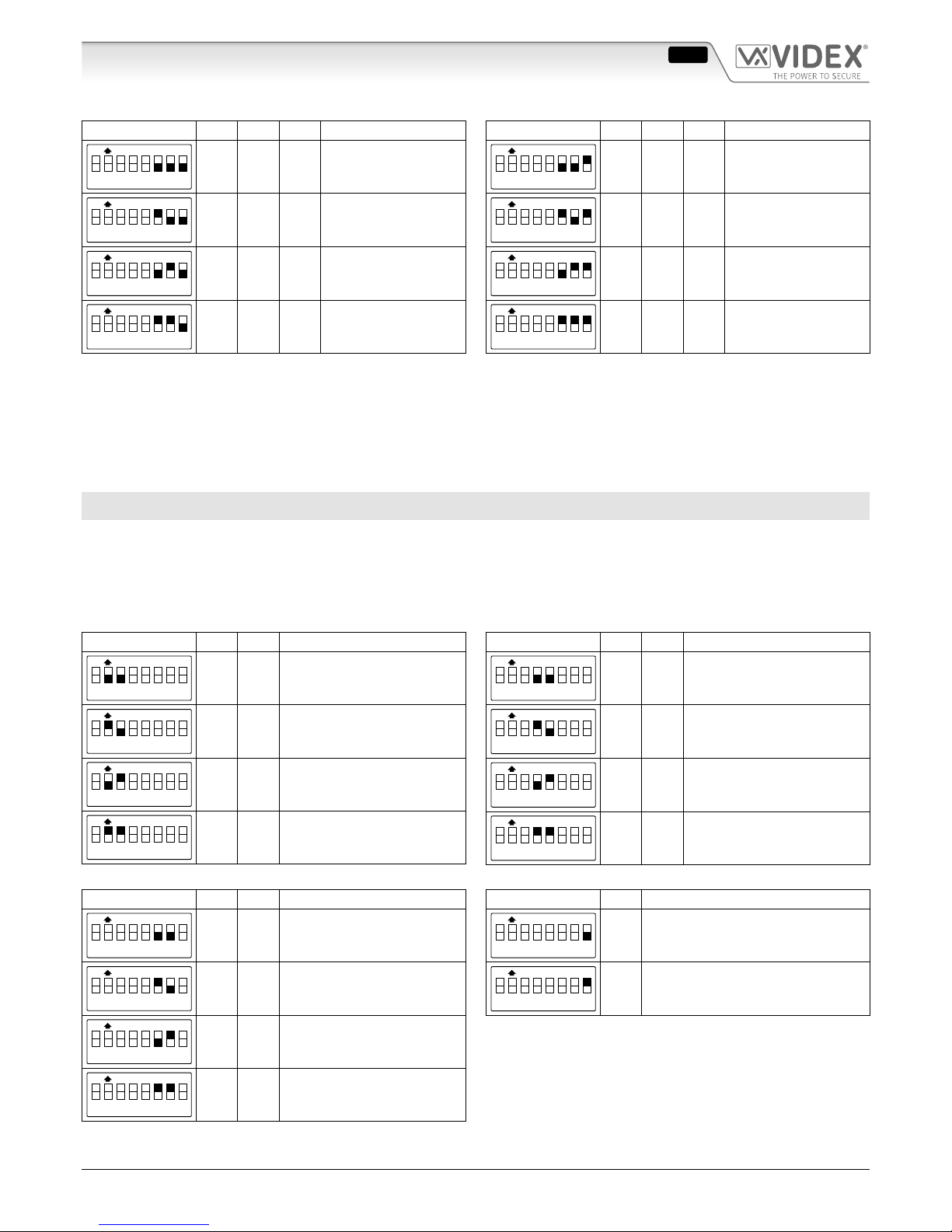
PROGRAMMING THE DEVICE NUMBER
Switch Nr. 6 Nr.7 Nr.8 Setting Up Switch Nr. 6 Nr.7 Nr.8 Setting Up
ON
1 2 3 4 5 6 7 8
OFF OFF OFF = 1
ON
1 2 3 4 5 6 7 8
OFF OFF ON = 5
ON
1 2 3 4 5 6 7 8
ON OFF OFF = 2
ON
1 2 3 4 5 6 7 8
ON OFF ON = 6
ON
1 2 3 4 5 6 7 8
OFF ON OFF = 3
ON
1 2 3 4 5 6 7 8
OFF ON ON = 7
ON
1 2 3 4 5 6 7 8
ON ON OFF = 4
ON
1 2 3 4 5 6 7 8
ON ON ON = 8
The device number is used by the digital concierge to show from which entrance calls are made.
PROGRAMMING NOTES 3000 AND 900 SERIES MODE
In case of a wrong Master/Slave conguration (Dip-switch no.1), the following problems can occur:
a. If the unit should be a Master but is congured as a Slave, the error is signalled by an acoustic intermittent signal until the problem is resolved;
b. If the unit must be Slave but is congured as Master, the impedance of the system will have a lack of balance, causing feedback (“Larsen” eect).
When a system uses a concierge unit Art.2210-1 the push button combined to the Phone ID 1 (only with the switches.2 & 3
OFF = ID Group from 1 to 64) is reserved to call the concierge in day or night mode.
WITH THE TWO JUMPERS IN LOWER POSITION “316X” TO WORK ONLY WITH INTERCOMS ART.3161 & ART.3162, THE 8
WAY DIPSWITCH ENABLES THE FOLLOWING:
• Program the 64 push buttons group (switches 2 & 3);
• Program the number of call rings (switches 4 & 5);
• Program the conversation time (switch 6 & 7);
• Program the door opening time (switch 8);
The switch 1 is not used.
PROGRAMMING OF THE 64 PUSH BUTTONS GROUP
Switch Nr. 2 Nr.3 Setting Up
ON
1 2 3 4 5 6 7 8
OFF OFF = from 1 to 64
ON
1 2 3 4 5 6 7 8
ON OFF = from 65 to 128
ON
1 2 3 4 5 6 7 8
OFF ON = from 129 to 180
ON
1 2 3 4 5 6 7 8
ON ON = from 193 to 255
PROGRAMMING THE NUMBER OF CALL RINGS
Switch Nr. 4 Nr.5 Setting Up
ON
1 2 3 4 5 6 7 8
OFF OFF = 2
ON
1 2 3 4 5 6 7 8
ON OFF = 4
ON
1 2 3 4 5 6 7 8
OFF ON = 6
ON
1 2 3 4 5 6 7 8
ON ON = 8
PROGRAMMING THE CONVERSATION TIME
Switch Nr. 6 Nr.7 Setting Up
ON
1 2 3 4 5 6 7 8
OFF OFF = 1 minute
ON
1 2 3 4 5 6 7 8
ON OFF = 2 minutes
ON
1 2 3 4 5 6 7 8
OFF ON = 3 minutes
ON
1 2 3 4 5 6 7 8
ON ON = 4 minutes
PROGRAMMING THE DOOR OPENING TIME
Switch Nr. 8 Setting Up
ON
1 2 3 4 5 6 7 8
OFF = 2 seconds
ON
1 2 3 4 5 6 7 8
ON = 6 seconds
Art.4203 Digital to functional interface module/"2 Wire bus" system
ENG
Page 4
66250190 - V2.2 - 28/02/18
- 4 -
4000 Series
Art.4203 - Installation instructions
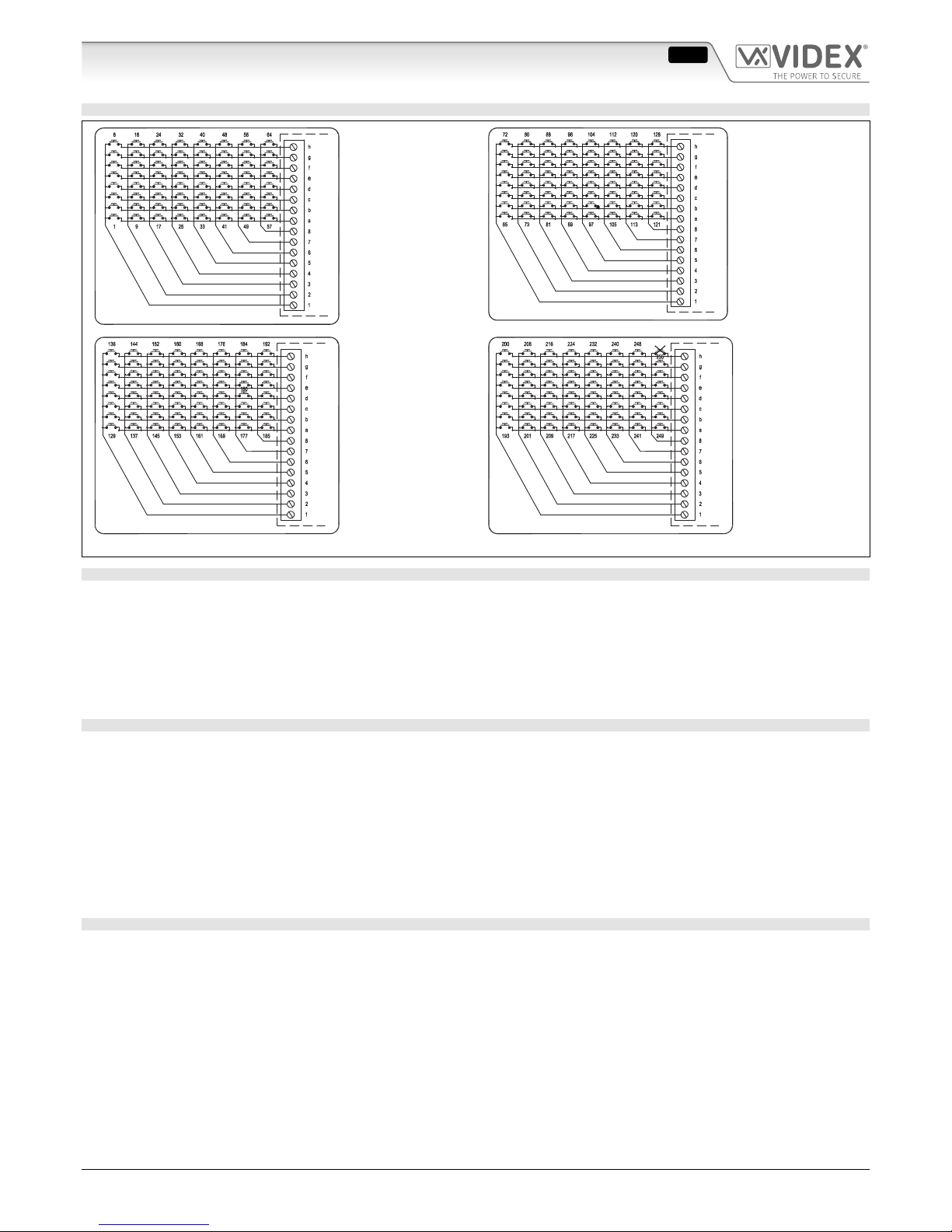
PUSH BUTTON CONNECTION
Dip-Switch n°2=OFF
n°3=OFF
or
Dip-Switch n°2=ON
n°3=ON using 900
Series
Dip-Switch n°2=ON
n°3=OFF
Dip-Switch n°2=OFF
n°3=ON (only up to
180 if set to work
with other intercoms
models)
Dip-Switch n°2=ON
n°3=ON (only when
set to work with
Art.3161 intecoms)
Fig. 3
OPERATION
Once the Art.4203 has been programmed and connected correctly, it will generate on each pressing of a push button, a code corresponding to the PHONE ID (address programmed on the 8 way dip-switch inside each telephone) of the telephone being called.
TO CALL A USER
Press the relevant button to call the user: 5 quick beeps will indicate if the system is busy, otherwise the call will be signalled by a
slow intermittent acoustic signal until the call is answered, the conversation time expires (programmable time) or the call is interrupted by pressing a push button for a minimum of 2 seconds. A short intermittent acoustic signal indicates that the door is open.
If a wrong push button is pressed or if there is no answer, a new call will erase the previous one.
SPECIAL APPLICATIONS SYSTEMS USING BLOCK EXCHANGER ART.2206N
In all systems using block exchangers Art.2206N, the main entrance panels which are connected before these exchangers can only
be digital type panels because of technical reasons
In case the system operation requires that the digital panel is only enabled to call the switchboard, it is possible to connect as a main panel
one or more Art.4203 (for Art.4203 instructions) or Art.8203 (for Art.8203 instructions) with one single button only as follows:
• Blue wire connected to terminal “8”;
• Yellow wire connected to terminal “A”;
• Switch 2 on “OFF”;
• Switch 3 on “ON”.
Thanks to this conguration the panel can be set as one of the “main” panels and when the button is pressed the call is made directly
to the switchboard.
MOUNTING NOTES
We recommend completing the programming of the unit and then connect the extension front panel modules as follows:
• Connect the push buttons common connection to one of the Art.2203 terminals marked with numbers from “1” to “8”, depend-
ing on the PHONE IDs required when pressing the push buttons (for example with the dip-switches 2 and 3 both OFF, connecting
the push buttons common to terminal “1”, will enable the PHONE IDs from 1 to 8 to combine with the push buttons, while con-
necting the common to terminal “2” will enable the PHONE IDs from 9 to 16 and so on refer to Fig. 2 and Fig. 3);
• Connect each push button of the module to the Art.2203 terminals marked with the letters from “a” to “h” depending on the
PHONE ID needed to be combined with the push button (for example having dip-switches 2 and 3 both OFF and the push buttons common of the module connected to terminal “2”, connect the push button to terminal “a” to call PHONE ID 9, or “b” to call
PHONE ID 10 and so on refer to Fig. 2 and Fig. 3).
In order to achieve the correct combination between the push buttons and the relevant extensions, it is advisable to refer to the
picture at the back of the module for the correct cabling.
The digital concierge cannot be installed on systems using Art.316X intercoms.
Art.4203 Digital to functional interface module/"2 Wire bus" system
ENG
Page 5
66250190 - V2.2 - 28/02/18
- 5 -
4000 Series
Art.4203 - Installation instructions
Art.4203 Digital to functional interface module/"2 Wire bus" system
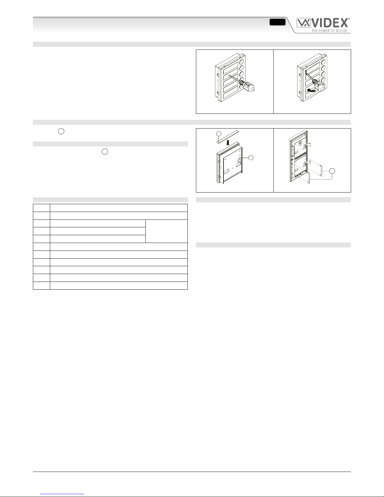
HOW TO REMOVE/INSERT THE CARD NAME HOLDER
• To avoid damage to the module front plate, mask the side that
will be in contact with the screwdriver blade;
• Insert the screwdriver (at side) into the card-holder hole as
shown in Fig. 4;
• Move the screwdriver to the left as shown in Fig. 5 to extract
the card name holder;
• Edit the card name then replace it inside the holder and ret:
insert the holder inside its housing from the left or right side
then push the other side until it clips into place.
Fig. 4 Fig. 5
ADHESIVE GASKET PLACEMENT
Apply the Y seal as shown in Fig. 6.
ANTITAMPERING LOCKS FIXING
Fit the anti-tampering locks
W
as shown in Fig. 7.
Y
G
Fig. 6
W
Fig. 7
CONNECTION TERMINALS SIGNALS
1..8 Button matrix column terminals (commons)
A..H Button matrix column terminals
NC Relay normally closed contact
MAX 24Vac/dc
2A
C Relay common contact
NO Relay normally open contact
SL Active low output (active during the call)
BSY Active low input/output (busy signal)
L BUS line data input
− BUS line ground input
+12 +12Vdc power supply input
GND Power supply ground input
TECHNICAL SPECIFICATIONS
Memory capacity: Up to 64 users
Working voltage: 13 Vdc +/- 10%
Power consumption: Stand-by: 60mA
Max: 350mA
Working Temperature: -10 +50 °C
CLEANING OF THE PLATE
Use a clean and soft cloth. Use moderate warm water or non-aggressive cleansers.
Do not use:
• abrasive liquids;
• chlorine-based liquids;
• metal cleaning products.
ENG
Page 6
66250190 - V2.2 - 28/02/18
- 6 -
Serie 4000
Art.4203 - Istruzioni di installazione
EC
A
D
F
B
Fig. 1 Fronte
H
G
L
I
M
O
N
Nero - Pulsante 4
Bianco - Pulsante 3
Rosso - Pulsante 2
Giallo - Pulsante 1Blu - Comune
Fig. 2 Retro
DESCRIZIONE
L’Art.4203 è un’unità di chiamata digitale su BUS “2 li” che permette
la connessione di pulsanti tradizionali al sistema digitale VX2200.
L’unità è alloggiata in un modulo Serie 4000 e la sua elettronica si
compone dell’interfaccia analogico-digitale e del portiere elettrico
con 0, 1, 2 o 4 pulsanti in base al modello. Le niture disponibili
per il modulo sono le stesse di tutta la Serie 4000: placca frontale
in acciaio inossidabile lucidato a specchio (nitura standard) ed in
alluminio anodizzato (aggiungere /A al codice prodotto). L’interfaccia permette il collegamento di 64 pulsanti tradizionali impiegando i moduli di chiamata standard Serie 4000: Art.4842, Art.4843,
Art.4844, Art.4845 e le relative versioni pulsanti doppi Art.4842D,
Art.4843D, Art.4844D e Art.4845D. Al numero dei pulsanti necessari alla composizione del posto esterno vanno sempre sottratti
quelli presenti nel modulo (0,1,2 o 4 in base al modello). I pulsanti
presenti nel modulo, 1, 2 o 4 (Art.4203-1, Art.4203-1D o Art.4203-2
e Art.4203-2D), sono congurati di fabbrica rispettivamente come
1° ID Citofono, come 1° e 2° o come 1°, 2°, 3° e 4° ID del gruppo di
indirizzi impostato tramite gli switch 2 e 3 del dip-switch ad 8 vie.
Operando sui li che fuoriescono dall’unità è possibile congurare
dierentemente i pulsanti del modulo. Nel caso siano necessari più
di 64 pulsanti, è possibile utilizzare più moduli per arrivare no a
150 pulsanti con citofoni e videocitofoni Serie 900, no a 180 con
la Serie 3000 (eccetto i citofoni Art.316x) e no a 255 con citofoni
Art.316x. I moduli vanno assemblati utilizzando le scatole da incasso o supercie della Serie 4000.
L’Art.4203 funziona con citofoni e videocitofoni Serie 900, Serie
3000 e con i nuovi citofoni a basso costo Art.316x.
LEGENDA
A
Altoparlante
B
LED
C
Pulsante 4 - lo nero
D
Pulsante 3 - lo bianco
E
Pulsante 2 - lo rosso
F
Pulsante 1 - lo giallo
G
Regolazione bilanciamento
H
Volume altoparlante
I
Volume microfono
L
Dip-switch a 8 vie
M
Jumper
N
Morsetteria di connessione
O
Microfono
VERSIONI DISPONIBILI
Art.4203-0
1
Art.4203-1
1
2
Art.4203-2
13
Art.4203-1D
13
4 2
Art.4203-2D
Art.4203 Modulo d'interfaccia pulsanti tradizionali/sistema "BUS 2 li"
ITA
Page 7

66250190 - V2.2 - 28/02/18
- 7 -
Serie 4000
Art.4203 - Istruzioni di installazione
LED
Il primo LED (rosso) indica, se acceso, che non è possibile eettuare la chiamata perché è in corso una chiamata o una conversazione (dall’ingresso dal quale si
sta chiamando o da un altro ingresso in caso d’ingressi multipli). Chiusa la conversazione, il LED si spegne
segnalando che è possibile fare una nuova chiamata.
Il secondo LED (rosso) indica, se acceso, che è in corso una
chiamata. Il LED si spegne alla risposta dell’utente chiamato.
Il terzo LED (verde) indica, se acceso, che è possibile
parlare con l’utente chiamato. Il LED si spegne a ne
conversazione.
Il quarto LED (giallo) contrassegnato dal simbolo , se acceso, indica che sta avvenendo l’apertura della porta. Il
LED si spegne allo scadere del tempo di apertura porta.
TABELLA PULSANTIFILI
Blu Comune pulsanti
Giallo Pulsante 1
Rosso Pulsante 2
Bianco Pulsante 3
Nero Pulsante 4
REGOLAZIONI
Bilanciamento
Previene l’eetto Larsen su conversazione audio bidirezionale.
Rif. Regolazione della fonia sul manuale tecnico
“VX2200 - Norme generali di installazione”
Volume altoparlante
Regolazione del volume dell’altopalralte.
Ruotare in senso orario per aumentare o antiorario per diminuire
Volume microfono
Regolazione del volume del microfono.
Ruotare in senso orario per aumentare o antiorario per diminuire
JUMPER
Posizione “Art.316X”
Per programmazione solo con citofoni Art.3161 e
Art.3162
Posizione “Others”
Per programmazione con citofoni Serie 900 e 3000
tranne Art.3161 e Art.3162
PROGRAMMAZIONE
La programmazione consiste nell’impostazione del dip-switch ad 10 vie e dei due jumper accessibili dalle 2 nestre sul retro del modulo.
In base all’impostazione dei 2 jumper, il dip-switch ad 8 vie assume signicati dierenti.
FUNZIONI DEL DIPSWITCH AD 8 VIE CON I DUE JUMPER VERSO L’ALTO IN POSIZIONE “OTHERS” MODALITÀ DI FUNZION
AMENTO PER L’UTILIZZO CON PRODOTTI SERIE 900 E 3000 ESCLUSI I CITOFONI ART.3161 E ART.3162:
• Programmare l’unità come Master o Slave (switch 1);
• Programmare il gruppo dei 64 pulsanti (switch 2 e 3);
• Programmare il tempo di conversazione (switch 4);
• Programmare il tempo di apertura porta (switch 5);
• Programmare il numero del dispositivo (switch 6,7,8);
CONFIGURAZIONE DELL’UNITÀ COME MASTER O SLAVE
Switch Nr. 1 Impostazione
ON
1 2 3 4 5 6 7 8
OFF = Slave
ON
1 2 3 4 5 6 7 8
ON = Master (default)
PROGRAMMAZIONE DEL GRUPPO DI 64 PULSANTI
Switch Nr. 2 Nr.3 Impostazione
ON
1 2 3 4 5 6 7 8
OFF OFF = da 1 a 64
ON
1 2 3 4 5 6 7 8
ON OFF = da 65 a 128
ON
1 2 3 4 5 6 7 8
OFF ON = da 129 a 180
ON
1 2 3 4 5 6 7 8
ON ON
= da 1 a 64
con dispositivi Serie 900
Questa programmazione stabilisce l’intervallo degli “Identicativi
Citofono” generati dalla pressione dei pulsanti collegati all’unità.
Ad esempio con i dip-switch 2 e 3 entrambi ad OFF, il pulsante
collegato tra i morsetti “1” ed “a” è abbinato all’ID CITOFONO 1,
mentre impostando i dip-switch 2 e 3 rispettivamente ad ON ed
OFF, lo stesso pulsante sarà abbinato all’ID CITOFONO 65. Il quarto
intervallo è stato previsto per l’impiego dell’unità in abbinamento
ai citofoni e videocitofoni della precedente Serie 900.
PROGRAMMAZIONE DEL TEMPO DI CONVERSAZIONE
Switch Nr. 4 Impostazione
ON
1 2 3 4 5 6 7 8
OFF = 1 minuto
ON
1 2 3 4 5 6 7 8
ON = 2 minuti
PROGRAMMAZIONE DEL TEMPO DI APERTURA PORTA
Switch Nr. 5 Impostazione
ON
1 2 3 4 5 6 7 8
OFF = 2 secondi
ON
1 2 3 4 5 6 7 8
ON = 6 secondi
Art.4203 Digital to functional interface module/"2 Wire bus" system
ITA
Page 8

66250190 - V2.2 - 28/02/18
- 8 -
Serie 4000
Art.4203 - Istruzioni di installazione
PROGRAMMAZIONE DEL NUMERO DI DISPOSITIVO
Switch Nr. 6 Nr.7 Nr.8 Impostazione Switch Nr. 6 Nr.7 Nr.8 Impostazione
ON
1 2 3 4 5 6 7 8
OFF OFF OFF = 1
ON
1 2 3 4 5 6 7 8
OFF OFF ON = 5
ON
1 2 3 4 5 6 7 8
ON OFF OFF = 2
ON
1 2 3 4 5 6 7 8
ON OFF ON = 6
ON
1 2 3 4 5 6 7 8
OFF ON OFF = 3
ON
1 2 3 4 5 6 7 8
OFF ON ON = 7
ON
1 2 3 4 5 6 7 8
ON ON OFF = 4
ON
1 2 3 4 5 6 7 8
ON ON ON = 8
Il numero di dispositivo viene utilizzato dal centralino di portineria per indicare da quale posto esterno è arrivata la chiamata.
NOTE DI PROGRAMMAZIONE MODO SERIE 3000 E 900
Nel caso di una errata congurazione Master/Slave (Dip-switch nr.1), si possono vericare i seguenti inconvenienti:
a. se l’unità deve essere Master, ma viene congurata come Slave, viene segnalato l’errore con un segnale acustico intermittente no
alla risoluzione del problema;
b. se l’unità deve essere Slave, ma viene congurata come Master, si avrà uno squilibrio dell’impedenza dell’impianto che si potreb-
be manifestare attraverso dei rumori (eetto “Larsen”); i rumori spariranno alla risoluzione del problema.
Se nel sistema è presente il centralino digitale Art.2210-1, il pulsante al quale è associato l’ID citofono 1 (valido solo con gli switch
nr.2,3 ad OFF = Gruppo di ID da 1 a 64) è riservato alla sua chiamata.
FUNZIONI DEL DIPSWITCH AD 8 VIE CON I DUE JUMPER ENTRAMBI VERSO IL BASSO “316X” MODALITÀ DI FUNZIONA
MENTO PER L’UTILIZZO CON CITOFONI ART.3161 E ART.3162:
• Programmare il gruppo dei 64 pulsanti (switch 2 e 3);
• Programmare il numero di squilli in chiamata (switch 4 e 5);
• Programmare il tempo di conversazione (switch 6 e 7);
• Programmare il tempo di apertura porta(switch 8).
Lo switch 1 non è utilizzato.
PROGRAMMAZIONE DEL GRUPPO DI 64 PULSANTI
Switch Nr. 2 Nr.3 Impostazione
ON
1 2 3 4 5 6 7 8
OFF OFF = da 1 a 64
ON
1 2 3 4 5 6 7 8
ON OFF = da 65 a 128
ON
1 2 3 4 5 6 7 8
OFF ON = da 129 a 180
ON
1 2 3 4 5 6 7 8
ON ON = da 193 a 255
PROGRAMMAZIONE DEL NUMERO DI SQUILLI
Switch Nr. 4 Nr.5 Impostazione
ON
1 2 3 4 5 6 7 8
OFF OFF = 2
ON
1 2 3 4 5 6 7 8
ON OFF = 4
ON
1 2 3 4 5 6 7 8
OFF ON = 6
ON
1 2 3 4 5 6 7 8
ON ON = 8
ROGRAMMAZIONE DEL TEMPO DI CONVERSAZIONE
Switch Nr. 6 Nr.7 Impostazione
ON
1 2 3 4 5 6 7 8
OFF OFF = 1 minuto
ON
1 2 3 4 5 6 7 8
ON OFF = 2 minuti
ON
1 2 3 4 5 6 7 8
OFF ON = 3 minuti
ON
1 2 3 4 5 6 7 8
ON ON = 4 minuti
PROGRAMMAZIONE DEL TEMPO APERTURA PORTA
Switch Nr. 8 Impostazione
ON
1 2 3 4 5 6 7 8
OFF = 2 secondi
ON
1 2 3 4 5 6 7 8
ON = 6 secondi
Art.4203 Digital to functional interface module/"2 Wire bus" system
ITA
Page 9

66250190 - V2.2 - 28/02/18
- 9 -
Serie 4000
Art.4203 - Istruzioni di installazione
COLLEGAMENTO PULSANTI
Dip-Switch n°2=OFF
n°3=OFF oppure
Dip-Switch n°2=ON
n°3=ON con
dispositivi Serie 900
Dip-Switch n°2=ON
n°3=OFF
Dip-Switch n°2=OFF
n°3=ON (solo no a
180 se impostato per
funzionare con altri
modelli di citofoni)
Dip-Switch n°2=ON
n°3=ON
(solo quando
impostato per
lavorare con citofoni
Art.3161)
Fig. 3
FUNZIONAMENTO
L’Art. 4203, dopo le opportune impostazioni e gli adeguati collegamenti dei pulsanti, genera, alla pressione di ciascun pulsante
collegato, un codice che corrisponde all’ID CITOFONO (l’indirizzo programmato sul dip-switch ad 8 vie interno alle periferiche) del
citofono o videocitofono situato all’interno dell’appartamento che si desidera chiamare.
PER CHIAMARE UN UTENTE
Premere il pulsante relativo all’utente che si desidera chiamare: se il sistema è occupato sarà segnalato da 5 beep rapidi, altrimenti
la chiamata sarà scandita da un segnale acustico a lenta intermittenza, interrotto dalla risposta dell’utente o dallo scadere dell’intervallo del tempo di conversazione (tempo programmabile) o dalla pressione prolungata (2sec circa) di un pulsante della tastiera.
L’apertura della porta è segnalata da un breve segnale acustico intermittente. In caso di pressione di un tasto sbagliato o di mancata
risposta, una nuova chiamata può cancellare quella precedente.
APPLICAZIONI SPECIALI SISTEMI CHE FANNO USO DEGLI SCAMBIATORI DI BLOCCO ART.2206N
Nei sistemi che fanno uso degli scambiatori di blocco Art.2206N, i posti esterni principali, quelli connessi cioè a monte degli scambiatori,
possono essere solamente di tipo digitale per questioni di natura tecnica. Qualora la modalità operativa dell’impianto preveda che il posto
esterno sia abilitato a chiamare solo il centralino di portineria, è possibile collegare come posto esterno “main” uno o più (Art.4203 sulle
istruzioni del Art.4203 o Art.8203 sulle istruzioni dell’Art.8203) in congurazione pulsante singolo e impostati come specicato di seguito:
• Filo Blu collegato al morsetto “8”;
• Filo Giallo collegato al morsetto “A”;
• Switch 2 in posizione OFF;
• Switch 3 in posizione ON.
Con questa impostazione, il posto esterno può essere installato come uno dei posti esterni “main” e quando il pulsante viene premuto, la chiamata va diretta al centralino di portineria.
NOTE DI INSTALLAZIONE
Si consiglia innanzi tutto di provvedere alla programmazione e successivamente di procedere al collegamento dei moduli pulsantiera come indicato di seguito:
• Collegare il comune pulsanti del modulo ad uno dei morsetti dell’Art.2203 contrassegnati dai numeri da “1” ad “8” in base agli
identicativi citofono che si desidera vengano generati dai pulsanti (es. con i Dip-switch nr.2 e 3 entrambi ad OFF e collegando
il comune pulsanti al morsetto “1”, sono disponibili gli ID CITOFONO da 1 ad 8, collegandolo al “2” quelli da 9 a 16 e cosi via come
mostrato in Fig. 2 e Fig. 3);
• Collegare ciascun pulsante del modulo ad uno dei morsetti contrassegnati dalle lettere da “a” ad “h” in base all’ID CITOFONO che si desidera associare al pulsante (es. con i Dip-switch nr.2 e 3 entrambi ad OFF e con il comune pulsanti connesso al morsetto “2”, collegare
il pulsante al morsetto “a” per avere l’ID CITOFONO 9, al “b” per il 10 e cosi via come mostrato in Fig. 2 e Fig. 3).
Per avere la giusta corrispondenza tra i pulsanti ed i relativi interni, si consiglia di fare riferimento alla gura presente sul retro del modulo.
I sistemi che utilizzano citofoni 316x non permettono l’impiego del centralino di portineria.
Art.4203 Digital to functional interface module/"2 Wire bus" system
ITA
Page 10

66250190 - V2.2 - 28/02/18
- 10 -
Serie 4000
Art.4203 - Istruzioni di installazione
Art.4203 Digital to functional interface module/"2 Wire bus" system
RIMOZIONE/INSERIMENTO DEL PORTACARTELLINO
• Per evitare ammaccature della placca frontale, proteggere il
lato che verrà in contatto con la lama del cacciavite utilizzando una striscia di nastro isolante;
• Inserire il cacciavite (lato piatto della lama) nell’apposita fessura del porta cartellino come mostrato in Fig. 4;
• Fare leva con il cacciavite come mostrato in Fig. 5 per rimuovere il
porta-cartellino (fare attenzione a non ammaccare la placca);
• Modicare il cartellino e riporlo all’interno del porta-cartellino quindi riposizionare lo stesso al suo posto inserendolo nel
suo alloggiamento dal lato destro o sinistro e premendo il lato
rimasto libero no all’aggancio (compiendo un movimento
contrario a quello fatto per estrarlo).
Fig. 4 Fig. 5
APPLICAZIONE GUARNIZIONE ADESIVA
Applicare la guarnizione adesiva Y come mostrato in Fig. 6.
INSERIMENTO FERMI ANTIEFFRAZIONE
Inserire i fermi anti-erazione
W
come mostrato in Fig. 7.
Y
G
Fig. 6
W
Fig. 7
SEGNALI MORSETTERIA DI CONNESSIONE
1..8 Matrice pulsanti morsetti colonne (comuni)
A..H Matrice pulsanti morsetti righe
NC Relé contatto normalmente chiuso
MAX 24Vac/dc
2A
C Relé contatto comune
NO Relé contatto normalmente aperto
SL Uscita di tipo attivo basso (attiva durante la chiamata)
BSY Ingresso/Uscita di tipo attivo basso (segnale busy)
L Linea BUS ingresso dati
− Linea BUS ingresso massa
+12 Ingresso alimentazione +12Vdc
GND Ingresso massa di alimentazione
SPECIFICHE TECNICHE
Capacità di memoria: no a 64 utenti
Tensione di lavoro: 13 Vdc +/- 10%
Assorbimento massimo: A riposo: 60mA
Max: 350mA
Temperatura di funzionamento: -10 +50 °C
PULIZIA DELLA PLACCA
Usare un panno morbido e pulito. Usare acqua tiepida o un detergente non aggressivo.
Non usare:
• prodotti abrasivi;
• prodotti contenenti cloro;
• prodotti per la pulizia dei metalli.
ITA
Page 11

66250190 - V2.2 - 28/02/18
- 11 -
Page 12

66250190 - V2.2 - 28/02/18
- 12 -
Page 13

66250190 - V2.2 - 28/02/18
- 13 -
Page 14

66250190 - V2.2 - 28/02/18
- 14 -
Page 15

66250190 - V2.2 - 28/02/18
- 15 -
Page 16

66250190 - V2.2 - 28/02/18
- 16 -
Page 17

66250190 - V2.2 - 28/02/18
- 17 -
Page 18

66250190 - V2.2 - 28/02/18
- 18 -
Page 19

66250190 - V2.2 - 28/02/18
- 19 -
Page 20

MANUFACTURER
FABBRICANTE
FABRICANT
FABRICANTE
FABRIKANT
VIDEX ELECTRONICS S.P.A.
Via del Lavoro, 1
63846 Monte Giberto (FM) Italy
Tel (+39) 0734 631669
Fax (+39) 0734 632475
www.videx.it - info@videx.it
CUSTOMER SUPPORT
SUPPORTO CLIENTI
SUPPORTS CLIENTS
ATENCIÓN AL CLIENTE
KLANTENDIENST
VIDEX ELECTRONICS S.P.A.
www.videx.it - technical@videx.it
Tel: +39 0734-631669
Fax: +39 0734-632475
UK Customers only:
VIDEX SECURITY LTD
www.videxuk.com
Tech Line: 0191 224 3174
Fax: 0191 224 1559
Main UK oce:
VIDEX SECURITY LTD
1 Osprey Trinity Park
Trinity Way
LONDON E4 8TD
Phone: (+44) 0870 300 1240
Fax: (+44) 020 8523 5825
www.videxuk.com
marketing@videxuk.com
Northern UK oce:
VIDEX SECURITY LTD
Unit 4-7
Chillingham Industrial Estate
Chapman Street
NEWCASTLE UPON TYNE - NE6 2XX
Tech Line: (+44) 0191 224 3174
Phone: (+44) 0870 300 1240
Fax: (+44) 0191 224 1559
Greece oce:
VIDEX HELLAS Electronics
48 Filolaou Str.
11633 ATHENS
Phone: (+30) 210 7521028
(+30) 210 7521998
Fax: (+30) 210 7560712
www.videx.gr
videx@videx.gr
Danish oce:
VIDEX DANMARK
Hammershusgade 15
DK-2100 COPENHAGEN
Phone: (+45) 39 29 80 00
Fax: (+45) 39 27 77 75
www.videx.dk
videx@videx.dk
Benelux oce:
NESTOR COMPANY NV
E3 laan, 93
B-9800 Deinze
Phone: (+32) 9 380 40 20
Fax: (+32) 9 380 40 25
www.videx.be
info@videx.be
Dutch oce:
NESTOR COMPANY BV
Business Center Twente (BCT)
Grotestraat, 64
NL-7622 GM Borne
www.videxintercom.nl
info@videxintercom.nl
El producto lleva la marca CE que demuestra su conformidad y puede ser
distribuido en todos los estados miembros de la unión europea UE.
Este producto cumple con las Directivas Europeas 2014/30/EU (EMC);
2014/35/EU (LVD); 2011/65/EU (RoHS): marca CE 93/68/EEC.
Het product heeft de CE-markering om de conformiteit ervan aan te tonen en
is bestemd voor distributie binnen de lidstaten van de EU zonder beperkin-
gen. Dit product volgt de bepalingen van de Europese Richtlijnen 2014/30/EU
(EMC); 2014/35/EU (LVD); 2011/65/EU (RoHS): CE-markering 93/68/EEG.
Le produit est marqué CE à preuve de sa conformité et peut être distribué
librement à l’intérieur des pays membres de l’union européenne EU.
Ce produit est conforme aux directives européennes 2014/30/EU (EMC) ;
2014/35/EU (LVD) ; 2011/65/EU (RoHS): marquage CE 93/68/EEC.
The product is CE marked demonstrating its conformity and is for distribution
within all member states of the EU with no restrictions. This product follows
the provisions of the European Directives 2014/30/EU (EMC); 2014/35/EU
(LVD); 2011/65/EU (RoHS): CE marking 93/68/EEC.
Il prodotto è marchiato CE a dimostrazione della sua conformità e può essere
distribuito liberamente all’interno dei paesi membri dell’Unione Europea UE.
Questo prodotto è conforme alle direttive Europee: 2014/30/UE (EMC);
2014/35/UE (LVD); 2011/65/UE (RoHS): marcatura CE 93/68/EEC.
 Loading...