

Page 1
15
3600 SERIES VIDEOPHONES
VIDEOCITOFONI SERIE 3600
161
178
218
46
62
FOR TRADITIONAL VIDEO SYSTEMS USING COAX VIDEO SIGNAL
OR BALANCED VIDEO SIGNAL ART.3618
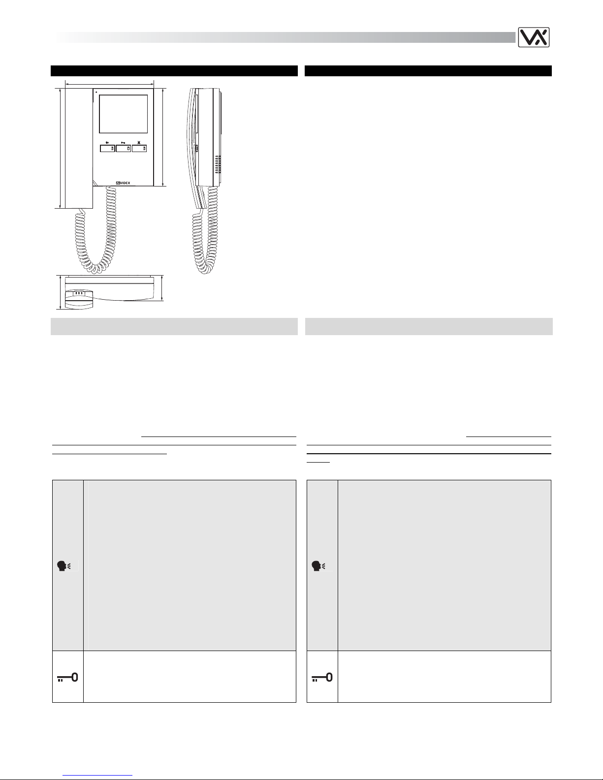
Videophone (with hands free facility) using 3.5” full colour active matrix
LCD monitor for traditional video door entry systems using coax cable or
two wire (balanced video) to bring the video signal.
Are available “door open” , “answer/camera recall/push to talk”, “privacy/call reject/service” buttons plus 3 LED’s give visual signalling relative to
the videophone operation.
Controls: loudspeaker volume, call tone volume, contrast, brightness and
hue.
Programmable privacy duration, melody, number of rings, door opening
time and video mode. Input for electronic call tone.
The Art.3618 is for surface mount (requires the Art.5980 connection board
plus wall mounting plate) The Art.3618 can be used in all the systems
where are used the Art.3411, 3412, 5418 or 5412 but requires and additional wire for 12Vdc power supply.
Push buttons
1. On an incoming call, operation of this button allows the
user to answer and converse with the visitor in hands
free mode. The relevant LED will illuminate. You can answer also by the handset.
2. If operated when system is in standby (no Call) camera
recall will be activated and the relevant LED will illuminate.
3. When in conversation (monitor on), momentary operation of the button will switch the videophone off. The videophone will also automatically switch off after a time
delay if the button is not pressed. The relevant LED will
switch off.
4. When in conversation (monitor on), pressing and holding
the button for more than 3 seconds will switch the videophone into SIMPLEX speech mode. Press and hold the
button to speak to the caller (The LED will flash rapidly),
release the button to listen (The LED will flash slowly). If
the button is not pressed for 10 seconds the videophone
will switch off. The videophone will revert to duplex
speech when another call is made.
During a call, operation of this button will activate the “door
open” relay. On the display (top centre) will be signalled the
door opening. The LED of the button will illuminate if terminal
19 has been properly connected i.e. to a door contact to monitor the door status.
PER SISTEMI VIDEO TRADIZIONALI CON SEGNALE VIDEO
COASSIALE O BILANCIATO ART.3618
Videocitofono (con funzione viva-voce) a colori con monitor LCD TFT da
3,5” per sistemi videocitofonici standard operanti tramite cavo coassiale o
segnale video bilanciato (no sistemi “4+1” video). Sono disponibili 3 pulsanti con molteplici funzioni: “apri-porta”, “risposta/auto-accensione/premi
per parlare”, “privacy/rifiuto chiamata/servizio”. 3 LED forniscono informazioni circa il funzionamento del videocitofono.
Regolazioni: volume altoparlante, volume del tono di chiamata, luminosità,
contrasto e saturazione.
Durata privacy, numero di squilli, tempo d’apertura porta e modo video
programmabili. Ingresso per chiamata tramite nota elettronica.
L’Art.3618 è per il montaggio da superficie (richiede l’Art.5980 scheda di
connessione più piastra di fissaggio a parete), Il videocitofono 3618 può
essere impiegato negli stessi sistemi in cui sono utilizzati i videocitofoni
3411, 3412, 5418 o 5412, ma richiede un filo addizionale di alimentazione
12Vdc.
Pulsanti
1. Premendo questo pulsante alla ricezione della chiamata
è possibile avviare la conversazione con il visitatore in
modo viva-voce. Il relativo LED si accende. La risposta
può avvenire alternativamente tramite cornetta.
2. Ad impianto spento, premere il pulsante per eseguire
l’auto-accensione. Il relativo LED si accende.
3. Durante una conversazione (mon itor acceso), la rapida
pressione di questo tasto spegne l’impianto. In ogni caso
lo spegnimento a tempo è automatico anche se non viene premuto il pulsante. Il relativo LED si spegne.
4. Durante una con versazione (monitor acceso), premendo
il pulsante per più di 3 secondi, il videocitofono passa
nel modo trasmissione ad una via: tenere premuto il pulsante per parlare con l’esterno (il LED lampeggia rapidamente), rilasciare il pulsante per ascoltare il visitatore
(il LED lampeggia lentamente). Se il tasto non viene
premuto per 10 secondi il videocitofono si spegne. Il videocitofono torna al funzionamento normale alla successiva accensione.
La pressione di questo pulsante durante una chiamata o una
conversazione permette di aprire la porta. L’apertura è segnalata dall’emissione di un bip e da una icona visualizzata
nella parte alta centrale del display. Il LED del pulsante si
accenderà se il morsetto 19 è opportunamente collegato ad
esempio per monitorare lo stato della porta.
Art.3618
Page 2
16
1. During a call, press this button to reject the call.
2. When the system is in stand-by, short pressing of this
button enables / disables the privacy service. The relevant LED will illuminate when the privacy service is enabled. When privacy is enabled calls will not be received.
3. When the system is in stand-by, press this button until
the videophone switches on emitting a beep to enter into
the programming menu that allows to set the privacy duration, the call tone volume, the melody selection, the
number of rings and the door opening time.
4. During a conversation, press this button to enter the adjustment menu that allows to set the speech volume, the
brightness, the contrast and the hue.
1. Premere questo pulsante durante la ricezione di una
chiamata per rifiutare la chiamata.
2. Quando il sistema è in stand-by, una rapida pressione di
questo pulsante abilita / disabilita il servizio privacy. Il relativo LED si accende quando il servizio è attivo. Con il
servizio attivo le chiamate non vengono ricevute.
3. Quando il sistema è in stand-by, premere e tenere premuto questo pulsante fino a che il videocitofono si accende emettendo un bip per entrare nel menù di programmazione. Il menù permette di impostare la durata
della privacy, il volume del tono di chiamata, la suoneria,
il numero di squilli e il tempo di apertura porta.
4. Durante una conversazione, premere questo pulsante
per entrare nel menù di regolazione che permette di impostare il volume della fonia, la luminosità, il contrasto e
la saturazione.
Controls & Programming
The adjustments and settings are carried out through the two OSD menus
that are described below. For video mode setup (coax or balanced) operate the 4 way dip switch on the rear side of the videophone.
The videomonitor has two different menus for programming and adjustment functions:
1. One menu operates when the system is in stand-by and allows to
set:
The privacy duration;
The melody volume;
The melody type;
The number of rings;
The door opening time;
2. The second menu operates when the system is turned ON (during a
conversation or a camera recall) and allows to set;
Speech volume;
Brightness;
Contrast;
Hue;
Menu 1
When the system is in stand-by (monitor turned OFF) press and hold
pressed the “
” button until the monitor switches emitting a beep to
enter the programming menu;
The OSD menu appears on the display: the top of the screen shows
“menu” followed by the available function icons, the bottom of the
screen shows the currently selected function value on the left, the
currently selected function icon in the middle and the next function
icon on the right side.
The first function available is the privacy duration (max 20 hours):
press as many times or hold pressed the “
” button to increase or
the “
” button to decrease the duration of a half an hour each step
(signalled by a beep).
Press the “
” button to store the new value and to enter the following
programming function.
The second function is the melody volume: press as many times or
hold pressed the “
” button to increase or the “ ” button to de-
crease the melody volume level (signalled by a beep).
Press the “
” button to store the new value and to enter the following
programming function.
The third function is the melody type: press the “
” button to hear
and select the previous melody or the “
” button to hear and select
the following melody.
Press the “
” button to store the new value and to enter the following
programming function.
The fourth programming function is the number of rings (max 9):
press as many times or hold pressed the “
” button to increase or
the “
” button to decrease the number of rings.
Press the “
” button to store the new value and to enter the following
programming function
The fifth programming function is the door opening time (max 99 se-
conds): press as many times or hold pressed the “
” button to in-
crease or the “
” button to decrease the number of rings.
Press the “
” button to store the new value and exit the programming
menu, the monitor turns OFF.
Regolazioni e Programmazioni
Le possibili regolazioni ed impostazioni vengono effettuate tramite i due
menù OSD di seguito descritti. Per la modalità video (coassiale o bilanciato) l’impostazione avviene tramite il dip-switch a 4 vie presente sul retro
del videocitofono.
Il videocitofono ha due differenti menù per operazioni di programmazione
e regolazione:
1. Un menù viene attivato dalla condizione di stand-by e consente di
impostare:
La durata della “privacy”;
Il volume della suoneria;
Il tipo di suoneria;
Il numero di squilli;
Il tempo di apertura porta;
2. Il secondo menù è accessibile quando il videocitono è in funzione
(durante una conversazione o auto-accensione) e consente di impostare:
Il volume della fonia;
La luminosità;
Il Contrasto;
La saturazione;
Menù 1
Per entrare nel menù di programmazione, con il sistema a riposo
(monitor spento), premere e tenere premuto il pulsante “
” fino a che
il videocitofono non si accende emettendo un bip.
Il monitor si accende mostrando il menù OSD: la parte superiore del-
lo schermo riporta la scritta “menù” seguita dall’icona della funzione
selezionata mentre la parte inferiore indica a sinistra il valore della
funzione selezionata, al centro l’icona della funzione selezionata e a
destra l’icona della successiva funzione disponibile.
La prima programmazione è la durata della privacy (massimo 20
ore): premere ripetutamente o tenere premuto il pulsante “
” per
incrementare o il pulsante “
” per decrementare la durata di mezzo-
ra ad ogni step (segnalato da un bip).
Premere il pulsante “
” per memorizzare il nuovo valore e accedere
alla programmazione successiva.
La seconda programmazione è il volume della suoneria: premere
ripetutamente o tenere premuto il pulsante “
” per incrementare o
il pulsante “
” per decrementare il volume della suoneria ad ogni
step (segnalato da un bip).
Premere il pulsante “
” per memorizzare il nuovo valore e accedere
alla programmazione successiva.
La terza programmazione è il tipo di suoneria: premere il pulsante
“
” per ascoltare e selezionare la suoneria precedente o il pulsan-
te “
” per ascoltare e selezionare la suoneria successiva.
Premere il pulsante “
” per memorizzare il nuovo valore e accedere
alla programmazione successiva.
La quarta programmazione è il numero di squilli (max 9): premere
ripetutamente o tenere premuto il pulsante “
” per incrementare o
il pulsante “
” per decrementare il numero di squilli.
Premere il pulsante “
” per memorizzare il nuovo valore e accedere
alla programmazione successiva.
La quinta ed ultima programmazione è il tempo d’apertur a po rta (m a x
99 secondi): premere ripetutamente o tenere premuto il pulsante
“
” per incrementare o il pulsante “ ” per decrementare il numero
di secondi.
Premere il pulsante “
” per memorizzare il nuovo valore e uscire dal-
la programmazione, il videocitofono si spegne.
Page 3

17
Menu 2
When the monitor is turned ON (c onversation or camera recall) press
the “
” button to enter the adjustment menu.
The OSD menu appears on the display: the top of the screen shows
“menu” followed by the allowed function icons, the bottom of the
screen shows the currently selected function value on the left, the
currently selected function icon in the middle and the next function
icon on the right side.
The first adjustment is the speec h volume: press as many times or
hold pressed the “
” button to increase or the “ ” button to de-
crease the speech volume level (signalled by a beep).
Press the “
” button to store the new value and to enter the following
programming function.
The second adjustment is the brightness: press as many times or
hold pressed the “
” button to increase or the “ ” button to de-
crease the brightness level (signalled by a beep).
Press the “
” button to store the new value and to enter the following
programming function.
The third adjustment is the contrast: press as many times or hold
pressed the “
” button to increase or the “ ” button to decrease
the contrast level (signalled by a beep).
Press the “
” button to store the new value and to enter the following
programming function.
The fourth and last adjustment is the hue: press as many times or
hold pressed the “
” button to increase or the “ ” button to de-
crease the hue level (signalled by a beep).
Press the “
” button to store the new value and exit the programming
menu the monitor goes back to shown standard messages for conversation
Menù 2
Quando il sistema è acceso (conversazione o auto-accensione) pre-
mere il pulsante “
” per accedere al menù di regolazione.
Il menù OSD si attiva: la parte superiore dello schermo riporta la
scritta “menù” seguita dall’icona della funzione selezionata mentre la
parte inferiore indica a sinistra il valore della funzione selezionata, al
centro l’icona della funzione selezionata e a destra l’icona della successiva funzione disponibile.
La prima regolazione è il volume della fonia: premere ripetutamente o
tenere premuto il pulsante “
” per incrementare o il pulsante “ ”
per decrementare il volume della fonia ad ogni step (segnalato da un
bip).
Premere il pulsante “
” per memorizzare il nuovo valore e accedere
alla programmazione successiva.
La seconda funzione è la luminosità: premere ripetutamente o tenere
premuto il pulsante “
” per incrementare o il pulsante “ ” per decrementare il livello della luminosità ad ogni step (segnalato da un
bip).
Premere il pulsante “
” per memorizzare il nuovo valore e accedere
alla programmazione successiva.
La terza funzione è il contrasto: premere ripetutamente o tenere
premuto il pulsante “
” per incrementare o il pulsante “ ” per decrementare il contrasto ad ogni step (segnalato da un bip).
La quarta ed ultima funzione è la saturazione: pre mere ripetutame nte
o tenere premuto il pulsante “
” per incrementare o il pulsante “ ”
per decrementare il livello di saturazione ad ogni step (segnalato da
un bip).
Premere il pulsante “
” per memorizzare il nuovo valore ed uscire
dalla programmazione, il monitor torna a mostrare i messaggi standard della conversazione.
Modo Video
Switch 1,2 Modo
Coassiale
Bilanciato
75 Ohm Video Termination
Switches 3,4 Termination
Enabled
Disabled
Modo Video
Switch 1,2 Modo
Coassiale
Bilanciato
Terminazione video 75 Ohm
Switch 3,4 Terminazione
Abilitata
Disabilitata
Terminals and relevant signals
The table that follow shows the signals available on the terminals (from 1
to 20) of the PCB supplied with the Art.5980 relative to the Art.3618 videomonitor.
Morsetti e relativi segnali
La tabella che segue mostra i segnali presenti sui morsetti della scheda di
connessione (1..20), inclusa nell’Art.5980, relativamente al videocitofoni
Art.3618.
ART.3618 SIGNALS ON TERMINALS OF Art.5980 ART.3618 SEGNALI MORSETTIERA Art.5980
Signal Description
Segnale
Signal
Morsetto
Art.5980
Terminal
Descrizione Segnale
+20V power input
+20V 1 Ingresso +20V
+20V power input
+20V 2 Ingresso +20V
Ground
GND 3 Massa
Ground
GND 4 Massa
Coax = V input, Balanced video = V2 input
V2/V 5 Coax = Ingresso V, Video Bilanciato = ingresso V2
Balanced video signal V1 input
V1 6 Ingresso segnale video bilanciato V1
Speech line output from handset’s microphone
3 7 Uscita linea fonica dal microfono della cornetta
Camera recall signal output
T 8 Uscita segnale di auto-accensione
Local bell input (active low)
LB 9 Ingresso per chiamata di piano (attivo basso)
Door open signal output
5 10 Uscita comando apri-porta
11
SB 12
13
14
+12V output to supply the video distributor Art.894/894N (coaxial video signal mode)
+VD 15
+12Vdc per alimentare il distributore video Art.894/894N in
modo video coassiale
Speech line input toward the handset’s loudspeaker
4 16 Speech line input toward the handset’s loudspeaker
+12Vdc stabilized output
12VO 17 Uscita stabilizzata +12Vdc
+12Vdc input
12VI 18 Ingresso di alimentazione +12Vdc
+12Vdc door open / auxiliary LED
LD 19 Ingresso di alimentazione +12Vdc LED porta aperta / ausiliare
Call tone input
C 20 Ingresso nota di chiamata
Table 7
Tabella 7
Page 4

18
ART.3618 WALL MOUNTING ART.3618 FISSAGGIO A PARETE
135cm
Fig.1
a
a
a
b
c
c
f
f
f
f
g
e
d
b
b
b
a
Fig.2
A
B
h
i
l
m
m
m
m
c
Fig.3
n
Fig.4
Cables must be fed throu gh the o pening “e ” (Fig. 2A) of the mounting
plate “c”, which should be fitted approximately 135cm from finished
floor level as shown in Fig 1;
Place the mounting plate “c ” against the wall feeding the wire group
“d” through opening “e” of the mounting plate and mark the fixing
holes “a” (Fig. 2A)
Drill the fixing holes “a”, insert the wall plugs “b” then with the cables
threaded through opening “e” fix the mounting plate “c” to the wall
with the 4 screws provided “f” (Fig. 2A).
Hook the pcb connection board “g” to the mounting plate “c ”as shown
in Fig2B and connect the wires (using the screwdriver provided) to
the terminals as shown in the diagram provided;
Once the wires are connected, hook the videophone “h” to the
Mounting plate “c” as shown in Fig. 3.
Connect the Plug “i” on the ribbon cable from the videophone to
the plug “l” on the PCB connection board “g”;
Place the videophone “h” against the 4 hooks “m” on the mount-
ing plate “c” (in line with the 4 openings “n” on the rear side of
the videophone Fig. 4) and push down as suggested by the
pointers in Fig. 3, the videophone will lock into place;
To remove the videophone, hold it firmly and push the unit in an up-
ward direction until the videophone “h” unlocks from the mounting
plate “c”
Dovendo passare attraverso la fessura “e” (fig.2A) della placca di
fissaggio a parete, consigliamo di canalizzare i conduttori in maniera
tale da lasciare 135cm circa tra la parte inferiore della scheda di fissaggio ed il pavimento finito come mostrato in figura 1;
Appoggiare la piastra di fissaggio “c” alla parete facendo passare il
gruppo di fili “d” attraverso l’apertura “e” della stessa e prendere i riferimenti per i fori di fissaggio “a” (fig.2A);
Eseguire i fori “a”, inserire al loro interno i tasselli ad espansione “b” e
dopo aver fatto passare il gruppo di fili “d” attraverso l’apertura “e”
fissare la piastra “c” alla parete tramite le viti “f” fornite a corredo
(Fig.2A);
Agganciare la scheda di connessione “g” alla placca di fissaggio “c”
come mostrato in figura 2B e procedere alla connessione dei fili alla
morsettiera (in accordo con lo schema fornito) tramite il giravite (lama
lato a taglio) fornito a corredo;
Collegati i fili, agganciare il videocitofono “h” alla piastra “c” come
mostrato in figura 3:
inserire il connettore “i” del cavo flat che fuoriesce dal retro del
videocitofono nel connettore “l” della scheda di connessione
(Fig.3),
avvicinare il videocitofono alla placca di fissaggio facendo corri-
spondere le aperture “n” (Fig.4) ai ganci “m” (Fig.3) quindi spingere il videocitofono verso il basso fino all’aggancio come suggerito dalle frecce in figura 3.
Per rimuovere il videocitofono, tenendolo saldamente spingerlo verso
l’alto fino allo sblocco.
Technical Specification Specifiche Tecniche
Voltages
Videophone 20Vdc (+2-5V)
12Vdc (+1-4V)
Power Consumption Stand-by Operating
20Vdc 0mA 250mA
12Vdc 20mA 50mA
Tensioni di alimentazione
Videocitofono 20Vdc (+2-5V)
12Vdc (+1-4V)
Assorbimento A riposo In funzione
20Vdc 0mA 250mA
12Vdc 20mA 50mA
 Loading...