

Page 1
60
Page 2
VIDEX ELECTRONICS S.p.A. VX2200 “2 WIRE” Bus Digital System
61
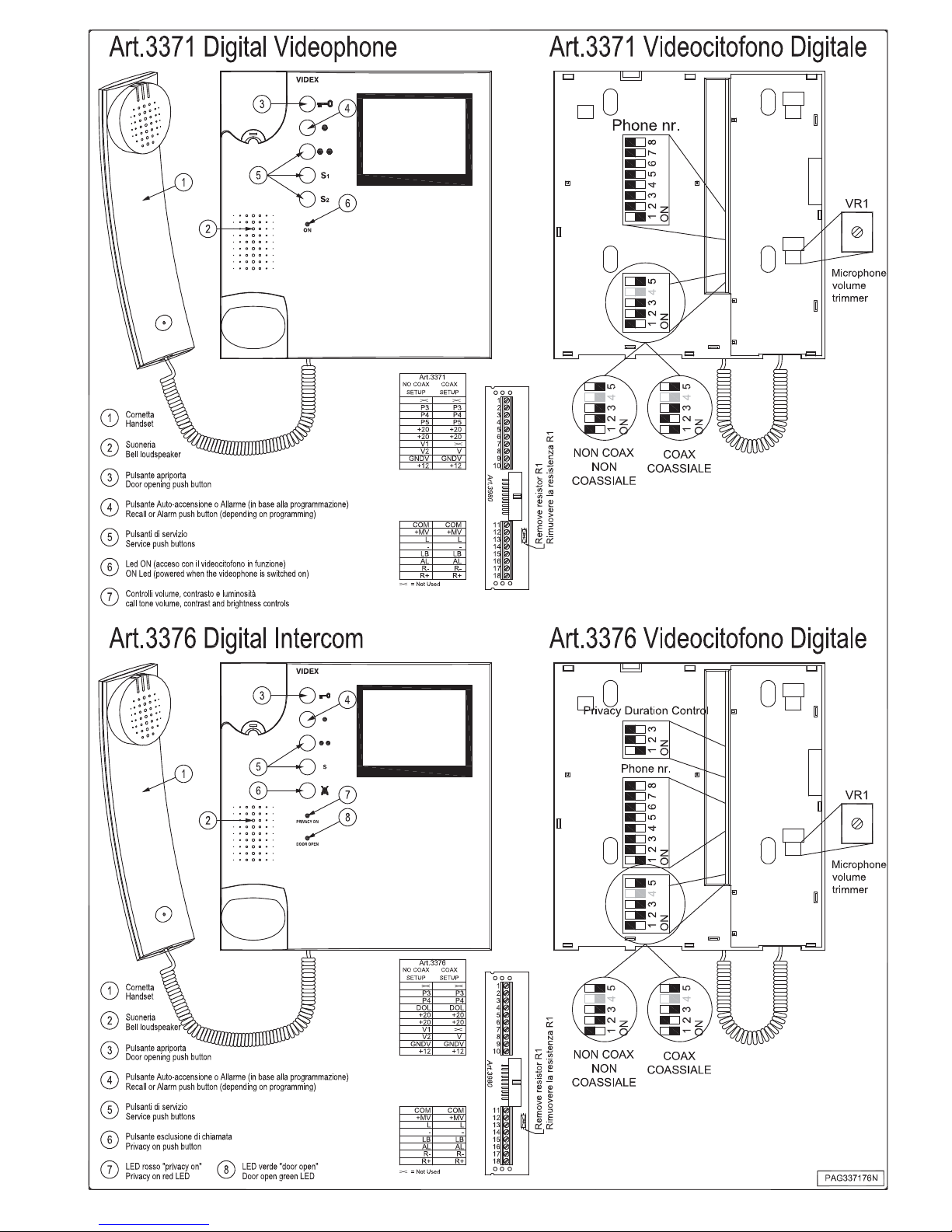
ART.3371 E 3376 VIDEOCITOFONI DIGITALI SERIE
3000 PER SISTEMI VIDEO CON/SENZA COASSIALE
Descrizione
L’Art.3371, basato sul sistema videocitofonico BUS "6 fili", è un videocitofono digitale con 5 pulsanti di cui: uno apri-porta, uno di auto-accensione o
allarme (in base alla configurazione) più 3 pulsanti di servizio. La chiamata,
distinta tra locale e principale, è con nota elettronica e l’utente può regolarne
il volume su 3 livelli. Per la connessione del videocitofono al bus viene impiegata la scheda fornita a corredo della piastra di fissaggio Art.3980. Il videocitofono è dotato di un dip-switch ad 8 vie per la programmazione del suo
indirizzo fisico, di uno a 4 vie per l’impostazione del sistema video (coassiale
o non coassiale) e di un trimmer VR1 per la regolazione del volume microfono (è possibile accedere ad i vari controlli nella parte posteriore del videocitofono). È possibile collegare nello stesso impianto fino a 180 videocitofoni
della serie 3000 ed è consentito (per tutte quelle applicazioni in cui occorre
avere più unità in un unico ambiente) assegnare lo stesso indirizzo ad un
massimo di 3 di essi (in tal caso è necessario alimentare uno dei 3 videocitofoni localmente). Il pulsante apri-porta dell’Art.3371 è anche pulsante di
chiamata verso il centralino (se presente nell’impianto), il pulsante “n” può
essere programmato come pulsante di “auto-accensione” (impostazione standard) o di allarme (da utilizzare in presenza di un centralino di portineria o di
un Art.512DR configurato come scheda relè di servizio) ed i 3 pulsanti di
servizio chiudono tutti verso un contatto comune (morsetto 11 della scheda di
connessione, segnale “COM”). L’Art.3376 è simile all’Art.3371 con un pulsante di servizio in meno e delle funzioni addizionali:
- l’esclusione di chiamata, per l’attivazione del modo “privacy”, che avviene
premendo il pulsante
. L’esclusione termina allo scadere del tempo impostato tramite il relativo dip-switch a 3 vie o premendo nuovamente il pulsante di attivazione. Il led rosso “privacy on” segnala lo stato del servizio
(led acceso: il modo privacy è attivo e le chiamate non vengono ricevute);
- la segnalazione dello stato della porta d’ingresso data dal led “door open”
(led acceso, porta aperta – per l’utilizzo di questo servizio è necessario portare fino al videocitofono un conduttore addizionale proveniente dalla porta
d’ingresso).
Entrambi i modelli di videocitofono consentono il collegamento della scheda
relè Art.402 (opzionale) per l’attivazione di una suoneria esterna al posto di
quella interna.
Funzionamento
In posizione di riposo:
L'unità è pronta ad accettare tutte le chiamate in arrivo;
Per rispondere ad una chiamata ed aprire la porta:
Sollevare la cornetta e parlare con il visitatore (o il centralino); premere il
pulsante "Chiave" (nel caso di chiamata da esterno) per aprire la porta op-
pure chiudere la conversazione riagganciando la cornetta; una eventuale
chiamata proveniente dal campanello locale si può distinguere dalla tonalità
che è diversa da quella della chiamata principale.
Per chiamare il Centralino (solo con centralino versione VX2210-1):
Con la cornetta agganciata premere il pulsante chiave ed attendere: la chiamata viene prenotata sul centralino e servita a discrezione dell’operatore;
Per attivare i servizi legati ai pulsanti ●●, S
1
ed S2:
Premere il pulsante “●●”, “S
1
” o “S2” in base al servizio che si desidera atti-
vare (eseguire gli opportuni collegamenti per l’utilizzo dei servizi).
Per eseguire l’auto-accensione dell’impianto:
Sollevare la cornetta e premere il pulsante “●”, in rapida successione, tante
volte quanto è il valore dell'identificativo (1..10) del posto esterno da accendere (se il posto esterno ha ID=3 premere 3 volte) e dopo circa 1s sarà attivo
il collegamento audio/video con il posto esterno selezionato. Ciascuna pressione del pulsante “●” è confermata da un segnale acustico. Per utilizzare
questa funzione è necessario che il pulsante “●” sia opportunamente programmato e che il centralino di portineria, se presente nel sistema, sia in modo off. Nel caso di sistemi su più livelli, l'auto-accensione opera sugli ingressi
principali.
Per attivare la segnalazione di allarme verso il centralino:
Premere il pulsante “●”. Questa funzione non può essere utilizzata se il relativo pulsante è configurato come pulsante di auto-accensione.
ART.3371 AND 3376 DIGITAL VIDEOPHONES 3000
SERIES FOR COAX/NON COAX VIDEO SYSTEMS
Description
The Art.3371 is a digital videointercom based on a “6 Wire BUS”, it includes 5 push buttons; a door-open button, an alarm or recall (depending on
the settings) button and three general purpose service push buttons. The call
is an electronic tone with a 3 level volume control which can be adjusted by
the user. The local call has a different tonality from the main call. To connect
the videophone to the “BUS”, use the PCB connector provided with the
mounting plate Art.3980. The videophone has an 8 way dip-switch to set the
PHONE ID, a 4 way dip-switch to set the video system (coax or non coax)
and a trimmer (VR1) to adjust the microphone volume; all accessible from
the rear side of the videophone. With the 3000 series it is possible to connect
180 videointercoms on the same system and if necessary it is possible to give
the same address to a max. of 3 of them (for all those applications that require more units for the same apartment, it is also necessary in this case to
power locally one videophone). The door-open push button on the Art.3371 is
also the “call to concierge” (if there is one installed on the system), the
“n” push button can operate as a camera recall button (default setting) or
as an alarm button (for use with the concierge or with an Art.512DR configured as a generic service relay board) and the three service push buttons
close to a common contact (terminal 11 of the PC connection -“COM”)
The Art.3376 has one service button less than the Art.3371 but has some
additional functions:
- the “privacy mode” which is activated by pressing the
push button, it is
signalled by the red led “privacy on” and its duration (except when the
push button is pressed again) depends on the 3 way dip-switch (accessible
from the rear side of the videointercom) settings.
- the visual indication of whether the door is open or closed given by the
green LED “door open”: to use this service, an additional wire is required
from a door contact to the intercom.
Both models of videointercoms allow the connection of an optional relay
board Art.402, for the activation of an external sounder instead of the internal one.
Operation
In stand-by mode:
The unit is ready to accept all incoming calls;
To answer a call and open the door:
Pick the handset up and speak with the visitor (or concierge); press “Key”
button (if it is an external call) to open the door (an acoustic signal will be
emitted and the door will be opened for the time programmed) or replace the
handset to end the conversation; if the call is local (local bell), the call tone
will have a different tonality from the main one.
To call the Concierge Unit (if present and only VX2210-1 version):
With the handset replaced, press the “Key” button and wait: the call is
booked on the concierge and will be answered at the discretion of the operator;
To activate the services relevant to ●●, S
1
& S2 push buttons:
Press the “●●”, “S
1
” or “S2” push button depending on the service you need
to be activated (for the use of these services it is necessary to make the appropriate connections).
To operate the recall:
Pick up the handset then quickly press the “●” push button as many times as
the ID value (1..10) of the outdoor station to switch on (for example if the
ID=3 press the button 3 times). After about 1s the videophone will be connected to the selected outdoor station. An acoustic tone confirms each time
the “●” button is pressed. This function can be used only if the push button is
configured as a recall button; the concierge, if present, must be in OFF
mode. In case of multilevel systems, the recall facility will work with the outdoor station of the main level.
To send the alarm signal to the concierge:
Press the “●” push button. This function can be used only if this push button
isn’t configured as a recall one.
Page 3

VIDEX ELECTRONICS S.p.A. VX2200 “2 WIRE” Bus Digital System
62
Per attivare l’esclusione di chiamata (solo Art.3376):
Premere il pulsante contrassegnato dal simbolo
: il led rosso “privacy on” si
accenderà. Per disattivare il servizio prima dello scadere dell’intervallo di
tempo impostato, premere nuovamente lo stesso pulsante.
Per selezionare la suoneria desiderata:
1. Tenere premuto il tasto “chiave” fino a che (dopo circa 10 secondi) il
citofono non riproduce la suoneria attiva; al termine della riproduzione
il citofono emette un bip (fine riproduzione);
2. Ascoltare le suonerie disponibili premendo e rilasciando il tasto “chia-
ve” dopo ogni bip di fine riproduzione;
3. Trascorsi circa 3 secondi dopo il bip di fine riproduzione senza premere
il tasto “chiave”, viene selezionata l’ultima suoneria riprodotta.
La suoneria selezionata sarà riprodotta tante volte quant’è il valore impostato
per il numero di squilli (vedi programmazione squilli).
Programmazione
La programmazione di questi videocitofoni consiste nelle seguenti impostazioni:
- Configurazione dell’indirizzo fisico del videocitofono che viene effettuata
agendo sul dip-switch ad 8 vie. Fare riferimento alla tabella di conversione
decimale/binario di pagina 68.
- Configurazione del sistema video: coassiale o bilanciato (non coassiale).
Fare riferimento alle possibili impostazioni del dip-switch a 5 nella tabella
che segue questo testo.
- Configurazione del numero di squilli; l’impostazione di default è 3 per
passare a 6 procedere nel seguente modo:
a. togliere l’alimentazione al videocitofono staccandone il flat dalla
scheda di connessione;
b. mettere in corto i morsetti 14 e 15 (segnali “-” ed LB) della scheda di
connessione;
c. ricollegare il flat del videocitofono alla scheda di connessione ed at-
tendere un doppio bip prima di rimuovere il corto dai morsetti 14 e
15;
d. per tornare a 3 squilli procedere alla stessa maniera ripartendo dal
punto (a), ma al punto (c) attendere un solo bip prima di rimuovere il
corto tra i due morsetti.
- Configurazione del pulsante “n”; la funzione impostata di default per que-
sto pulsante è quella di autoaccensione, per configurarlo come tasto di allarme procedere nel seguente modo:
a. togliere l’alimentazione al videocitofono staccandone il flat dalla
scheda di connessione;
b. ricollegare il flat tenendo premuto il pulsante “n” e rilasciarlo dopo
aver udito 2 bip;
c. per ritornare alla funzione di “auto-accensione”, ripartire dal punto
(a), ma al punto (b) attendere un solo bip prima di rilasciare il pulsan-
te “n”.
Per utilizzare l’Art.402 con il 3371 o il 3376, portare lo switch 4 del dipswitch a 5 vie (normalmente su ON) in posizione OFF.
L’Art.402 è fornito con 2 fili di collegamento verso la scheda di connessione:
il nero va al morsetto 17 (segnale R-) ed il rosso al morsetto 18 (segnale R+).
Per l’Art.3376 occorre programmare la durata dell’esclusione di chiamata,
agendo sul Dip-Switch a 3 vie (accessibile nella parte posteriore del videocitofono) come indicato dalla tabella seguente.
To activate the privacy mode (only Art.3376)
Press the push button marked as
: the red LED “privacy on” will be
switched on. To disable the privacy mode before the configured time expires,
press the same push button again.
To select the desired melody:
1. Keep pressed the “key” button until (after about 10 seconds) the inter-
com play the active melody; at the end of melody play, the intercom
emit a beep (end of play);
2. Listen the available melodies operating (press and release) the “key”
button after the beep at the end of play;
3. After the end of play beep if you don’t press the “key” button within 3
seconds, the last melody heard is selected.
The selected melody will play how many times how is the number of rings
value (3 or 6) programmed.
Programming
The programming of this videophone consists of different phases:
- Setting of the PHONE ID made by setting internal 8 way dip-switch shown
on decimal/binary conversion table on page 68 of this manual;
- Setting of the video system: coax or balanced (non coax). Refer to the 5 way
dip-switch settings shown on the table that follows.
- Setting of the number of rings; the default setting is 3 to set 6 rings operate
as follows:
a. switch off the videophone by unplugging the flat cable from the PCB
connection;
b. make a short between terminals 14 and 15 (signals “-” and “LB”) of
the PCB connection;
c. plug the flat cable onto the PCB connection and wait for a double
beep before removing the short between terminals 14 and 15;
d. to go back to 3 rings, do the same but wait for only one beep before
removing the short between terminals 14 and 15.
- Setting of the “n” push button function; the default function setting for
this push button is the recall one, to set the push button as an alarm one
operate as follows:
a. switch off the videophone by unplugging the flat cable from the PCB
connection;
b. while pressing the “n” push button, plug the flat cable onto the PCB
connection and wait for a double beep before release the push button;
c. to go back to recall function, do the same but wait for only one beep
before release the push button.
When you use the Art.402 for both Art.3371 and 3376, the fourth switch on
the 5 way dip-switch should be moved to OFF.
The wires of the Art.402 must be connected as black to terminal 17 (R- signal) and the red to terminal 18 (R+ signal) of the PCB connection.
For the Art.3376 it is necessary to set the duration of the privacy mode by
setting the 3 way dip-switch (accessible from the rear side of the videophone) as shown on the table below.
Dip-Switch
1 2 3
Time/Tempo
off off off unlimited / illimitato
on off off 15min
off on off 30min
on on off 1 hour / ora
off off on 2 hours / ore
on off on 4 hours / ore
off on on 8 hours / ore
on on on 16 hours / ore
Video Mode Setup 5 way dip-switch / Modo Video dip-switch a 5 vie
video mode / modo video
Dip-switch
Coax video mode / Modo video coassiale
Balanced (non coax) / Modo video bilanciato
Note
Dovendo collegare in parallelo il segnale video di più videocitofoni (max 3,
3371 o 3376), configurati per il sistema coassiale o bilanciato, impostare gli
switch 3 e 5 in posizione OFF per tutti i videocitofoni ad eccezione
dell’ultimo in ordine di collegamento.
Notes
When you have more videophones set for coax or balanced video system with
the video cables in a parallel connection (max 3 3371 or 3376), for each one
except the last (normally the furthest connected) set the switches 3 and 5 =
OFF.
Page 4

63
Art.3371 - Descrizione dei segnali presenti sui morsetti dell’Art.3980 Art.3371 - Description of the signals on the Art.3980’s terminals
Impostazione non coassiale Impostazione coassiale
Set as no coax Set as coax
Non usato
1
Not used
P3 - Pulsante chiusura contatto verso COM
2
P3 - Push button link to COM terminal
P4 - Pulsante chiusura contatto verso COM
3
P4 - Push button link to COM terminal
P5 - Pulsante chiusura contatto verso COM
4
P5 - Push button link to COM terminal
+20 - Ingresso alimentazione +20Vdc per alimentazione monitor
5
+20 - +20Vdc monitor power supply
+20 - Ingresso alimentazione +20Vdc per alimentazione monitor
6
+20 - +20Vdc monitor power supply
V1 (segnale video bil. sync-)
Non usato 7
V1 (balanced video signal sync-)
Not used
V2 (segnale video bil. sync+) V - Segnale video
8
V2 (balanced video signal sync+) V - Video Signal
GNDV - Riferimento di massa per il segnale video
9
GNDV Ground reference for video signal
+12 - Uscita 12Vdc per alimentazione del distributore video (Art.894)1
10
+12 - 12Vdc output for coax video distributor Art.894 power supply1
COM - Comune pulsanti P3, P4 e P5
11
COM - Common terminal for P3, P4 and P5
+MV - Ingresso +12Vdc per alimentazione memoria video2
12
+MV - Ingresso +12Vdc oer alimentazione memoria video2
13
L, − - Linea BUS
14
L, − - Linea BUS
LB - Ingresso per campanello locale (senale di massa)
15
LB - Local bell inpu (groud signal)
AL - Ingresso per segnale di allarme (segnale di massa)
16
AL - Alarm signal input (ground signal)
17
R-,R+ - morsetti per il collegamento della scheda relay Art.402 (filo
nero al morsetto R- e filo rosso al morsetto R+)
18
R-,R+ - Connection terminal for the additional relay board Art.402
(black wire to terminal R-, red wire to terminal R+)
Note
1
La tensione è disponibile solo a monitor acceso e viene di norma utilizzata
solo nei sistemi coassiali.
2
Utilizzato solo nei modelli con memoria video Art.35xx.
Notes
1
The voltage is available when the monitor is switched on but it is normally
used on coax systems only.
2
Only for monitor with memory board Art.35xx.
Art.3376 - Descrizione dei segnali presenti sui morsetti dell’Art.3980 Art.3376 - Description of the signals on the Art.3980’s terminals
Impostazione non coassiale Impostazione coassiale
Set as no coax Set as coax
Non usato
1
Not used
P3 - Pulsante chiusura contatto verso COM
2
P3 - Push button link to COM terminal
P4 - Pulsante chiusura contatto verso COM
3
P4 - Push button link to COM terminal
DOL - Ingresso segnale “DOOR OPEN LED” (+12Vdc 5mA)
4
DOL - Door open LED signal (+12Vdc 5mA signal)
+20 - Ingresso alimentazione +20Vdc per alimentazione monitor
5
+20 - +20Vdc monitor power supply
+20 - Ingresso alimentazione +20Vdc per alimentazione monitor
6
+20 - +20Vdc monitor power supply
V1 (segnale video bil. sync-)
Non usato 7
V1 (balanced video signal sync-)
Not used
V2 (segnale video bil. sync+) V - Segnale video
8
V2 (balanced video signal sync+) V - Video Signal
GNDV - Riferimento di massa per il segnale video
9
GNDV Ground reference for video signal
+12 - Uscita 12Vdc per alimentazione del distributore video (Art.894)1
10
+12 - 12Vdc output for coax video distributor Art.894 power supply1
COM - Comune pulsanti P3, P4 e P5
11
COM - Common terminal for P3, P4 and P5
+MV - Ingresso +12Vdc per alimentazione memoria video2
12
+MV - Ingresso +12Vdc oer alimentazione memoria video2
13
L, − - Linea BUS
14
L, − - Linea BUS
LB - Ingresso per campanello locale (senale di massa)
15
LB - Local bell inpu (groud signal)
AL - Ingresso per segnale di allarme (segnale di massa)
16
AL - Alarm signal input (ground signal)
17
R-,R+ - morsetti per il collegamento della scheda relay Art.402 (filo
nero al morsetto R- e filo rosso al morsetto R+)
18
R-,R+ - Connection terminal for the additional relay board Art.402
(black wire to terminal R-, red wire to terminal R+)
Note
1
La tensione è disponibile solo a monitor acceso e viene di norma utilizzata
solo nei sistemi coassiali.
2
Utilizzato solo nei modelli con memoria video Art.35xx.
Notes
1
The voltage is available when the monitor is switched on but it is normally
used on coax systems only.
2
Only for monitor with memory board Art.35xx.
Specifiche Tecniche
Gamma di indirizzamento : da 1 a 180 (codice BIN)
Assorbimento in posizione riposo : 0,6 mA circa
Assorbimento massimo : 400 mA circa (20 Volt)
Temperatura : -10 +50 Cº
Technical Specifications
Addressing range : from 1 to 180 (BIN code)
Stand-by absorption : about 0,6 mA
Videophone max. absorption : about 400mA (20 Volt)
Working temperature : -10 +50 C°
 Loading...