

Page 1
PrtCode:66250140.doc 06/10/2005 Rev.1.0
3313
Videophone with electronic privacy
Art.
3413
Videocitofono con privacy elettronica
INSTALLATION INSTRUCTION
ISTRUZIONI D’INSTALLAZIONE
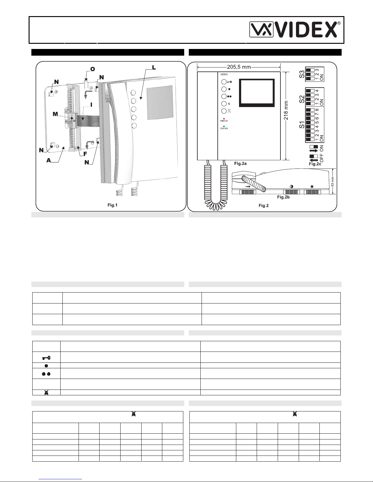
INSTALLING THE VIDEOPHONE ONTO MOUNTING PLATE APPLICAZIONE VIDEOCITOFONO ALLA PIASTRA DI FISSAGGIO
As shown in fig.1, move the videophone L close to the mounting plate A
so that the ribbon cable will reach the connector I.
As shown in fig.1, connect the female plug on the ribbon cable I coming
from the videophone to the male plug connector M on the PCB F.
Place the videophone L against the 4 hooks N on the mounting plate A
and push down: the videophone will automatically lock into place using
clasp O as shown in fig.1.
To remove the videophone from the wall, push the clasp O in the
direction of the wall with a screwdriver and at the same time push the
videophone upwards.
Avvicinare, come da fig.1, il videocitofono L alla piastra A per agevolare
la connessione del flat I.
Come mostrato in fig.1 inserire il connettore del flat I, che fuoriesce dalla
parte posteriore del videocitofono, nel connettore M della scheda di
connessione F.
Facendo corrispondere le 4 fessure presenti sulla base del videocitofono
L con i 4 incastri N della piastra A, appoggiare il video sulla piastra e
spingerlo verso il basso fino allo scatto, compiendo un movimento come
mostrato dalle frecce in fig.1.
Per rimuovere il videocitofono, spingere con un cacciavite a taglio il
dente O verso il muro e, contemporaneamente, tirare il videocitofono
verso l’alto.
LEDS LED
COLOR
COLORE
MEANING SIGNIFICATO
Green
Verde
Door Open LED. On until the door is open. Require a +12Vdc
input at the terminal “13” until the door is open.
LED porta aperta. Acceso fino a che la porta resta aperta.
Necessita +12Vdc sul morsetto “13”.
Red
Rosso
Mute LED. On with fixed or flashing light until the mute function is
enabled.
LED mute. Acceso in maniera stabile o lampeggiante fino a che
la funzione mute è attiva.
PUSH BUTTONS OPERATION FUNZIONAMENTO PULSANTI
BUTTON
Pulsante
FUNCTION
FUNZIONE
Activates the electric lock (door-open) only when the videophone
is on and the handset is picked up.
Attiva la serratura elettrica (apri-porta) quando il videocitofono è
acceso e la cornetta è sollevata.
Camera recall. Auto-accensione.
Camera recall or link between terminals “3” and “16”. (see 12 way
deep switch settings).
Auto-accensione o collegamento tra i morsetti “3” e “16” (vedi
configurazione dip-switch a 12 vie).
s
Camera recall or link between terminals “17” and “16”. (see 12
way deep switch settings)
Auto-accensione o collegamento tra i morsetti “17” e “16” (vedi
configurazione dip-switch a 12 vie).
Mute switch. Enable or disable the mute function. Interruttore mute. Abilita/Disabilita la funzione ad ogni pressione.
8 WAY DIP SWITCH SETTINGS (S1 FIG.2C)
MUTE DURATION TIME
(switches 1 to 5)
Switches
Time (hours)
1 2 3 4 5
¼ ON OFF OFF OFF OFF
½ OFF ON OFF OFF OFF
2 OFF OFF ON OFF OFF
4 OFF OFF OFF ON OFF
8 OFF OFF OFF OFF ON
IMPOSTAZIONE DIP-SWITCH A 8 VIE (S1 FIG.2C)
DURATA FUNZIONE MUTE
(switch da 1 a 5)
Switch/
Durata (ore)
1 2 3 4 5
¼ ON OFF OFF OFF OFF
½ OFF ON OFF OFF OFF
2 OFF OFF ON OFF OFF
4 OFF OFF OFF ON OFF
8 OFF OFF OFF OFF ON
Page 2
PrtCode:66250140.doc 06/10/2005 Rev.1.0
MUTE LED SIGNALLING
(switch 6)
Switches
Signalling
6
Fixed
OFF
Blinking
ON
BUTTON OPERATION
(switches 7, 8)
Switches
Op. Mode
7 8
Camera
Recall
ON OFF
Link 3-16
OFF ON
SEGNALAZIOEN LED MUTE
(switch 6)
Switch/
Segnalazione
6
Fissa
OFF
Lampeggiante
ON
FUNZ. PULSANTE
(switch 7, 8)
Switch
Modalità
7 8
Autoaccensione
ON OFF
Colleg. 3-16
OFF ON
4 WAY DIP SWITCH SETTINGS (S2 FIG.2C) IMPOSTAZIONE DIP-SWITCH A 4 VIE (S2 FIG.2C)
S BUTTON OPERATION
(switches 1, 2)
Switches
Op. Mode
1 2
Camera
Recall
ON OFF
Link 17-16
OFF ON
VIDEO MODE
(switches 3, 4)
Switches
Op.Mode
3 4
Coax
ON ON
No Coax
OFF OFF
FUNZ. PULSANTE S
(switch 1, 2)
Switch/
Modalità
1 2
Autoaccensione
ON OFF
Colleg. 17-16
OFF ON
MODO VIDEO
(switches 3, 4)
Switch/
Modalità
3 4
Coassiale
ON ON
Non coassiale
OFF OFF
3 WAY DIP-SWITCH SETTINGS (S3 FIG.2C) IMPOSTAZIONE DIP-SWITCH A 3 VIE (S3 FIG.2C)
VIDEO MODE COAX/NO COAX
(switches 1 to 3)
Switches/
Video Mode
1 2 3
Coax
OFF OFF OFF
No Coax
ON ON ON
MODO VIDEO COASSIALE/NON COASSIATE
(switch da 1 a 3)
Switch/
Modo Video
1 2 3
Coassiale
OFF OFF OFF
Non coassiale
ON ON ON
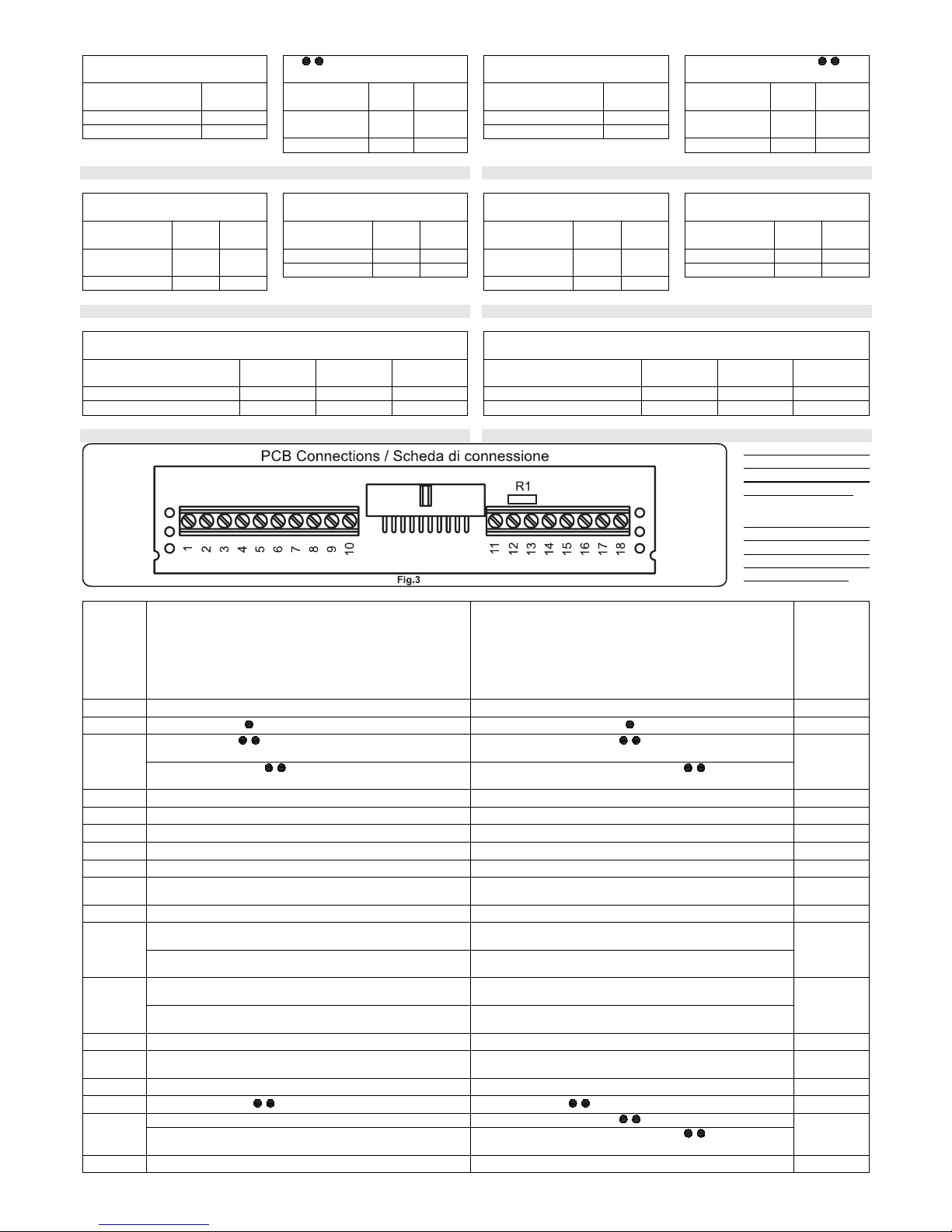
TERMINALS – SIGNALS MORSETTI – SEGNALI
Note: if the videophone
is set for non coax
video system, remove
the resistor R1 (fig.3)
Nota: quando il video
citofono è impostato per
il sistema video non
coassiale, rimuovere la
resistenza R1 (fig.3)
Art.3980
TERMINALS
MORSETTI
SIGNAL
DESCRIPTION
DESCRIZIONE
SEGNALE
Signal
Direction
Direzione
Segnale
1
+12 Vdc output. Normally used to supply a video distributor Uscita +12Vdc. Per alimentazione distributore video Output
2
Camera Recall ( push button) Auto-accensione (pulsante ) Output
Camera Recall ( push button) S1 SW7=ON SW8=OFF Auto-accensione (pulsante ) S1 SW7=ON SW8=OFF
3
Link to terminal “16” ( push button) S1 SW7=OFF
SW8=ON
Chiusura verso morsetto “16” (pulsante ) S1 SW7=OFF
SW8=ON
Output
4
+20Vdc power input Ingresso alimentazione +20Vdc Input
5
Door open command Comando apri-porta Output
6
Speech out Uscita fonia Output
7
Speech in Ingresso fonia Input
8
Ground (speech and power supply) Massa (alimentazione e fonia) Input
9
Normally unused. To connect to ground to disable privacy
of speech
Normalmente non utilizzato. Va collegato a massa per
disattivare il segreto di conversazione
Input
10
Electronic call tone input (local call) Ingresso per chiamata con nota elettronica (locale) Input
Balanced video signal synch- with the videophone set for
non coax system (see S1, S2 settings)
Segnale video bilanciato synch- - videocitofono impostato
per il sistema video non coassiale (vedi dip-switch)
11
Video signal with the videophone set for coax video system
(see S1, S2 settings)
Segnale video - videocitofono impostato per il sistema
video coassiale (vedi dip-switch)
Input
Balanced video signal synch+ with the videophone set for
non coax system (see S1, S2 settings)
Segnale video bilanciato synch+ - videocitofono impostato
per il sistema video non coassiale (vedi dip-switch)
12
Video signal ground with the videophone set for coax video
system (see S1, S2 settings)
Massa segnale video - videocitofono impostato per il
sistema video coassiale (vedi dip-switch)
Input
13
+12Vdc “door open” LED (green) power supply. Alimentazione +12Vdc per LED (verde) “porta aperta” Input
14
Videophone enable command input. Enabled by a call
tone.
Ingresso d’abilitazione videocitofono. Abilitazione tramite
nota di chiamata.
Input
15
Call tone input (main call) Ingresso tono di chiamata (principale) Input
16
Common terminal ( , S push button) Comune pulsanti , S
Input
Camera Recall (S push button) S1 SW9=ON SW10=OFF
Auto-accensione (pulsante
) S1 SW9=ON SW10=OFF
17
Link to terminal “16” (S push button) S1 SW9=OFF
SW10=ON
Chiusura verso morsetto “16” (pulsante
) S1 SW9=OFF
SW10=ON
Output
18
+12Vdc power input to supply the mute timer. Alimentazione +12Vdc per timer mute Input
Page 3

PrtCode:66250140.doc 06/10/2005 Rev.1.0
TECHNICAL SPECIFICATION SPECIFICHE TECNICHE
Working Voltage: 20Vdc
Stand-by absorption: 0mA
Max absorption: 400mA (3313) – 500mA (3413)
Working temperature -10+50 Cº
Tensione d’alimentazione: 20Vdc
Assorbimento a riposo: 0mA
Assorbimento massimo: 400mA (3313) – 500mA (3413)
Temperatura di lavoro: -10 +50 Cº
INSTALLATION DIAGRAM SCHEMA D’INSTALLAZIONE
Page 4

PrtCode:66250140.doc 06/10/2005 Rev.1.0
CUSTOMER SUPPORT INFORMATION INFORMAZIONI ASSISTENZA CLIENTI
All Countries Customers UK Customers Clienti di tutti i Paesi Clienti UK
VIDEX Electronics S.p.A.
www.videx.it
– technical@videx.it
Tel.+39 0734 631669
Fax +39 0734 632475
VIDEX Security LTD
www.videx-security.com
Tech Line 0191 224 3174
Fax 0191 224 1559
VIDEX Electronics S.p.A.
www.videx.it – technical@videx.it
Tel.+39 0734 631669
Fax +39 0734 632475
VIDEX Security LTD
www.videx-security.com
Tech Line 0191 224 3174
Fax 0191 224 1559
The product is CE marked d emonstrating its c onformity and is for distribution withi n all
member states of the EU wi th no restrictions.
This product follows the provisions of the European Directives
89/336/EEC & 92/31/EEC (EMC),
73/23/EEC (LVD) and 93/68/EEC (CE marking).
Il prodotto è marchi ato CE a dimos trazione del la sua conform ità e può es sere distri buito
liberamente all’inter no dei paesi membri dell’unione europea EU.
Questo prodotto è conforme alle direttive Europee
89/336/EEC & 92/31/EEC (EMC),
73/23/EEC (LVD) e 93/68/EEC (Marcatura CE).
 Loading...