

Page 1
PrtCode:66250390.doc 03/12/2007 Rev.1.5 Pag.1/8
Coax / non-coax videophone
Art.33,34,3512
Videocitofono coax / no coax
INSTALLATION INSTRUCTION
ISTRUZIONI D’INSTALLAZIONE
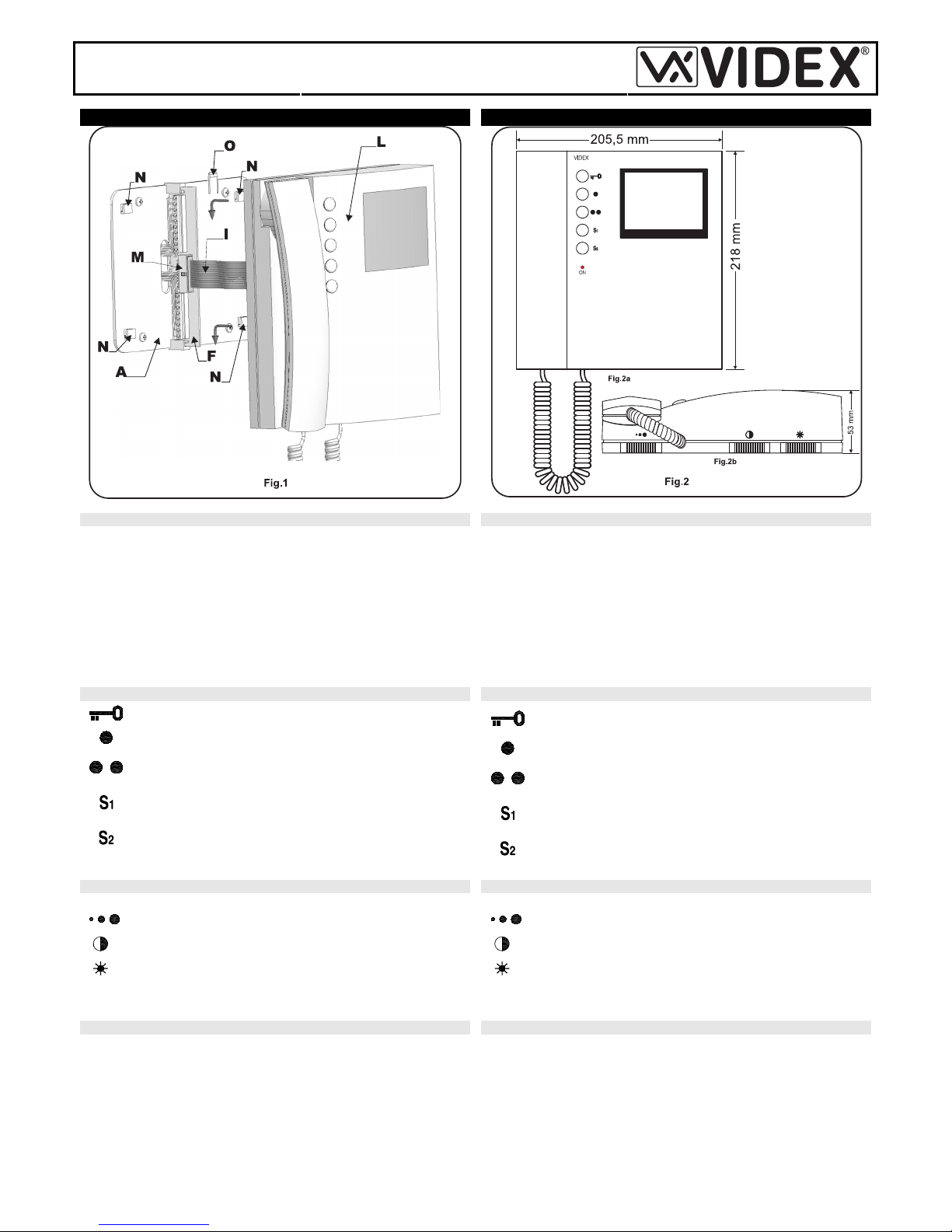
INSTALLING THE VIDEOPHONE ONTO THE MOUNTING PLATE APPLICAZIONE VIDEOCITOFONO ALLA PIASTRA DI FISSAGGIO
• As shown in fig.1, move the videophone L close to the mounting plate A
so that the ribbon cable will reach the connector I.
• As shown in fig.1, connect the female plug on the ribbon cable I coming
from the videophone to the male plug connector M on the PCB F.
• Place the videophone L against the 4 hooks N on the mounting plate A
and push down: the videophone will automatically lock into place using
clasp O as shown in fig.1.
• To remove the videophone from the wall, push the clasp O in the direc-
tion of the wall with a screwdriver and at the same time push the videophone upwards.
• Avvicinare, come da fig.1, il videocitofono L alla piastra A per agevolare
la connessione del flat I.
• Come mostrato in fig.1, inserire il connettore del flat I, che fuoriesce dalla parte posteriore del videocitofono, nel connettore M della scheda di
connessione F.
• Facendo corrispondere le 4 fessure presenti sulla base del videocitofono
L con i 4 incastri N della piastra A, appoggiare il video sulla piastra e
spingerlo verso il basso fino allo scatto, compiendo un movimento come
mostrato dalle frecce in fig.1.
• Per rimuovere il videocitofono, spingere con un cacciavite a taglio il dente O verso il muro tirando il videocitofono verso l’alto.
PUSH BUTTONS (fig.2a) PULSANTI (fig.2a)
Door opening button (only with video on and handset lifted)
Camera recall button
Dry contact between terminal (3) and terminal (16) or camera
recall function (see the table 1)
Dry contact between terminal (17) and terminal (16) or camera recall function (see the table 1)
Dry contact between terminal (18) and terminal (16) or camera recall function (see the table 1)
Attiva la serratura elettrica con video acceso e cornetta sollevata
Attiva l’impianto dall’interno (auto-accensione)
Chiude il relativo morsetto (3) verso il morsetto comune (16)
o ha funzione di auto-accensione (vedi tabella 1)
Chiude il relativo morsetto (17) verso il morsetto comune (16)
o ha funzione di auto-accensione (vedi tabella 1)
Chiude il relativo morsetto (18) verso il morsetto comune (16)
o ha funzione di auto-accensione (vedi tabella 1)
ADJUSTMENTS (fig.2b) REGOLAZIONI (fig.2b)
Operation of the controls at the bottom of the videophone Fig.2b.
Adjust the call tone volume (for both local and external call)
Adjust the monitor contast
Adjust the monitor brightness
Move slide control right to increase or left to decrease.
Per le regolazioni agire sui controlli alla base del videocitofono Fig.2b.
Regola il volume del tono di chiamata (sia esterna che locale)
Regola il contrasto del monitor
Regola la luminosità del monitor
Muovere il controllo a slitta a destra per incrementare o a sinistra per decrementare.
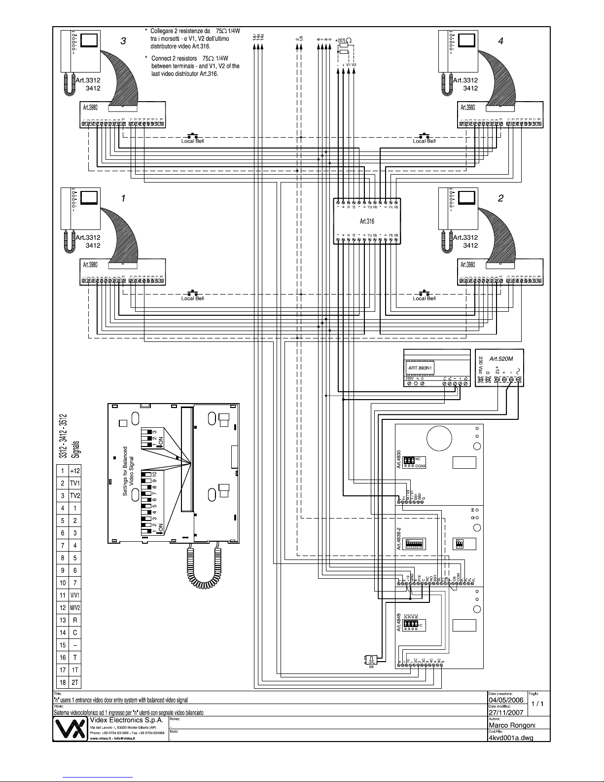
900 SERIES COMPATIBILITY COMPATIBILITÀ CON LA SERIE 900
The 3000 series videophones are compatible with the 900 series videophones and can be installed on the same system*. The only difference
between the 3000 and 900 series is that the 3000 series "main calls " and
"local calls " are both electronic call as oppose to one being an AC buzzer.
The table 2 shows the conversion between 900 and 3000 series connections (I.E. "TV2" signal will be on terminal "3" for videophone models
33/34/3512).
I videocitofoni della serie 3000 sono compatibili con la serie 900 e possono essere installati nello stesso impianto*; l’unica differenza sta nel fatto
che per i modelli della serie 3000 la “chiamata esterna” e la “chiamata di
piano” (o “locale”) sono entrambe con nota elettronica. La tabella 2 (segnali) mostra la corrispondenza tra i morsetti della scheda di connessione
dell’Art.3980 ed i segnali con la denominazione utilizzata per la serie 900
(ad esempio il segnale TV2 va collegato al morsetto “3” della scheda di
connessione per i videocitofoni modello 33/34/3512).
*Only when videophones model 33/34/3512 are used as coax videophones
*Solo quando i videocitofoni modello 33/34/3512 sono utilizzati come coassiali.
Page 2
PrtCode:66250390.doc 03/12/2007 Rev.1.5 Pag.2/8
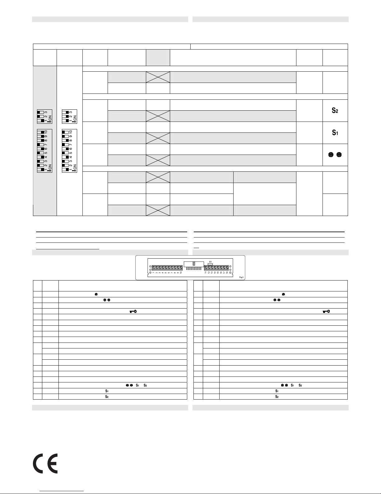
SETTINGS IMPOSTAZIONE
The video system in use, the answer mode and the operation of the service buttons are configured through the 10 way and 3 way dip-switches on
the back of the videophone inside the hole for connection board housing.
Il tipo di sistema video, la modalità di risposta alle chiamate e le funzioni
dei tasti di servizio sono impostate tramite i dip switch a 10 e 3 vie accessibili nella parte posteriore del videocitofono all’interno dell’incavo di alloggiamento della scheda di connessione.
Answer mode, service button operation and video mode Modo di risposta, funzione tasti di servizio e modo video
Coax
Default
Settings
Balanced
Default
Settings
Switches
Switch
Status
Stato
Factory
Default
Settings
Function
Funzione
Terminal
Morsetto
Button
Pulsante
Answer Mode Setup – Configurazione Modo Risposta
ON, OFF
Incoming call switches on the monitor
La chiamata accende il monitor del videocitofono
1,2
OFF, OFF
Incoming call does not switch on the monitor
La chiamata non accende il monitor del videocitofono
Service Push Buttons Operating Mode Setup – Configurazione Funzionamento Pulsanti di Servizio
ON, OFF
Recall command
Auto-accensione
3,4
OFF, ON
Dry contact between terminal 18 & 16
Collegamento interno con il morsetto comune 16
18
ON, OFF
Recall command
Auto-accensione
5,6
OFF, ON
Dry contact between terminal 17 & 16
Collegamento interno con il morsetto comune 16
17
ON, OFF
Recall command
Auto-accensione
7,8
OFF, ON
Dry contact between terminal 3 & 16
Collegamento interno con il morsetto comune 16
3
Video Mode Setup – Configurazione Modo Video
ON, ON
Coax video signal
Segnale video coassiale
11 = V
12 = M
9,10
OFF, OFF
Balanced video signal
Segnale video bilanciato
ON, ON, ON
Balanced video signal
Segnale video bilanciato
11 = V1, 12 = V2
*
1,2,3
ON, OFF, OFF
Coax video signal
Segnale video coassiale
11 = V
12 = M
11,12
Table 1 / Tabella 1
Notes Note
In case of more videophones in a parallel connection in a coax video
door entry system, put (only for videophones in parallel) the switch 1 of
the 3 way dip switch to OFF for all videophone except for the last in con-
nection order (i.e. End of line).
In caso di più videocitofoni in parallelo in un sistema video coassiale,
impostare, solo per quelli in parallelo, lo switch 1 del dip-switch a 3 vie in
posizione OFF per tutti ad eccezione dell’ultimo in ordine di collegamento.
SIGNALS ON PCB CONNECTION BOARD SEGNALI SCHEDA DI CONNESSIONE
* Remove the resistor
R1 if fitted.
* Rimuovere la resistenza R1 se presente.
1 +12V
+12V output to supply the video distributor (Art.894) / +12V
input to supply memory board (only 3512)
2 TV1
Recall – button
3 TV2
See table 1 – button
4 1
Positive power input +15÷20Vdc 0,75A
5 2
Door opening command – button
6 3
Speech output
7 4
Speech input
8 5
Speech ground
9 6
Negative power input (ground)
10 7
Local call input (electronic call tone)
V
Coax video signal input 0,8-1,5 Vpp (see table 1)
11
V1 Balanced video signal input sync. – (see table 1)
M
Coax video signal ground (see table 1)
12
V2 Balanced video signal sync. + (see table 1)
13 R
Speech common for intercommunicating systems
14 C
External call input (electronic call tone)
15 –
Speech ground for intercommunicating systems
16 T
Service push buttons common (
, , )
17 1T
See table 1 – button
18 2T
See table 1 – button
1 +12V
Uscita +12V per alimentazione distributore video (Art.894) /
ingresso +12V per alimentazione memory board (solo 3512)
2 TV1 Auto-accensione – pulsante
3 TV2 Vedi tabella 1 – pulsante
4 1 Ingresso positivo alimentazione +15÷20Vdc 0,75A
5 2 Comando per azionamento apri-porta – pulsante
6 3 Uscita fonia
7 4 Ingresso fonia
8 5 Massa fonia
9 6 Ingresso negativo alimentazione (massa)
10 7 Ingresso per chiamata di piano (nota elettronica)
V Ingresso segnale video 0,8-1,5 Vpp (Vedi tabella 1)
11
V1 Ingresso segnale video bilanciato sync. – (Vedi tabella 1)
M Massa segnale video (Vedi tabella 1)
12
V2 Ingresso segnale video bilanciato sync. + (Vedi tabella 1)
13 R Comune fonia intercomunicante
14 C Ingresso per chiamata da esterno (nota elettronica)
15 – Massa fonica per impianti intercomunicanti
16 T Comune pulsanti di servizio ( , , )
17 1T Vedi tabella 1 – pulsante
18 2T Vedi tabella 1 – pulsante
Table 2 / Tabella 2
TECHNICAL SPECIFICATION SPECIFICHE TECNICE
Voltages
Videophone: 20Vdc (+2 -5V)
Memory board (solo 3512): 12Vdc (+1 -4V)
Current consumption Stand-by When operating
Videophone (3312,3512): 0 mA 400mA max
Videophone (3412) 0 mA 500mA max
Memory board (solo 3512): 110 mA 110mA max
Tensioni d’alimentazione
Videocitofono: 20Vdc (+2 -5V)
Memory board (solo 3512): 12Vdc (+1 -4V)
Assorbimento a riposo in funzione
Videocitofono (3312,3512): 0 mA 400mA max
Videocitofono (3412) 0 mA 500mA max
Memory board (solo 3512): 110 mA 110mA max
The product is CE marked demonstrating its conformity and is for distribution within all
member states of the EU with no restrictions.
This product follows the provisions of the European Directives
89/336/EEC & 92/31/EEC (EMC),
73/23/EEC (LVD) and 93/68/EEC (CE marking).
Il prodotto è marchiato CE a dimostrazione della sua conformità e può essere distribuito
liberamente all’interno dei paesi membri dell’unione europ ea EU.
Questo prodotto è conforme alle direttive Europee
89/336/EEC & 92/31/EEC (EMC),
73/23/EEC (LVD) e 93/68/EEC (Marcat ura CE).
*
Page 3
PrtCode:66250390.doc 03/12/2007 Rev.1.5 Pag.3/8
Page 4

PrtCode:66250390.doc 03/12/2007 Rev.1.5 Pag.4/8
Page 5

PrtCode:66250390.doc 03/12/2007 Rev.1.5 Pag.5/8
Page 6

PrtCode:66250390.doc 03/12/2007 Rev.1.5 Pag.6/8
Page 7

PrtCode:66250390.doc 03/12/2007 Rev.1.5 Pag.7/8
Page 8

PrtCode:66250390.doc 03/12/2007 Rev.1.5 Pag.8/8
CUSTOMER SUPPORT INFORMATION INFORMAZIONI ASSISTENZA CLIENTI
All Countries Customers UK Customers Clienti di tutti i Paesi Clienti UK
VIDEX Electronics S.p.A.
www.videx.it
– technical@videx.it
Tel.+39 0734 631669
Fax +39 0734 632475
VIDEX Security LTD
www.videx-security.com
Tech Line 0191 224 3174
Fax 0191 224 1559
VIDEX Electronics S.p.A.
www.videx.it
– technical@videx.it
Tel.+39 0734 631669
Fax +39 0734 632475
VIDEX Security LTD
www.videx-security.com
Tech Line 0191 224 3174
Fax 0191 224 1559
 Loading...