

Page 1
VIDEX
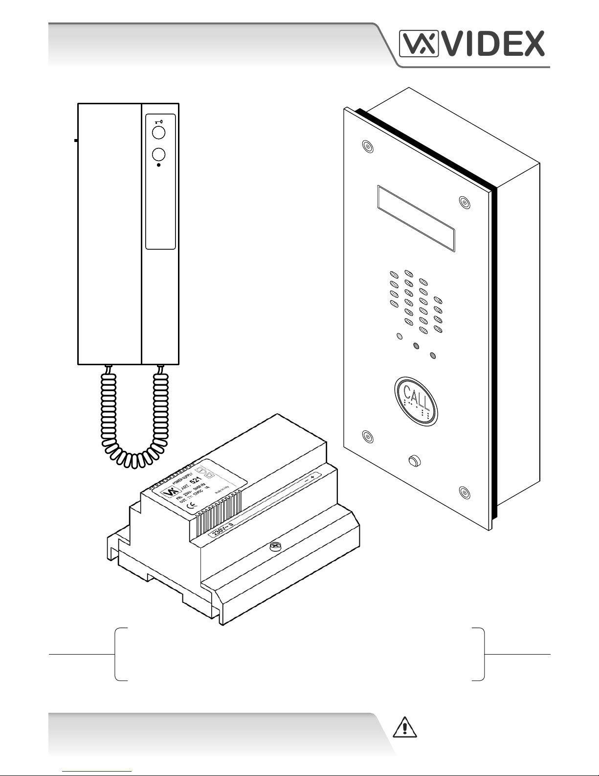
25H/SP/DDA/2W
(1 Way “2 Wire” DDA Audio Intercom Kit)
Technical Manual
25H/SP/DDA/2W EN-UK
V.1.2
04/01/16
WE RECOMMEND
This equipment is installed by a
Competent Electrician, Security
or Communications Engineer.
CALL
SPEAK BUSY OPEN
VIDEX
Page 2
25H/SP/DDA/2W - TECHNICAL MANUAL EN-UK - V.1.2 - 04/01/16
2
VIDEX
25H/SP/DDA/2W (1 way “2 wire” DDA audio intercom kit)
CUSTOMER SUPPORT
VIDEX SECURITY LTD
www.videxuk.com
Tech Line: 0191 224 3174
Fax: 0191 224 1559
Email: tech@videxuk.com
CE conformity marking indicates that the product respects the requirements
of the applicable European Community Directives in force specically EMC
2004/108/ECC, LVD 2006/95/ECC and CE-MARKING 93/68/ECC. CE marking is
applied by the manufacturer (or party delegated to do so by the manufacturer)
under their own responsibility. It was created to eliminate obstacles to the
circulation of products in European Union Member States by harmonising
dierent national standards.
Page 3

25H/SP/DDA/2W - TECHNICAL MANUAL EN-UK - V.1.2 - 04/01/16
3
VIDEX
25H/SP/DDA/2W (1 way “2 wire” DDA audio intercom kit)
CONTENTS
MANUAL INTRODUCTION.............................................................................................................................................. 4
SYSTEM INTRODUCTION................................................................................................................................................ 4
KIT COMPONENTS........................................................................................................................................................... 4
INTERCOM BACK BOXES................................................................................................................................................. 5
INTERCOM DOOR PANEL................................................................................................................................................ 6 - 7
SYSTEM OPERATION....................................................................................................................................................... 7
ART.138N AMPLIFIER UNIT FOR THE VX2200 SYSTEM................................................................................................. 8 - 10
ART.UIM-138 DISPLAY MODULE (FOR USE WITH THE ART.138N AMPLIFIER MODULE)........................................... 11 - 12
ART.3171 AUDIOPHONE................................................................................................................................................. 13
ART.521 POWER SUPPLY................................................................................................................................................. 14
SOFTWARE INSTALLATION AND SETUP......................................................................................................................... 15
THE MAIN PROGRAMMER SCREEN................................................................................................................................ 16 - 24
THE STATUS AND PROGRESS BAR.................................................................................................................................. 24 - 25
CABLE REQUIREMENTS.................................................................................................................................................. 26
BLOCK CABLE DIAGRAM................................................................................................................................................. 27
WIRING DIAGRAM........................................................................................................................................................... 28
LOCK RELEASE WIRING AND BACK EMF PROTECTION................................................................................................. 29
CONNECTION TO MAINS, SAFETY AND GUIDANCE NOTES......................................................................................... 29 - 30
POWER SUPPLY INSTALLATION...................................................................................................................................... 30 - 31
PANEL AND BACK BOX INSTALLATION........................................................................................................................... 31 - 33
PANEL CARE AND MAINTENANCE.................................................................................................................................. 34
POWERING UP THE ART.UIM-138 DISPLAY MODULE................................................................................................... 34
RESETTING THE ART.UIM-138 DISPLAY MODULE......................................................................................................... 35
QUICK USB DRIVER SETUP GUIDE.................................................................................................................................. 35
QUICK SOFTWARE SETUP GUIDE.................................................................................................................................... 35
TROUBLE SHOOTING....................................................................................................................................................... 36 - 37
NOTES............................................................................................................................................................................... 38 - 39
Page 4
25H/SP/DDA/2W - TECHNICAL MANUAL EN-UK - V.1.2 - 04/01/16
4
VIDEX
25H/SP/DDA/2W (1 way “2 wire” DDA audio intercom kit)
MANUAL INTRODUCTION
The information in this manual is intended as an installation and commissioning guide for the 25H/SP/
DDA/2W - 1 way “2 wire” DDA audio intercom kit. This manual should be read carefully before the installation
commences. Any damage caused to the equipment due to faulty installation where the information in this
manual has not been followed is not the responsibility of Videx Security Ltd.
A copy of this Technical Manual can also be downloaded from the Videx website: www.videxuk.com.
It is recommended that the audio intercom kit is installed by a competent electrician, security or
communications engineer.
VIDEX run free training courses for engineers who are unfamilier or who have not installed this kit before.
Technical help is also available on 0191 224 3174 during oce hours (8:30am - 5:00pm MON to FRI) or via
e-mail: tech@videxuk.com.
SYSTEM INTRODUCTION
The 25H/SP/DDA/2W - 1 way “2 wire” DDA audio intercom kit includes features to aid users with disabilities
and makes the process of calling an apartment more user friendly helping comply with the Equality Act 2010.
The intercom panel is manufactured from 12 gauge 316 grade vertically brushed stainless steel and
incorporates a ‘speak’, ‘busy’ and ‘door open’ call progress LEDs. An additional feature is the 2 line 16 digit
display which also includes speech annunciation and is used to indicate the progress of a call. It also has a
user friendly DDA compliant illuminated braille call button.
A ush back box (VRFB120x280) is standard in this kit, however a ush stainless steel bezel back box
(VRBB120x280) and a surface back box with rainshield (VRSB120x280) are also available on request (refer to
page 7).
Key Features Include:
• 12 gauge stainless steel intercom panel.
• Illuminated braille call push button.
• SPEAK, BUSY and OPEN call progress indication LEDs.
• Speech annunciation and call progress reassurance tones.
• Dry contact relay output.
• Timed call, speech and lock release.
• Speaker and microphone volume adjustment.
• Audiophone calltone volume adjustment.
KIT COMPONENTS
The kit includes the following parts:
• A 12 gauge stainless steel VR120 intercom panel with ‘built-in’ braille call button,
138N amplier and 138-UIM user interface display module (including ush back box
VRFB120x280).
• The Art.3171 audiophone (for the VX2200 digital system).
• The Art.521, 12Vdc 1A power supply boxed in a 9 module DIN box type A.
Page 5
25H/SP/DDA/2W - TECHNICAL MANUAL EN-UK - V.1.2 - 04/01/16
5
VIDEX
25H/SP/DDA/2W (1 way “2 wire” DDA audio intercom kit)
120mm
100mm 50mm
157mm 60mm
124mm 80mm
280mm
260mm50mm
317mm
284mm60mm
123mm
100mm 50mm
124mm 80mm
260mm50mm
284mm60mm
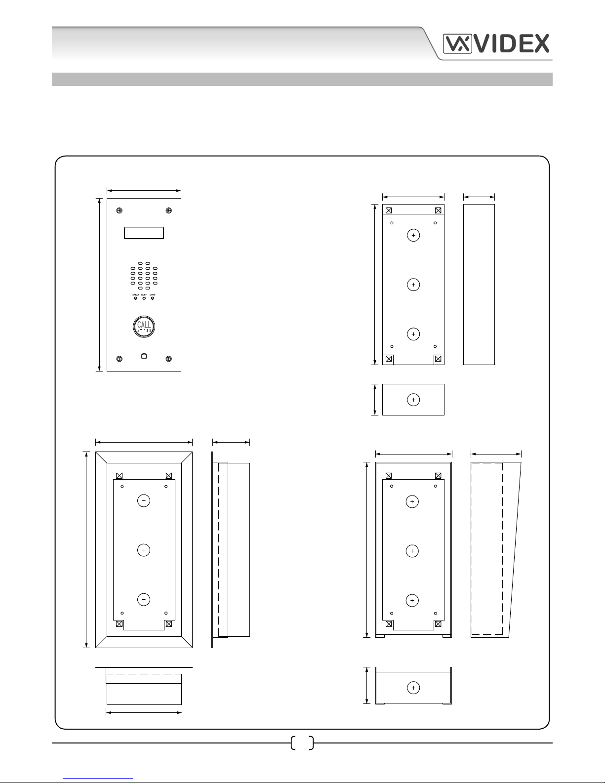
INTERCOM BACK BOXES
The DDA audio kit comes with a standard ush back box (VRFB120x280). A ush back box with bezel
(VRBB120x280) and a surface back box with rainshield (VRSB120x280), shown below, are also available on
request.
Back Box Dimensions
FRONT PANEL FLUSH (VRFB120x280)
FLUSH WITH BEZEL (VRBB120x280)
SURFACE WITH RAINSHIELD (VRSB120x280)
Page 6
25H/SP/DDA/2W - TECHNICAL MANUAL EN-UK - V.1.2 - 04/01/16
6
VIDEX
25H/SP/DDA/2W (1 way “2 wire” DDA audio intercom kit)
CALL
SPEAK BUSY OPEN
Art. UIM-138
User information module
Made in Italy
USB 0V A0 I1 I2 I3 I4 I5
Up Down High Low
1 2 3 4 5 6 7 8
ON
120mm
280mm
1
2
3
7
8
9
10
11
12
13
14
18
16
17
15
4
6
5
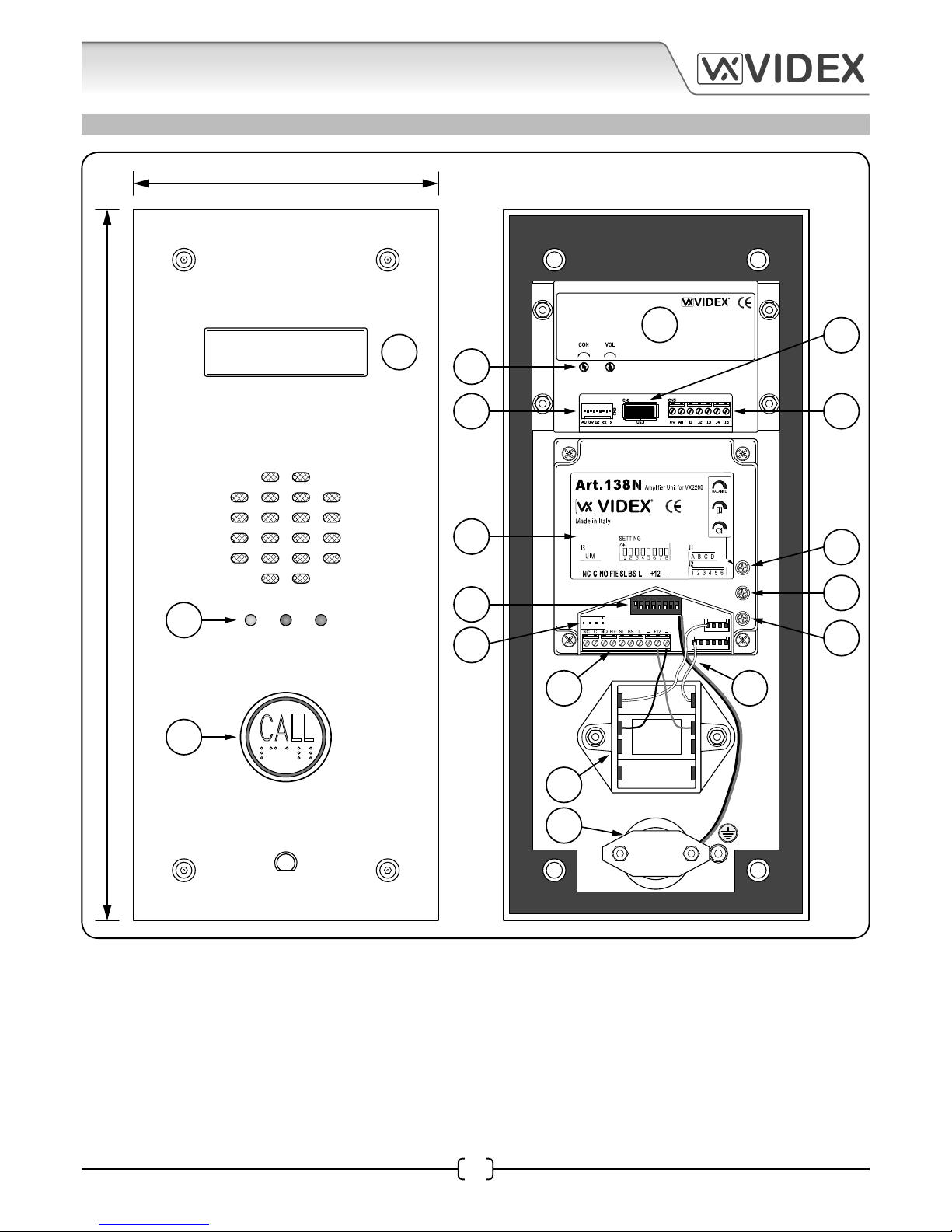
INTERCOM DOOR PANEL
Page 7
25H/SP/DDA/2W - TECHNICAL MANUAL EN-UK - V.1.2 - 04/01/16
7
VIDEX
25H/SP/DDA/2W (1 way “2 wire” DDA audio intercom kit)
1
2
3
4
5
8
6
7
10
11
17
16
15
12
14
9
18
13
UIM-138 (DDA) 2 line 16 digit display.
Call progress LEDs (speak, busy and open).
DDA Braille ‘CALL’ button.
UIM-138 User Information Module.
USB Laptop/PC connection.
UIM-138 Auxiliary inputs and output.
Display contrast and volume control adjustment.
UIM-138/Art.138N harness connection.
Art.138N Digital Functional Amplier Unit.
8 Way dip-switch (DSW1) settings.
UIM-138/Art.138N harness connection.
Art.138N terminal connections.
Pre-wired (US91-15) DDA braille push button.
Microphone.
Balance adjusment.
Speaker volume adjustment.
Microphone volume adjustment.
Pre-wired braille push button wires and
microphone cable.
SYSTEM OPERATION
In standby the door panel’s display will show ‘PRESS BUTTON TO CALL’ , the call button will be illuminated
and waiting to be pressed.
Upon pressing the button a reassurance tone will be heard at the door panel, the busy LED on the panel will
switch ON and the display will show ‘CALLING’ as the panel announces that it is calling the audiophone. The
audiophone will ring.
Once the audiophone is answered the speak LED will switch ON and the display will show ‘SPEAK’. The
speech will be live between the panel and audiophone.
When the lock button on the audiophone is pressed the open LED will switch ON, the display will show
‘OPEN’ and the panel will emit a series of beeps to indicate the panel’s relay is being triggered. The panel will
also announce ‘THE DOOR IS OPEN’.
Once the call ends and the audiophone recieiver has been replaced the busy LED will switch OFF and the
display will show ‘END’. The panel will go back into standby.
Page 8
25H/SP/DDA/2W - TECHNICAL MANUAL EN-UK - V.1.2 - 04/01/16
8
VIDEX
25H/SP/DDA/2W (1 way “2 wire” DDA audio intercom kit)
Switch 4 on the Art.138N is used to setup the
conversation time between the intercom panel
and the audiophone.
Switch 5 on the Art.138N is used to program the
door relay time.
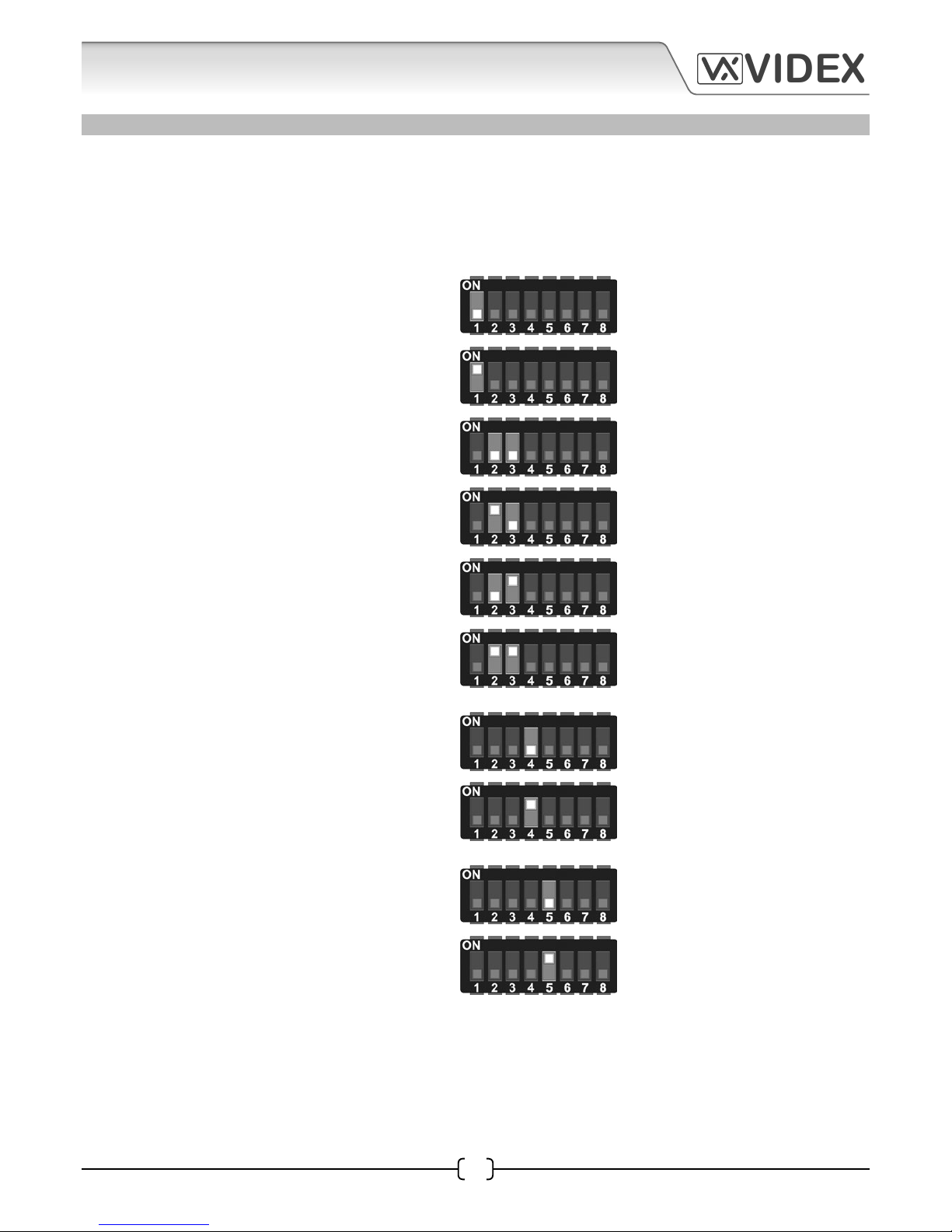
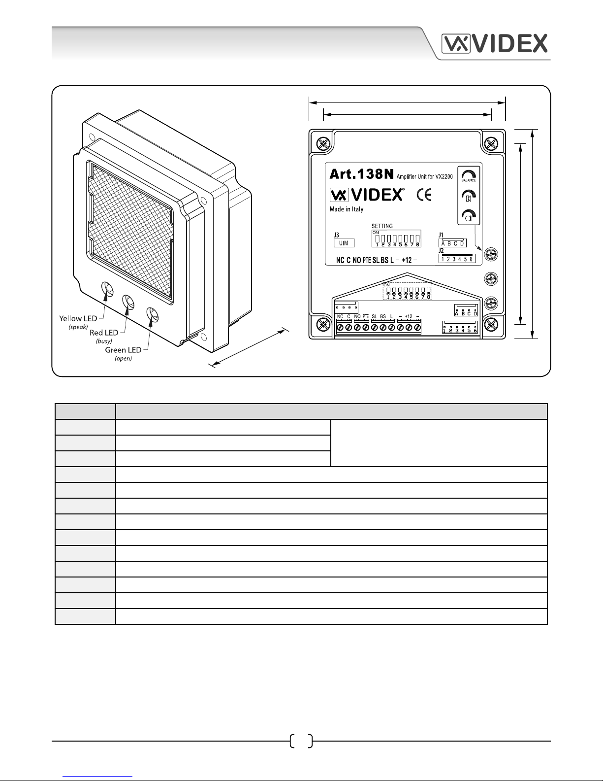
ART.138N AMPLIFIER UNIT FOR THE VX2200 SYSTEM
The Art.138N is a functional digital amplier unit based on the “2 wire” BUS intercom for the VX2200 system.
Although the Art.138N amplier unit can be connected up to 24 call buttons the 25H/SP/DDA/2W panel will
already have a US91-15 DDA friendly braille push button pre-wired into the J1 and J2 button harness (using
the yellow (1) and white (A) wires).
The amplier can be congured as a MASTER
or a SLAVE panel depending on the number of
Art.138N ampliers connected on a system, this
can be done by adjusting switch 1 on the 8 way
dip-switch. The default setting is MASTER (switch
1 in the ON position).
Dip-Switch Settings (DSW1)
Switches 2 and 3 on the Art.138N congures the
24 push button group indicating the ID’s on the
phones which can be called.
switch 1 OFF = SLAVE
switch 1 ON = MASTER
switch 2 OFF
switch 3 OFF
button group
1 - 24
switch 2 ON
switch 3 OFF
button group
25 - 48
switch 2 OFF
switch 3 ON
button group
49 - 72
switch 2 ON
switch 3 ON
button group
73 - 96
switch 4 OFF = 1 minute
switch 4 ON = 2 minutes
switch 5 OFF = 2 seconds
switch 5 ON = 6 seconds
Page 9
25H/SP/DDA/2W - TECHNICAL MANUAL EN-UK - V.1.2 - 04/01/16
9
VIDEX
25H/SP/DDA/2W (1 way “2 wire” DDA audio intercom kit)
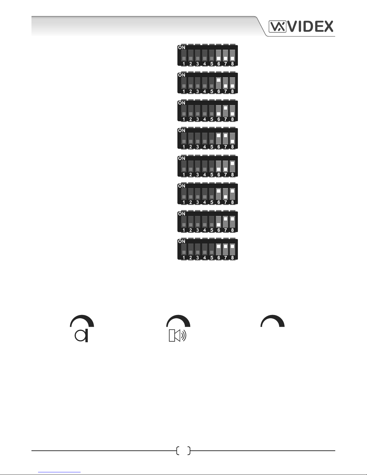
BALANCE
Switches 6, 7 and 8 are used to setup the device
number of the Art.138N (these switches are usually
only set when there is a VX2210 concierge unit on
the system where the intercom panel making the
call needs to be identied on the concierge. It is
also used on video systems when camera recall is
required for each door).
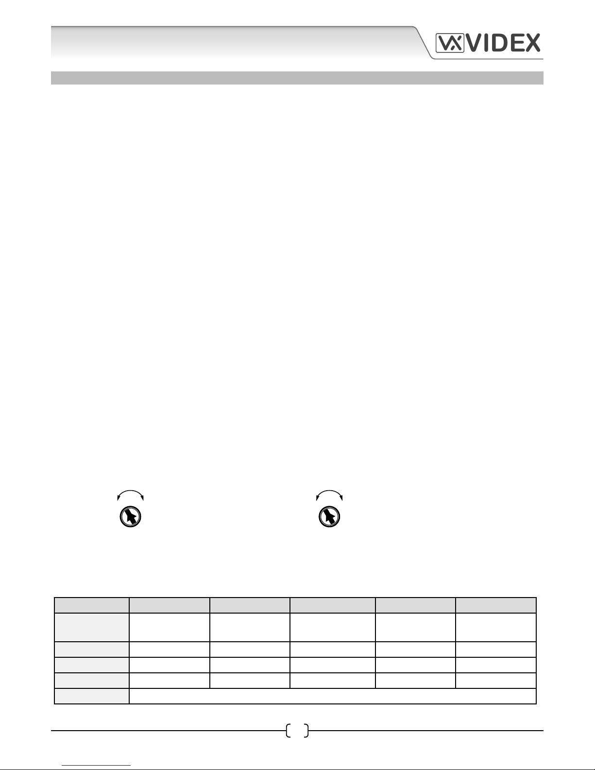
Volume Adjustments
There are three adjustable POTs available on the Art.138N amplier module for speech volume adjustment.
This system uses only one wire to carry both directions of speech and so it is necessary to use the balance
POT to adjust the gain of the two speech directions to the required levels*.
microphone volume
adjustment
speaker volume
adjustment
balance control for
microphone and speaker
switch 6 OFF
switch 7 OFF
switch 8 OFF
= device 1
switch 6 ON
switch 7 OFF
switch 8 OFF
= device 2
switch 6 OFF
switch 7 ON
switch 8 OFF
= device 3
switch 6 ON
switch 7 ON
switch 8 OFF
= device 4
switch 6 OFF
switch 7 OFF
switch 8 ON
= device 5
switch 6 ON
switch 7 OFF
switch 8 ON
= device 6
switch 6 OFF
switch 7 ON
switch 8 ON
= device 7
switch 6 ON
switch 7 ON
switch 8 ON
= device 8
(*Volume adjustment tip: set the speaker and mic POTs to approximately a third of a turn and then during ‘live’
speech adjust the balance POT whilst rubbing the bottom of the mic cap. Continue adjusting the balance POT to
the point at which the minimum volume of speech comes through the door panel’s speaker. Finally adjust the
speaker and mic POTs to optimal level ensuring that no feedback occurs when the panel is placed back into the
back box).
Page 10
25H/SP/DDA/2W - TECHNICAL MANUAL EN-UK - V.1.2 - 04/01/16
10
VIDEX
25H/SP/DDA/2W (1 way “2 wire” DDA audio intercom kit)
80mm
68mm
73mm
85mm
35mm
Terminal Connections
Terminal Description
NC Normally closed relay contact
current rating 3A @ 120Vac
current rating 3A @ 24Vdc
C Common relay contact
NO Normally open relay contact
PTE Push to exit input (active low, when triggered will activate the door open relay)
SL Active low output (active during a call)
BS Busy signal (active low input/output during a call)
L BUS line data input
- BUS line ground input
+12 +12Vdc power supply input
- (GND) Power supply ground input
J1 Pins A - D button matrix column terminals (button commons)
J2 Pins 1 - 6 button matrix row terminals
J3 UIM harness connection (for connection of UIM-138 display module)
Technical Specications
Memory Capacity : up to 24 users
Working Voltage : 13Vdc +/- 10%
Max. Current : approx. 350mA
Working Temp. : -10 +50oC
Art.138N Module Dimensions
Page 11
25H/SP/DDA/2W - TECHNICAL MANUAL EN-UK - V.1.2 - 04/01/16
11
VIDEX
25H/SP/DDA/2W (1 way “2 wire” DDA audio intercom kit)
Up Down High
Low
CON VOL
Low
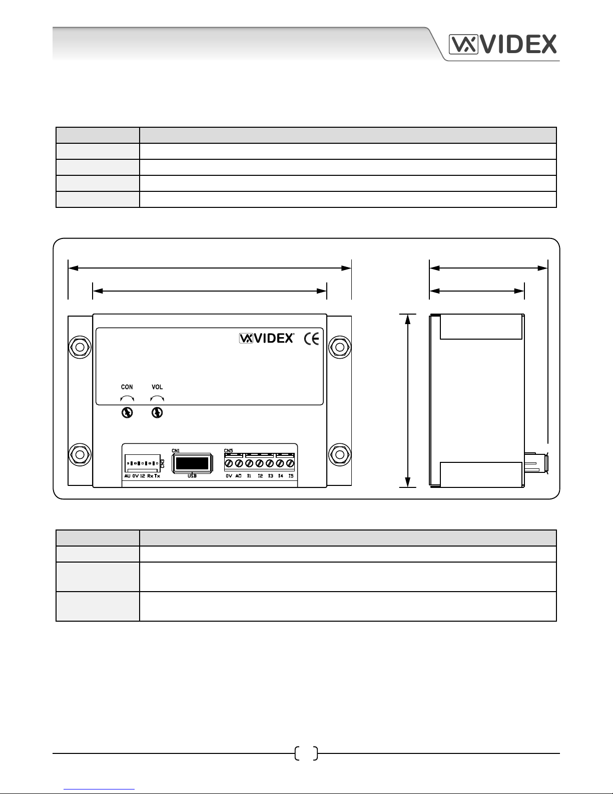
ART.UIM-138 DISPLAY MODULE (FOR USE WITH THE ART.138N AMPLIFIER MODULE)
The UIM-138 display module is designed to interface with the 138N amplier module for the VX2200 system
bringing features normally only found on digital door panels to the traditional call button panels. Additional
features are included to aid users with disabilities and make the process of calling an apartment more user
friendly helping comply with the Equality Act 2010.
The 2 line 16 character blue back lit LCD display is protected behind a 6mm Lexan window and shows call
progress information while also producing spoken call progress messages through the speaker of the 138N
amplier.
The UIM-138 can be programmed using the current VX2X00 programming software (version 7.0.0.7 or later)
allowing user names, apartment numbers and additional displayed messages to be programmed. The
module connects to the 138N amplier module via a ‘plug-in’ wire harness and connects to a PC or laptop
via a standard USB connection.
Key Features Include:
• 2 line 16 character blue back lit display.
• Voice annunciation output.
• 5 programmable auxiliary inputs.
• A switched 0V auxiliary output..
• USB port.
• Display contrast and voice annunciation volume adjustments.
Display Contrast and Voice Annunciation Volume Controls
There are two control POTs available on the UIM-138 module for adjusting the display contrast and the voice
annunciation volume.
display contrast
adjustment
voice annunciation
volume adjustment
Auxiliary Input Modes
The UIM-138 module has 5 programmable auxiliary inputs. The table below shows the operating modes
available for each input and is set using the PC software.
Mode I1 (Aux 1) I2 (Aux 2) I3 (Aux 3) I4 (Aux 4) I5 (Aux 5)
1 Auxiliary 1
message
Auxiliary 2
message
Auxiliary 3
message
Auxiliary 4
message
Auxiliary 5
message
2 Call ID.1 Activate AO
currently unavailable
End call Activate relay
3 Scroll < (back) Call Scroll > (forward)
currently unavailable
End call
4 Call ID.25 Call ID.26 Call ID.27 Call ID.28 Call ID.29
5 - 10 currently unavailable, left for future expansion
Page 12
25H/SP/DDA/2W - TECHNICAL MANUAL EN-UK - V.1.2 - 04/01/16
12
VIDEX
25H/SP/DDA/2W (1 way “2 wire” DDA audio intercom kit)
Art. UIM-138
User information module
Made in Italy
USB 0V A0 I1 I2 I3 I4 I5
Up Down High Low
96mm
80mm
40mm
32mm
60mm
Auxiliary Output Modes
The UIM-138 module has a single programmable auxiliary output. The table below shows the operating
modes available for this output and is set using the PC software.
Mode AO (Auxiliary Output)
1 Auxiliary output triggered by auxiliary input I2
2 Auxiliary output triggered for duration of call
3 Auxiliary output triggered for auxiliary output time at beginning of call
4 - 10 currently unavailable, left for future expansion
Art.UIM-138 Display Module Dimensions
Terminal Connections
Connection Description
0V 0V ground input
AO Programmable auxiliary output (this is an open collector output, switched 0V. Please refer
to the table above for full list of programmable output modes).
I1 - I5 5 programmable auxiliary inputs, switched 0V trigger (please refer to the table on page 9
for full list of programmable input modes).
Technical Specications
Input Voltage : 12-14Vdc +/- 10%
Current (standby) : approx. 29mA
Current (during operation) : approx. 34mA (max.)
Harness Connection : 5 way pin connector
USB port : USB
Module Dimensions : 80mm (L) x 60mm (W) x 32mm (D)
Working Temp. : -10 +50oC
Page 13

25H/SP/DDA/2W - TECHNICAL MANUAL EN-UK - V.1.2 - 04/01/16
13
VIDEX
25H/SP/DDA/2W (1 way “2 wire” DDA audio intercom kit)
ART.3171 AUDIOPHONE
The Art.3171 audiophone includes a three position call tone volume control, lock release push button and
spare dry contact ‘push-to-make’ button for other services. Up to three telephones can be connected in
parallel on this system. A local door bell (LB terminal) is also available. Connecting a push switch between LB
& - will ring the telephone to inform the occupant that someone is at their door (the local bell audible ringing
tone is dierent to the call tone from the intercom panel).
A minimum of 2 cores are required to connect the Art.3171 audiophone to the Art.138N amplier module.
For internal use a CW1308 twisted pair telephone cable is recommended and for external use a CW1128
twisted pair telephone cable is recommended.
Audiophone Dip-Switch Settings
Internally the Art.3171 audiophone has an 8 way dip-switch to set up the phone ID and is based on binary
addressing (for the 25H/SP/DDA/2W audio kit the default address for the Art.3171 audiophone should be set to
phone ID.1 as shown below).
Dip-Switch No. 1 2 3 4 5 6 7 8
ON OFF OFF OFF OFF OFF OFF OFF
VIDEX
1 2 3 4 5 6 7 8
ON
SW1
L
_
LB
AL
SW
SW
VR1
85mm
218mm
Terminal Function
L BUS line data input
- BUS line ground input
LB Local Bell input (switched 0V)
AL Alarm input (switched 0V, for use with
concierge)
SW Dry contact switch connections
SW
Technical Specication
Bus Voltage : 7.5Vdc
Current (during call) : 15.5mA
Current (during
conversation)
: 78mA
Current (during lock
release)
: 80 - 105mA (max.)
Audiophone
Dimensions
: 85mm (W) x 218mm
(L) x 55mm (D)
Working Temp. : -10 +50oC
Art.3171 Terminal Connections and Dimensions
Page 14

25H/SP/DDA/2W - TECHNICAL MANUAL EN-UK - V.1.2 - 04/01/16
14
VIDEX
25H/SP/DDA/2W (1 way “2 wire” DDA audio intercom kit)
ART. 521
POWER SUPPLY
Made in EEC
PRI.
OUT.
230V
12VDC 1A
50/60Hz
230V 0
157.5mm 65mm
105mm
ART.521 POWER SUPPLY
The Art.521 power supply will supply an output voltage of 13.5Vdc (800mA continuous or a 1A surge) and is
protected by a fall back circuit (there are no internal fuses on the primary or secondary side of the transformer).
A fused spur should always be used with this type of power supply. It is contained in a standard 9 module A
type DIN box for mounting on a standard DIN rail.
IMPORTANT NOTE: The 230Vac mains input terminals on this PSU should be connected to the mains supply
via a fused spur or preferably an all pole circuit breaker (refer to pages 29 - 30).
Art.521 Dimensions
Terminal Connections
Terminal Function
+ 13.5Vdc output (800mA continuous, 1A max.)
- 0V (ground)
230V~ Mains input (live)
0V Mains input (neutral)
Technical Specications
Input Voltage : 230Vac @ 50/60Hz +/- 10%
Output Voltage : 13.5Vdc +/- 10%
Current (continuous) : 800mA, (surge 1A max.)
Module Dimensions : 157.5mm (L) x 105mm (W) x 65mm (D)
Working Temp. : -10 +50oC
Page 15

25H/SP/DDA/2W - TECHNICAL MANUAL EN-UK - V.1.2 - 04/01/16
15
VIDEX
25H/SP/DDA/2W (1 way “2 wire” DDA audio intercom kit)
USB
PORT
UIM-138 WIRING
HARNESS CONNECTED
TO 138N AMPLIFIER
PC DISPLAY MODULE
USB CABLE
OPTIONAL AUXILIARY
INPUT/OUTPUT
CONNECTIONS
SOFTWARE INSTALLATION AND SETUP
Before connecting the UIM-138 module to a PC or laptop please ensure that the USB driver has been installed
from the software CD (refer to the quick USB driver setup guide on page 35).
Launch the 2X00PC software by
double clicking on the desktop icon.
The initial launch window will appear (as shown to the right). At
the top of the window the software will show that it is checking
for any devices connected to the PC or laptop.
SOFTWARE INSTALLATION AND SETUP
Launching the Software
Fig.1
After the USB driver has been installed ensure that the UIM-138 is connected to the 138N speaker amp using
the ‘plug-in’ wire harness and any necessary auxiliary inputs/outputs are connected (this will depend on the
users requirements). Ensure that the latest VX2X00 version of software is installed on the PC or laptop (version
7.0.0.7 or later, refer to the quick software setup guide on page 35) and there is 12Vdc power connected into the
138N amplier. After the software is installed connect the UIM-138 display module to the PC or laptop using
the USB cable provided, as shown in Fig.1 below.
Page 16

25H/SP/DDA/2W - TECHNICAL MANUAL EN-UK - V.1.2 - 04/01/16
16
VIDEX
25H/SP/DDA/2W (1 way “2 wire” DDA audio intercom kit)
After a brief period the main programmer screen will appear.
If a device has been detected this will be shown at the bottom of the main programmer screen with a green
square (see below). On this screen several programming options can be selected.
The main programmer screen shows several menu options at the top (although several menu options are
shown at the top not all options will be applicable when using the UIM-138 display module) and two selectable
windows on the main screen; ‘settings’ and ‘apartments’. The default tab selected is the ‘settings’ tab and the
main display logo eld will already have ‘ENTER FLAT’ inserted into the eld and the speech playback eld
will already have ‘combined’ selected from the drop down menu (seen at the top of the settings window).
Under the ‘settings’ tab the following elds can be edited:
• Main Display Logo - the main logo text can be entered into each eld line. (The information entered into
these elds will be the main logo shown on the UIM-138 display).
• Switch Display Logo - the switch logo text can be entered into each eld line. (The information entered
into these elds will alternate between the main display logo, approximately every 5 seconds).
• Aux. 1, Aux. 2, Aux. 3, Aux. 4 and Aux 5 display text - additional text can be entered into each auxiliary
eld line. (The information entered into these elds will be shown on the UIM-138 display after the respective
auxiliary input I1, I2, I3, I4 or I5 has been triggered).
• Aux. Out Time - the auxiliary output time can be set (in seconds, from 1 to 99 seconds) in this eld.
Each heading on the left of the ‘settings’ window consists of two
editable eld lines with up to 16 characters each. To the right of each
eld line there is a ‘centre alignment’ button (as shown on the right)
which allows the text entered into the eld line to be centred when
shown on the UIM-138 display.
Settings
THE MAIN PROGRAMMER SCREEN
Page 17

25H/SP/DDA/2W - TECHNICAL MANUAL EN-UK - V.1.2 - 04/01/16
17
VIDEX
25H/SP/DDA/2W (1 way “2 wire” DDA audio intercom kit)
On the right of the ‘settings’ tab there are 7 selectable options each with a drop down menu where the
following can be set:
• Speech Playback - the default setting in this eld is set to ‘combined’. By clicking on the drop down
menu button (q) on the right of the eld this setting can be changed. The three options available are:
none, individual and combined (if ‘none’ is selected then there will be no speech playback when a call is
made to the at. If ‘individual’ is selected then the speech annunciation will playback the individual numbers
that make up the at number e.g. if calling at 25 the speech will playback “calling two ve”. If ‘combined’ is
selected then the speech annunciation will playback the combined at number e.g. if calling at number 15
the speech will playback “calling fteen”).
1. Aux.1 Message - when set into mode 1 the text entered into the ‘Aux.1 display text’ elds
will be shown on the UIM-138 display.
2. Call ID.1 - when set into mode 2 the UIM-138 will trigger the 138N speaker amp to call
phone ID.1 (particularly useful if a 2210A or 2210V concierge unit is being used).
3. Scroll < (back) - when set into mode 3 then the UIM-138 display will scroll up through the
list of programmed ats that have been setup in the ‘name’ eld under the ‘apartments’
tab (refer to page 19 ).
4. Call ID.25 - when set into mode 4 the UIM-138 will trigger the 138N speaker amp to call
phone ID.25.
• Aux.2 Mode - the following modes can be set and will be active when auxiliary input I2 is triggered:
1. Aux.2 Message - when set into mode 1 the text entered into the ‘Aux.2 display text’ elds
will be shown on the UIM-138 display.
2. Activate AO - when set into mode 2 the UIM-138 display will trigger the AO output.
3. Call - when set into mode 3 then the UIM-138 display will allow a call to be made to a at
that has been selected using the scroll up/down buttons.
4. Call ID.26 - when set into mode 4 the UIM-138 will trigger the 138N speaker amp to call
phone ID.26.
• Aux.3 Mode - the following modes can be set and will be active when auxiliary input I3 is triggered:
1. Aux.3 Message - when set into mode 1 the text entered into the ‘Aux.3 display text’ elds
will be shown on the UIM-138 display.
2. MODE 2 - currently unavailable, left for future expansion.
3. Scroll > (forward) - when set into mode 3 then the UIM-138 display will scroll down
through the list of programmed ats that have been setup in the ‘name’ eld under the
‘apartments’ tab (refer to page 19).
4. Call ID.27 - when set into mode 4 the UIM-138 will trigger the 138N speaker amp to call
phone ID.27.
• Aux.1 Mode - the following modes can be set and will be active when auxiliary input I1 is triggered:
Clicking on the drop down menu button (q) on the right of the eld the required auxiliary mode can be set
(a table of auxiliary input modes can be found on page 11):
Page 18

25H/SP/DDA/2W - TECHNICAL MANUAL EN-UK - V.1.2 - 04/01/16
18
VIDEX
25H/SP/DDA/2W (1 way “2 wire” DDA audio intercom kit)
• Aux.4 Mode - the following modes can be set and will be active when auxiliary input I4 is triggered:
1. Aux.4 Message - when set into mode 1 the text entered into the ‘Aux.4 display text’ elds
will be shown on the UIM-138 display.
2. End Call - when set into mode 2 the UIM-138 display will trigger the 138N speaker amp
to end the call made to a at.
3. MODE 3 - currently unavailable, left for future expansion.
4. Call ID.28 - when set into mode 4 the UIM-138 will trigger the 138N speaker amp to call
phone ID.28.
• Aux.5 Mode - the following modes can be set and will be active when auxiliary input I5 is triggered:
1. Aux.5 Message - when set into mode 1 the text entered into the ‘Aux.5 display text’ elds
will be shown on the UIM-138 display.
2. Activate Relay - when set into mode 2 the UIM-138 display will trigger the 138N speaker
amp to activate it’s onboard relay.
3. End Call - when set into mode 3 then the UIM-138 display will trigger the 138N speaker
amp to end the call made to a at.
4. Call ID.29 - when set into mode 4 the UIM-138 will trigger the 138N speaker amp to call
phone ID.29.
• Aux. Out Mode (AO) - by clicking on the drop down menu button (q) on the right of the eld the
required auxiliary output mode can be set (refer to the table on page 12). The following modes can be set:
1. MODE 1 (Aux. Out triggered by auxiliary input I2) - when set into mode 1 the auxiliary
output AO will activate for the time period setup in the ‘Aux. Out Time’ eld (described
on page 16). The AO will activate when auxiliary input I2 has been triggered, but only if
auxiliary input 2 has been set up in mode 2 (refer to Activate AO on page 17).
2. MODE 2 (Aux. Out triggered for duration of call) - when set into mode 2 then the AO
output will activate for the entire duration of the call (from when the call button is pressed
on the panel until the handset is hung up in the at).
3. MODE 3 (Aux. Out triggered for Aux. Out Time at the beginning of the call ) - when set
into mode 3 the auxiliary output AO will activate for the time period setup in the ‘Aux.
Out Time’ eld (described on page 16). The AO will activate from when the call button on
the panel is pressed until the ‘Aux. Out Time’ expires.
Page 19

25H/SP/DDA/2W - TECHNICAL MANUAL EN-UK - V.1.2 - 04/01/16
19
VIDEX
25H/SP/DDA/2W (1 way “2 wire” DDA audio intercom kit)
The ‘apartments’ tab is set out with 6 columns; Mem, Apt No., Phone ID, Block ID, Access Code and Name (as
shown below) and several eld rows. The ‘Mem’ column (memory location) is already completed.
Under the ‘apartments’ tab the following elds can be edited:
• Apt No. - the apartment number or at number can be entered into this eld (The apartment number
entered into this eld will be shown on the top line of the UIM-138 display when a call is made to that
apartment).
• Phone ID - the address of the intercom phone in the apartment can be entered into this eld.
• Block ID - if an Art.2206N bus exchange device is used then the block ID can be entered into this eld.
(Information completed in this eld will only be applicable on multiple entrance systems where an Art.2206N
bus exchange device has been used).
• Access Code - this eld is not used.
• Name - the name of the user or the apartment or oce name can be entered into this eld and will be
available to select if the ‘scroll and call’ modes (described on page 17) have been setup on auxliliary inputs
I1, I2 and I3 on the UIM-138 display. (The information entered into this eld will be shown on the second line
of the UIM-138 display when a call is made to that apartment).
Apartments
At the top of the main programmer screen there are 9 menu options available: File, System, Download,
Upload, Sort, Language, Communication, Baud and About. As previously mentioned on page 16 not all of
these menu options are applicable when using the UIM-138 display module.
From the top menu on the main programmer screen when ‘File’ is selected the following drop down menu
will appear (as shown on page 20) and the following options are available:
File
Programmer Screen Top Menu
Page 20

25H/SP/DDA/2W - TECHNICAL MANUAL EN-UK - V.1.2 - 04/01/16
20
VIDEX
25H/SP/DDA/2W (1 way “2 wire” DDA audio intercom kit)
• New - selecting this option from the drop down menu will allow a new
database le to be created and saved.
• Open - selecting this option from the drop down menu will open an existing
database le that has previously been saved. (The le path location and le
name will be shown at the top of the programmer screen, see below).
• Open Recent u - Select this option from
the drop down menu and a list of the most
recent database les that were previously
accessed will be shown. To open select and
click on the relevent le required and the
‘settings’ and ‘apartment’ tabs will show the
saved database information.
• Save - select this option from the drop down menu to save the database le that is open.
• Save As - select this option from the drop down menu to save the database le in a specic le location
(a specied le path and location can be selected as shown below).
• Print - select this option from the drop down menu to print out the settings and the database le (as
shown on page 21).
Page 21

25H/SP/DDA/2W - TECHNICAL MANUAL EN-UK - V.1.2 - 04/01/16
21
VIDEX
25H/SP/DDA/2W (1 way “2 wire” DDA audio intercom kit)
• Exit - select this option when all programming is nished to exit out of the programmer software. (please
note that when exiting out of the programmer software a prompt window will appear asking if you want to
save the current le before exiting, click on the required button. If saving the le again it will be saved in the
same le location as described above under the ‘save as’ function).
From the top menu on the main programmer
screen when ‘System’ is selected the following drop
down menu will appear (as shown). There are four
options shown on the drop down list, however the
‘UIM-138’ option will already be ticked. The other
three options will not be applicable this is because
when the programmer software rst loads up it will
automatically detect that a UIM-138 display module
is connected.
System
Download
From the top menu on the main programmer screen
when ‘Download’ is selected the following drop
down menu will appear (as shown). Clicking on
‘Download All’ will download all the programming
from the existing UIM-138 display module that the
programmer software is connected to.
Page 22

25H/SP/DDA/2W - TECHNICAL MANUAL EN-UK - V.1.2 - 04/01/16
22
VIDEX
25H/SP/DDA/2W (1 way “2 wire” DDA audio intercom kit)
Upload
From the top menu on the main programmer screen
when ‘Upload’ is selected the following drop down
menu will appear (as shown on the right). From the
drop down list the following options are available:
• Upload All - selec t this option from the drop down
menu to upload all the information entered into
the ‘settings’ and ‘apartment’ windows. (Once the
‘Upload All’ option has been selected from the drop
down list the ‘master code’ window will appear, as
shown on the right. The ‘master code’, ‘connected
to’ and ‘rmware version’ options will all be greyed
out as these options are not applicable when using
the UIM-138 display module. Simply click on the
‘start’ button to upload or the ‘cancel’ button to exit
out of this option. Please note that when uploading the display will show ‘please wait’ and a progress bar will
be shown on the second line of the display, once complete it will then display ‘OK’ and then revert to the new
message).
• Upload Only Blocks - select this option from the drop down menu to upload information relating to a
specic block (the block number from the drop down list, as shown below, relates to the block ID entered into
the Block ID eld in the ‘apartments’ window as described on page 19. This option is generally used on larger
multiple entrance systems where an Art.2206N bus exchange device has been used. In most cases the ‘Upload
All’ option described above would be used).
The block ID in this eld relates to
the block ID number in the block ID
column in the apartments ‘tab’.
Page 23

25H/SP/DDA/2W - TECHNICAL MANUAL EN-UK - V.1.2 - 04/01/16
23
VIDEX
25H/SP/DDA/2W (1 way “2 wire” DDA audio intercom kit)
• Speed - this option from the drop down
menu determines how quickly the
information from the programmer software
uploads or downloads from the UIM-138
display (the default setting for this is set to 1
for the quickest speed).
• By Name - selecting this option
from the drop down menu will
arrange the list of programmed
apartments in the ‘apartments’
window in alphabetical order, as
shown on the right (if a print out
is selected from the drop down ‘le’
menu the print out will also show
this list in alphabetical order).
• By Apartment No. - selecting
this option from the drop down
menu will arrange the list of
programmed apartments in the
‘apartments’ window in numerical
order, as shown on the right (if a
print out is selected from the drop
down ‘le’ menu the print out will
also show this list in numerical
order).
From the top menu on the main programmer screen when ‘Language’ is selected the
following drop down menu will appear, as shown (the default language is English).
Sort
From the top menu on the main programmer screen when ‘Sort’ is selected
the following drop down menu will appear as shown to the right. From the
drop down list the following options are available:
Language
Page 24

25H/SP/DDA/2W - TECHNICAL MANUAL EN-UK - V.1.2 - 04/01/16
24
VIDEX
25H/SP/DDA/2W (1 way “2 wire” DDA audio intercom kit)
From the top menu on the main programmer screen when ‘Communication’
is selected the following drop down menu will appear, as shown below.
From the drop down list the following options are available:
• Comm Port - selecting this option from the drop
down menu will allow an available COM port to be
selected (please note that when the programmer
software loads up it will automatically detect if a
UIM-138 display is connected and automatically
select the COM port).
• Refresh List - selecting this option from the drop down menu will refresh the COM port drop down list
(please note that the COM port that the UIM-138 display is connected to will be included in the COM port drop
down list if it hasn’t already been included when the programmer software rst launched).
• Check Connection - selecting this option from the drop down menu will check and refresh the COM port
connection between the programmer software and the UIM-138 display module.
• Manually Connect - although shown in the drop down list this option is not applicable.
The baud rate 9600 will already be selected and all options greyed out. (When the programmer software rst
loads up it will automatically check through the COM ports, searching under dierent baud rates to see if the UIM138 display is connected).
This option conrms the current version of programming software being used.
The bottom of the main programmer screen indicates the current status of the programmer software and
its connection to the UIM-138 display module. The following notes describe the dierent statuses the
programmer software will show.
Upload
Baud
About
THE STATUS AND PROGRESS BAR
• Not Detected - this status is shown when the programmer software hasn’t detected a device (UIM-138
display module) attached to the PC, as shown below.
The ‘Refresh List’ option can be selected from the ‘Communication’ drop down list (from the top menu)
and the status bar will conrm that the ports list has been updated, this can be seen to the right of the
progress bar as shown below.
Page 25

25H/SP/DDA/2W - TECHNICAL MANUAL EN-UK - V.1.2 - 04/01/16
25
VIDEX
25H/SP/DDA/2W (1 way “2 wire” DDA audio intercom kit)
If the ‘Check Connection’ option is then selected from the ‘Communication’ drop down list the
programmer software will then search for the COM port that the display module is connected to and
re-establish a link. This can be seen to the right to the progress bar as shown below.
Once the COM port has been found by the programmer software the status bar will update. This can
be seen to the left of the progress bar. Conrmation of which COM port the UIM-138 display module
is connected to can be seen to the right of the progress bar as shown below.
• Detected - this status is shown when the programmer software has found a device (UIM-138 display
module) attached to the PC, as shown below.
• Opened File - this status is shown when the programmer software has successfully opened a saved
le using the ‘Open’ or ‘Open Recent’ option from the ‘File’ drop down list. The status will update to the
right of the progress bar as shown below.
• Saved File - this status is shown when the programmer software has successfully saved an open le
using the ‘Save’ or ‘Save As’ option from the ‘File’ drop down list. The status will update to the right of
the progress bar as shown below.
• Downloading Settings - this status is shown when the programmer software downloads all the existing
settings saved on the UIM-138 display module. This is done by selecting ‘Download All’ from the
‘Download’ drop down list from the top menu. The status and download progress can be seen to the
right of the progress bar as shown below.
• Uploading Settings - this status is shown when the programmer software uploads all the current
settings from an open le into the UIM-138 display module. This is done by selecting ‘Upload All’ from
the ‘Upload’ drop down list from the top menu. The status and upload progress can be seen to the right
of the progress bar as shown below.
Page 26

25H/SP/DDA/2W - TECHNICAL MANUAL EN-UK - V.1.2 - 04/01/16
26
VIDEX
25H/SP/DDA/2W (1 way “2 wire” DDA audio intercom kit)
CABLE REQUIREMENTS
The 25H/SP/DDA/2W audio kit follows the same cable requirements for the VX2200 (audio) system. The
following tables below show the minimum number of cable cores required for this audio kit.
Table B
Connection Min.
Cores
50m 100m 200m 300m
Art.3171 2
3 pair CW1308
or CAT5e
4 pair CW1308
or CAT5e
4 pair CW1308 or
4 core 0.5mm² YY
4 core 0.75mm² YY
(*2 Please Note: It is perfectly acceptable to use an equivalent cable type if a CW1308, CAT5e or a YY cable is
not being used providing it meets the same cable characteristics as those described above and those shown
in table B).
The Art.521 power supply should be located as close to the door panel as possible, typically between 20 to
30m (max.). The location of the power supply can also serve as a central point for the Art.3171 audiophone
connections. Any electric door lock and push-to-exit connections can be cabled directly back to the intercom
door panel. If tting a break glass unit then it should only be wired with a fail safe lock and in series with the
lock. The maximum acceptable resistance for all of these connections = 3Ω (ohms) or less for best possible
performance. Table A below shows the recommended cable type to use*1.
Power Supply, Lock Release, Push to Exit and Break Glass Connections
Table A
Connection 20m 30m (max.)
Art.521 Power Supply 2 core YY @ 0.5mm² 2 core YY @ 0.75mm²
Lock Release 2 core YY @ 0.5mm² 2 core YY @ 0.75mm²
Push to Exit 2 core YY @ 0.5mm² 2 core YY @ 0.75mm²
Break Glass 2 core YY @ 0.5mm² 2 core YY @ 0.75mm²
(*1 Please Note: It is perfectly acceptable to use an equivalent cable type if a 2 core YY cable is not being used
providing it meets the same cable characteristics as those described above and those shown in table A).
Art.3171 Audiophone Connections
The Art.3171 audiophone requires a 2 core databus connection (L and -) with a maximum acceptable
resistance of 7.5Ω (ohms) or less. For the databus connections a twisted pair cable should be used. Doubling
up on these connections to increase the CSA (cross sectional area) of the connection and reduce the
overall resistance is acceptable, however it should be noted that wherever possible no more than 2 cores
per connection should be used as this can cause an increase in capacitance of the cable. The maximum
acceptable resistance for all of these connections = 7.5Ω (ohms) or less for best possible performance. Table
B below shows the recommended cable type to use*2 and the cable distance shown is the overall cable run
between the intercom door panel via the central point, where the power supply (Art.521) is located, up to
and including where the Art.3171 audiophone is located. If more than one intercom door panel is used on
the system (multiple entrance system) then an additional core for the BSY (busy) connection will be required,
but will only need to be connected between the central point and the intercom door panels being used.
IMPORTANT NOTE: Please be aware that when selecting a cable for this audio kit the following should NOT
be used: Copper Coated Steel (CCS) and Copper Clad Aluminium (CCA). While these types of cable may oer
a low cost solution they will have a higher resistance than pure copper cable and can aect the overall
performance of the system therefore Videx DO NOT recommend these types of cable.
Page 27

25H/SP/DDA/2W - TECHNICAL MANUAL EN-UK - V.1.2 - 04/01/16
27
VIDEX
25H/SP/DDA/2W (1 way “2 wire” DDA audio intercom kit)
5
2
2
2 2
Art.3171
Audiophone
Central Point
PTE
BREAK GLASS
Fail Safe
Lock Release
25H/SP/DDA/2W
Intercom Door Panel
20m - 30m (max.)
PRESS TO
RELEASE
EMERGENCY
DOOR RELEASE
BREAK GLASS
PRESS HERE
ART. 521
POWER SUPPLY
Made in EEC
PRI.
OUT.
230V
12VDC 1A
50/60Hz
230V 0
Mains
VIDEX
BLOCK CABLE DIAGRAM
Fig.2 below shows the minimum number of cable cores required for a 1 entrance 25H/SP/DDA/2W audio kit
using the information taken from the tables shown on page 26.
Fig.2
Page 28

25H/SP/DDA/2W - TECHNICAL MANUAL EN-UK - V.1.2 - 04/01/16
28
VIDEX
25H/SP/DDA/2W (1 way “2 wire” DDA audio intercom kit)
+
-
VIDEX
1 2 3 4 5 6 7 8
ON
SW1
VR1
L
LB
AL
SW
SW
ART. 521
POWER SUPPLY
Made in EEC
PRI.
OUT.
230V
12VDC 1A
50/60Hz
230V 0
230Vac
50/60Hz
Mains Input
Art. UIM-138
User information module
Made in Italy
USB 0V A0 I1 I2 I3 I4 I5
Up Down High Low
1 2 3 4 5 6 7 8
ON
PRESS TO
RELEASE
NC
NO
CO
NC
NO
CO
EMERGENCY
DOOR RELEASE
BREAK GLASS
PRESS HERE
INTERCOM DOOR PANEL
Art.3171 Audiophone
12Vdc Fail Safe
Lock Release
CENTRAL CONTROL EQUIPMENT
1N4002 DIODE
= pre-wired
1 2 3 4 5 6 7 8
ON
Phone ID.1
1 2 3 4 5 6 7 8
ON
Switch 1 set
ON for MASTER
The Art.521 power supply
requires 230Vac mains input
WIRING DIAGRAM
Page 29

25H/SP/DDA/2W - TECHNICAL MANUAL EN-UK - V.1.2 - 04/01/16
29
VIDEX
25H/SP/DDA/2W (1 way “2 wire” DDA audio intercom kit)
+
-
100nF CAP 1N4002 DIODE
LOCK RELEASE WIRING AND BACK EMF PROTECTION
When fitting an electric lock release back EMF protection will be required. If fitting an AC lock release
then a 100nF ceramic disc capacitor must be fitted across the terminals on the lock and if fitting a DC
lock release (fail secure or fail safe) then a 1N4002 diode must be fitted across the terminals on the
lock, this is shown in Fig.3 below.
Fig.3
AC Lock DC Lock
CONNECTION TO MAINS, SAFETY AND GUIDANCE NOTES
IMPORTANT: PLEASE READ THESE INSTRUCTIONS CAREFULLY
BEFORE COMMENCING WITH THE INSTALLATION.
DO NOT install any Videx product in areas where the following may be present or occur:
• Excessive oil or a grease laden atmosphere.
• Corrosive or ammable gases, liquids or vapours.
• Possible obstructions which would prevent or hinder the access and/or removal of the Videx product.
Videx recommends that any cabling and Videx product be installed by a competent and qualied electrician,
security installation speclialist or communications engineer.
The system MUST be installed in accordance with the current I.E.E regulations (in particular I.E.E Wiring
regulations BS7671), or the appropriate standards of your country, in particular Videx recommends:
• Connecting the system to the mains through an all-pole circuit breaker (refer to Fig.4A on page 30) which
shall have contact separation of at least 3mm in each pole and shall disconnect all poles simultaneously.
• That the all-pole circuit breaker shall be placed in such a way to allow for easy access and the switch
shall remain readily operable.
• Ensuring that the mains supply (Voltage, Frequency and Phase) complies with the product rating label.
• Isolating the mains before carrying out any maintenance work on the system.
Mains Connection
Page 30

25H/SP/DDA/2W - TECHNICAL MANUAL EN-UK - V.1.2 - 04/01/16
30
VIDEX
25H/SP/DDA/2W (1 way “2 wire” DDA audio intercom kit)
FUSE
N
L
Mains
1 PHASE SUPPLY
(220 - 240Vac, 50/60Hz)
SWITCHED FUSE SPUR
Fig.4A
Follow the steps below when tting the Art.521 power supply:
• First remove the terminal side covers by unscrewing the retaining screws.
• Fix the power supply to a DIN rail (following to Fig.4B, Fig.4C and Fig.4D) or directly to the wall using two
rawl plugs and two expansion type screws (refer to Fig.4E).
• Switch OFF the mains using the circuit breaker mentioned previously on page 29 and then make the
connections as shown on the installation diagrams.
• Check the connections and secure the wires into the terminals ensuring that the low voltage (signal)
cables are routed separately from the high voltage (mains) cables.
• Replace the terminal covers and x them back into place using the relevant screws.
• When all connections are made restore the mains supply.
Fig.4B Fig.4C
POWER SUPPLY INSTALLATION
Page 31

25H/SP/DDA/2W - TECHNICAL MANUAL EN-UK - V.1.2 - 04/01/16
31
VIDEX
25H/SP/DDA/2W (1 way “2 wire” DDA audio intercom kit)
DIN rail xed to wall
2x rawl plugs
(4.2mm diameter)
2x expansion type screws
(4mm diameter)
PANEL AND BACK BOX INSTALLATION
The following guide lines should be followed with respect to the installation and care of the VR panel and
accompanying back box. The back box should be adequately secured to the wall to prevent risk of injury.
• To prevent water ingress to the VR120 panel ensure that a good seal between the back box and the face
plate itself is made. The neoprene seal on the face plate will oer this as long as the back box front is ush
with the wall surface. Always ensure the panel is tightened suciently to compress the neoprene seal.
• In the event of gaps due to uneven walls we suggest a silicon sealant be used. In the event of water
ingress to the back box we would also suggest drilling 3x4mm holes at the bottom of the back box to
allow any collection of water to escape.
• Always ensure all cable entry points are suciently sealed to prevent water ingress (refer to Fig.5, Fig.6
and Fig.7 respectively). All cables should loop down and then back up to the termination connections to
avoid any water travelling along the cable and onto the pcb.
The VR intercom door panel must be earthed to its back box (with the earth strap provided) and then the back
box earthed to the buildings earth connection.
Earthing the VR Panel and Back Box
Fig.4D
Fig.4E
Page 32

25H/SP/DDA/2W - TECHNICAL MANUAL EN-UK - V.1.2 - 04/01/16
32
VIDEX
25H/SP/DDA/2W (1 way “2 wire” DDA audio intercom kit)
Fig.5
Fig.6
Fig.7
Flush (VRFB120x280)
Bezel (VRBB120x280)
Surface (VRSB120x280)
Page 33

25H/SP/DDA/2W - TECHNICAL MANUAL EN-UK - V.1.2 - 04/01/16
33
VIDEX
25H/SP/DDA/2W (1 way “2 wire” DDA audio intercom kit)
160 - 170cm
Back Box Mounting Height
A suitable height to mount the back box (from oor
level up to the top edge of the back box) is anywhere
between 160 - 170cm, as shown in Fig.8, (it should
be noted, however, consideration should be taken
into account to mount the back box based on user
specic requirements). The intercom cables can be
fed through any of the available 20mm knockouts at
the rear of the back box and should be given enough
‘slack’ to enable the cable wires to be connected to
the panel components.
VR Panel Mounting
After the back box has been tted the VR panel can
then be xed into position using the hex pin security
screws provided and using a ‘torx’ screwdriver, as
shown in Fig.9.
Fig.8
Fig.9
Page 34

25H/SP/DDA/2W - TECHNICAL MANUAL EN-UK - V.1.2 - 04/01/16
34
VIDEX
25H/SP/DDA/2W (1 way “2 wire” DDA audio intercom kit)
PANEL CARE AND MAINTENANCE
The VR intercom door panel is manufactured from brushed 12 Gauge 304 grade stainless steel. It is important
that the fascia is cleaned on regular occasions to prevent dirt build up and tarnishing of the metal. A general
household metal polish can be used but care should be taken to follow the grain of the metal when polishing
and always only polish in one direction with a soft cloth to avoid light scratching of the fascia. Also try to
avoid any polish build up around the call button which may prevent the button from operating correctly.
Table C below identies the best methods for cleaning and maintaining the intercom door panel.
Table C
To Clean Method
Finger Prints Detergent and warm water or a household polish.
Routine Cleaning Soap, detergent or dilute (1%) ammonia solution in warm water.
Staining and
discolouration
Mild non-scratching creams and polishes. Take care to avoid build up of creams in
the buttons which could cause sticking.
Cleaners that CANNOT be used
• Chloride containing cleaners.
• Hydrochloric acid based cleaners.
• Sidol stainless steel cleaner (can aect engraving).
• Hydrochloride bleaches.
• Silver cleaners.
POWERING UP THE ART.UIM-138 DISPLAY MODULE
After all the connections have been made to the
Art.UIM-138 display module power up the system.
When the display initializes it will show the part
number of the unit on the top line of the display and
the rmware version of the unit on the second line of
the display, as shown in Fig.10.
VIDEX UIM-138
R:1.0 (138N:1.3)
After a short period the display will show the default
message ‘PRESS BUTTON TO CALL’ , as shown in Fig.11
and will be ready to connect to a PC or laptop for
programming (refer to pages 15 - 25 for software
installation and setup).
PRESS BUTTON
TO CALL
Fig.10
Fig.11
Page 35

25H/SP/DDA/2W - TECHNICAL MANUAL EN-UK - V.1.2 - 04/01/16
35
VIDEX
25H/SP/DDA/2W (1 way “2 wire” DDA audio intercom kit)
RESETTING THE ART.UIM-138 DISPLAY MODULE
The Art.UIM-138 display module can be reset back to
factory default by following the steps below:
1. First make sure that the UIM-138 display is still
connected to the 138N speaker amp with the
5 pin connector.
2. Disconnect the 12Vdc power from the 138N
speaker amp.
3. Link out terminals 0V and I5 on the UIM-138
display module.
4. Reconnect the 12Vdc power back onto the
138N speaker amp.
5. The display will re-initialize. First it will display
the part number and firmware version as
shown in Fig.12.
6. Next it will show ‘PLEASE WAIT’ along the top
line and the progress bar along the bottom
line of the display as shown in Fig.13.
7. Once the display shows ‘OK’, as shown in
Fig.14, remove the link between 0V and I5. The
settings in the UIM-138 display module will be
returned back to factory default.
VIDEX UIM-138
R:1.0 (138N:1.3)
PLEASE WAIT
......
OK
QUICK USB DRIVER SETUP GUIDE
1. Insert the 2X00PC software CD into the PCs CD/DVD rom drive.
2. Select ‘RUN’ from the start menu.
3. Type in ‘D:\CDM20824_Setup.exe’ then press the ‘OK’ button.
4. The relevant driver for the USB cable will be installed.
Fig.12
Fig.13
Fig.14
QUICK SOFTWARE SETUP GUIDE
1. Insert the 2X00PC software CD into the PCs CD/DVD rom drive.
2. Select ‘RUN’ from the start menu.
3. Type in ‘D:\setup’ then press the ‘OK’ button.
4. Follow the on screen instructions to complete the setup.
5. Connect the USB cable between the PC and the UIM-138 display module.
6. Once the Programmer software setup is complete ‘double click’ on the programmer desktop icon
to launch the software.
Page 36

25H/SP/DDA/2W - TECHNICAL MANUAL EN-UK - V.1.2 - 04/01/16
36
VIDEX
25H/SP/DDA/2W (1 way “2 wire” DDA audio intercom kit)
TROUBLE SHOOTING
Symptom Tests / Checks to carry out
Programmer software not
seeing UIM-138 display
module.
Check that the USB cable is connected rmly between the UIM-138 display
module and the PC or laptop.
Check the COM port connection via the programmer software using the ‘Check
Connection’ feature (described on page 24).
Nothing shown on the
UIM-138 display module.
Check that the UIM-138 display module has +12Vdc power by checking the
138N wire harness is rmly plugged in between the UIM-138 display module
and the 138N speaker.
Check that the 138N speaker has 12Vdc connected, if necessary check the dc
psu has a steady 12Vdc output.
Check that the contrast control on the UIM-138 display module hasn’t been
turned down. Try adjusting the contrast control until the display shows the
programmed message (refer to page 11).
If there is still nothing shown on the UIM-138 display module try performing a
module reset (described on page 35).
No speech annunciation
coming through the 138N
speaker amp.
Check that the volume control on the UIM-138 display module hasn’t been
turned down. Try adjusting the volume control until there is speech playback
(refer to page 9).
Check that the volume and balance POTs on the back of the 138N speaker
haven’t been turned down. Try adjusting the volume and balance POTs on the
back of the 138N speaker amp until there is speech playback.
Check the speech playback setting hasn’t been switched o via the programmer
software on the ‘settings’ window (refer to pages 16 - 17).
The auxiliary inputs on
the UIM-138 display
module aren’t performing
as expected.
Using the programmer software check that the auxiliary inputs have been
setup correctly according to the users requirements (refer to pages 17 - 18 for
the auxiliary input modes).
Check the wiring between the auxiliary inputs and the push buttons or the
devices they are connected to are not damaged in any way (this will also depend
on the users requirements).
The auxiliary output
on the UIM-138 display
module is not performing
as expected.
Using the programmer software check that the auxiliary output has been setup
correctly according to the users requirements (refer to page 18 for the auxiliary
output modes).
Check the wiring between the auxiliary output and the device it’s connected
to is not damaged in any way (this will also depend on the users requirements).
The system has power but
the intercom door panel
does not switch ON.
Check the GND and +12Vdc connections on the Art.521 PSU and on panel the
Art.138N speaker, also check the voltage output on the PSU with and without
load.
Page 37

25H/SP/DDA/2W - TECHNICAL MANUAL EN-UK - V.1.2 - 04/01/16
37
VIDEX
25H/SP/DDA/2W (1 way “2 wire” DDA audio intercom kit)
Symptom Tests / Checks to carry out
Intercom panel display
switches between ‘ERROR’
and ‘PRESS BUTTON
TO CALL’ and makes an
acoustic signal every few
seconds.
Check the polarity of the L/- BUS connections between the Art.138 speaker
and the Art.3171 audiophone.
Check the L/- BUS voltage (should be 7.5Vdc at the intercom panel and at the
audiophone).
If necessary reset the Art.138N speaker as a ‘MASTER’ panel (refer to dip-switch
settings on page 8).
When the call button is
pressed the intercom
panel is not able to ring
the audiophone. The
busy LED on the panel
comes ON and makes an
acoustic signal of ‘line
engaged’, but the display
shows ‘ERROR’.
Check the L/- BUS connections are terminated properly.
Increase the CSA of the L/- BUS connection by doubling up on the cable cores.
Check that the Art.3171 audiophone phone ID is correctly set as phone ID.1
(refer to phone ID dip switch setting on page 13).
Check that the yellow and white wires from the Art.138N speaker wiring
harness are connected correctly to the DDA call button (refer to page 8).
The Intercom panel
makes a call correctly and
the audiophone rings,
but when answered the
communication is cut
OFF.
Check the L/- BUS voltage (should be 7.5Vdc at the intercom panel and at the
audiophone).
Increase the CSA of the L/- BUS connection by doubling up on the cable cores.
The call rings through
to the audiophone okay,
but there is only one-way
speech.
Check the input voltage to the Art.138N speaker hasn’t dropped below 10.5Vdc.
Check the GND and +12Vdc connections on the Art.521 PSU and on panel the
Art.138N speaker, also check the voltage output on the PSU with and without
load.
The audio level of the
conversation is low.
Check both microphone and speaker POTs on the Art.138N speaker (refer to
page 9) and adjust in conjunction with the balance POT if necessary.
No lock release from the
audiophone.
Check that the ‘OPEN’ LED comes ON on the intercom door panel.
Check continuity of the relay contacts on the Art.138N when the lock button
on the audiophone is pressed.
Check the lock connections between the relay on the Art.138N and the lock
release.
Check for voltage on the terminals of the lock (for fail secure locks 12Vdc should
appear across the lock terminals, for fail safe locks 12Vdc should drop o the lock
terminals).
Page 38

25H/SP/DDA/2W - TECHNICAL MANUAL EN-UK - V.1.2 - 04/01/16
38
VIDEX
25H/SP/DDA/2W (1 way “2 wire” DDA audio intercom kit)
NOTES
Page 39

25H/SP/DDA/2W - TECHNICAL MANUAL EN-UK - V.1.2 - 04/01/16
39
VIDEX
25H/SP/DDA/2W (1 way “2 wire” DDA audio intercom kit)
Page 40

VIDEX
25H/SP/DDA/2W - TECHNICAL MANUAL EN-UK - V.1.2 - 04/01/16
Northern Oce
Videx Security Ltd.
Unit 4-7 Chillingham Industrial Estate
Newcastle Upon Tyne
NE6 2XX
Southern Oce
Videx Security Ltd.
1 Osprey, Trinity Park
Trinity Way’ London
E4 8TD
 Loading...