

Page 1
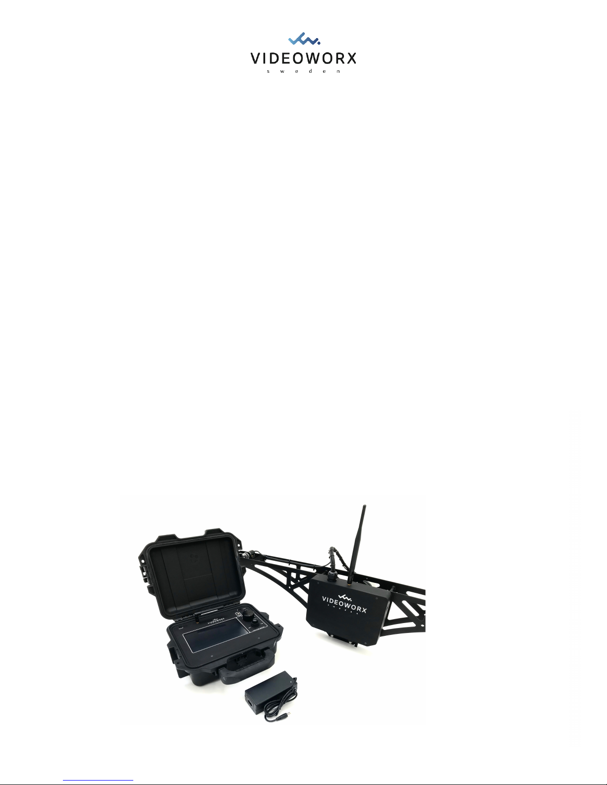
Streamline|2 Operating Manual
!
"
Introduction# 2!
Mode of Operation vs. Menu Page# 2!
Warranty# 2!
Maintenance# 2!
Description# 3!
Technical Specifications# 4!
Controller General# 5!
“CALIBRATE” Page# 6!
“NORMAL” Page# 8!
“CRUISE” Page# 10!
“POSITION” Page# 12!
“AUX” Page# 14!
“SETTINGS” Page# 15!
Messages# 16!
Rigging# 18!
Getting Started# 19
of 1 19
Version 1.0
Page 2
Introduction
Please take the time to read this page!!
Thank you for purchasing the Streamline|2 Cable Cam System. We have been working very hard
to make the system what it is today. We do appreciate any and all feedback in order to make the
system even better.!
CAUTION!!
Please be careful when operating the system and exercise good judgment when operating near
other people or property. The AUTO BRAKE FUNCTION has to be properly set-up to function
correctly and this responsibility rests with the operator. When operating with a cable at a steep
inclination or with a heavy payload, there may not be sufficient friction from the drive wheel to
bring the unit to a stop in time.!
In this manual the Streamline|2 Cable Cam will also be referred to as the “unit”. The front of the
Streamline|2 Cable Cam is the side with the “VIDEOWORX SWEDEN” logo.!
From this point on any text in the display menus or on display buttons will be written within
parenthesis, for example “BUTTON”.!
Mode of Operation vs. Menu Page
The NORMAL MODE is controlled with the settings on the “NORMAL” page. However, the
NORMAL MODE and the settings of the “NORMAL” page are aslo the active settings when
on any of the other menu pages as long as no other mode is activated.
For example if the “MAX SPEED” on the “NORMAL” page is set to 20 km/h, the max speed
will still be 20 km/h when the “CRUISE” page is selected, as long as the CRUISE MODE is
not activated.
Warranty
The Streamline|2 is covered by warranty for a period of 1 year from the date of purchase. The
warranty covers all faults from production. The warranty is void if the Streamline|2 or the
Streamline|2 Controller has been modified or opened.!
Maintenance
The Streamline|2 requires little or no maintenance. Keep it clean and regularly check that all
fasteners are secure. Avoid getting it wet, it will handle light rain but is not completely water proof.
If it gets wet, clean and dry before storage. Store in a dry environment.!
of 2 19
Version 1.0
Page 3

Description
The Streamline|2 Cable Cam System consists of the following components:!
Streamline|2 Cable Cam!
The Streamline|2 Cable Cam is an evolved and smarter version of the original Streamline Cable
Cam. All major components are machined from high grade aluminium. It incorporates a strong 3
hp brushed motor along with a speed controller that can handle currents up to 100A. The motor
and drive wheel assembly can easily be moved up or down to adjust the friction between the
drive wheel and the rope.!
Installing the Streamline|2 Cable Cam on the rope is done very quickly. The unit is installed from
on top of the rope and secured by attaching the base plate. With this design there is no way that
the unit can come off the rope unless it breaks. We also offer a Safety Wheel for a second rope as
an option.!
In order to keep track of position there is a rotary encoder connected to one of the carrier wheels.
This encoder along with another encoder located on the motor, allows for slip protection (Prevents
the drive wheel from slipping on the rope).!
The Streamline|2 Cable Cam uses the 2.4GHz band for two-way communication with the
controller and has a minimum range of 500 meters, line-of-sight. The controller transmit position
and speed commands and the Streamline|2 Cable Cam returns telemetry data regarding speed,
position, battery voltage, current etc.!
If the signal is lost or the controller is turned off, the Streamline|2 Cable Cam will return back to
the home position after a short delay.!
Streamline|2 Controller & Charger!
The Streamline|2 Controller is built into a rugged Pelicase. At the bottom of the Pelicase there is a
1/4” threaded hole that makes it easy to mount the controller on a regular tripod.!
The controllers primary interface is a 7 inch LED touch screen, that is used for selecting mode of
operation and making adjustments to settings. In addition some values may be adjusted using the
scroll wheel/push button.!
A combined Hall effect joystick/pushbutton is used to manually control the Streamline|2 Cable
Cam.!
An “ARM/STOP” toggle switch has complete authority over the Streamline|2 Cable Cam, causing
the motor to stop immediately when the switch is moved to the “STOP” position. This essentially
works as an emergency stop switch.!
The Streamline|2 Controller has an internal battery that lasts for a minimum of 3 hours. The
supplied charger can be used to charge the battery while the controller is being used.!
of 3 19
Version 1.0
Page 4

Technical Specifications
Streamline|2 Cable Cam!
•
Dimensions (L,W,H): 970x210x205mm!
•
Width 385mm with rods!
•
Weight: 3,3kg without battery!
•
Max Payload Tested: 15kg!
•
Speed Range: 0,5 - 50km/h!
•
Voltage Range: 12-25V (3-6S LiPo)!
•
Transmission Range: 500 meters!
•
Max distance: Depending on rigging fixtures!
•
Max Inclination (@ max payload): 10%!
•
Max cable diameter: 10mm!
Streamline|2 Controller & Charger!
•
Dimensions (L,W,H): 300x25x120mm!
•
Weight: XXXXXX!
•
Input Voltage: 12V !
•
Transmission Range: 500 meters!
•
Charger Input Voltage: 110V/230V (AC)!
of 4 19
Version 1.0
Page 5
Controller General
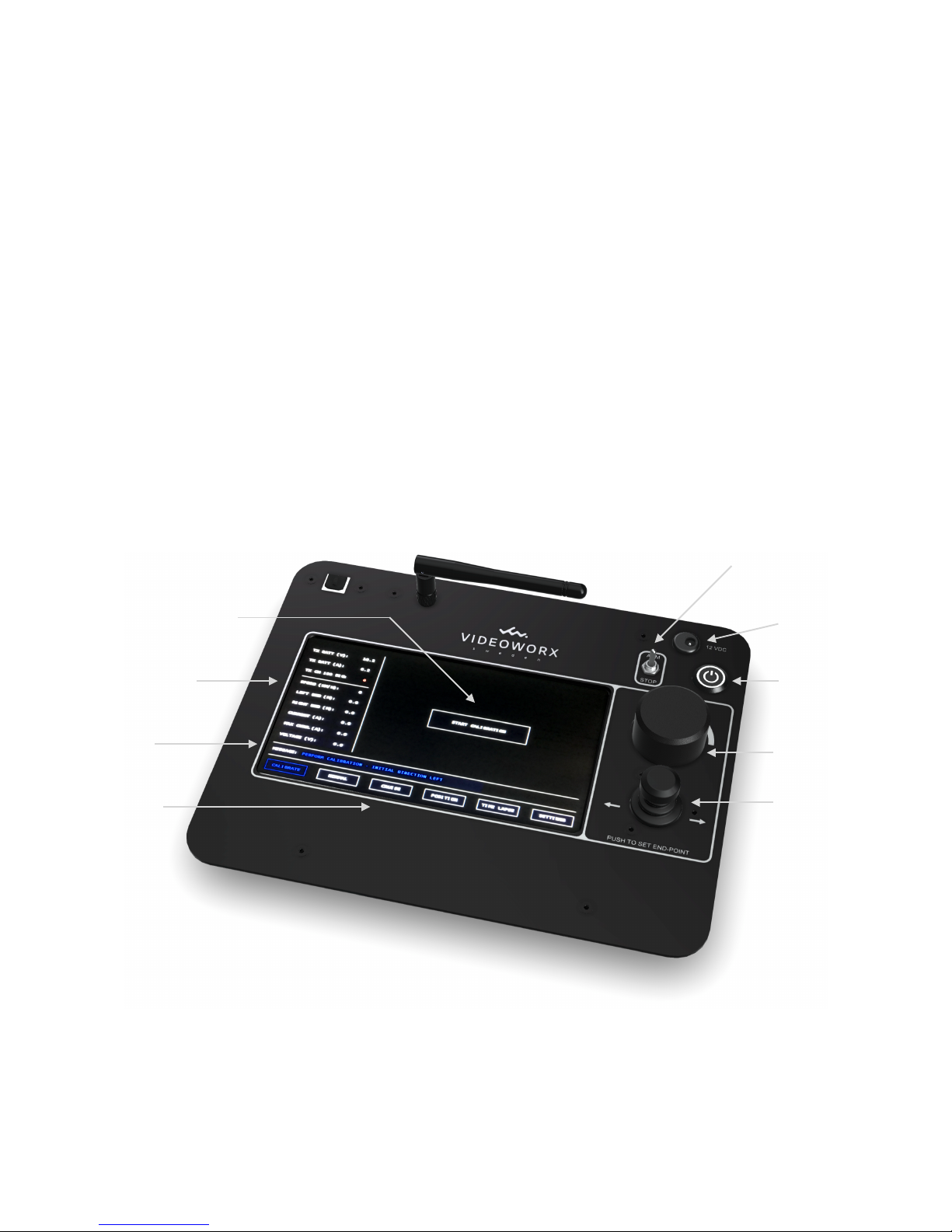
The 7” touch display is divided into four primary sections: !
1. Status and Telemetry Information !
2. Mode/Page specific Controls & Settings!
3. Messages!
4. Menu Page Selection!
Other controls & connections include:!
1. ON/OFF Switch !
2. ARM/STOP Switch!
3. Joystick/Push Button!
4. Scroll Wheel/Push Button!
5. Charger Connection!
!
of 5 19
Version 1.0
Charger !
Connection
ARM/STOP Switch
ON/OFF Switch
Scroll Wheel/!
Push Button
Joystick/!
Push Button
Status/Telemetry
Messages
Menu Page !
Selection
Mode/Page Specific!
Controls & Settings
Page 6
“CALIBRATE” Page
The controller defaults to the “CALIBRATE" page on start up. This is because the Streamline|2
requires a valid calibration before it can be operated.!
If a calibration has been performed and the Streamline|2 remains powered while the
controller is power cycled, the calibration will remain valid and the controller will proceed to
the NORMAL MODE.
Anytime the Streamline|2 has been powered off, a new calibration is required.
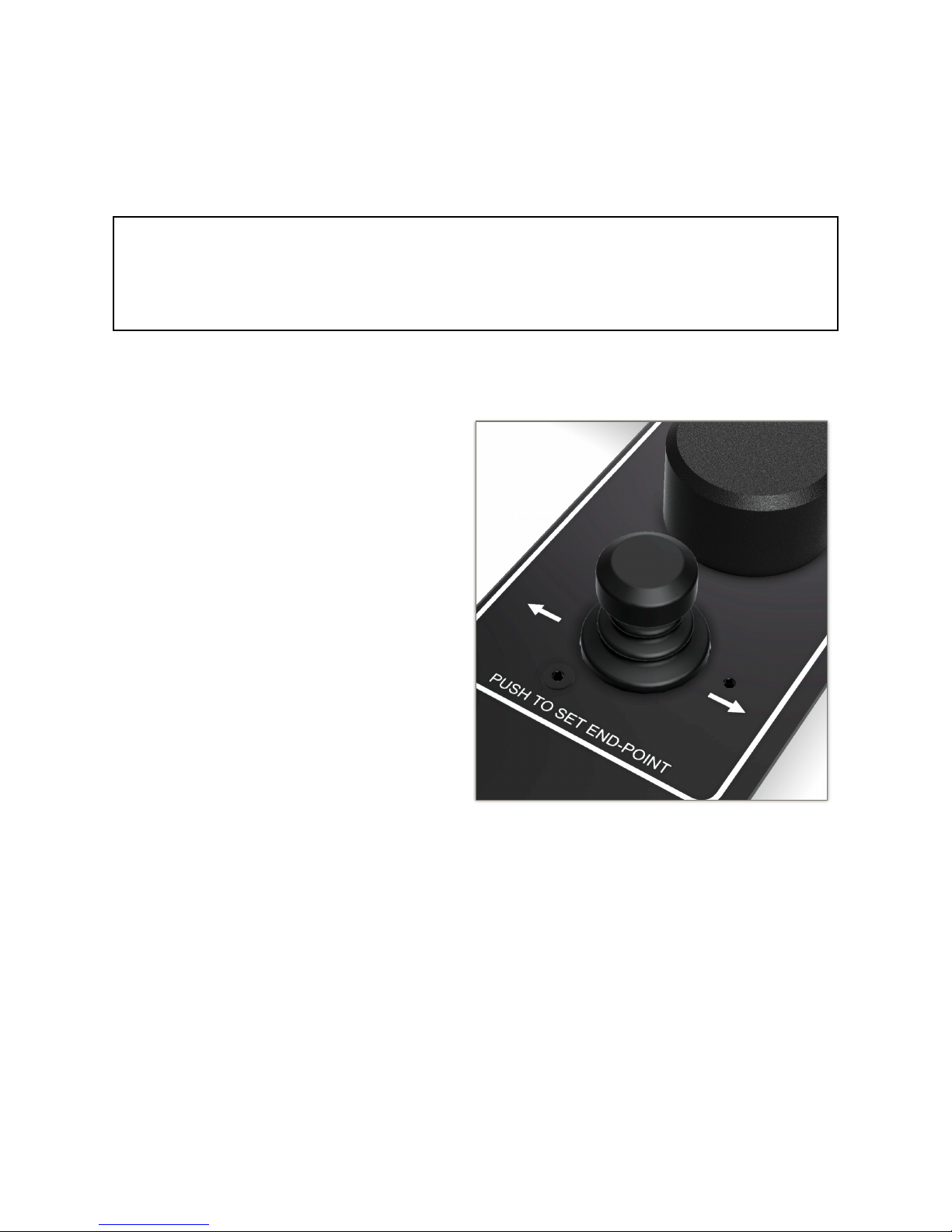
Calibration is initiated by pressing the “START CALIBRATION” button on the display.
The Streamline|2 will start moving to the
LEFT (as seen from the front of the unit) at
a speed of 3 km/h. The speed can be
increased up to 10 km/h by moving the
joystick to the left or decreased to a
complete stop by moving the joystick to
the right. If the joystick is returned to
neutral the unit will resume a speed of 3
km/h.
Once the Streamline|2 is at the desired left
end point, push down on the joystick
button to mark the position.
The Streamline|2 will immediately start
moving to the RIGHT at a speed of 3 km/h
(as seen from the front of the unit). The
speed can again be adjusted manually with
the joystick between 0-10 km/h. When the
joystick is in the neutral position the unit
will resume a speed of 3 km/h.
When the Streamline|2 reaches the desired right end point, again push down on the joystick
button to mark the position.
The calibration is now complete and the controller will automatically switch to the
“NORMAL” page.
of 6 19
Version 1.0
Page 7
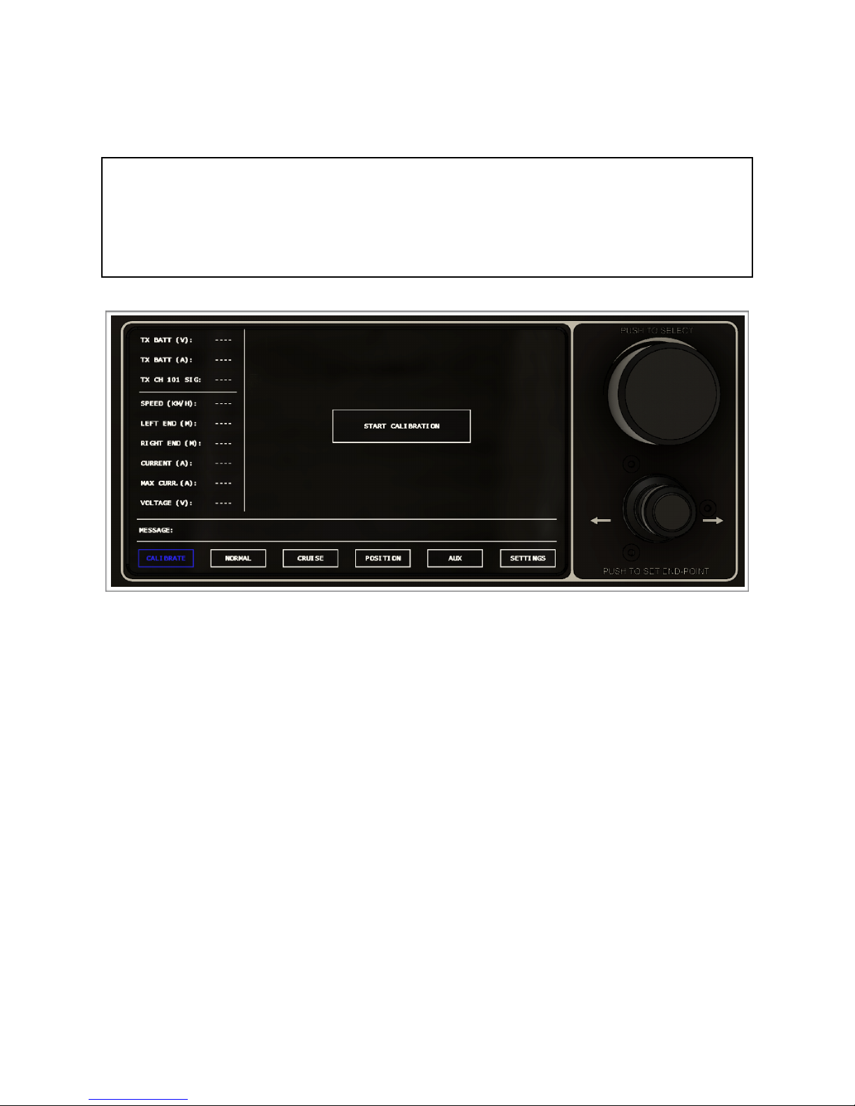
A new calibration can be performed at any time by returning to the “CALIBRATE” page, and
performing the above procedure again. When the unit has a valid calibration, the “START
CALIBRATION” button will instead read “RE-CALIBRATE”.
The position of the Streamline|2 when the “START CALIBRATION” button is pressed, is
saved as “HOME POSITION”. The unit will return to the “HOME POSITION” when:
•
The “HOME” button on the “POSITION” page is pressed.
•
60 seconds after signal loss.
•
When the on-board battery cell voltage drops below 3.2 Volts.
!
of 7 19
Version 1.0
Page 8
“NORMAL” Page
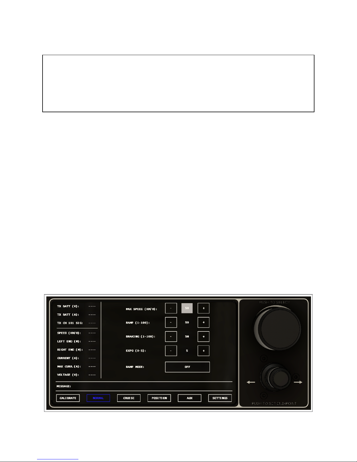
The NORMAL MODE is controlled with the settings on the “NORMAL” page. However, the
NORMAL MODE and the settings of the “NORMAL” page are aslo the active settings when
on any of the other menu pages as long as no other mode is activated.
For example if the “MAX SPEED” on the “NORMAL” page is set to 20 km/h, the max speed
will still be 20 km/h when the “CRUISE” page is selected, as long as the CRUISE MODE is
not activated.
When operating in NORMAL MODE, the Streamline|2 Cable Cam is manually controlled using the
joystick. If the joystick is returned to neutral the unit will stop.!
The “NORMAL” page allow you to adjust the following values using the “+” or “-“ buttons or by
using the scroll wheel:!
•
“MAX SPEED (KM/H)” - This value limits the top speed of the Streamline|2 Cable Cam. The
displayed range is from 0-50 km/h, however, the scroll wheel moves in increments of 0,5 km/h,
so the minimum speed that can be set is 0,5 km/h.!
•
“RAMP (1-100)” - This value determines how quickly the speed will ramp up or down. The
greater the value the faster the unit will be able to accelerate/decelerate.!
•
“BRAKING (1-100)” - This value determines at what point (depending on speed) prior to
reaching the end point that the unit will start braking. The higher the value the earlier the unit
will start braking. It is highly recommended to start at a high value and reduce only as
required.
•
“EXPO (1-5)” - This value can be used to reduce the joystick sensitivity around the neutral
position. A value of “1” makes the joystick linear and the most sensitive around neutral.!
of 8 19
Version 1.0
Page 9

“RAMP MODE” - This mode changes the control behaviour of the Streamline|2 Cable Cam.
Instead of controlling the speed, the joystick now controls ramp. By moving the joystick in
either direction, the unit will start accelerating in that direction proportionally to the control
input. When the joystick is returned to neutral, the ramp will be zero and the unit will
maintain it’s present speed. In short, set the desired direction and speed with the joystick
(increase or decrease speed at any time) and once let go, it will maintain it’s present speed.
The unit will still brake upon approaching the end point.
of 9 19
Version 1.0
Page 10
“CRUISE” Page
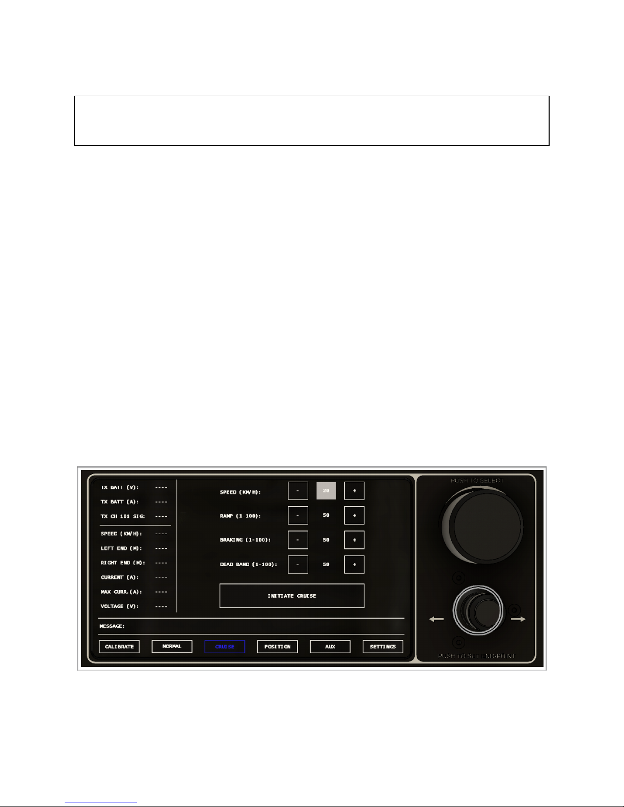
When the “CRUISE” page is selected, the Streamline|2 will still be operating in NORMAL
MODE until the “START CRUISE” button is pressed. This means that the parameters set on
the “NORMAL” page are active and manual control is available using the joystick.
The “CRUISE” page allow you to adjust the following values using the “+” or “-“ buttons or by
using the scroll wheel:!
•
“SPEED (KM/H)” - This value represents the requested cruise speed. The Streamline|2 will
accelerate to and maintain this speed. The displayed range is from 0-50 km/h, however, the
scroll wheel moves in increments of 0,5 km/h, so the minimum speed that can be set is 0,5 km/
h.!
•
“RAMP (1-100)” - This value determines how quickly the speed will ramp up or down. The
greater the value the faster the unit will be able to accelerate/decelerate.!
•
“BRAKING (1-100)” - This value determines at what point (depending on speed) prior to
reaching the end point that the unit will start braking. The higher the value the earlier the unit
will start braking. It is highly recommended to start at a high value and reduce only as
required.
•
“DEAD BAND (1-10)” - This value determines how close the unit needs to get to the end point
before it is allowed to start moving in the opposite direction. If there is a hesitation when the
unit is approaching the end point before moving in the opposite direction, try increasing this
value.!
of 10 19
Version 1.0
Page 11

Once the above settings have been adjusted as desired, press the “START CRUISE” button
to initiate CRUISE MODE. The Streamline|2 will start moving back and forth between the
two end points. The settings can be adjusted while the unit is operating in CRUISE MODE. It
is recommended to start with a high value for breaking and reduce gradually in order to
achieve smooth and timely breaking. The CRUISE MODE can be stopped at any time by
pushing the “STOP CRUISE” button. The unit will then resume NORMAL MODE.
Placing the ARM/STOP toggle switch to “STOP” will also stop the Streamline|2 during
CRUISE MODE. When the toggle switch is placed back in the “ARM” position, the
Streamline|2 will resume CRUISE MODE.
of 11 19
Version 1.0
Page 12
“POSITION” Page
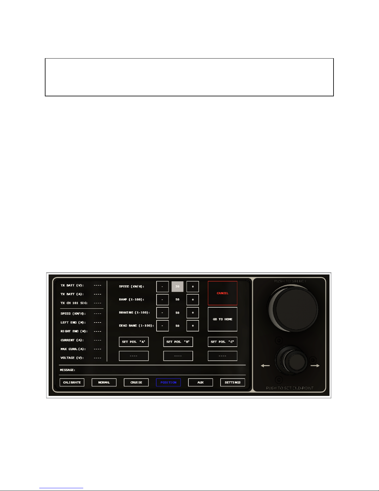
When the “POSITION” page is selected, the Streamline|2 will still be operating in NORMAL
MODE until one of the “GOTO A/B/C/HOME” buttons are pressed. This means that the
parameters set on the “NORMAL” page are active and manual control is available using the
joystick.
The “POSITION” page allow you to adjust the following values using the “+” or “-“ buttons or by
using the scroll wheel:!
•
“SPEED (KM/H)” - This value represents the requested speed when moving to position “A/B/
C”. The Streamline|2 will accelerate to and maintain this speed. The displayed range is from
0-50 km/h, however, the scroll wheel moves in increments of 0,5 km/h, so the minimum speed
that can be set is 0,5 km/h.!
•
“RAMP (1-100)” - This value determines how quickly the speed will ramp up or down. The
greater the value the faster the unit will be able to accelerate/decelerate.!
•
“BRAKING (1-100)” - This value determines at what point (depending on speed) prior to
reaching the position “A/B/C” that the unit will start braking. The higher the value the earlier the
unit will start braking.
•
“DEAD BAND (1-100)” - This value determines how close the unit needs to get to the position
“A/B/C” before considering the move complete. If there is a hesitation when the unit is
approaching the position “A/B/C” before coming to a complete stop, try increasing this value.!
!
In order to set a position, manually move the Streamline|2 to the desired position using the
joystick. In order to set position “A”, press the “SET POS “A” button. The button will now
indicate the selected position by displaying the distance in meters from the left end point.
The selected position can be changed at any time by pressing the same button again. The
procedure for setting position “B” and “C” is the same.
of 12 19
Version 1.0
Page 13

Once position “A” has been set, press the “GOTO A” button to initiate POSITION MODE.
The Streamline|2 will now move to the requested position using the settings above. The
move can be cancelled at any time by pressing the “CANCEL” button. When the move is
complete or the “CANEL” button has been pressed, the unit will resume NORMAL MODE.
of 13 19
Version 1.0
Page 14

“AUX” Page
Intentionally left blank.!
of 14 19
Version 1.0
Page 15
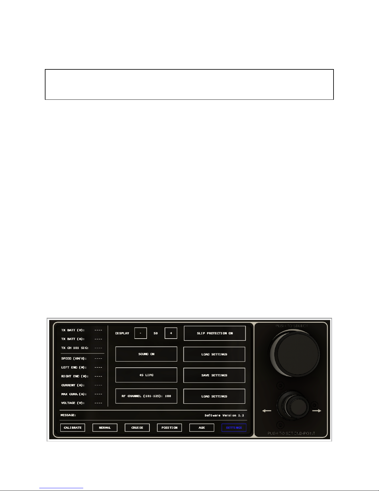
“SETTINGS” Page
When the “SETTINGS” page is selected, the Streamline|2 will still be operating in NORMAL
MODE. This means that the parameters set on the “NORMAL” page are active and manual
control is available using the joystick.
The “SETTINGS” page allow you to adjust the following values using the “+” or “-“ buttons, or by
pressing the button to sequence to the next value:!
•
“DISPLAY” - Display brightness value ranging from 5% to 100%.!
•
“SOUND ON/OFF” - Selecting “SOUND OFF” inhibits the sound when pressing a button.!
•
NUMBER OF CELLS (4S - 6S) - This value is used to determine the minimum allowable
voltage of the on-board battery.!
•
“RF CHANNEL (101-125)” - Allows section of an alternate frequency incase of poor reception.!
•
“SLIP PROTECTION ON/OFF” - Selecting to “OFF” inhibits slip protection.!
•
“SAVE SETTINGS” - Saves all current settings/parameters.!
•
“LOAD SETTINGS” - Loads previously saved settings.!
•
“DEFAULT SETTINGS” - Loads the default settings.!
!
of 15 19
Version 1.0
Page 16

Messages
The following is a description of the messages that may be posted on the controller:!
•
"STREAMLINE BATTERY DEPLETED - RETURNING TO HOME” - Based on the number of
cells selected in the SETTINGS PAGE, when the cell voltage reaches 3.2 Volts, the Streamline|2
will return to the HOME position. This is a precaution to avoid running out of power and leaving
the unit in a position were it cannot be reached. When this message is displayed the unit will
return to home and become unresponsive until a cell voltage of 3.8 or greater is detected.!
•
"STREAMLINE BATTERY LOW - LESS THAN 3.5 VOLTS/CELL” - This message informs the
operator that the battery voltage is getting low - less than 3.5 Volts/cell.!
•
"RESET EMERGENCY-STOP TO RESUME” - This message is displayed any time the ARM/
STOP toggle switch is in the “STOP” position.!
•
“SLIPPING” - This message is displayed when Streamline|2 detects that the drive wheel is
slipping. When this occurs, the motor will only turn the drive wheel at small increments to see if
the slipping has been resolved. This is safety function that prevents the drive wheel from
spinning on the rope if the unit is stuck.!
•
"NO MESSAGES” - The controller has no other messages to display.!
•
"PERFORM CALIBRATION - INITIAL DIRECTION LEFT” - This messages is displayed when the
controller is powered ON and no valid calibration is present. Proceed with normal calibration.!
•
"MOVING LEFT - PUSH TO STOP” - This messages is shown after the “START
CALIBRATION” button has been pressed and the Streamline|2 is moving towards the left end
point.!
•
"MOVING RIGHT - PUSH TO STOP” - This messages is shown during calibration when the
Streamline|2 is moving towards the right end point.!
•
"CALIBRATION COMPLETE” - Calibration is complete.!
•
"PREVIOUS CALIBRATION STILL VALID” - This message will be displayed if the controller
was turned OFF or lost power while the Streamline|2 remained powered with a valid calibration.
A new calibration should not be required.!
•
"STREAMLINE LOST POWER - PERFORM NEW CALIBRATION” - The messages is displayed
if the Streamline|2 was turned OFF or lost power while the controller remained ON. A new
calibration will be required.!
•
"SETTINGS SAVED” - This message is displayed when the “SAVE SETTINGS” button on the
SETTINGS page is pressed to indicate that the current settings have been saved.!
of 16 19
Version 1.0
Page 17

MESSAGES (Continued)!
•
"SETTINGS LOADED” - This message is displayed when the “LOAD SETTINGS” button on the
SETTINGS page is pressed to indicate that the current settings have been loaded.!
•
"CRUISE LEFT” - This message is displayed in CRUISE MODE when the Streamline|2 is
moving left.!
•
"CRUISE RIGHT” - This message is displayed in CRUISE MODE when the Streamline|2 is
moving right.!
•
"POSITION RECORDED” - This message is displayed when a new position has been recorded
on the POSITIONS page.!
•
"MOVING TO POSITION” - This message is displayed when the Streamline|2 is moving to the
selected position in POSITION MODE.!
•
"MOVE TO POSITION COMPLETE” - This message is displayed when the Streamline|2 has
completed moving to the selected position in POSITION MODE.!
•
"UNABLE - POSITION NOT SET” - This message is displayed when on the POSITION page
and one of the “GOTO A/B/C” buttons are pressed without having a previously saved position.!
•
"CANCELED GO TO POSITION” - This message is displayed when the Streamline|2 is moving
to the selected position in POSITION MODE and the “CANCLE” button is pressed.!
of 17 19
Version 1.0
Page 18

Rigging
Equipment!
Make sure to use equipment that is rated to handle the forces that it will be subjected to. This also
applies to the fixtures or attachment points. The Streamline|2 can be used with ropes 10mm or
less. It is recommended to use Dyneema rope or rope with a Dyneema core as these have a very
low elasticity. We offer a range of suitable rigging equipment including rope, slings, hand winches,
powered winches, dynamometers, Portawraps and more. Please visit our website or contact us
for more information.!
Fixtures!
It is recommended to use a dynamometer or similar to determine the forces induced on the
fixtures (and equipment) if there is any uncertainty. Use high quality slings or similar to connect
the rope to the fixture.!
Rope Tension!
As a rule of thumb, with the Streamline|2 at the mid point, the rope should slack about 1 meter for
every 50 meters of rope. The theoretical forces can be calculated using online zip-line calculators,
however, if possible use a dynamometer or a crane scale to get the actual values.!
The Portawrap is a useful tool that makes it easy to manually tensions the rope before using a
winch. It also minimises any chances of damaging the rope as it require no knots.!
Once there rope has been manually tensioned, use a winch to properly tension the rope as
required.!
Safety Rope!
If using a second rope for added safety along with our optional wheel assembly, install the second
rope 15-25cm above the primary rope. Use the same procedure for tensioning this rope. !
Using a second rope is also advantageous when operating with heavy payloads as it reduces the
load on the primary rope.!
of 18 19
Version 1.0
Page 19

Getting Started
1. Start by removing the two M4X70mm bolts that hold the base plate in place.!
2. Lower the Streamline|2 onto the rope from the top. It the rope is tight is easiest to put the rope
over the drive wheel before placing the rope under the carrier wheels.!
3. Re-install the base plate using the two M4x70 bolts. !
4. Check the friction between the drive wheel and the rope. If there to much friction, the
motor and batteries will be subjected to unnecessary load which will result in higher
than normal operating temperatures. If there is not enough friction, the drive wheel will
slip on the rope. Adjustment is done by slightly unscrewing the four hex screws that
hold the motor in place and sliding the motor up/down as desired.
5. Install gimbal and camera equipment.!
6. Turn on the Streamline|2 controller.!
7. Connect the battery to the Streamline|2 Cable Cam.!
8. Wait briefly and then confirm that all the telemetry values are acceptable.!
9. Initiate calibration by pressing the “START CALIBRATION” button on the controller. The unit
will now start moving slowly to the left. Be ready to press down on the joystick button when
the unit is at the desired end point. It is recommended to set the end point at least 1-2 meters
from the end of the rope to have some additional margin of error.!
10. Once the left end point has been selected, the Streamline|2 will start moving to the right.
Again, be ready to press the joystick button when the unit is at the desired end point.!
11. The calibration is now complete and the controller should automatically transition to the
“NORMAL” page.!
12. At this time we can adjust the settings for max speed, ramp and braking. It is recommended
to start with a high value for braking and reduce only as required.!
13. The Streamline|2 is now ready to use - enjoy, and let us now how you like it!!
of 19 19
Version 1.0
 Loading...