

VideoWave n-E4E User Manual

U
U
U
s
s
s
e
e
e
r
r
r
’
’
’
s
s
s
m
m
m
a
a
a
n
n
n
u
u
u
a
a
a
l
l
l
Digital Video Recorder
VViiddeeooWWaavvee NNeettwwoorrkkss IInncc..
7493 Trans-Canada highway #103, St-Laurent (Quebec) H4T 1T3
Tel.: 514-668-1845 Fax: 514-789-0878
www.videowave.ca
info@videowave.ca

Before you begin…
========================================== = = = = = = = = = = = = = = = = = =
This documentation explains the configuration of the DVR system (‘system’) and its program, and how to
use them.
Please read this user guide before you use the system.
Check each component when you unpack the package, and contact the supplier if you have any question.
Safety Notice (Please Note)
========================================== = = = = = = = = = = = = =
1. Notes before installing the product
Take out the components and place them on a dry and flat floor. The rear part of the system must
be 15cm from the wall.
Install in a well ventilated place.
It is inappropriate to install the system in a place where electromagnetic waves and strong
magnetism are generated (e.g. near speaker, etc.)
It is inappropriate to install the system under a direct ray of light or near the thermal equipment
such as a heater in order to protect the system.
It is inappropriate to install the system in a cold place exposed to outside.
Be careful not to damage the system by other tools or equipments in the work area..
It is inappropriate to install the system in a severely shaking or humid place.
Please check the voltage you use before connecting the power cord. (This system is produced to
be used with 220V. To use the system in an area where 110V is supplied, adjust the conversion
switch of the power section in rear of the system.)
Connect the power cord.
After you have taken out the components, dispose the plastic wrapper (Keep it out of reach of
children. It is very dangerous for a child to wear it on his/her head.)
2

2. Notes on using the product
Please contact the supplier if the product does not function. If you personally dismantle the
product to fix it, you may not receive the maintenance service.
Please make sure to read the user guide before using the product.
When dismantling or repairing the product inevitably, please carefully handle it since the
components are very sensitive.
For your safety, do not touch the power cord or outlet with wet hands.
Please be careful to correctly plug in the power cord to an outlet.
Do not clean the product with a substance containing alcohol like thinner and benzene.
Do not touch the exposed terminal, if possible.
Before you shutting off the system power, end all programs and its related auxiliary programs.
(If the system does not shut off, use the Power button in front of the system.
Operate the system near the magnetic body or in a well ventilated area.
Do not dismantle or repair the system at discretion.
Do not place any heavy item on the system.
Do not move the system while operating the system.
If smoke coils from the main body or it smells strangely, immediately turn off the power and
contact the supplier for the technical assistance and maintenance.
Guarantee
========================================== = = = = = = = = = = = = = = = = =
If the system does not function properly, we replace the components or system. The guarantee period can
be extended by a separate agreement. Please ask your supplier for more information.
Conditions of maintenance
========================================== = = = = = = = = = = = = = = = = =
If the system malfunctions within 1 year from the purchase date, we replace the components or system
free of charge (Please understand that free replacement service is not available if the system fails due to
user’s careless operation or a natural disaster.)
3

Free maintenance or replacement service is not applicable if:
1. The system was stopped due to a user’ fault.
2. The user did not follow the instructions in the user guide in using the system.
3. The rated voltage and frequency specified in the user guide were not used.
4. Replacing consumables or cleaning the system.
5. The system failure occurred after an unauthorized person who did not complete the required
training course dismantled the system.
After the free maintenance period is expired, you can have your system upgraded or repaired at minimum
expense. Should you require these services, please ask your supplier for more information.
Product Name
Product Number
Supplier / Telephone
Date of Purchase
Guarantee Period
Name
Customer
Address
Information
Telephone
We do not issue the information above on the product purchase.
Please understand the details and conditions from the supplier when you make purchase.
You should show the information above when requesting a maintenance service.
4

INDEX
. System Component
. Introduction
1. System Features
2. Major Functions
III. How to Use and System Functions
1. Monitoring Screen (Default Screen)
2. Environment Setup (System Setup)
2-1. System Setup
2-2. Resolution & Audio Setup
2-3. Camera Setup
2-4. Recording Schedule Setup
2-5. Network I
2-6. Network II
2-7. Sensor & Relay
2-8. User Setup
2-9. System Information
3. Search Function
4. Backup
4-1. Manual Backup
4-2. Schedule Backup
4-3. Manual Backup Viewer
4-4. Automatic Backup Viewer
5. Image Analysis
6. Log Viewer
7. Hardware and Connection Configuration
5

. System Component
Take out the components in a flat and dry area, and then check if the following components are all
included.
Components of DVR Set
========================================== = = = = = = = = = = = = = = = = = =
⊠ DVR Main Body
⊠ Power Cable
⊠ User Guide
⊠ Program CD
⊠ OS Laved (Windows 98 or Higher Version)
⊠ Keyboard & Mouse
⊠ Subcomponents of Each Model
Components of DVR Kit
========================================== = = = = = = = = = = = = = = = = = =
⊠ Program CD (DVR, RDVR, Driver)
⊠ Capture Board or Video Board
⊠ Camera Input Cable
⊠ Subcomponents of Each Model
6

7

. Introduction
What is the DVR?
========================================== = = = = = = = = = = = = = = = = = =
This system digitalizes and stores the analog video and voices on a storage device, and allows users
to search by any criteria they specify and to transmit the image through a network. This is commonly
known as the DVR(Digital Video Recorder).
1. System Features
========================================== = = = = = = = = = = = = = = = = = =
1) Stabilized System
This system has been stabilized and verified by six years of research and development.
2) Efficient File System
The system stores data on baskets which are the disk space partitioned into certain areas. This file
system efficiently aligns data and maximizes the speed of data processing. In addition, the stored
data is effectively protected.
3) Outstanding Image Quality and Search Methods
The system provides various search conditions and an excellent image quality for searching an event
or constantly saved data.
4) Convenient User Interface
The system allows users to operate it with simple mouse operation in a GUI environment for
convenience.
5) Various Network Functions
The system provides the remote monitoring, recording, searching, sending, and controlling functions
as well as the two-way voice communication through a network in real time. The transmission can
also be enabled using a telephone modem and diverse networks.
2. Major Functions
========================================== = = = = = = = = = = = = = = = = = =
Maximum 16 real time images can be monitored.
30 ~ 480 frames can be recorded, and the system is equipped with an efficient MPEG4
coder/decoder.
Each camera can be operated with different compressing methods and recording speeds.
The system uses the same method used to save file systems and provides a stable recovery
function for file systems.
The system provides the remote monitoring (LAN, PSTN, ISDN), Single & Multi RDVR, two-
way voice communication functions.
The saved data can be backed up using searching and various backup devices (DAT, DVD, ADR,
DLT, CD-RW, On-Stream).
Various searching methods: Event search, motion search, panorama search, search by minute, jog
shuttle search, and search by camera combination
System monitoring function (Watch Dog)
Remote notification function ( PDA, email, text transmission )
Audio recording function
The system distinguishes the function for each user and provides him/her appropriate account and
password ( Multi-Level Password )
Various type of alarms (beep sound, moving line, enlarged screen, and email)
8
Remember Before You Start !!!
⊠ G.U.I (Graphic User Interface) : An operating environment designed to allow users to
use a function by clicking or double-clicking it with a mouse on a screen. This system
operates in a GUI environment.
⊠ If you move the mouse pointer to an icon, the description on its function automatically
activates.
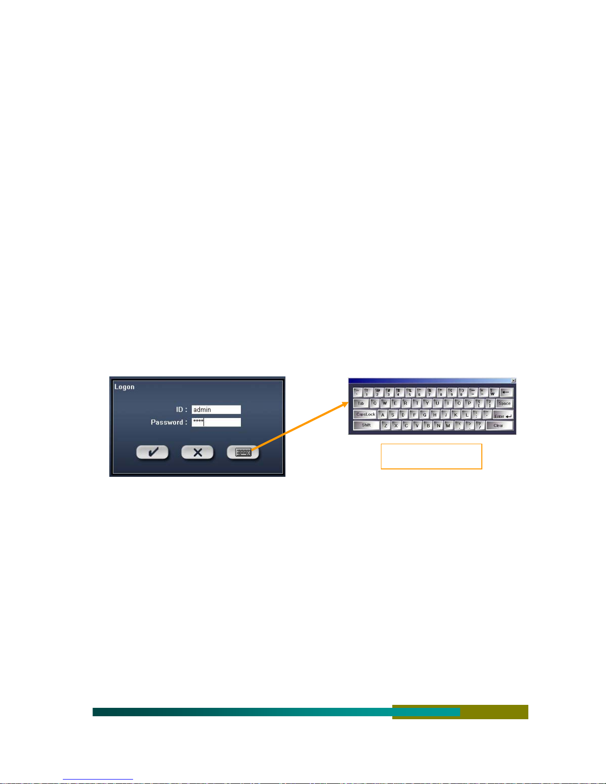
⊠ In order to use all functions upon starting the system, first release the key lock (user
authorization) and enter the account and password.
⊠ Default setup value < account : admin / password : 1111 >
(For the system security, it is recommended to change the account and password after
the user authorization.)
⊠ The watch-dog function which operates automatically at system failure has not been
configured to operate at system startup. Check the watch-dog column in the
environment setup when you start the system.
⊠ If you operate the system without camera input images at initial startup, the beep may
sound. It is an alarm due to disconnection of images, and not a system failure.
Virtual Keyboard
⊠ For the system security, lock the key after using the system.
9

⊠ If you connect the power after an abnormal termination, an “analyzing the file system”
message window appears for system stabilization.
⊠ User guide common to all the models including the capture, live, 4ch, 9ch, and 16ch
(unsupported menus are not activated).
10
III. How to Use and System Functions
1. Monitoring Screen (Default Screen)
========================================== = = = = = = = = = = = = =
⊠ When power is connected to the system, the following monitoring screen appears after the system
booting process.
1
1 [M] OFFICE 1 [P][A]
3 [C] OFFICE 2
2 [M] PARKING LOT [P]
4 [C] ATM [A]
3
4
5
2
END
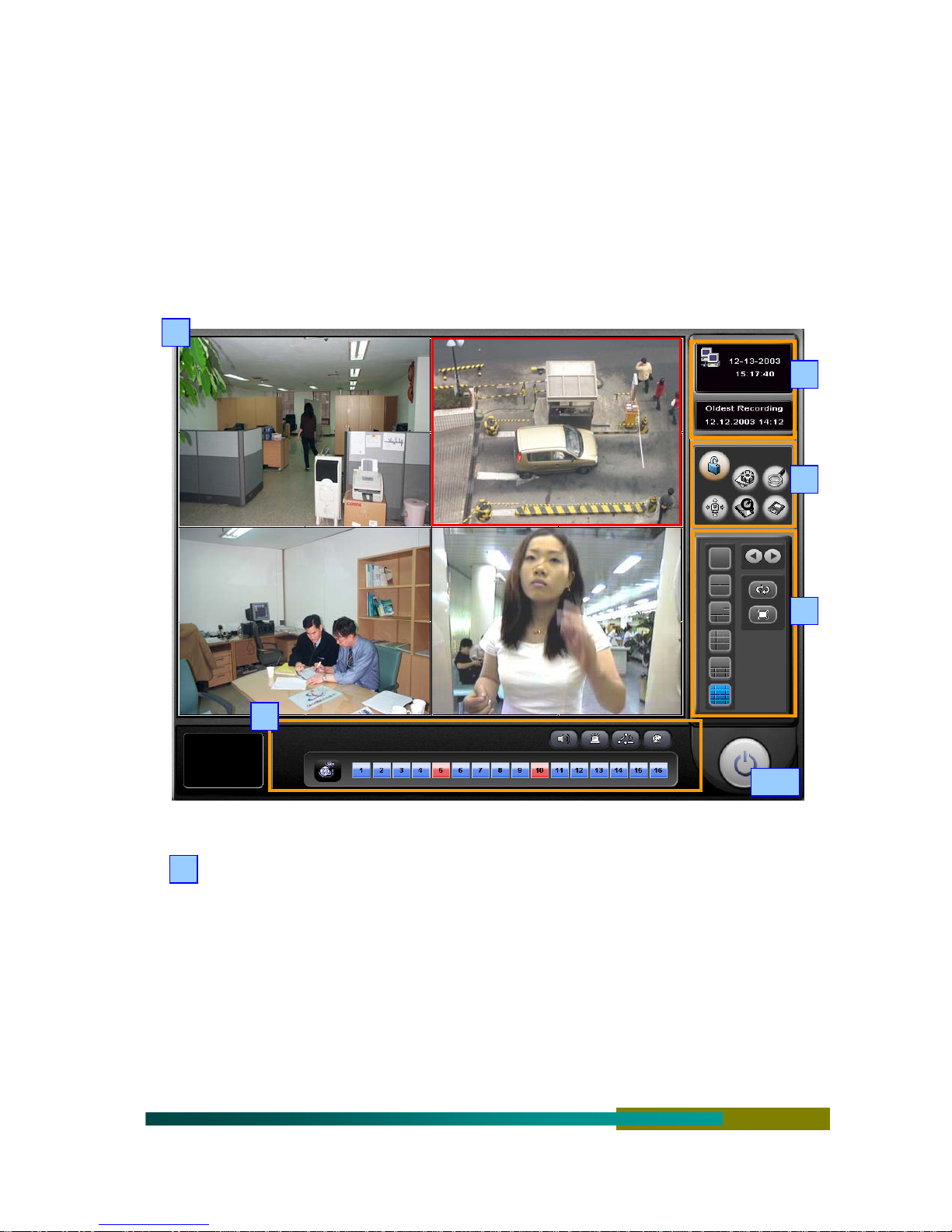
Monitoring Screen : Shows the camera image and camera connection information.
1
[Camera Information]
Camera Number : Displays the camera input number
Recording Condition : Displays [N]Do not record, [C]Constantly, [M]Moving, [S]Sensor,
[C&E]Constantly & Event [S&M]Sensor & Moving
Camera Name : Displays the configured camera name
PanTilt Connection : Displays [P] if the PanTilt is connected
Audio Connection : Displays [A] if the audio is connected
Red Outline : Displays the red outline around the image if there is an event in a camera
11

2
Screen Split : Use to configure the screen.
[ Screen Split ]
: Does not split the screen (manually or automatically converses the screen to a full
screen)
: Splits the screen into 4 sections (manually or automatically splits the screen into 4
sections or restores it.)
: Splits the screen into 6 sections (manually or automatically splits the screen into 6
sections or restores it.)
: Splits the screen into 9 sections (manually or automatically splits the screen into 9
sections or restores it.)
: Splits the screen into 10 sections (manually or automatically splits the screen into
10 sections or restores it.)
: Splits the screen into 16 sections.
[ Screen Conversion ]
: Manually reverses the screen
: Manually forwards the screen
: Automatically converses the screens (specify the time for conversion in the setup
– maximum 10 seconds)
: Fully enlarges the screen (double click the left mouse button in the monitoring
screen to “enlarge”, or click the right mouse button to “reset” )
Status Display Window : Connection of cameras and audios, channel selection, sensor input
3
verification, relay control, image quality adjustment
[ Camera Status ]
Blue : Normal,
Red : Disconnection of cameras, # Grey : Camera not used
[ Audio Connection Status ]
< Click a corresponding channel => listen to the current audio >
Light Green : Selected channel (currently played audio)
12
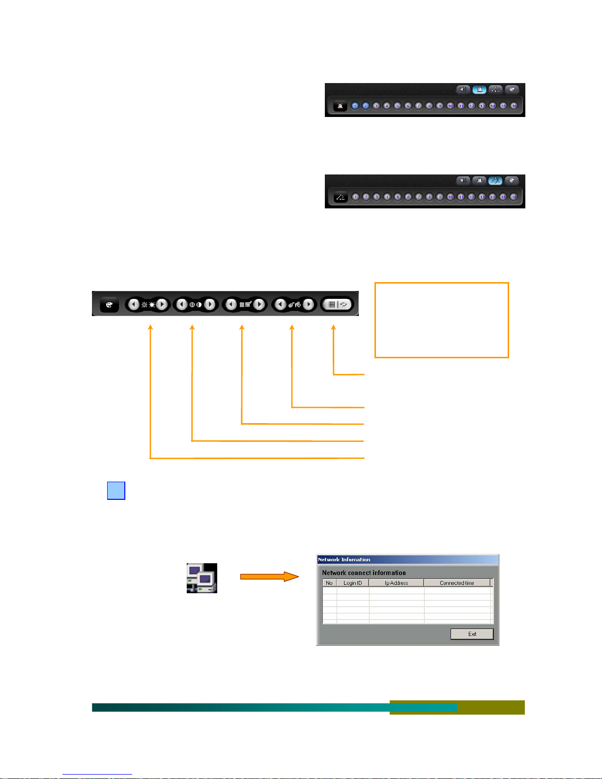
Light Grey : Currently used audio channels, # Grey : Audio not used
[ Sensor Input Verification ]
Purple : Sensor input is enabled
Grey : Signal is ready or not used
[ Relay Control ]
< Click a corresponding channel => display the relay >
Yellow : Relay is operating
Grey : Relay is ready or not used
[ Image Quality Adjustment ] < Click a camera before adjusting the image quality >
< lower left corner >
Adjusted value automatically
activates
Brightness 2
Apply the adjustment value to all or
apply the default value
Hue adjustment
Saturation adjustment
Contrast adjustment
Brightness adjustment
4
Index Information Window : Shows the current date, time, hard disk saving status, and network
access information.
Network Access Information : Shows the ID and IP of a user access from a remote site.
“Double Click the Icon”
( Note : The system allows maximum 5 direct accesses to DVR through network at a time)
Oldest Record Date
13
Function Buttons : Key Lock, Environment Setup, Search, Rotational Camera, Fast Search,
5
Backup (Refer to each section for more information)
Key Lock : Used for security purpose. (Requires an user authorization to release)
< Default Account >
admin
< Default Password >
Virtual Keyboard
1111
(It is recommended to change the account and password after user authorization for the security purpose)
Environment Setup : Configures the system
Search : Searches recorded image or audio
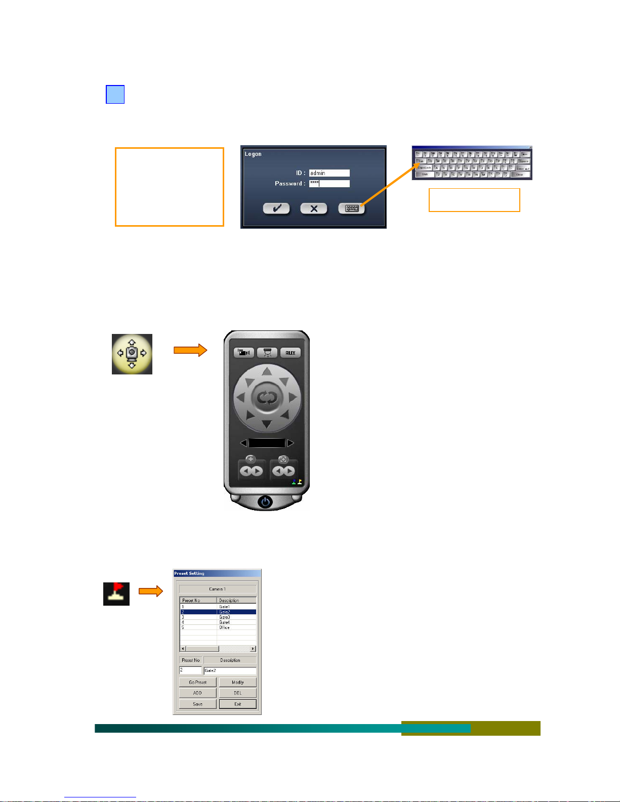
PanTilt control : Click the PanTilt button to activate the control window as shown below (the
control window can be moved with the mouse)
Turns on/off the camera power
Turns on/off the light power
Turns on/off the AUX power
Rotates to the direction specified
Turns on/off the auto pan
Specifies a camera (moves to the left or right)
Zoom in (left), zoom out (right)
Focus near (left), focus far (right)
Configures the preset and moves
Configures the touring and moves
9 Position the pointer to a button to activate a description window.
9 Some functions may not be supported depending on the type of receiver or speed dome camera used.
[ How to Setup the Preset ]
14
Click the button to activate the left window
Move to the location of camera to specify
Enter the preset number and description, and press the add
button
Add preset numbers using the same method (maximum 64)
To execute the preset : Press the move button after specifying the
number
To edit the preset : Specify the relevant number, move to the
camera and click the edit button.
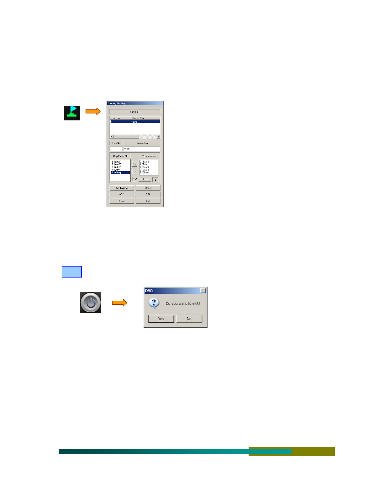
[ How to Setup the Touring ]
Save the operation before closing.
Fast Search : Searches an image and checks the content of an event with event signals
Back Up : Executes a manual backup
To delete the preset : Specify the relevant number and click the
delete button
Click the save button before closing.
Click the button to activate the window shown in the left.
Enter the touring list using the preset number
Enter the touring number and its description, and configure DW
(delay time)
Complete by clicking the add button
Enter the touring list using the same method (maximum 12)
To execute the touring : Specify a number and click the move
button
To edit the touring : Specify the number, reenter the touring list,
and click the edit button
To delete the touring : Specify the number and click the delete
button
END
The button to end the program
Click the “Exit” button.
A window appears to confirm.
Click “Yes” or “No.”
15
2. Environment Setup ( System Setup )
========================================== = = = = = = = = = = = = =
⊠ The environment setup is used to configure the system operation including functions to use and the
time to operate the system to meet the requirements of users.
⊠ Please note the following information.
√ The setup menu consists of 9 tabs. When you finish operation for each tab, click the
“Apply” button before moving to the next tab.
√ If the system detects a failure, the watch-dog function reboots the system in specified period of
time with the beep. The system is not configured with this function in the warehouse. Check the
watch-dog setup column to use this function.
√ If the beep is configured by interworking with event signals which is different from the watch-
dog function, the beep may be generated. For your reference, the system generates the beep
when the camera signal is disconnected.
√ Some functions automatically reboots the system when selected. These are available only after
the system rebooted.
√ Only four cameras are configured to constantly record the images in the warehouse. Setup the
schedule, and the condition to record and use cameras as required by the field.
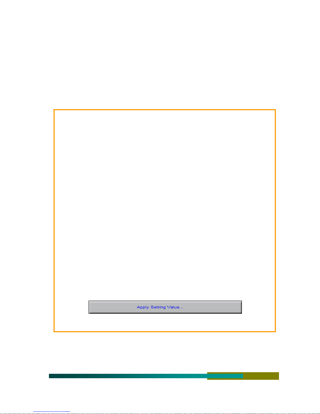
√ Click the “Apply” button after configuring each tab and click “OK” to complete the setup
process. Then, following window appears in the monitoring screen and the screen starts to
blink within approximately 5 seconds while initializing the hardware and software.
16
2-1. System Setup
========================================== = = = = = = = = = = = = =
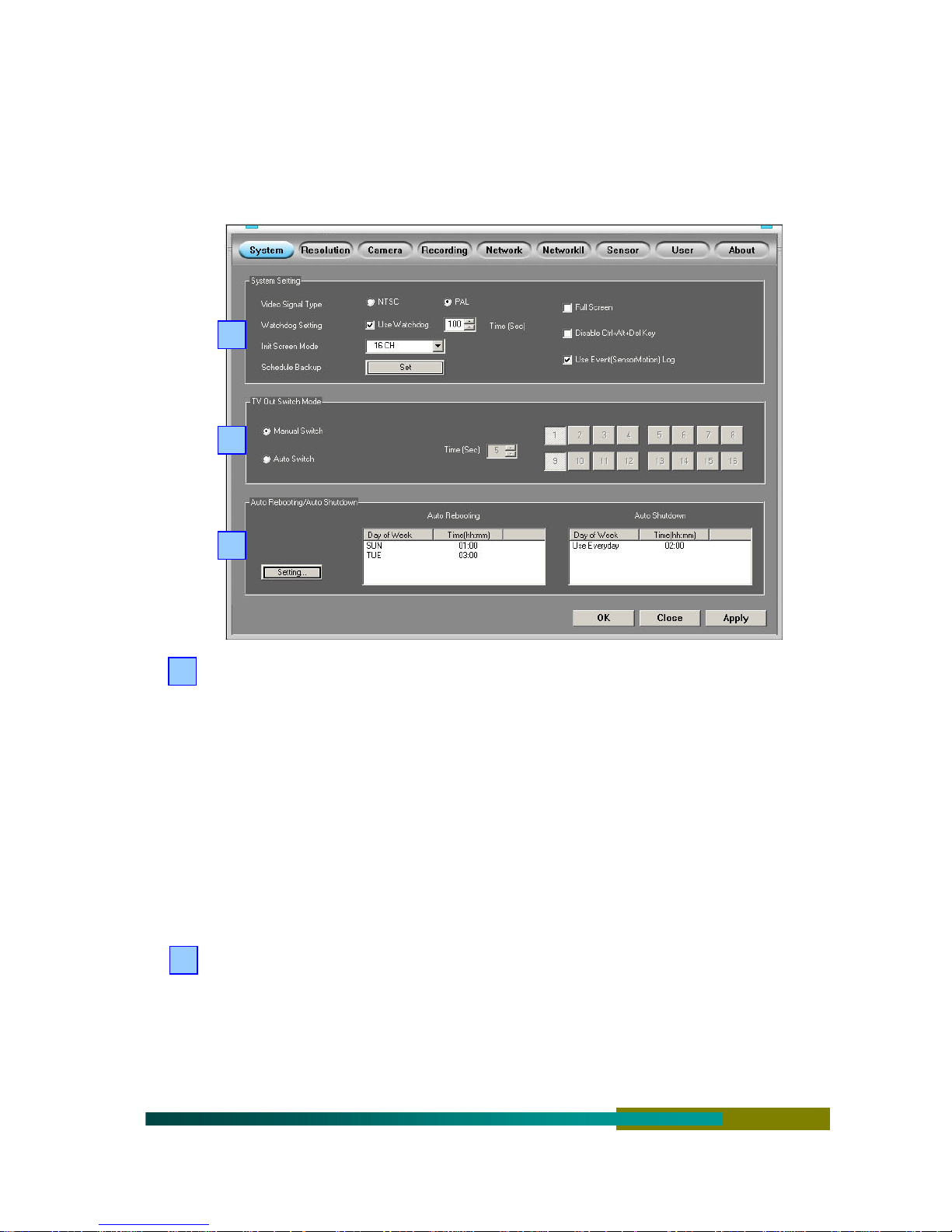
⊠ Click the “System” tab to open the setup window as below.
1
2
3
System Setup : Configures general system specifications.
1
Camera Type : Select the NTSC or PAL
Watchdog Setup : Select to enable this function and select the delay time (more than 100
seconds is recommended)
Default Screen Setup : Select the default split screen after booting or environment setup
Backup Setup : Click the “Setup” tab to activate the window for schedule backup setup.
(Explained in more detail in the relevant section)
Full screen : Select to apply the full screen by default after booting or environment setup
Disable Ctrl+Alt+Del : Select to prevent forced termination and booting.
Enable Event Search : Select to enable the event search in the monitoring screen
2
TV Out Conversion Mode : Configures external monitor (TV) display
Manual Conversion : Displays only the camera images specified in the monitoring window to
a TV (applies in the same way when specifying the PanTilt numbers)
Automatic Conversion : Only selected camera images are automatically conversed after
specified time.
(The cameras must be specified after selecting the automatic conversion to display the images to a TV)
17
Manual and automatic conversion TV out are supported for the capture model only.
Automatic System Restart / Automatic System Termination : Specifies the schedule.
3
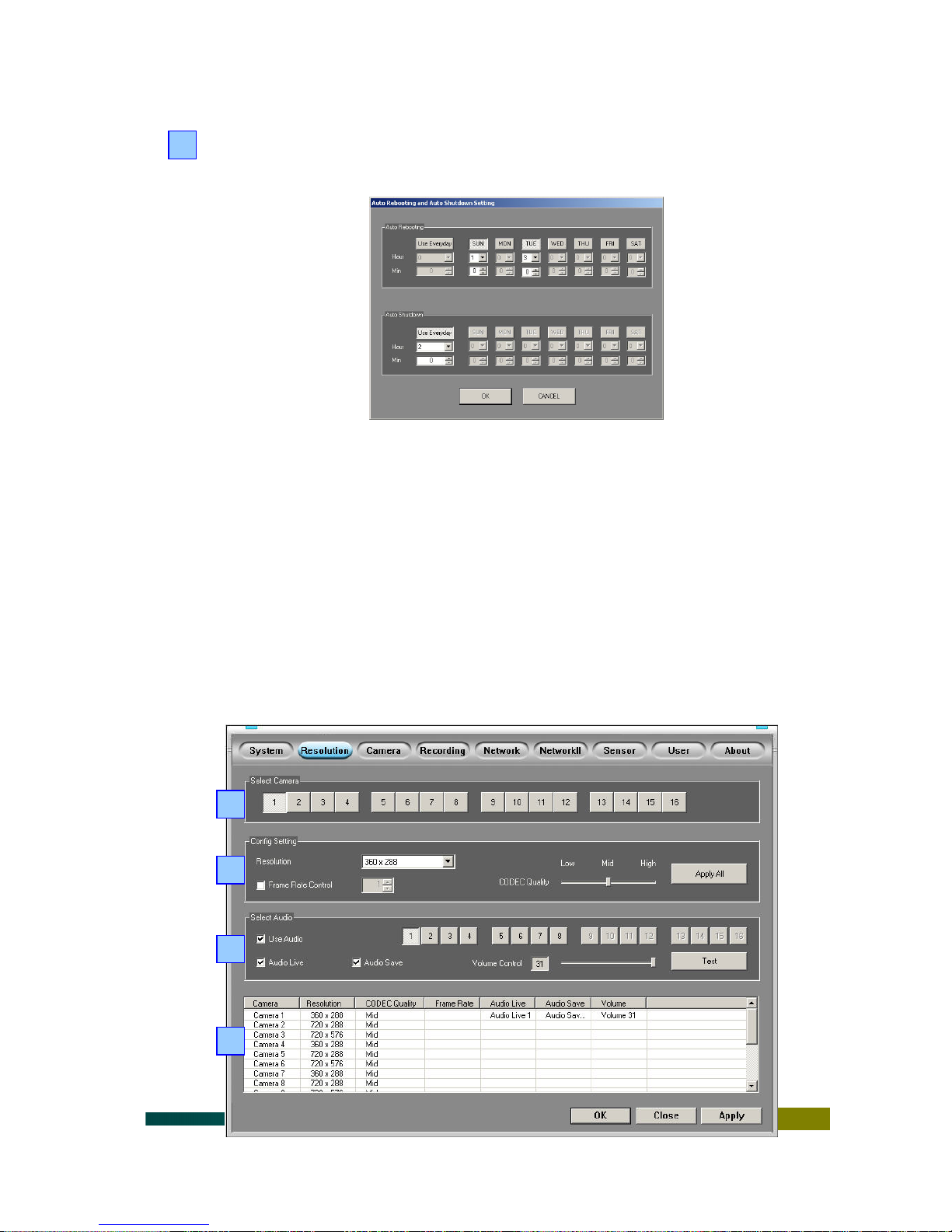
Click the “Setup” tab to activate the following menu window.
Specify ‘daily’ or a day of the week and the time.
Automatic System Restart : Automatically reboot the system at the selected (specified) time.
(Automatic restart does not run when the system is terminated, but runs while the system is
operating)
Automatic System Termination : Terminates the system at the selected (specified) time.
2-2. Resolution & Audio Setup
========================================== = = = = = = = = = = = = =
⊠ Click the “Resolution” tab to display the following setup window.
1
2
3
4
18

Camera Selection: Select a camera to configure.
1
Camera Selection : Select a camera to apply the configuration (to select the setup values for a
specified camera)
Environment Setup : Configure the resolution environment
2
Resolution : Select one of saved resolution
( NTSC : Select one from 640 x 480, 640 x 240, or 320 x 240)
( PAL : Select one from 720 x 588, 720 x 288, or 360 x 288)
Record Speed Setup : Select the record speed of the selected camera
(Select from 1~30 fps; Those exceeding the maximum capacity is recorded within the saving
capacity of the system.)
MPEG4 coder/decoder image quality : Select one out of three image qualities
“Apply All” tab : Use to apply the same condition to all cameras
Voice Selection : Configures the audio
3
Audio to Use : Select the input number of audio to use
(The audio number needs not to be same to the camera number.)
Audio Live : Select the audio to hear now
Audio Record : Select the audio to record now
Audio Control : Adjust the input audio level (check with the “practice” tab)
Refer to this window to check the application of configuration of all cameras selected in the
4
“Resolution” tab.
Menu can be extended horizontally when checking the details.
19
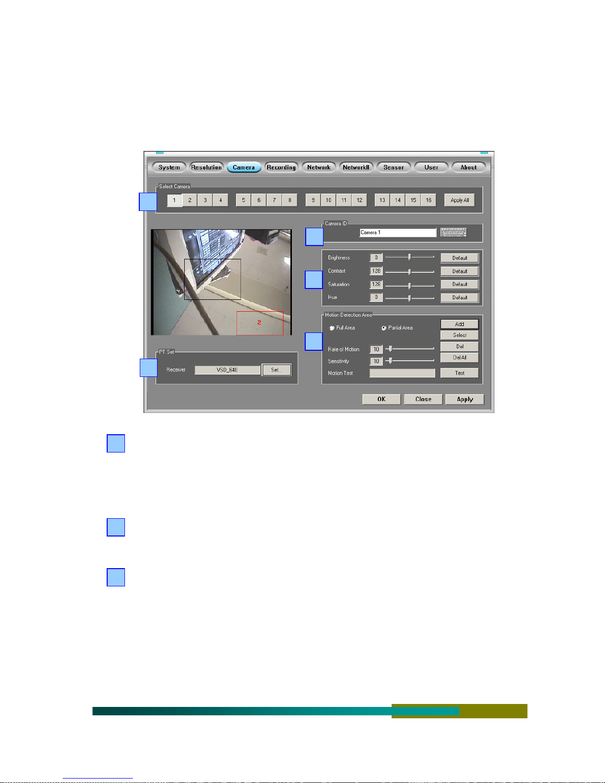
2-3. Camera Setup
========================================== = = = = = = = = = = = = =
⊠ Click the “Camera” tab to display the following setup window.
1
2
3
4
5
Camera Selection : Select a camera to configure.
1
Camera Selection : Select a camera to apply the configuration (to select the setup values for a
specified camera)
“Apply All” tab : Use to apply the same condition to all cameras
Camera Description : Enter the camera description (name).
2
Camera Description : Enter the name of the camera (image) (example, exit door).
Image Quality Adjustment : Adjust the camera image quality (color) for optimization.
3
Brightness : Adjust the brightness of the camera image
Contrast : Adjust the contrast of the camera image
Saturation : Adjust the saturation of the camera image
Color : Adjust the color of camera image
Default : Click to restore the default configuration set in the warehouse.
20
Detection Area Setup : Select the sensitivity and the area to detect motion.
4
[ How to Setup the Motion Area ]
Entire Area : Checks the motion of entire camera image.
Partial Area : Click the “Add” button after selecting the “Partial Area”, and then drag the
mouse in the left screen to configure the area (maximum 10 partial areas can be added).
How to Delete the Partial Area : Click the “Select” tab, click the partial area to delete, and
then click the “Delete” button.
Delete All : Click the “Delete All” button to delete all partial area added.
[ How to Setup the Motion Detection ] => [ Sensitive 0 ---- 100 Insensible ]
Rate of Detection : the level of detecting unnecessary motion by noise, defaulted at 10.
Sensitivity : the level of detecting little motion in small point, defaulted at 10.
The motions are checked by both the rate of detection and the sensitivity for accuracy.
Click the “Test” tab to display the status of testing motions on the screen.
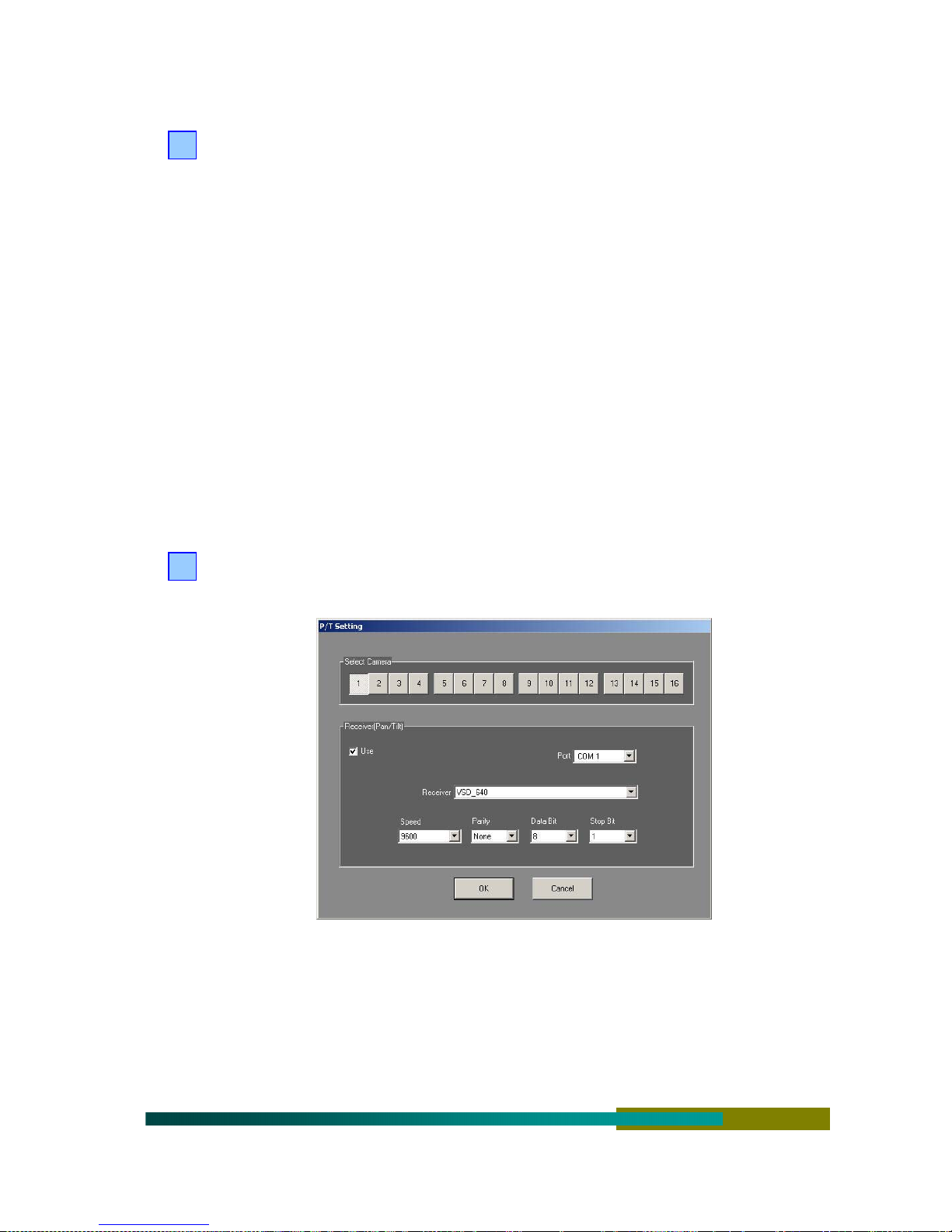
PanTilt Setup : Configure the PanTilt (rotational camera) to use.
5
Click the “Setup” tab to activate the following setup window.
Camera Selection : Select the camera the PanTilt is connected.
Receiver Setup : Check the “Enable” to activate the setup menu.
Select the port, type, communication speed, parity, data bit, and stop bit.
The configurations supported for the receiver or speed dome camera are listed in the table
21

The configurations supported for the receiver or speed dome camera.
index Receiver Baud rate parity Data Bit Stop Bit Preset
0 Dvna 9600 N 8 1 X
1 DY 9600 N 8 1 X
2 Fine 2400 N 8 1 X
3 Kalatel(N/A) 9600 N 8 1 X
4 Linlin 9600 N 8 1 X
5 Panasonic(wv-cs850) 19200 N 8 1 X
6 Pelco D 2400 N 8 1 O
7 Philips(tc8560,tc700) 9600 N 8 1 X
8 Serim 9600 N 8 1 X
9 Sungjin 4800 M 8 1 X
10 Vicon 4800 N 8 1 X
11 Dyuni 9600 E 8 1 X
12 MP200 9600 N 8 1 X
13 KD6 9600 N 8 1 X
14 Samsung(scc-641) 9600 N 8 1 X
15 Oriental 2400 O 8 1 X
16 Techwin 9600 N 8 1 X
17 OMNIVIEW 9600 N 8 1 X
18 CNB 9600 N 8 1 X
19 CTNCOM 9600 N 8 1 X
20 NIKO(NK-97CHE) 9600 N 8 1 X
21 SENSORMETIC 9600 N 8 1 O
22 NEOSSRX-1 4800 E 8 1 X
23 PT101 9600 N 8 1 X
24 PANASONIC V12 19200 N 8 1 O
25 VICONEXT N 8 1 X
26 SECURTEX_B 4800 N 8 1 X
27 SMAILCAM 19200 N 8 1 X
28 DRX502A,DSC-230S 9600 N 8 1 X
29 HSDN-251 9600 N 8 1 O
30 SAMSUNG SRX100A 9600 E 8 1 X
31 CNB-SMART 9600 N 8 1 X
32 HL(HRX-1000) 9600 N 8 1 X
22
 Loading...