

Page 1

LNS series
Standalone DVR
User’s Manual
1
Page 2

Table of Contents
0H1 FEATURES AND SPECIFICATIONS ................................................................. 181H11
1H1.1 Features .................................................................................................................................................... 182H11
2H1.2 Specifications............................... ......................................................... ................................................... 183H11
3H2 OVERVIEW AND CONTROLS ........................................................................... 184H14
4H2.1 Front Panel ............................................................................................................................................... 185H14
5H2.2 Rear Panel ...................................... .......................... ......................... ............................. ......................... 186H15
6H2.2.1 Overview .............................................................................................................................................. 187H15
7H2.2.2 Connection Sample ........................................................................................................................... 188H16
8H2.3 Remote Control ................ ................................... ..................................... .................................... ........... 189H17
9H2.4 Mouse Control .................................... ................................. ................................. ................................... 190H18
10H2.5 Virtual Keyboard & Front Panel ............................................................................................................ 191H19
11H2.5.1 Virtual Keyboard ................................................................................................................................. 192H19
12H2.5.2 Front Panel .......................................................................................................................................... 193H19
13H3 INSTALLATION AND CONNECTIONS .............................................................. 194H20
14H3.1 Check Unpacked DVR ........................................................................................................................... 195H20
15H3.2 HDD Installation .................................... ............................ ............................ ............................... ........... 196H20
16H3.2.1 Choose HDDs ..................................................................................................................................... 197H20
17H3.2.2 Calculate HDD Size ........................................................................................................................... 198H20
18H3.2.3 HDD Installation ................................................................................................................................. 199H20
19H3.3 CD/DVD Burner Installation ..................................... ..................................... ........................................ 200H21
2
Page 3

20H3.4 Desktop and Rack Mounting ........................................ .... ..... ....... ..... .... ....... ..... ..... ....... ..... .... ..... ....... .. 201H22
21H3.4.1 Desktop Mounting .............................................................................................................................. 202H22
22H3.4.2 Rack Mounting .................................................................................................................................... 203H22
23H3.5 Connecting Power Supply ..................................................................................................................... 204H22
24H3.6 Connecting Video Input and Output Devices ............................................ .......... ......... ............ ......... 205H22
25H3.6.1 Connecting Video Input .................................................................................................................... 206H22
26H3.6.2 Connecting Video Output ................................................................................................................. 207H23
27H3.7 Connecting Audio Input & Output, Bidirectional Audio, Looping Video, Matrix........................... 208H24
28H3.7.1 Audio Input/One Audio Output ........................................................................................................ 209H24
29H3.7.2 Looping video ..................................................................................................................................... 210H25
30H3.7.3 Matrix Video Output ........................................................................................................................... 211H25
31H3.7.4 Alarm Input and Relay Output ......................................................................................................... 212H25
32H3.7.5 Alarm Input .......................................................................................................................................... 213H25
33H3.7.6 Alarm Output ....................................................................................................................................... 214H26
34H3.7.7 Alarm Input and Output Details ........................................................................................................... 215H26
35H3.7.8 Relay Output Description .................................................................................................................. 216H27
36H3.8 RS232 ......................................... ............................... ................................ ............................................... 217H29
37H3.9 RS485 ......................................... ............................... ................................ ............................................... 218H29
38H3.10 Other Interfaces .................................... ....... ....... ......... ....... ....... .......... ....... ....... ....... ......... ....... ....... ....... 219H30
39H4 OVERVIEW OF NAVIGATION AND CONTROLS ............................................. 220H31
40H4.1 Login, Logout & Main Menu .................................................................................................................. 221H31
41H4.1.1 Login ..................................................................................................................................................... 222H31
42H4.1.2 Main Menu ........................................................................................................................................... 223H31
43H4.1.3 Logout .................................................................................................................................................. 224H32
44H4.1.4 Auto Resume after Power Failure ................................................................................................... 225H32
45H4.1.5 Replace Button Battery ..................................................................................................................... 226H32
46H4.2 Recording Operation ....................................... ........................................... ........................................ .... 227H32
47H4.2.1 Live Viewing ........................................................................................................................................ 228H32
48H4.2.2 Manual record ..................................................................................................................................... 229H33
3
Page 4

49H4.3 Search & Playback .............. ............................. ............................ .............................. ............................ 230H35
50H4.3.1 Search Menu ....................................................................................................................................... 231H35
51H4.3.2 Basic Operation .................................................................................................................................. 232H36
52H4.3.3 Calendar .............................................................................................................................................. 233H37
53H4.4 Record Setup (Schedule) ...................................................................................................................... 234H38
54H4.4.1 Schedule Menu ........................................................................................................................................ 235H38
55H4.4.2 Basic Operation ....................................................................................................................................... 236H38
56H4.5 Motion Detect.................................. ........................................................ ................................................. 237H40
57H4.5.1 Go to Motion Detect Menu ..................................................................................................................... 238H40
58H4.5.2 Motion Detect ........................................................................................................................................... 239H40
59H4.5.3 Video Loss ................................................................................................................................................ 240H41
60H4.5.4 Camera Mask Detect .............................................................................................................................. 241H42
61H4.6 Alarm Setup and Alarm Activation ....................................................................................................... 242H43
62H4.6.1 Go to alarm setup interface .............................................................................................................. 243H43
63H4.6.2 Alarm setup ......................................................................................................................................... 244H43
64H4.7 Backup ..................... ............................................. ............................................... ..................................... 245H44
65H4.7.1 Detect Device .......................................................................................................................................... 246H44
66H4.7.1 Backup ................................................................................................................................................. 247H44
67H4.8 PTZ Control and Color Setup ......................................... ................................... ................................... 248H45
68H4.8.1 Cable Connection .................................................................................................................................... 249H45
69H4.8.2 PTZ Setup ................................................................................................................................................ 250H45
70H4.8.3 3D Intelligent Positioning Key .............................................................................................................. 251H47
71H4.9 Preset/ Patrol/Pattern/Scan ............................ ....................... ..................... ........................ .................. 252H47
72H4.9.1Preset Setup ............................................................................................................................................. 253H48
73H4.9.2 Activate Preset ........................................................................................................................................ 254H48
74H4.9.3 Patrol Setup (Tour setup) ...................................................................................................................... 255H48
75H4.9.4 Activate Patrol (tour) .............................................................................................................................. 256H49
76H4.9.5 Pattern Setup .......................................................................................................................................... 257H49
77H4.9.6 Activate Pattern Function ...................................................................................................................... 258H49
78H4.9.7 Auto Scan Setup ..................................................................................................................................... 259H49
79H4.9.8 Activate Auto Scan ................................................................................................................................. 260H50
80H4.10 Dome Menu Control ......................................... ............................................... ..................................... 261H50
4
Page 5

81H5 UNDERSTANDING OF MENU OPERATIONS AND CONTROLS .................... 262H51
82H5.1 Menu Tree ................................................................................................................................................ 263H51
83H5.2 Main Menu ............................... ....... .... ..... ....... ..... ..... .... ....... ..... ..... ....... .... ..... ....... ..... ..... .... ..................... 264H51
84H5.3 Setting ...................... .................................................... .................................................... ......................... 265H52
85H5.3.1 General ................................................................................................................................................ 266H52
86H5.3.2 Encode ................................................................................................................................................. 267H53
87H5.3.3 Schedule .............................................................................................................................................. 268H54
88H5.3.4 RS232 .................................................................................................................................................. 269H54
89H5.3.5 Network ................................................................................................................................................ 270H54
90H5.3.6 Alarm .................................................................................................................................................... 271H59
91H5.3.7 Detect ................................................................................................................................................... 272H59
92H5.3.8 Pan/Tilt/Zoom ..................................................................................................................................... 273H59
93H5.3.9 Display ................................................................................................................................................. 274H60
94H5.3.10 Default ............................................................................................................................................. 275H61
95H5.4 Search ....................................................................................................................................................... 276H61
96H5.5 Advanced....................................................... ........................................................ ............................ ....... 277H61
97H5.5.1 Hard Disk Management .................................................................................................................... 278H62
98H5.5.2 Alarm Output ....................................................................................................................................... 279H63
99H5.5.3 Alarm Input .......................................................................................................................................... 280H63
100H5.5.4 Manual Record ................................................................................................................................... 281H63
101H5.5.5 Account ................................................................................................................................................ 282H63
102H5.5.6 Auto Maintain ...................................................................................................................................... 283H64
103H5.5.7 TV Adjust ............................................................................................................................................. 284H65
104H5.5.8 Video Matrix (For DVR 1604LNH-S Series Only) ........................................................................ 285H65
105H5.6 Information ........................ ............................ .......................... ......................... ........................................ 286H69
106H5.6.1 Hard Disk Information ....................................................................................................................... 287H69
107H5.6.2 BPS ....................................................................................................................................................... 288H70
108H5.6.3 Log ........................................................................................................................................................ 289H70
109H5.6.4 Version ................................................................................................................................................. 290H70
110H5.6.5 Online Users ....................................................................................................................................... 291H71
111H5.7 Exit ............................................................................................................................................................. 292H71
5
Page 6

112H6 ABOUT AUXILIARY MENU .......................................................... ...................... 293H72
113H6.1 Go to Pan/Tilt/Zoom Menu .................................................................................................................... 294H72
114H6.1.1 3D Intelligent Positioning Key .......................................................................................................... 295H73
115H6.2 Preset /Patrol / Pattern /Border Function .................................................... ..................................... 296H73
116H6.2.1 Preset Setup ....................................................................................................................................... 297H74
117H6.2.2 Activate Preset ................................................................................................................................... 298H74
118H6.2.3 Patrol Setup ........................................................................................................................................ 299H74
119H6.2.4 Activate Patrol..................................................................................................................................... 300H74
120H6.2.5 Pattern Setup ...................................................................................................................................... 301H74
121H6.2.6 Activate Pattern Function ................................................................................................................. 302H75
122H6.2.7 Border Setup ....................................................................................................................................... 303H75
123H6.2.8 Activate Border Function .................................................................................................................. 304H75
124H6.3 Dome Menu Control ........ .............................. ............................ ............................... ............................ .. 305H75
125H7 WEB CLIENT OPERATION ................................................................................ 306H76
126H7.1 Network connection ................................................................................................................................ 307H76
127H7.2 Login and logout............................... ............................ ......................................................... .................. 308H76
128H7.3 Go to Real-time Monitor Mode ............. ...................................... ........................................ .................. 309H77
129H7.4 Video (Right Mouse Menu Operation) ................................. ............................ ............................... .... 310H78
130H7.4.1 Real time Monitor ............................................................................................................................... 311H78
131H7.4.2 Multi-camera Preview ........................................................................................................................ 312H78
132H7.4.3 Start Dialog ......................................................................................................................................... 313H78
133H7.4.4 Decode Quality ................................................................................................................................... 314H78
134H7.4.5 Playback Control Bar ......................................................................................................................... 315H78
135H7.4.6 PTZ Control ......................................................................................................................................... 316H79
136H7.4.7 Volume Adjustment ........................................................................................................................... 317H80
137H7.4.8 Alarm Setting ...................................................................................................................................... 318H80
138H7.4.9 Network Data Flux ............................................................................................................................. 319H80
139H7.4.10 Full Screen ..................................................................................................................................... 320H80
140H7.4.11 Resize Video .................................................................................................................................. 321H81
141H7.4.12 Video Windows .............................................................................................................................. 322H81
6
Page 7

142H7.5 Search ....................................................................................................................................................... 323H81
143H7.5.1 Download ............................................................................................................................................. 324H82
144H7.6 Configure .................................... ................................................. .................................................. ........... 325H83
145H7.6.1 Load and Save Configuration .......................................................................................................... 326H84
146H7.6.2 General ................................................................................................................................................ 327H85
147H7.6.3 Schedule .............................................................................................................................................. 328H85
148H7.6.4 Image ................................................................................................................................................... 329H86
149H7.6.5 Alarm .................................................................................................................................................... 330H87
150H7.6.6 Motion Detection ................................................................................................................................ 331H88
151H7.6.7 Network ................................................................................................................................................ 332H89
152H7.6.8 Video Parameter ................................................................................................................................ 333H89
153H7.7 Assistant ..................... ..................................... ........................................ ...................................... ........... 334H90
154H7.7.1 User Manage ...................................................................................................................................... 335H90
155H7.7.2 Record Control ................................................................................................................................... 336H93
156H7.7.3 Log Information .................................................................................................................................. 337H93
157H7.7.4 Date and Time .................................................................................................................................... 338H94
158H7.7.5 System Information ............................................................................................................................ 339H94
159H7.7.6 Alarm Prompt ...................................................................................................................................... 340H94
160H7.7.7 Channel Name .................................................................................................................................... 341H95
161H7.7.8 Upgrade BIOS .................................................................................................................................... 342H95
162H7.7.9 Reboot .................................................................................................................................................. 343H96
163H7.7.10 Matrix (Applies for some special series only) .......................................................................... 344H96
164H7.7.11 About ............................................................................................................................................... 345H96
165H7.7.12 Mail .................................................................................................................................................. 346H96
166H7.8 Un-install Web Control ........................................................................................................................... 347H98
167H8 PRO SURVEILLANCE SYSTEM ........................................................................ 348H99
168H8.1 Features .................................................................................................................................................... 349H99
169H8.2 Environment ............................................................................................................................................. 350H99
170H8.3 Overview ................................................................................................................................................... 351H99
171H8.4 More Details ........................................................................................................................................... 352H100
7
Page 8

172H9 RS232 OPERATION ......................................................................................... 353H101
173H9.1 Network Connection .......................... .................................................. ................................................. 354H101
174H9.2 Keyboard .................... .............................. ............................ ............................ ...................................... 355H101
175H10 FAQ ................................................................................................................... 356H102
176HAPPENDIX A HDD CAPACITY CALCULATION ..................................................... 357H104
177HAPPENDIX B COMPATIBLE USB DRIVE LIST ................................................... 358H105
178HAPPENDIX C COMPATIBLE CD/DVD BURNER LIST ......................................... 359H106
179HAPPENDIX E COMPATIBLE SATA HDD LIST ..................................................... 360H107
8
Page 9

Welcome
Thank you for purchasing our DVR!
This operating manual is designed to be a reference tool for the installation and
operation of your system.
Here you can find information about this series DVR features and functions, as well
as a detailed menu tree.
Before installation and operation please read the following safeguards and warnings
carefully!
9
Page 10

Important Safeguards and Warnings
1.Electrical safety
All installation and operation here should conform to local electrical safety codes.
We assume no liability or responsibility for all the fires or electrical shock caused by
improper handling or installation.
2.Transportation security
Heavy stress, violent vibration or water splash are not allowed during transportation,
storage and installation.
3.Installation
Keep upwards. Handle with care.
Do not apply power to the DVR before completing installation.
Do not place objects on the DVR
4.Qualified engineers needed
All the examination and repair work should be done by the qualified service
engineers.
We are nor liable for any problems caused by unauthorized modifications or
attempted repair.
5.Environment
The DVR should be installed in a cool, dry place away from direct sunlight,
inflammable, explosive substances and etc.
6. Accessories
Be sure to use all the accessories recommended by manufacturer.
Before installation, please open the package and check all the components listed
below are included:
z One power cable
z One Ethernet cable
z Four HDD cables
z Alarm & relay terminal blocks
z Extensional cable(for audio, loop & matrix)
z One remote control(including the battery)
z One USB mouse
z One CD(including DVR manual, client & small tools)
z Warranty card
z A package of installation fittings
Contact your local retailer ASAP if something is missing in your package.
Note: Any changes of this manual made to the actual product are subjects to
no further notification.
10
Page 11

1 FEATURES AND SPECIFICATIONS
1.1 Features
This series DVR has the following features:
z Most popular model, widely accepted in the worldwide security industry
z H.264 compression algorithm ideal for standalone DVR
z Real-time live display up to 16 cameras, 400/480 fps recording for CIF
z USB2.0 and SATA HDD supported
z Pentaplex function: live, recording, playback, backup & remote access
z 4 HDDs supported & CD-RW/DVD-RW supported
z Multiple control methods: front panel, IR remote control, DAHUA keyboard, USB
mouse and network keyboard.
z Smart video detection: motion detection, camera masking, video loss.
z Smart camera settings: privacy masking, camera lock, color setting, and title
display
z Pan Tilt Zoom and Speed Dome Control: more than 60 protocols supported,
preset, scan, auto pan, auto tour, pattern, auxiliary function supported. And with
Dahua Speed Dome, 3D intelligent positioning function supported.
z Easy backup methods: USB devices, CD-RW/DVD-RW & network download
z Alarm triggering screen tips, buzzer, PTZ preset, matrix output, e-mail, FTP
upload.
z Smart HDDs Management: non-working HDD hibernation, HDD faulty alarm,
Raid function.
z Powerful network software: built-in web server, multi-DVR client & CMS.
Networking access for remote live viewing, recording, playback, setting, system
status, event log, e-mail & ftp function.
1.2 Specifications
Model
LNS-04/08/16 4/8/16 channel video basic model
LNS-16H 16 channel loop matrix and audio/video model
System
Main Processor High performance embedded microprocessor
Operating System Embedded LINUX
System Resources Pentaplex function: live, recording, playback, backup &
remote access
User Interface GUI, on-screen menu tips.
Control Device USB mouse, DAHUA keyboard, IR remote
control, network keyboard,.
Input Method Numeral/Character/Denotation
System Status HDD status, data stream statistics, log record, bios
version, on-line user and etc.
Video
11
Page 12

Video Input 4/8/16 Channel, BNC, 1.0Vp-p, 75Ω, looping(optional)
Video Output 2 channel TV output BNC, 1.0Vp- p, 75,1 VGA output
Video Standards PAL(625Line,50f/s),NTSC(525Line,60f/s)
Video Compression H.264
Video Resolution Format NTSC PAL
CIF 352 *240 352 *288
Video Recording CIF: PAL 1f/s~25f/s NTSC 1f/s~30f/s
Video Display Split Full and multiple screen display, 1 / 4 / 8 / 9 / 16
Tour Display Support
Image Quality 1~6 level(level 6 is the best)
Privacy Masking Self-defined four-sided zone for privacy masking for each
camera
Camera Lock Camera locked for users
Camera Adjustment Adjust color according to different time period
Video Information Camera title, time, video loss, camera lock, motion
detection, recording
TV Output Adjustment Adjust TV output color & display zone
Audio(Only LNS-16H with audio)
Audio Input 4 channel, BNC, 200-2800mV, 30K
Bidirectional Talk Input 1 channel, BNC, 200-2800mV, 30K
Audio Output 1 channel, BNC, 200-3000mv, 5K
Audio Compression ADPCM
Video Detection & Alarm
Motion Detection Zones: 192 (16*12) detection zones
Sensitivity: 1~6 (level 6 is highest)
Trigger recording, PTZ movement, tour, alarm & FTP
Video Loss Trigger recording, PTZ movement, tour, alarm & FTP
Camera masking Trigger recording, PTZ movement, tour, alarm & FTP
Alarm Input 4/16/16 channel, programmable, ground, manual
open/closed
Trigger recording, PTZ movement, tour, alarm & FTP
Relay output 3/6/6 channel, 30VDC, 1A, NO/NC, form-C,
Hard Disk
Hard Disk 4 SATA ports, 4 HDDs supported.
Space Occupation Audio :14.4MB/H Video :56~400MB/H
HDD Management Hard disk hibernation technology, HDD faulty alarm &
Raid (Redundancy)
12
Page 13

Record, Playback & Backup
Recording Mode Manual, continuous, video detection (including motion
detection, camera masking, video loss), Alarm
Recording Priority Manual >Alarm >Video Detection >Continuous.
Recording Interval 1 to 120 minutes (default: 60 minutes)
Overwrite Mode Support
Raid Function Support
Search Mode Time/Date, Alarm, Motion Detection & exact search
(accurate to second)
Playback 1-channel playback ; Play, pause, stop, rewind, fast
play, slow play, next file, previous file, next camera,
previous camera, full screen, repeat, shuffle, backup
selection.
Digital Zoom Selected zone can zoom into full screen during
playback
Backup Mode Flash stick/ USB HDD/ USB CD-RW/DVD-RW/ built-
in SATA Burner/ network download
Network
Interface RJ-45 Port (10/100M)
Network Functions TCP/IP, DHCP, DDNS, PPPoE, E-mail, FTP
Remote operation Monitor, PTZ control, playback, system setting, file
download, log information
Auxiliary Interface
USB Interface 2 ports, 1 for mouse control, 1 for backup.
RS232 DAHUA keyboard, PC communication
RS485 PTZ control
Environmental
Power Supply 220V 50Hz / 110V 60Hz
Power Consumption 25W/30W/40W
Working Temperature -10℃~+55℃
Power Consumption 25W/30W/40W
Working Humidity 10%~90%
Atmosphere Pressure 86kpa~106kpa
Dimension 1.5U, 440mmx460mmx68mm (W*D*H)
Weight 6.0KG
Mounting Desktop or rack
Features and specification are subject to change without prior notice.
13
Page 14
2 OVERVIEW AND CONTROLS
This section provides information about front panel and rear panel. When you install
this series DVR for the first time, please refer to this part first.
1.32.1 Front Panel
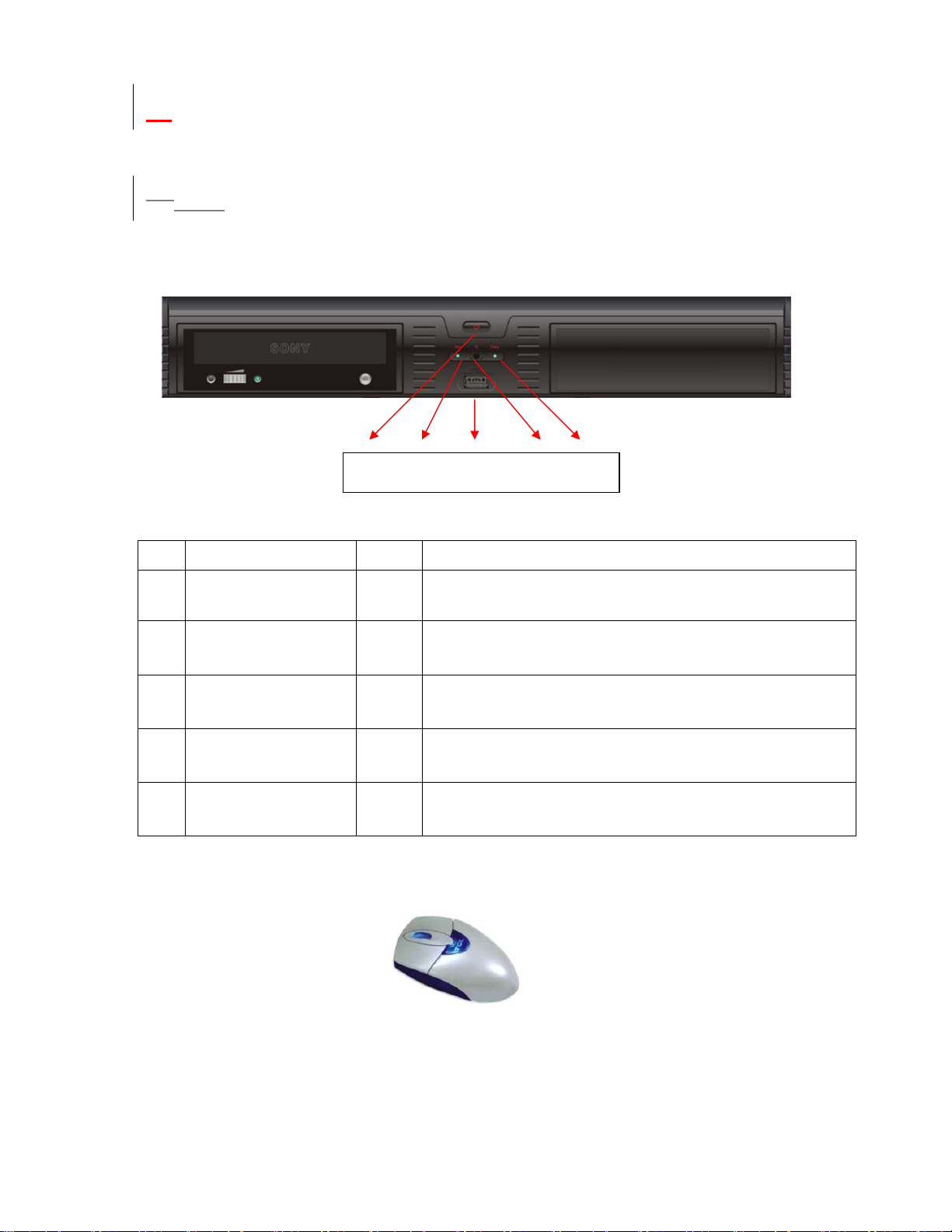
This series DVR front panel is shown as in
361H
Figure 2-1 .
1 2 3 4 5
Figure 2-1
S/N Name Icon Function
1 Power button POWER Power button. Press this button for three seconds to shut down DVR.
2 Record indication light
When DVR is recording, this indication light turns on.
3 USB port
4 Remote control receiver To receive remote control signal.
5
Power indication
light
When connect to power, this indication light turns on.
Connect to USB mouse or USB backup devices.
Please insert the USB Mouse to operate the DVR.
Figure 2-2
Page 15
1.42.2 Rear Panel
1.4.12.2.1 Overview
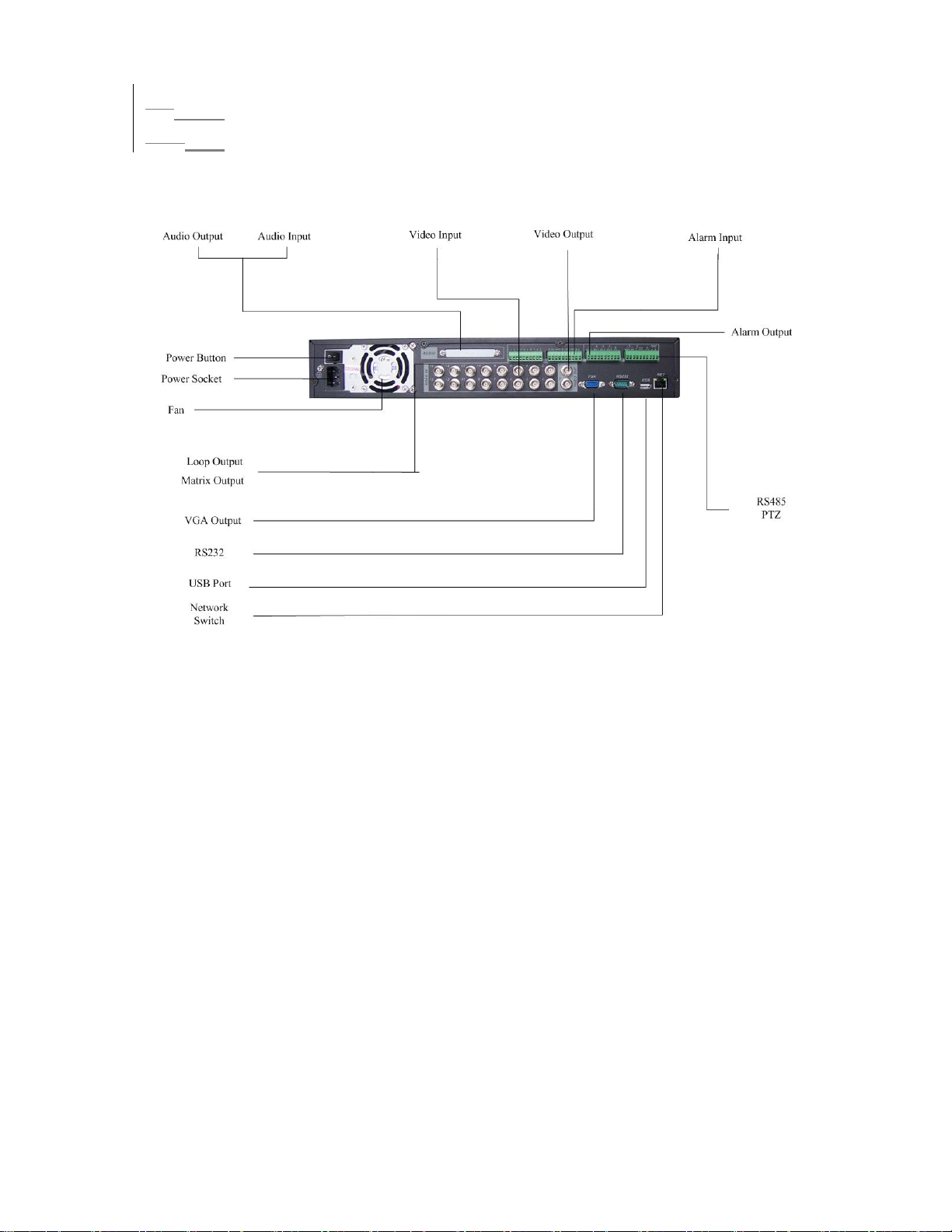
Please refer to 362HFigure 2-3 for real panel information.
Figure 2-3
15
Page 16
2.2.2 Connection Sample
1.4.2
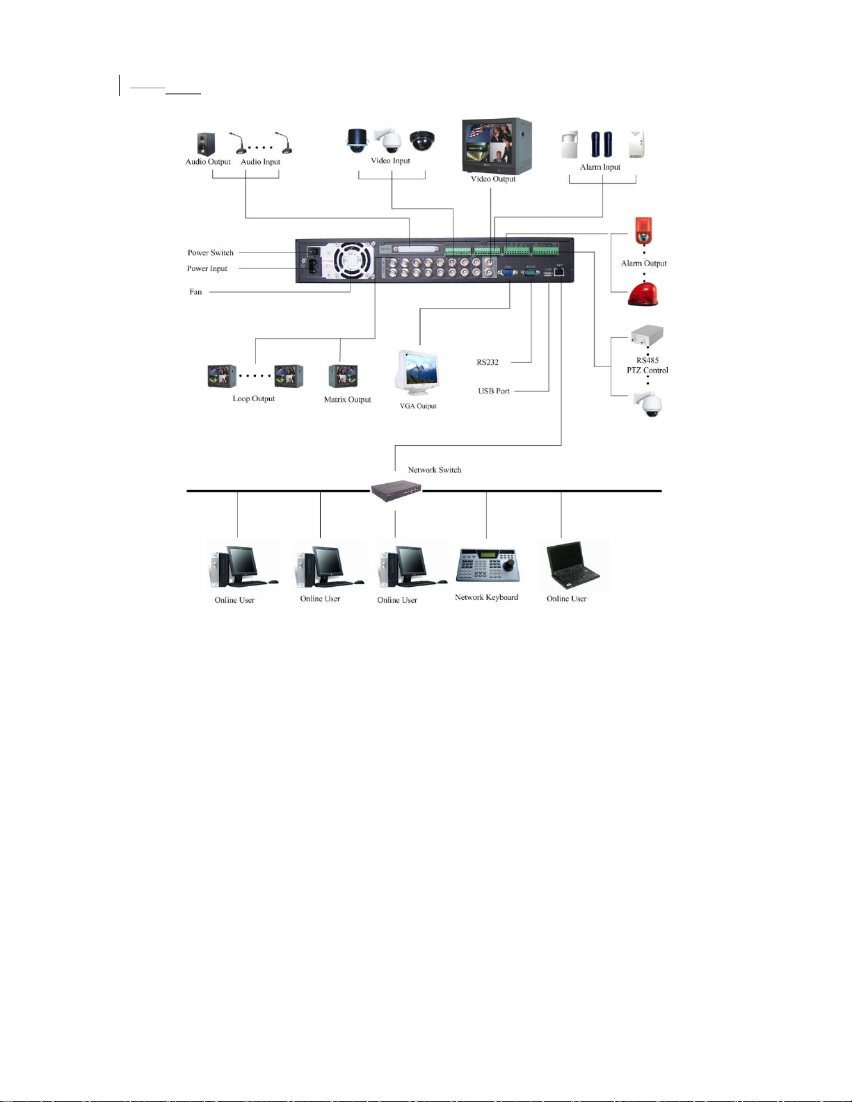
Here is a connection sample for your reference. See 363HFigure 2-4.
Figure 2-4
Model LNS-04/08/16 LNS-16H
Audio Input NO 4 channel
Loop Output NO 16 channel
Matrix Output NO 1 channel
Bidirectional- NO 1 channel
Audio Input
16
Page 17

1.52.3 Remote Control
The remote control interface is shown next.
Serial
Number
1 remote switch
2 Multiple-window switch
3 0-9 number key
4 Record
5 Auxiliary key
6 Confirm /menu key
7 Cancel
8 Direction key
9 forward
10 Previous
11 Back
12 Next
13 Slow play
14 Stop
15 Fast play
16 Play/Pause
Function
Figure 2-5
17
Page 18

1.62.4 Mouse Control
Left click
mouse
System pops up password input dialogue box if you have not logged in.
In real-time monitor mode, you can go to the main menu.
When you have selected one menu item, left click mouse to view menu
content.
Implement the control operation.
Modify checkbox or motion detection status.
Click combo box to pop up drop down list
In input box, you can select input methods. Left click the corresponding
button on the panel you can input numeral/English character
(small/capitalized). Here stands for backspace button. _ stands for space
button.
In English input mode: _stands for input a backspace icon and stands for
deleting the previous character.
Double left
click mouse
In numeral input mode: _ stands for clear and stands for deleting the
previous numeral.
When input special sign, you can click corresponding numeral in the front
panel to input. For example, click numeral 1 you can input“/” , or you can click
the numeral in the on-screen keyboard directly.
Implement special control operation such as double click one item in the file
list to playback the video.
In multiple-window mode, double left click one channel to view in full-window.
Double left click current video again to go back to previous multiple-window
mode.
18
Page 19
Right click
mouse
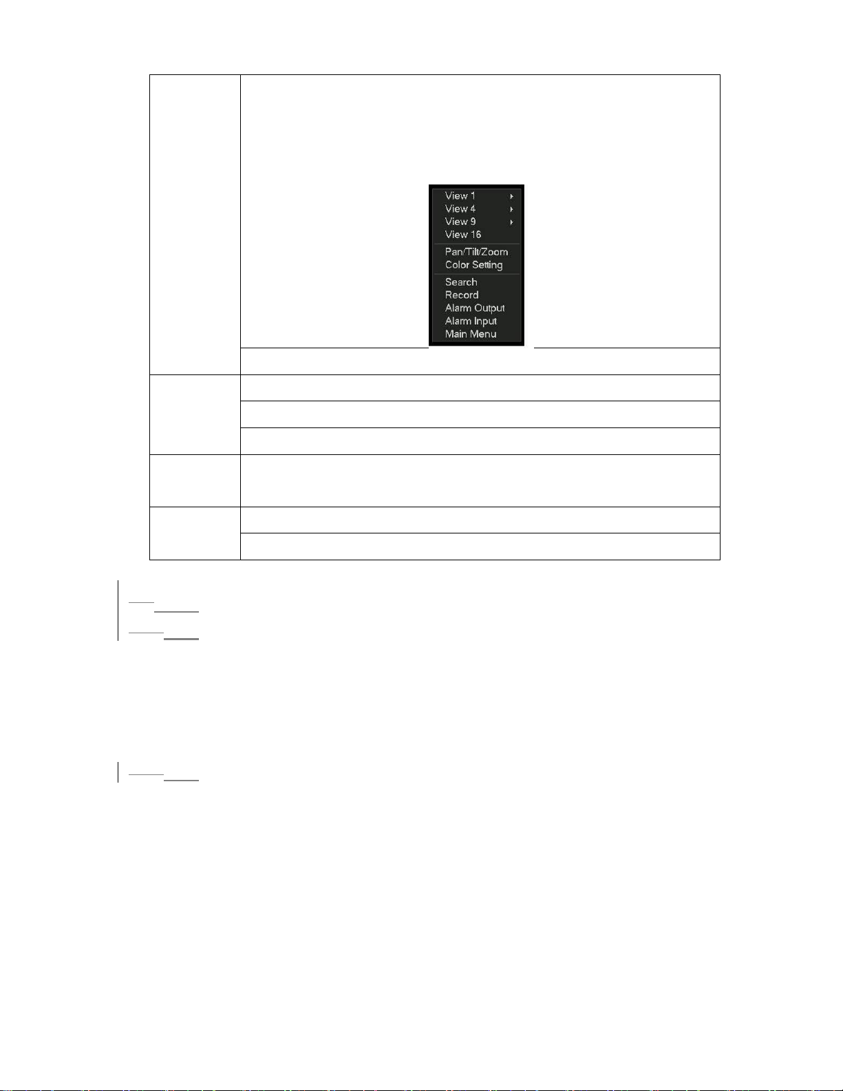
In real-time monitor mode, pops up shortcut menu: one-window, four-window,
nine-window and sixteen-window, Pan/Tilt/Zoom, color setting, search,
record, alarm input, alarm output, main menu.
Among which, Pan/Tilt/Zoom and color setting applies for current selected
channel.
If you are in multiple-window mode, system automatically switches to the
corresponding channel.
Exit current menu without saving the modification.
Press
middle
button
Move
mouse
Drag mouse Select motion detection zone
In numeral input box: Increase or decrease numeral value.
Switch the items in the check box.
Page up or page down
Select current control or move control
Select privacy mask zone.
1.72.5 Virtual Keyboard & Front Panel
1.7.12.5.1 Virtual Keyboard
The system supports two input methods: numeral input and English character (small
and capitalized) input.
Move the cursor to the text column, the text is shown as blue, input button pops up
on the right. Click that button to switch between numeral input and English input
(capitalized and small), Use > or < to shift between small character and capitalized
character.
2.5.2 Front Panel
1.7.2
Move the cursor to the text column. Click Fn key and use direction keys to select
number you wanted. Please click enter button to input.
19
Page 20
23 Installation and Connections
Note: All the installation and operations here should conform to your local
electric safety rules.
2.13.1 Check Unpacked DVR
When you receive the DVR from the shipping agency, please check whether there is
any visible damage to the DVR appearance. The protective materials used for the
package of the DVR can protect most accidental clashes during transportation. Then
you can open the box to check the accessories.
Please check the items in accordance with the list on the warranty card. Finally you
can remove the protective film of the DVR.
2.23.2 HDD Installation
2.2.13.2.1 Choose HDDs
We recommend Seagate HDD of 7200rpm or higher.
3.2.2 Calculate HDD Size
2.2.2
This series have no limit to HDD capacity. You can use 120G-750G HDD to
guarantee higher stability.
The formula of total HDD size is:
Total Capacity (MB) = Camera Amount * Recording Hours * HDD Usage Per Hour
(M/h)
H.264 compression is ideal for standalone DVRs. It can save more than 30% HDD
capacity than MPEG4. When you calculate the total HD capacity, you should
estimate the average HDD capacity per hour for each channel.
For example, for a 4-ch DVR, the average capacity of HDD usage per hour per
channel is 200M/h. Now if you hope the DVR can record the video 12 hours each
day for 30 days, the total capacity of HDDs needed is: 4 channels * 30 days * 12
hours * 200 M/h = 288G. So you need to install one 300G HDD or 2 160G HDDs.
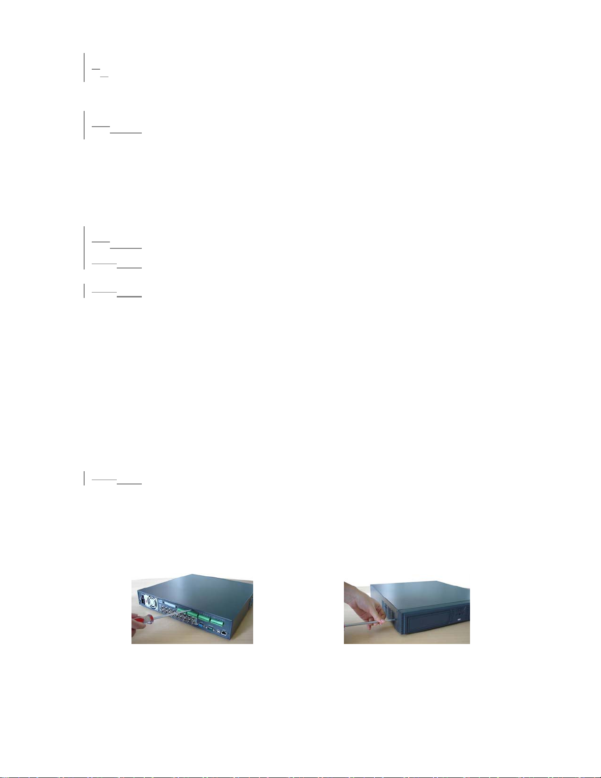
3.2.3 HDD Installation
2.2.3
Data ribbons, fastening screws and smart HDD shelf design are already provided in
the accessories.
Please follow the instructions below to install hard disk.
①Dismantle the screws from the front and real panels.
20
Page 21
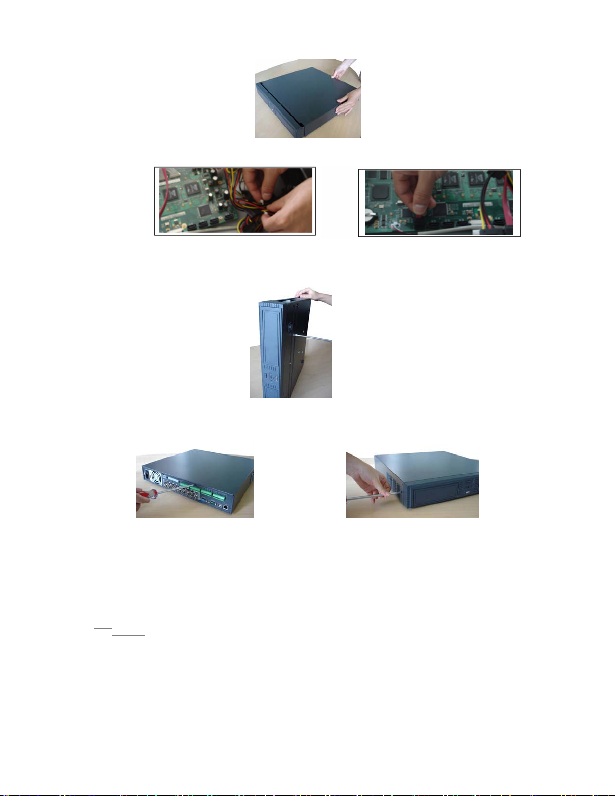
②Remove the upper cover
③Unfasten the HDD power cable. ④Connect to data connection cable
and then plug the HDD power cable.
⑤
Fix the HDD in the DVR.
When installing HDD, please keep the side of the screw holes face down.
Place the upper cover back and screw firmly .
⑥
After HDD installation, please check connection of data ribbon and power cord.
Note:
For LN SATA series, the HDD ports are SATA and there is no need to set
master/slave HDD.
2.33.3 CD/DVD Burner Installation
For USB burners, you need to install USB series burner.
This series DVR is compatible with various burner brands popular in today’s market.
You can consult our local technical support or visit our website for more information.
21
Page 22

2.43.4 Desktop and Rack Mounting
2.4.13.4.1 Desktop Mounting
To prevent surface damage, please make sure that the rubber feet are securely
installed on the four corners of the bottom of the unit.
Position the unit to allow for cable and power cord clearance at the rear of the unit.
Be sure that the air flow around the unit is not obstructed.
3.4.2 Rack Mounting
2.4.2
The DVR occupies two rack units of vertical rack space.
The hardware necessary to mount the DVR into a rack is supplied with the unit.
Rear doors may be used only on rack columns that are more than 26 inches (66.0
cm) deep.
Install the cabinet in ventilated place. Avoid extreme heat, humid or dusty conditions.
You can use a soft dry brush to clean opening outlet, cooling fan and etc regularly.
2.53.5 Connecting Power Supply
Please check input voltage and device power button match or not.
We recommend you use UPS to guarantee steady operation, DVR life span, and
other peripheral equipments operation such as cameras.
2.63.6 Connecting Video Input and Output Devices
2.6.13.6.1 Connecting Video Input
The DVR automatically detects the video standard (PAL or NTSC) whenever you
connect a video input. It accepts both color and black-and-white and analog video.
NOTE:
z Enabling line lock on cameras may cause video distortion. There may be noise in
the camera’s power source. If video from one or more cameras is distorted, we
recommend you disable line lock on the camera as your first troubleshooting step.
z If a video distribution amplifier is installed between the video source and the DVR,
do not set the output video level above 1 Vp-p.
To connect each video input:
1. Connect a coaxial cable to the camera or other analog video source.
2. Connect the coaxial cable to the video in connector on the rear panel.
Please refer to
NOTE:
You need to use a BNC installation tool to connect coaxial cables to the rear panel.
364HFigure 3-1 for more information.
22
Page 23
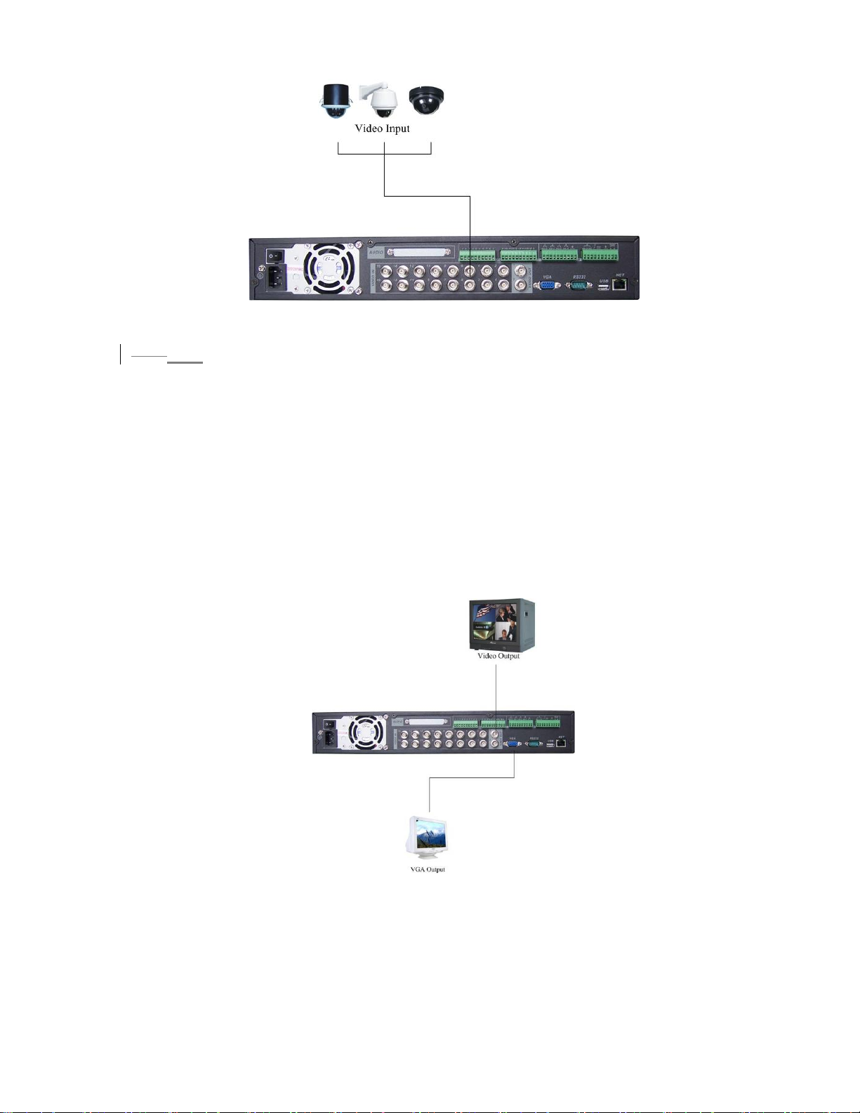
Figure 3-1
3.6.2 Connecting Video Output
2.6.2
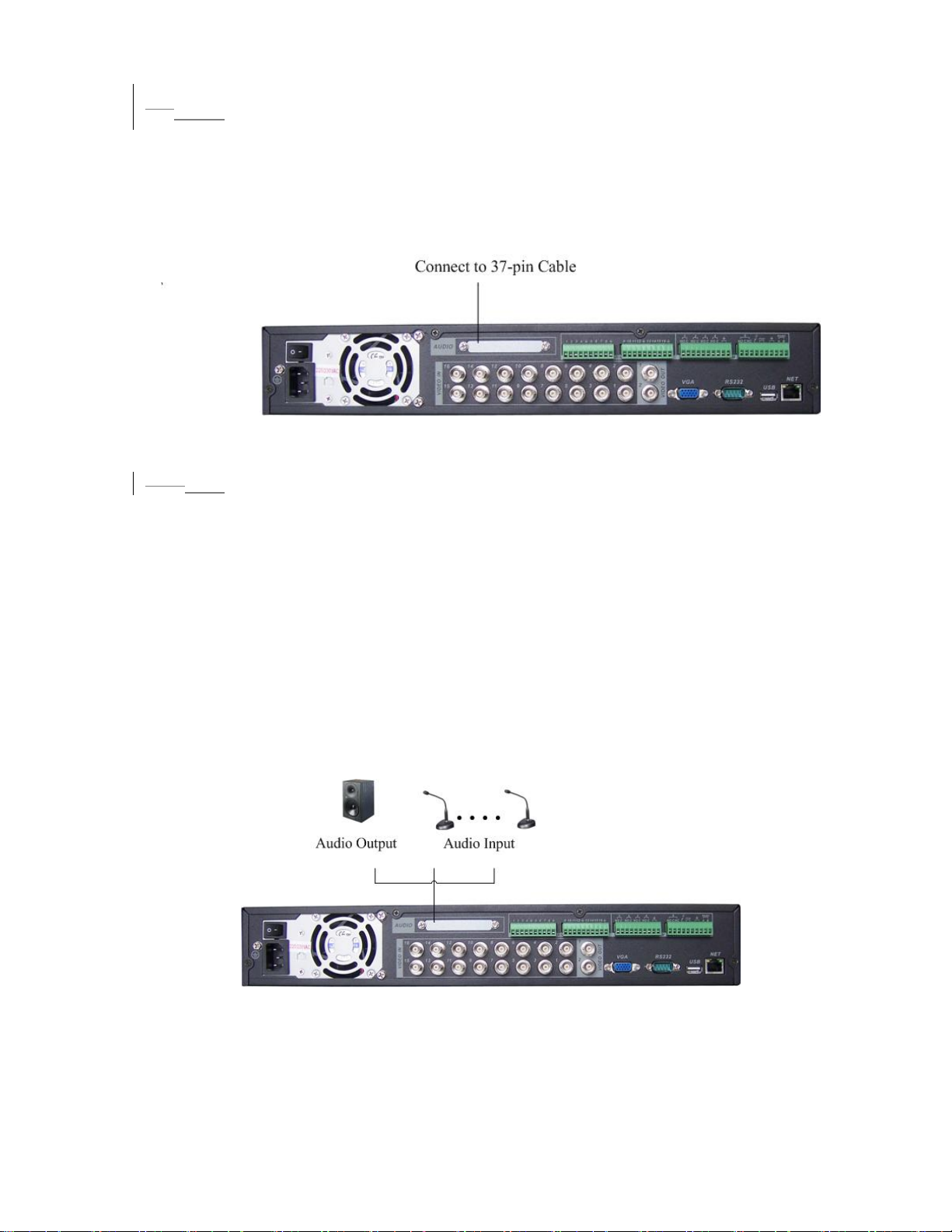
This section provides information about physically connecting video display devices
to the DVR. See
365HFigure 3-2.
If you connect the DVR with a TV monitor or VGA monitor, the DVR can automatically
detects the monitor type. And without any output device, by default, the DVR is
configured to use a TV monitor. In this case, if your application requires a VGA
monitor, you have to press the button “FN” or Shift on the front panel,or restart the
DVR.
NOTE:
Video output 1 and VGA can’t display at the same time. But Video output 2 can
display properly with Video Output 1 or VGA.
Figure 3-2
23
Page 24
2.73.7 Connecting Audio Input & Output, Bidirectional Audio, Looping
Video, Matrix
For the 25-pin or 37-pin interface, different models include different functions.
For example, DVR1604LNH-S has 4-channel audio inputs, 1 audio output, I
bidirectional audio input. See
2.7.1
3.7.1 Audio Input/One Audio Output
DVR1604LNH-S has 16 looping video inputs, 1 matrix video output, 4 audio inputs, I
bidirectional audio input, 1 audio output.
Audio input, bidirectional audio input and audio output
The DVR encodes audio and video signals simultaneously, which lets you control
audio at the monitored location.
To set up audio:
1. Make sure your audio input device matches the RCA input level. If the device and
RCA input levels do not match, audio distortion problems may occur.
2. Make sure the audio connector is wired as follows:
3. Connect a line input device or pre-amplified microphone to the audio connector for
the video channel on the rear panel.
Please refer to
367HFigure 3-4.
366HFigure 3-3.
Figure 3-3
Figure 3-4
24
Page 25
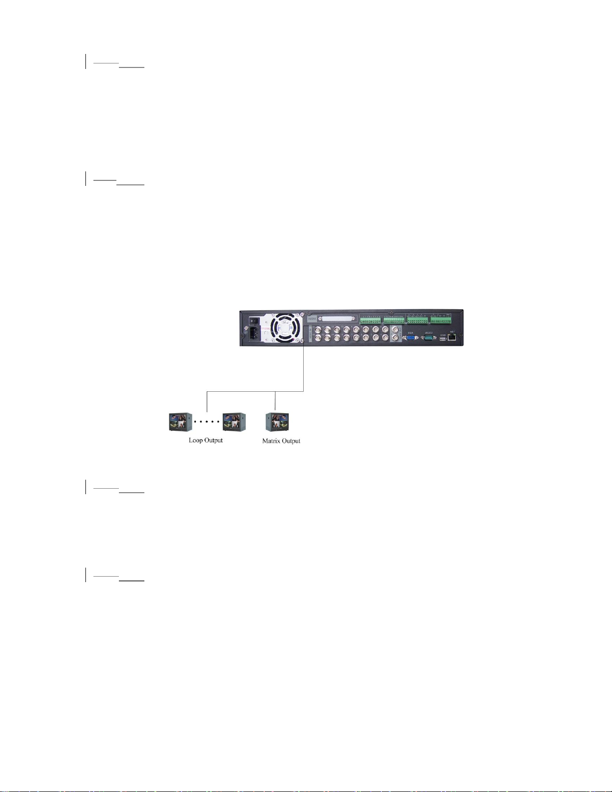
3.7.2 Looping video
2.7.2
The DVR supports looping video. It passes the video input to a monitor or other
analog video device.
To use looping video:
1. Connect a coaxial cable to the video out connector on 37-pin interface
Please note you need to use a BNC installation tool to connect coaxial cables to the
rear panel.
2. Connect the other end of the coaxial cable to the analog device.
3.7.3 Matrix Video Output
2.7.3
Use video matrix output connector during installation to display video sequentially
from each video input. The unit displays each channel for selected seconds. You can
use this feature to verify camera installation.
To display video from each connected video source:
1. Connect a video monitor to the video matrix output connector.
2. Turn the DVR on, the monitor, and each video matrix output source.
3. Verify the video from each source and troubleshoot as necessary.
Please refer to
368HFigure 3-5.
Figure 3-5
2.7.4
3.7.4 Alarm Input and Relay Output
The DVR offers 16 alarm inputs for external signaling devices, such as door contacts
or motion detectors. Each alarm input can be either normally open or normally closed.
Once configured, an alarm input can invoke many different activities, including
triggering a relay device, sending an alert to a security office or storing pre-alarm
video to the DVR.
2.7.5
3.7.5 Alarm Input
You should check your alarm input mode is grounding alarm input or not.
For this series DVR, grounding signal is needed for alarm input.
If you need to connect two units or one DVR and other device, please use relay to
separate them.
Please refer to
369HFigure 3-6 for more information.
25
Page 26
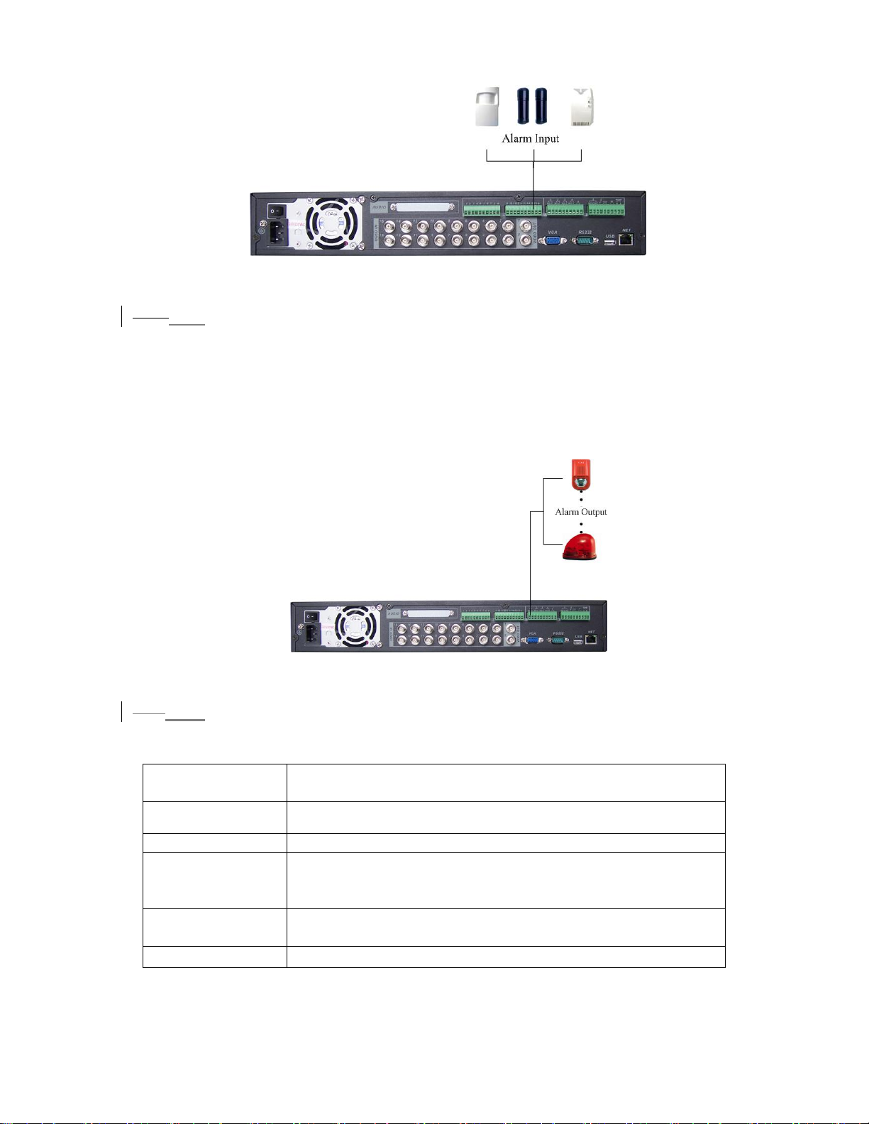
Figure 3-6
3.7.6 Alarm Output
2.7.6
Do not connect alarm output port directly with high power load (no more than 1 A) in
case of heavy current.
You can use the co-contactor to realize the connection between the alarm output port
and the load.
Please refer to
370HFigure 3-7 for more information.
Figure 3-7
3.7.7 Alarm Input and Output Details
2.7.7
You can refer to the following sheet and 371HFigure 3-8 for alarm input and output
information.
Parameter
Grounding Alarm
Ground Ground line
Alarm Input 1, 2, …, 16
Relay Output 1,2,3,4: NO and C(Normally Open and Com)
5: NO,C and NC(Normally Open, Com, Normally Closed)
6: Ctrl 12V(This is used for reset the senor)
485 A、B
485 communication port. They are used to control devices
such as PTZ.
+12(C)
This should input an external power input.
26
Page 27

Figure 3-8
Please refer to the following content for alarm input port information. See
372HFigure
3-9.
z 8/16-ch grounding alarm inputs. (Normal open or Normal close type)
z Please parallel connect COM end and GND end of the alarm detector (Provide
external power to the alarm detector).
z Please parallel connect the Ground of the DVR and the ground of the alarm
detector.
z Please connect the NC port of the alarm sensor to the DVR alarm input(ALARM)
z If you need to reset the touched-off alarm remotely, you can use DVR to supply
controllable 12 V power to the alarm detector such as the smoke detector.
z Use the same ground with that of DVR if you use external power to the alarm
device.
Figure 3-9
2.7.83.7.8 Relay Output Description
z 6 ways relay alarm output. Provide external power to external alarm device.
z To avoid over loading, please read the following relay parameters sheet carefully.
(See below table)
z The controllable +12v can be used to restore the smoke detector.
Please refer to
373HFigure 3-10 for alarm input module information.
27
Page 28
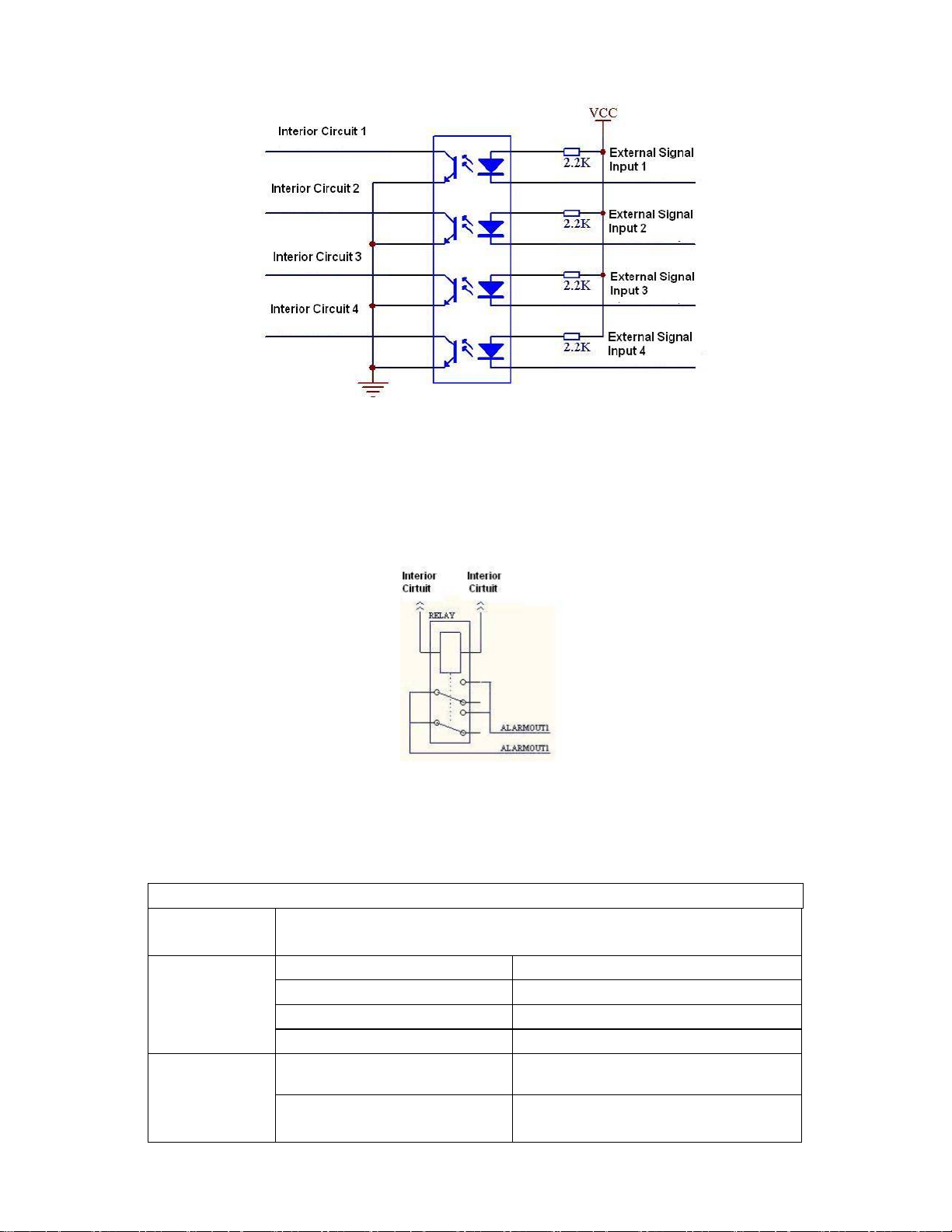
Figure 3-10
Please refer to
374HFigure 3-11 for alarm output module information.
Figure 3-11
Relay Specification
Model:
Material of
JRC-27F
Silver
the touch
Rating
(resistance
load)
Rated switch capacity 30VDC 2A, 125VAC 1A
Maximum switch power 125VA 160W
Maximum switch voltage 250VAC, 220VDC
Maximum switch currency 1A
Insulation between touches with
same polarity
between touches with
1000VAC 1minute
1000VAC 1minute
different polarity
28
Page 29
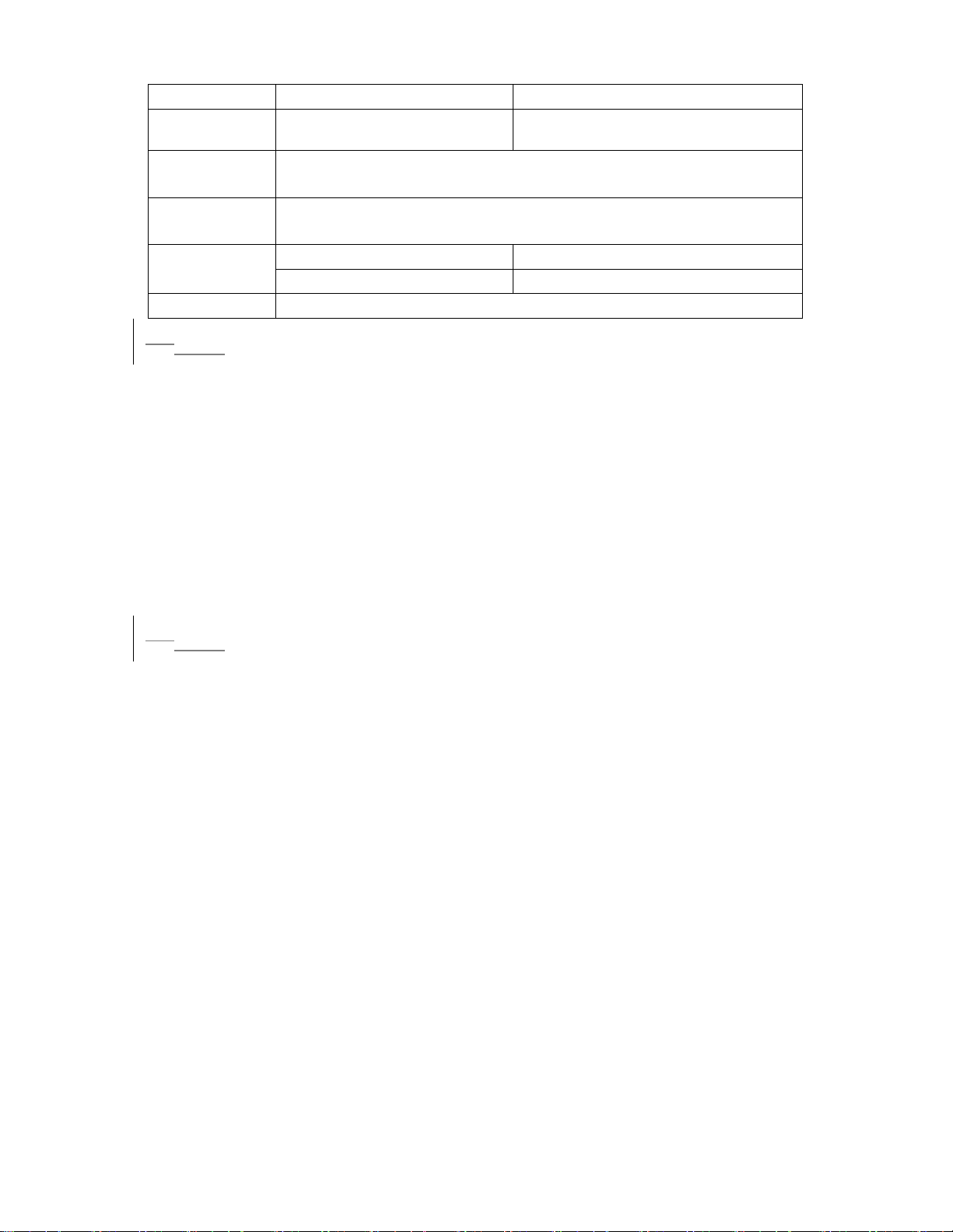
between touch and winding 1000VAC 1minute
Surge
voltage
Length of
open time
Length of
close time
Longevity
Temperature -40 ~+70
between touches with
same polarity
3ms max
3ms max
Mechanical
Electrical 200×103 MIN (0.5Hz)
1500V (10×160us)
50×106 MIN (3Hz)
2.83.8 RS232
You can connect the DVR with POS or Keyboard through RS232.
With POS system, the DVR can communicate through RS232 and network. For the
POS system, the DVR can integrate the text content and even search the record
through the info.
The series DVR also support NKB operation. You can operate the DVR from the
keyboard controls instead of using the control pad on the front panel of the unit.
To connect a NKB keyboard to the DVR:
1. Assemble the KBD keyboard according to the instructions in its accompanying
installation manual.
2. Connect the KBD keyboard into one of the RS232 ports on the DVR or through
network.
2.93.9 RS485
When the DVR receives a camera control command, it transmits that command up
the coaxial cable to the PTZ device. RS485 is a single-direction protocol; the PTZ
device can’t return any data to the unit. To enable the operation, connect the PTZ
device to the RS485(A,B) input on the DVR. Since RS485 is disabled by default for
each camera, you must enable the PTZ settings first. This series DVRs support
multiple protocols such as Pelco-D, Pelco-P.
To connect PTZ devices to the DVR:
1. Connect RS485 A,B on the DVR rear panel.
2. Connect the other end of the cable to the proper pins in the connector on the
camera.
3. Follow the instructions for configuring a camera to enable each PTZ device on the
DVR.
29
Page 30
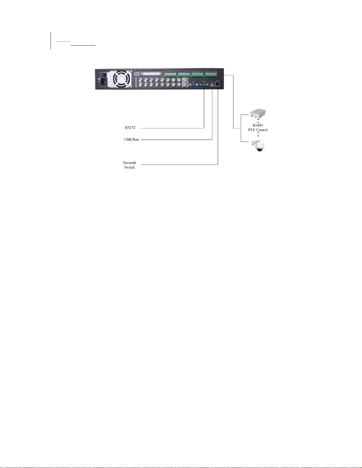
2.103.10 Other Interfaces
There are still other interfaces on the DVR, such as USB ports. You can refer to
the
375HFigure 3-12 for more information.
Figure 3-12
30
Page 31
34 Overview of Navigation and Controls
Before operation, please make sure you have properly installed HDDs and all the
cable connections.
3.14.1 Login, Logout & Main Menu
3.1.14.1.1 Login
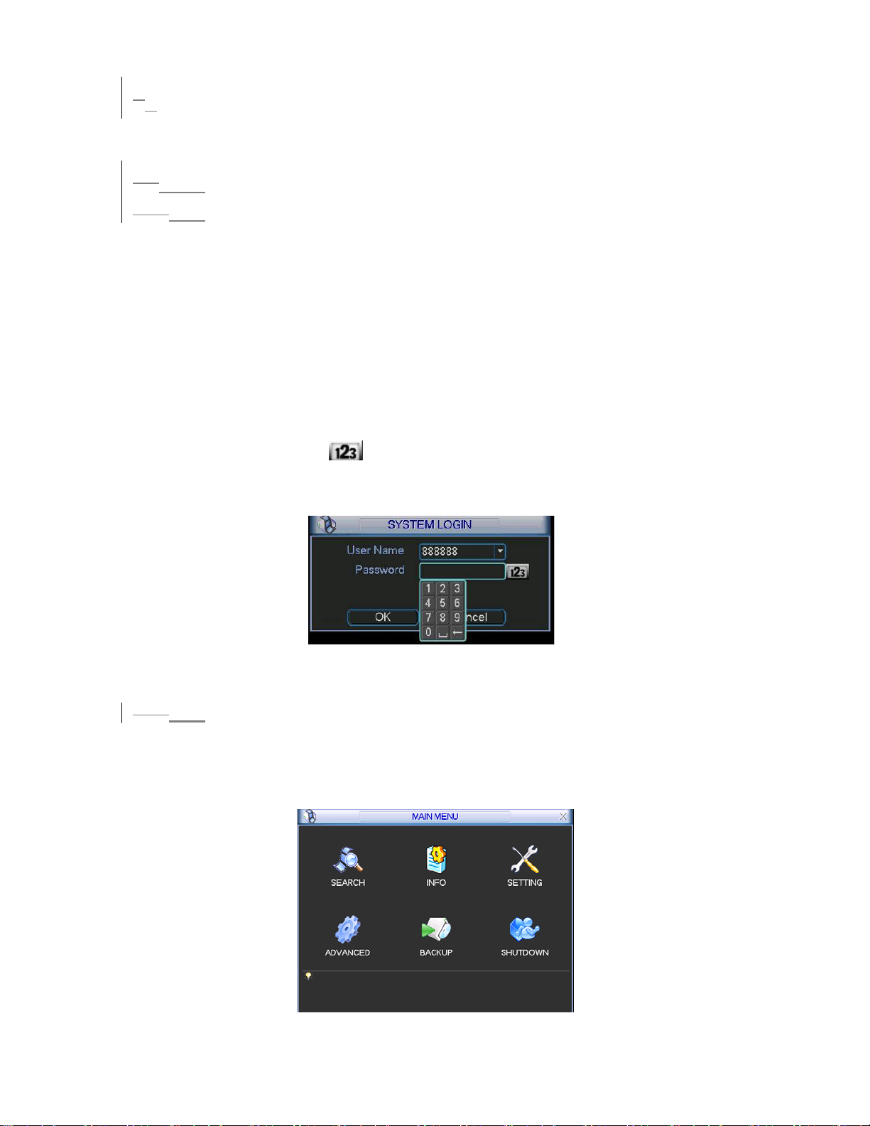
When the system boots up, default video display is in multiple-window mode.
Click Enter or left click mouse, you can see the login interface. See
System consists of four accounts:
z Username: admin. Password: admin. (administrator, local and network)
z Username: 888888. Password: 888888. (administrator, local only)
z Username: 666666. Passwords: 666666(Lower authority user who can only
monitor, playback, backup and etc.)
z Username: default. Password: default(hidden user)
For your system security, please modify you password after first login.
You can use USB mouse, front panel, remote controller or keyboard to input.
About input method: Click to switch between numeral, English character
376HFigure 4-1.
(small/capitalized) and denotation.
Note: 3 times login failure within 30 minutes will result in account lock!
Figure 4-1
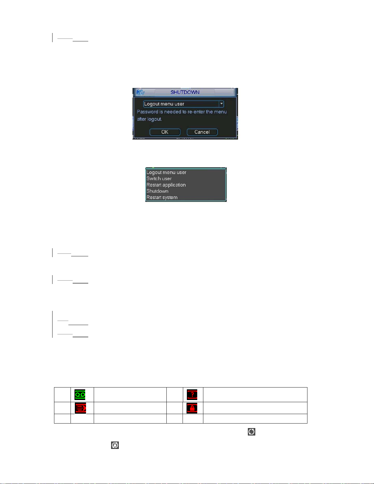
4.1.2 Main Menu
3.1.2
When you login, the system main menu is shown as below. See 377HFigure 4-2.
There are total six icons: search, information, setting, backup, advanced and
shutdown. Move the cursor to highlight the icon, then double click mouse to enter
the sub-menu.
Figure 4-2
31
Page 32
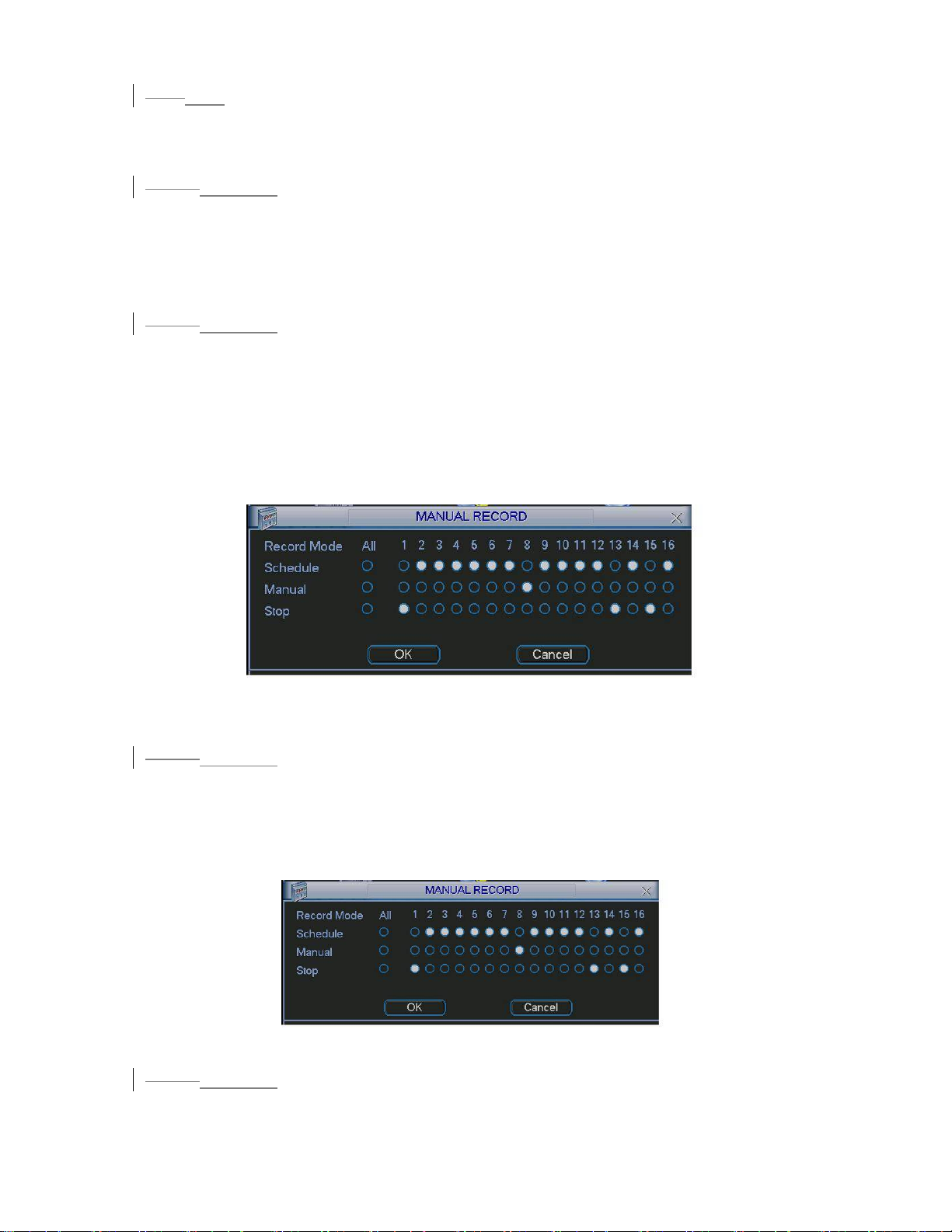
3.1.34.1.3 Logout
There are two ways for you to log out.
One is from menu option:
In the main menu, click shutdown button, you can see an interface is shown as
378H
below. See
Figure 4-3.
Figure 4-3
379H
There are several options for you. See
Figure 4-4.
Figure 4-4
The other way is to press power button on the front panel for at least 3 seconds,
system will stop all operations. Then you can click the power button in the rear
panel to turn off the DVR.
3.1.4
4.1.4 Auto Resume after Power Failure
The system can automatically backup video and resume previous working status
after power failure.
4.1.5 Replace Button Battery
3.1.5
Please make sure to use the same battery model if possible.
We recommend replace battery regularly (such as one-year) to guarantee system
time accuracy.
3.24.2 Recording Operation
3.2.14.2.1 Live Viewing
When you login, the system is in live viewing mode. You can see system date,
time and channel name. If you want to change system date and time, you can
refer to general settings (Main Menu->Setting->General). If you want to change
the channel name, please refer to the display settings (Main Menu->Setting>Display)
1
2
Recording status
Motion detection 4 Camera lock
3
Video loss
Note: Please refer to the following sheet for channel status. stands for opening
switch function, stands for closing switch function.
Page 33
4.2.2 Manual record
3.2.2
Note:
You need to have proper rights to implement the following operations. Please
make sure the HDDs have been properly installed.
3.2.2.1
4.2.2.1 Manual record menu
There are two ways for you to go to manual record menu.
z Right click mouse or in the main menu, Advanced->Manual Record.
z In live viewing mode, click record button in the front panel or record button in the
remote control.
Manual record menu is shown as in
3.2.2.2
4.2.2.2 Basic operation
380HFigure 4-5.
There are three statuses: schedule/manual/stop. Highlight icon“○” to select
corresponding channel.
z Manual: the highest priority. After manual setup, all selected channels will begin
ordinary recording.
z Schedule: channel records as you have set in recording setup (Main Menu-
>Setting->Schedule)
z Stop: all channels stop recording.
Figure 4-5
3.2.2.3
4.2.2.3 Enable/disable record
Please check current channel status: “○” means it is not in recording status,
“●” means it is in recording status.
You can use mouse or direction key to highlight channel number. See
381HFigure 4-6.
Figure 4-6
3.2.2.4
4.2.2.4 Enable all channel recording
Highlight ○ below All, you can enable all channel recording.
z All channel schedule record
33
Page 34
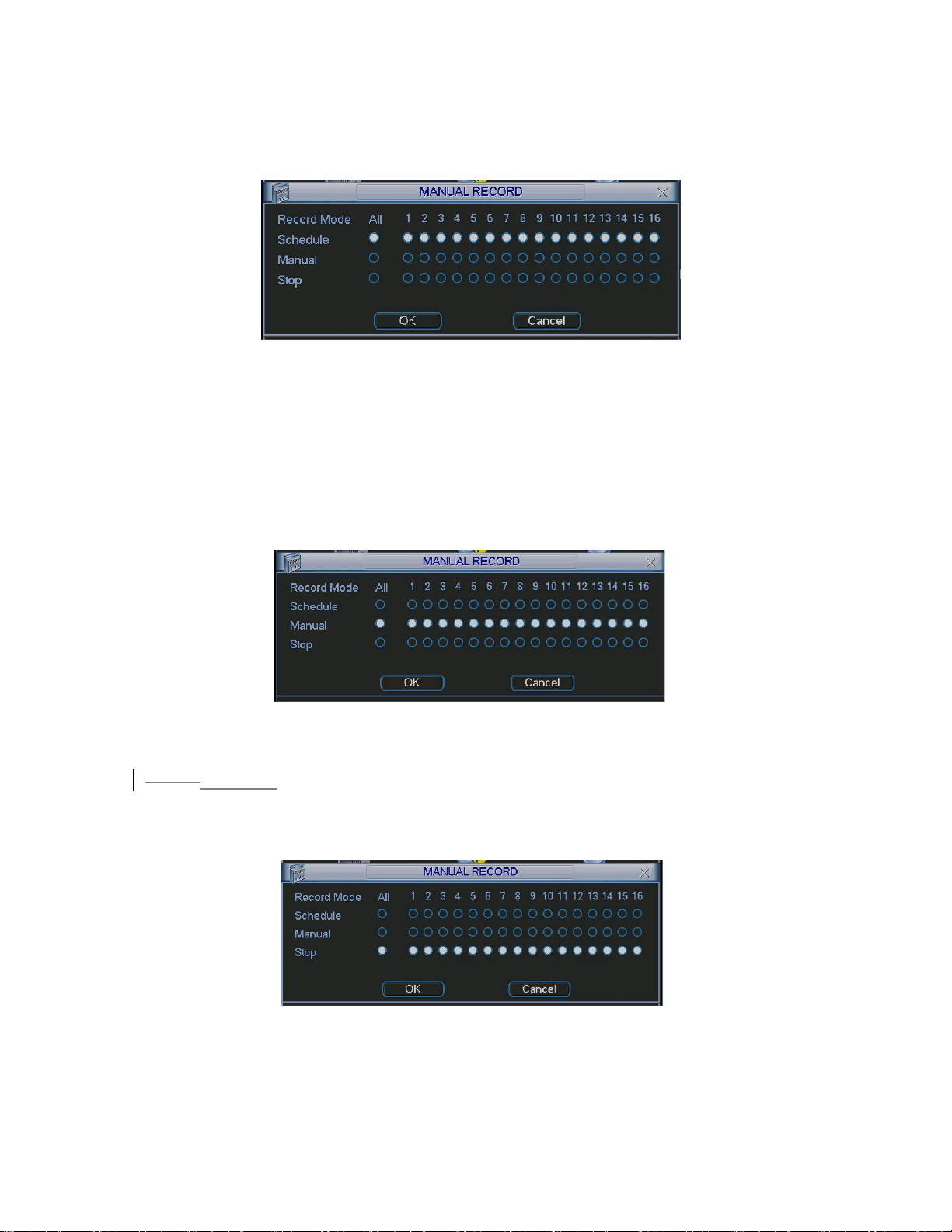
Please highlight “ALL” after “Schedule”. See
382HFigure 4-7.
When system is in schedule recording, all channels will records as you have
previously set (Main menu->Setting->Schedule).
The corresponding indication light in front panel will turn on.
Figure 4-7
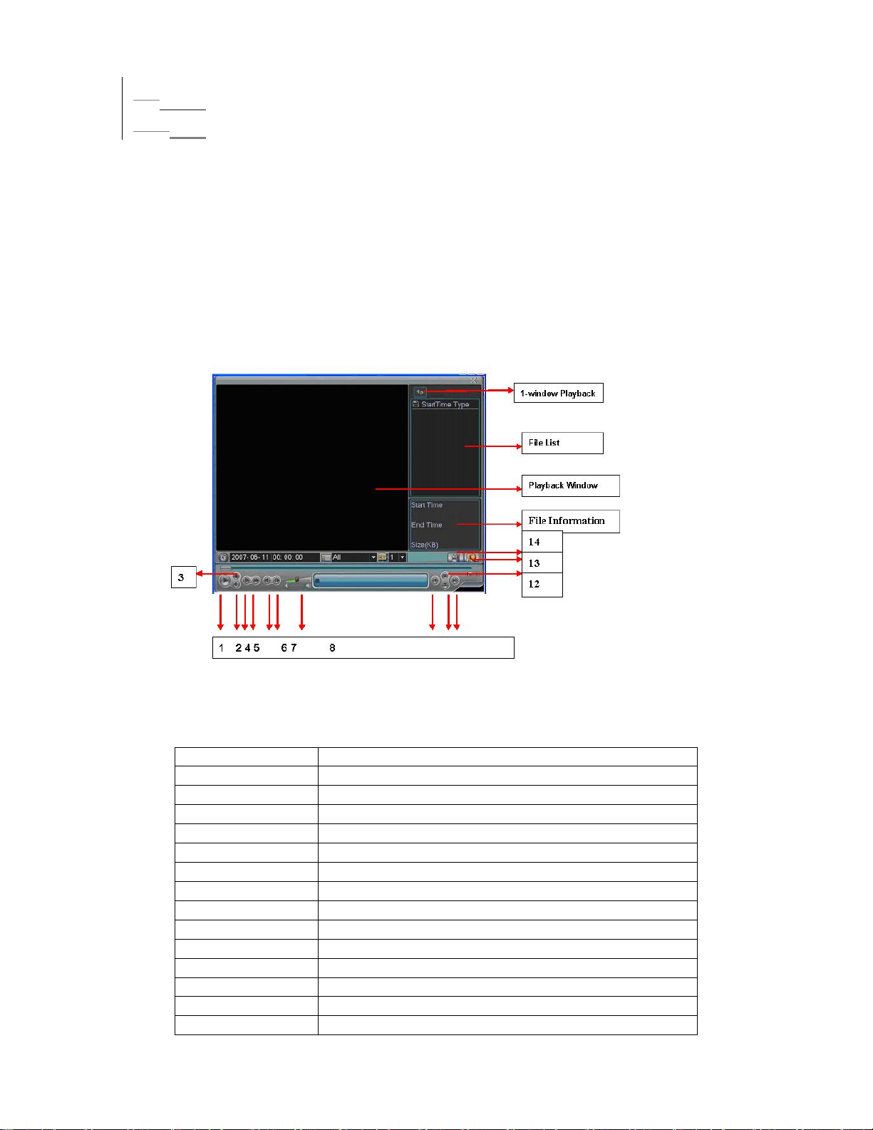
z All channel manual record
Please highlight “ALL” after “Manual.” See
383HFigure 4-8.
When system is in manual recording, all scheduled set up you have set in will be
null ((Main menu->Setting->Schedule)).
You can see indication light in front panel turns on, system begins manual record
now.
Figure 4-8
3.2.2.5
4.2.2.5 Stop all channel recording
Please highlight “ALL” after “Stop”. See 384HFigure 4-9.
System stops all channel recording no matter what mode you have set in the
menu (Main menu->Setting->Schedule)
Figure 4-9
34
Page 35
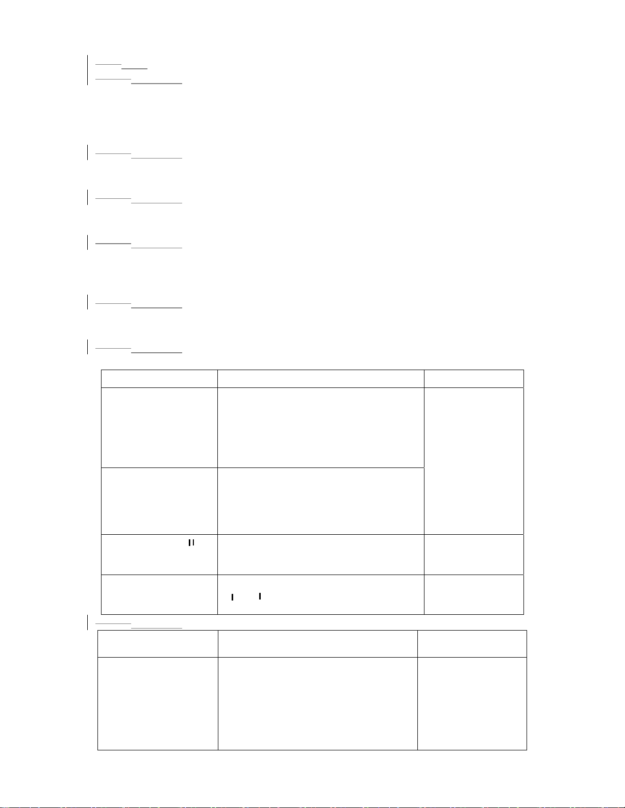
3.34.3 Search & Playback
3.3.14.3.1 Search Menu
There are two ways for you to go to search menu.
z Click Pause/Play button in the remote control.
z Click search in the main menu.
Search interface is shown as below. See
Usually there are three file types:
z R: regular recording file.
z A: external alarm recording file.
z M: motion detection recording file
z C: card and pos test overlay recording file(For some special series only)
There are several playback windows. This System supports 1-ch playback.
385HFigure 4-10.
Figure 4-10
Please refer to the following sheet for more information.
Serial Number Function
1 Play
2 Backward
3 Stop
4 Slow play
5 Fast play
6 Previous frame
7 Next frame
8 Volume
9 Previous file
10 Next channel
11 Next file
12 Previous channel
13 Search
14 Backup
35
Page 36
4.3.2 Basic Operation
3.3.2
3.3.2.14.3.2.1 Playback
There are various search modes: video type, channel number or time. The system
can max display 32 files in one screen. You can use up/down button to turn page.
Select the file name and double click mouse (or click enter button), you can view
file content.
3.3.2.2
4.3.2.2 Accurate playback
Input time (h/m/s) in the time column and then click playback button, system can
operate accurate playback.
3.3.2.3
4.3.2.3 Synchronized playback function when playback
During playback process, click numeral key, system can switch to the
corresponding channel video of the same time.
3.3.2.4
4.3.2.4 Digital zoom
When the system is in full-screen playback mode, drag your mouse in the screen
to select a section and then left click mouse to realize digital zoom. You can right
click mouse to exit.
3.3.2.5
4.3.2.5 File backup
System supports backup operation during search. You can draw a √ before file
name (multiple choices). Then click backup button (Button 14 in
3.3.2.6
4.3.2.6 Slow playback and fast playback
386HFigure 4-10).
Please refer to the following sheet for slow play and fast playback function.
Button Illustration Remarks
Fast play button In playback mode, click this button to
switch between various fast play
modes such as fast play 1,fast play
2 and more.(Fast play 1 means fast
Frame rate may
vary due to
different
versions.
play level 1 or not about speed)
Slow play button ►
(Or you can turn
the outer ring
counter clockwise.)
3、Play/Pause►
In playback mode, click this button to
switch between various slow play
modes such as slow play 1 or slow
play 2.
In slow playback mode, click this
button to switch between play/pause
modes.
4、Previous/next
In playback mode, you can click _
and ` to view previous or next
video in current channel.
3.3.2.74.3.2.7 Fast forward/fast backward and frame by frame playback
Special Functions
of Shuttle and Jog
Fast forward(outer
ring clockwise)
Illustration Remarks
When playback, turn the shuttle
(outer ring) clockwise one round:
you can view in fast level 1
Turn it two rounds you get fast
level 2. You can continue turning
to get different speed.
In forward or
backward mode,
double click
Pause/Play button
to get normal
playback.
36
Page 37
Fast backward(outer
ring counter
clockwise)
When playback, turn the shuttle
(outer ring) counter clock-wise one
round, you can view in backward
Frame rate may
vary due to
different version.
level 1. Turn it two rounds, you get
backward level 2. You can continue
turning to get different speed.
Manual playback
frame by frame
In playback mode, click play/pause
button, slowly turn the jog (inner
dial) clock-wise to view frame by
frame, counter clock wise to view I
frame playback.
3.3.2.84.3.2.8 Backward playback and frame by frame playback
Button Illustration Remarks
Backward play
_ in playback
interface.
Manual
playback frame
by frame.
In normal playback mode, left click
backward play button, system begins
backward playback.
Double click backward play button
again, system goes to pause mode.
Click pause button in normal playback
mode, slowly turn the jog (inner dial)
clock-wise to view frame by frame,
When system is in
backward play or
frame by frame
playback mode,
you can click play
button to go to
normal playback.
counter clock wise to view I frame
playback.
Note:
All the operations here (such as playback speed, channel, time and progress)
have relationship with hardware version. Some series DVRs do not support some
functions or playback speeds.
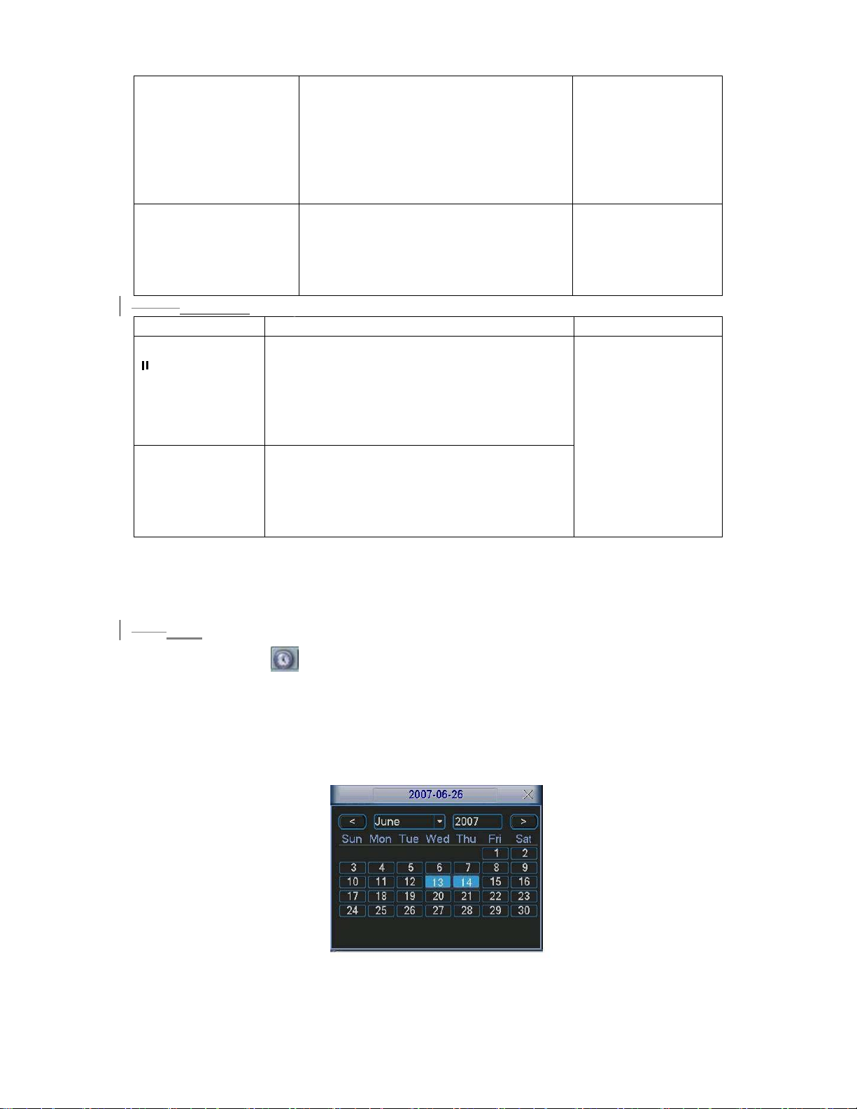
4.3.3 Calendar
3.3.3
Click calendar icon in
387H
Figure 4-10, system pops up calendar for your
reference.
Highlighted date means that there are record files in that day. You can click blue
date to view file list.
388H
Figure 4-11, there are video files in March 13th and 14th. Double click date to
In
view file list.
Figure 4-11
Page 38
3.44.4 Record Setup (Schedule)
When the system boots up, it is in default 24-hour regular mode. You can set
record type and time in schedule interface.
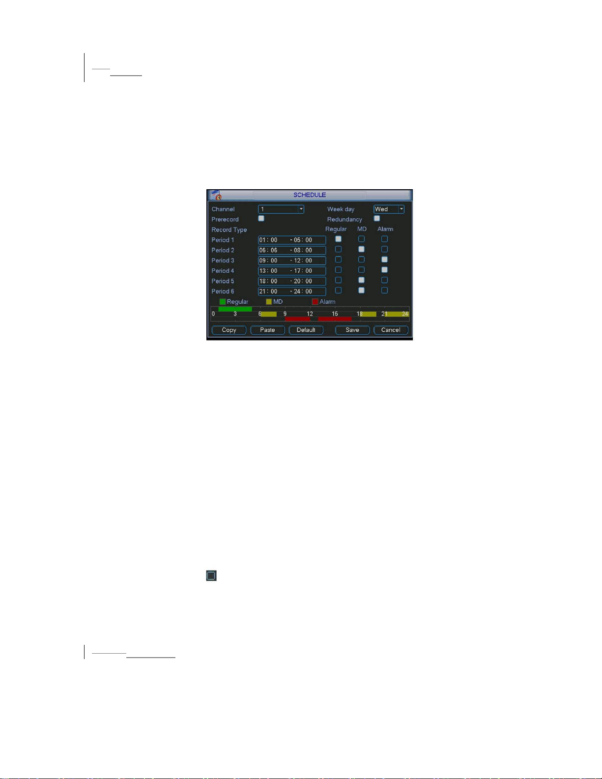
4.4.1 Schedule Menu
In the main menu, from setting to schedule, you can go to schedule menu.
See
389HFigure 4-12.
There are three record types: R-Regular, MD-Motion detection, A- Alarm. In
some series, system also supports C-Card)
Figure 4-12
4.4.2 Basic Operation
There are totally six periods. See
390HFigure 4-12.
z Channel: Please select the channel number first. You can select “all” if you want
to set for the whole channels.
z Week day: There are eight options: ranges from Saturday to Sunday and all.
z Redundancy: System supports redundancy backup function. You can highlight
Redundancy button to activate this function. Please note, before enable this
function, please set at least one HDD as redundant. Refer to the manual for
detailed information.
z Prerecord: System supports prerecord function. The previous one to three
seconds video before alarm occurs can be included in recorded video.
z Record types: There are three types: regular, motion detection (MD) and Alarm.
Please highlight icon to select the corresponding function. After all the setups
please click save button, system goes back to the previous menu.
At the bottom of the menu, there is a color bar for your reference. Green stands
for regular recording, yellow stands for motion detection and red stands for alarm
recording.
3.4.1.1
4.4.1.1 Quick Setup
This function allows you to copy one channel setup to another. After setting in
channel 1, you can click paste button and turn to channel 2 and then click copy
button. You can finish setting for one channel and then click save button or you
can finish all setup and then click save button to memorize all the settings.
38
Page 39
3.4.1.2
4.4.1.2 Redundancy
Redundancy function allows you to memorize record file in several disks. These
files are created, packaged and closed simultaneously. When there is file
damage occurred in one disk, there is a spare one in the other disk. You can use
this function to maintain data reliability and safety.
In the main menu, from Setting to Schedule, you can highlight redundancy button
to enable this function. See
391HFigure 4-12.
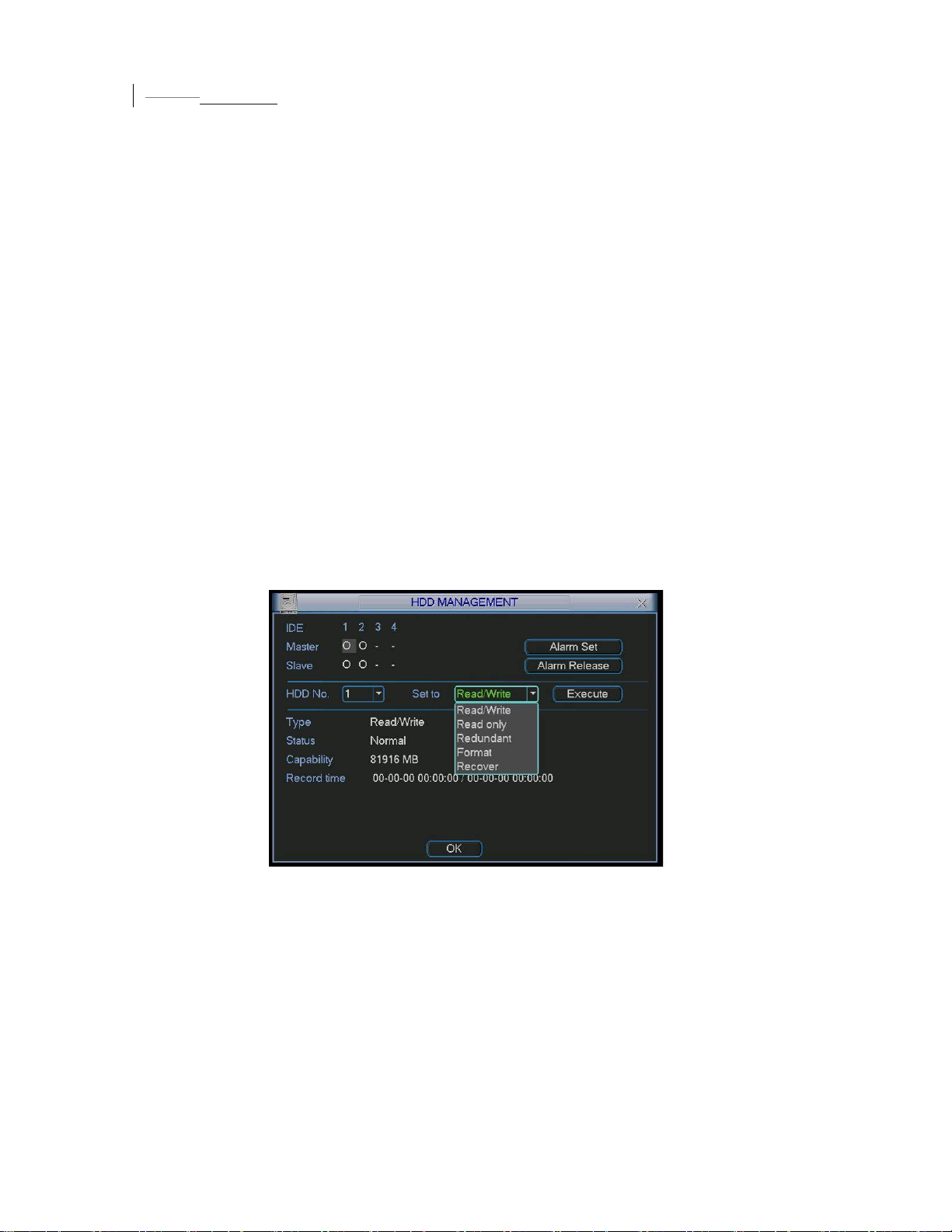
In the main menu, from Advanced to HDD management, you can set one or more
disk(s) as redundant. You can select from the dropdown list. See
392HFigure 4-13.
System auto overwrites old files once hard disk is full.
Please note only read/write disk or read-only disk can backup file and support file
search function, so you need to set at least one read-write disk otherwise you can
not record video.
Note:
About redundancy setup please note:
z If current channel is not recording, current setup gets activated when the channel
begin recording the next time.
z If current channel is recording now, current setup will get activated right away, the
current file will be packet and form a file, then system begins recording as you
have just set.
After all the setups please click save button, system goes back to the previous
menu.
Figure 4-13
Playback or search in the redundant disk.
There are two ways for you to playback or search in the redundant disk.
z Set redundant disk(s) as read-only disk or read-write disk (Main menu-
>Advanced->HDD management). See
393HFigure 4-13.System needs to reboot to get
setup activated. Now you can search or playback file in redundant disk.
z Dismantle the disk and play it in another PC.
39
Page 40
3.54.5 Motion Detect
4.5.1 Go to Motion Detect Menu
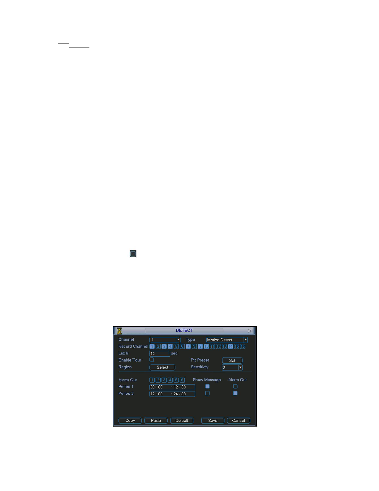
In the main menu, from Setting to Detect, you can see motion detect interface.
394HFigure 4-14.
See
4.5.2 Motion Detect
Detection menu is shown as below. See
z Channel: select the channel you want to implement motion detection.
z Type: in the dropdown list, select motion detection item.
z Record channel: select the channel to activate recording function once alarm
occurred. Please make sure you have set MD record in encode interface(Main
Menu->Setting->Schedule) and schedule record in manual record interface(Main
Menu->Advanced->Manual Record)
z Enable tour: Here is for you to activate tour between different cameras.
z Latch: when motion detection complete, system auto delays detecting for a
specified time. The value ranges from 10-300(Unit: second)
z PTZ preset: Click set button, the interface is shown as in
can set preset for one or more channels.
z Region: click “select” button to set motion detection region. See
z Sensitivity: there are six levels. The six-level is of the highest sensitivity.
z Alarm output: when alarm occurred, system enables peripheral alarm devices.
z Show message: System pops up message in the screen to alert you once alarm
occurred.
395HFigure 4-14.
396HFigure 4-15.Here you
397HFigure 4-16.
Please highlight icon to select the corresponding function.
After all the setups
please click save button, system goes back to the previous menu.
Note:
In motion detection mode, you can not use copy/paste to set channel setup since the
video in each channel may not be the same.
In
398HFigure 4-15, you can left click mouse and then drag it to set a region for motion
detection. Click Fn to switch between deployment and withdraw motion detection.
After setting, click enter button to exit.
Figure 4-14
40
Page 41
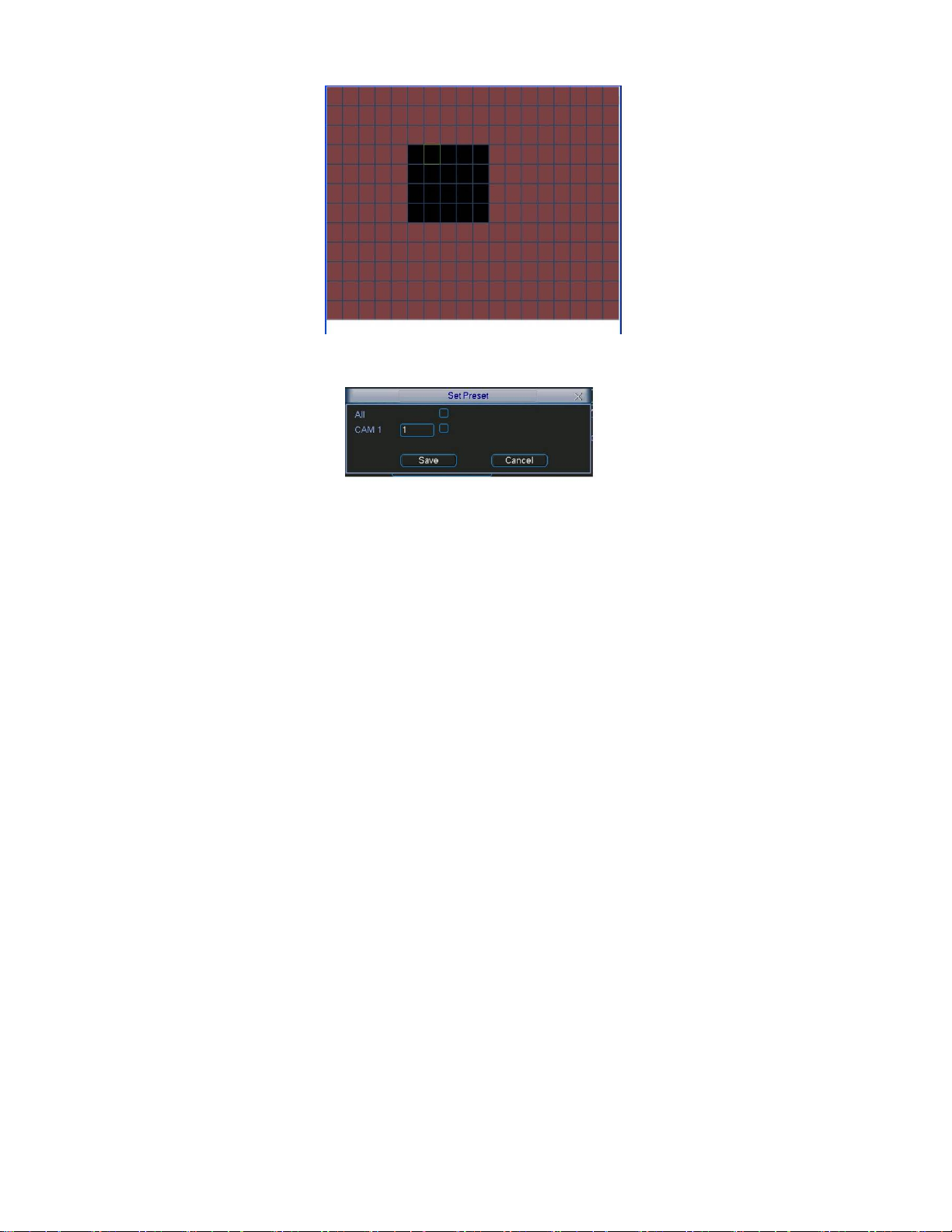
Figure 4-15
Figure 4-16
4.5.3 Video Loss
399HFigure 4-14, select video loss in the Type item. You can see the interface is
In
shown as in
400HFigure 4-17.This function allows you to be informed when video loss
phenomenon occurred. You can enable alarm output channel and then enable
show message function.
z Channel: select the channel you want to enable lens shading alarm.
z Type: please select video loss.
z Record channel: select the channel to record when video loss occurred.
z Alarm output: activate peripheral alarm device when video loss occurred.
z Enable tour: Here is for you to activate tour between different cameras.
z Latch: when motion detection completes, system auto delays detecting for a
specified time. The value ranges from 10-300(Unit: second)
z PTZ preset: Click set button to set preset for one or all channels. See
401HFigure 4-16.
z Period 1/2: It is for you to set two periods (00.00-24.00).
z Alarm output: when video loss occurred, system enables peripheral alarm devices.
Please highlight icon to enable this function
z Show message: System pops up message in the screen to alert you once alarm
occurred. Please highlight icon to enable this function.
41
Page 42
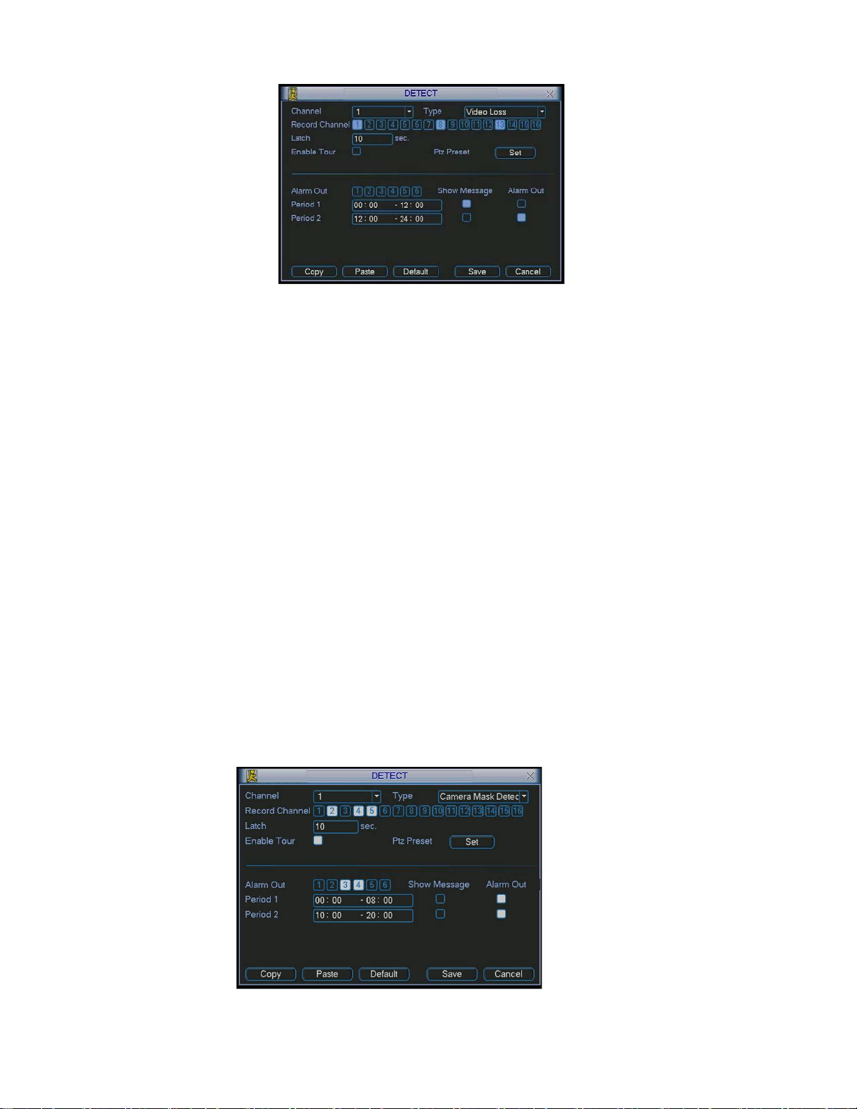
Figure 4-17
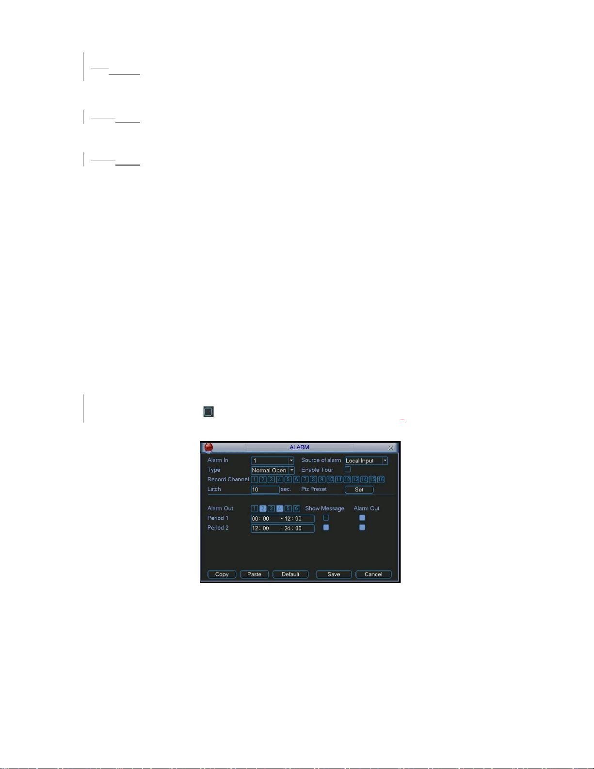
4.5.4 Camera Mask Detect
When someone viciously masks lens, the system can alert you to guarantee video
continuity. Camera mask detection interface is shown as in
402HFigure 4-18.
z Channel: select the channel you want to enable camera mask detection function.
z Type: please select camera mask detect from the dropdown list.
z Record channel: select the channel to record when camera mask occurred.
z Alarm output: activate peripheral alarm device when camera mask occurred.
z Enable tour: Here is for you to activate tour between different cameras.
z Latch: when motion detection completes, system auto delays detecting for a
specified time. The value ranges from 10-300(Unit: second)
z PTZ preset: Click set button to set preset for one or all channels. See
403HFigure 4-16.
z Period 1/2: there are for you to set two periods (00.00-24.00).
z Alarm output: when camera masking occurred, system enables peripheral alarm
devices. Please highlight icon to enable this function
z Show message: System pops up message in the screen to alert you once alarm
occurred. Please highlight icon to enable this function
Note:
In this interface, copy/paste function is only valid for the same type, which means
you can not copy a channel setup in video loss mode to camera mask detect
mode.
Figure 4-18
42
Page 43
3.64.6 Alarm Setup and Alarm Activation
Before operation, please make sure you have properly connected alarm devices
such as buzzer.
3.6.1
4.6.1 Go to alarm setup interface
In the main menu, from Setting to Alarm, you can see alarm setup interface.
404HFigure 4-19.
See
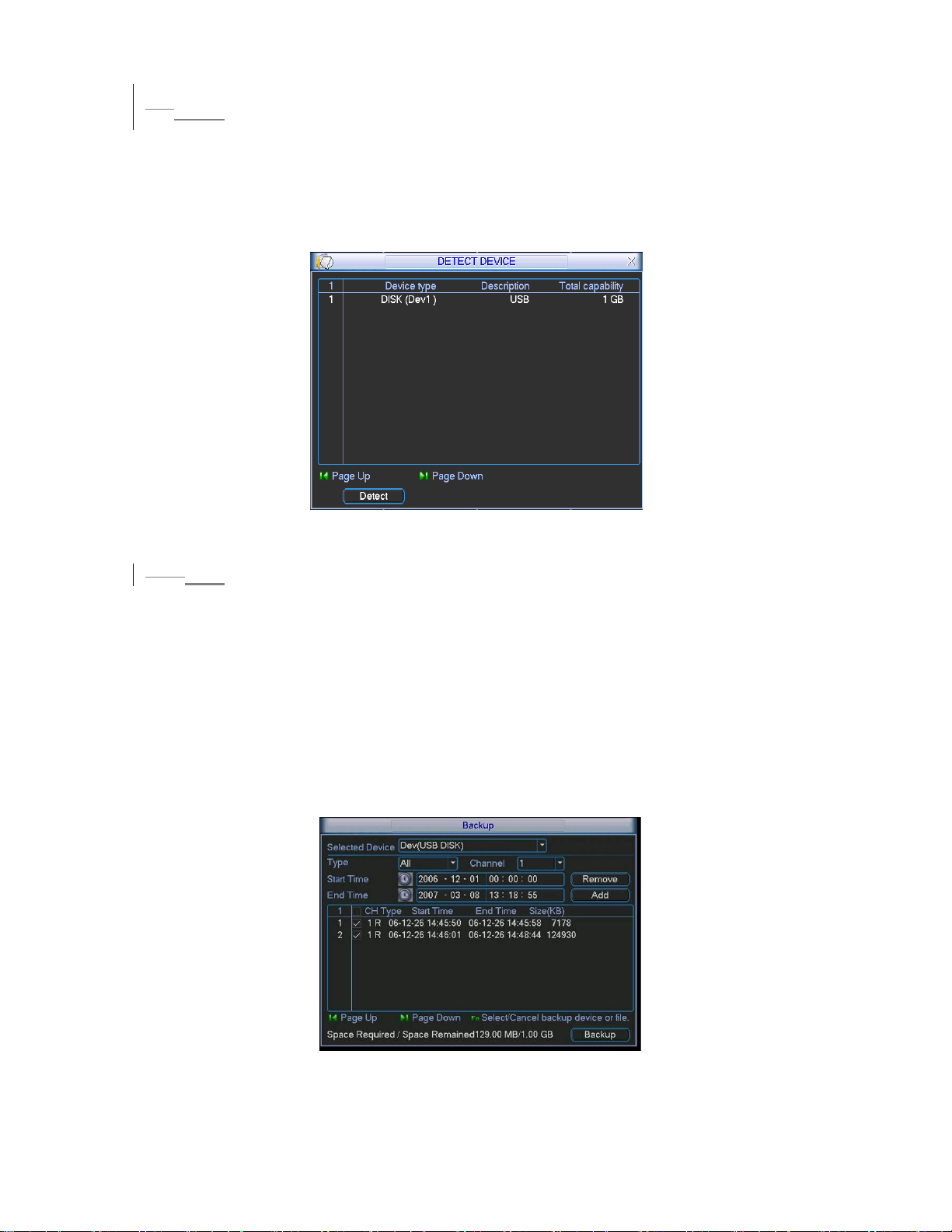
4.6.2 Alarm setup
3.6.2
Alarm interface is shown as below. See 405HFigure 4-19.
z Alarm in: here is for you to set channel number.
z Source of alarm: there are two alarm sources: local input or network input.
z Type: normal open or normal close.
z Record channel: you can select proper channel to record alarm video (Multiple
choices). At the same time you need to set alarm record in schedule interface
(Main Menu->Setting->Schedule) and select schedule record in manual record
interface (Main Menu->Advance->Manual Record).
z Latch: Here is for you to set proper delay duration. Value ranges from 10 to 300
seconds. System automatically delays specified seconds in turning off alarm and
activated output after external alarm cancelled.
z PTZ preset: Here is for you to activate PTZ control.
z Relay out: select proper alarm activation output channel (multiple choices).
z Show message: System pops up message in the screen to alert you once alarm
occurred.
z Period 1 and period 2: set proper time and alarm tips.
Please highlight icon to select the corresponding function.
After all the setups
please click save button, system goes back to the previous menu.
Figure 4-19
43
Page 44
3.74.7 Backup
Click backup icon in the main menu, there are two function items: detect device
and backup files.
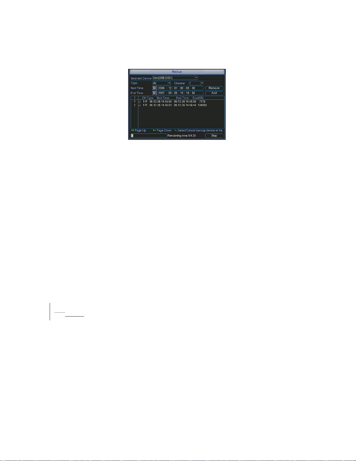
4.7.1 Detect Device
Here is for you to view devices information. See
406HFigure 4-20.
Figure 4-20
3.7.1
4.7.1 Backup
Select backup device and then channel, file start time and end time.
Click add button, system begins search. All matched files are listed below.
System automatically calculates the capacity needed and remained. See
407HFigure
4-21.
system only backup files with a √ before channel name. You can use Fn or
cancel button to delete after file serial number.
Click backup button, you can backup selected files. There is a process bar for you
reference.
When the system completes backup, you can see a dialogue box prompting
successful backup.
Figure 4-21
44
Page 45
Click backup button, system begins burning. At the same time, the backup button
becomes stop button. You can view the remaining time and process bar at the left
bottom. See
408HFigure 4-22.
Figure 4-22
Tips:
During backup process, you can click ESC to exit current interface; but the
system will not terminate backup process.
Note:
When you click stop button during the burning process, there are two conditions
for different devices:
z For CD/DVD burner device, the stop function becomes activated immediately and
there is no data in the burner.
z For USB device, system can backup the data before you click stop button. For
example, if there is a file of 10 minutes, when you click stop after five minutes
backup, system only save the previous 5-minute data in the device.
The file name format usually is: SN_CH+channel number+time Y+M+D+H+M+S.
In the file name, the YDM format is the same as you set in general interface.
(Main Menu ->Setting ->General).You can visit our website to view listed CDROM type.
3.84.8 PTZ Control and Color Setup
Note: All the operation here is based on DH-SD protocol. For PELCO protocols,
there might be a little difference.
4.8.1 Cable Connection
Please follow the procedures below to go on cable connection
z Connect the dome RS485 port to DVR 485 port..
z Connect dome video output cable to DVR video input port.
z Connect power adapter to the dome.
4.8.2 PTZ Setup
Note: The camera video should be in the current screen. Before setup, please
check the following connections are right:
z PTZ and decoder connection is right. Decoder address setup is right.
z Decoder A (B) line connects with DVR A (B) line.
45
Page 46
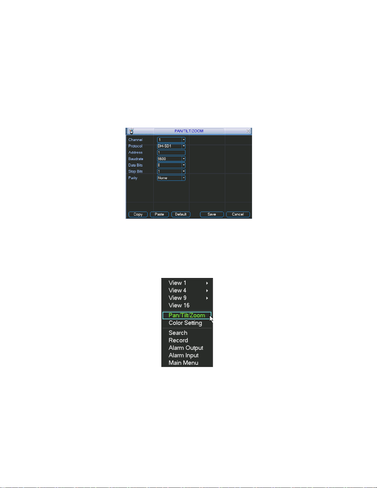
Boot up the DVR, input user name and password.
In the main menu, click setting, and then click Pan/Tilt Control button. The
interface is shown as in
409HFigure 4-23. Here you can set the following items:
z Channel: select the current camera channel.
z Protocol: select corresponding PTZ protocol(such as DH-SD1)
z Address: default address is 1.
z Baud rate: select corresponding baud rate. Default value is 9600.
z Data bits: select corresponding data bits. Default value is 8.
z Stop bits: select corresponding stop bits. Default value is 1.
z Parity: there are three options: odd/even/none. Default setup is none.
Figure 4-23
After all the setting please click save button.
In one window display mode, right click mouse (click “Fn” Button in the front panel
or click “Fn” key in the remote control). The interface is shown as in
410HFigure 4-24.
Figure 4-24
Click Pan/Tilt/Zoom, the interface is shown as below. See
Here you can set the following items:
z Step: value ranges fro 1 to 8.
z Zoom
z Focus
z Iris
411HFigure 4-25.
46
Page 47
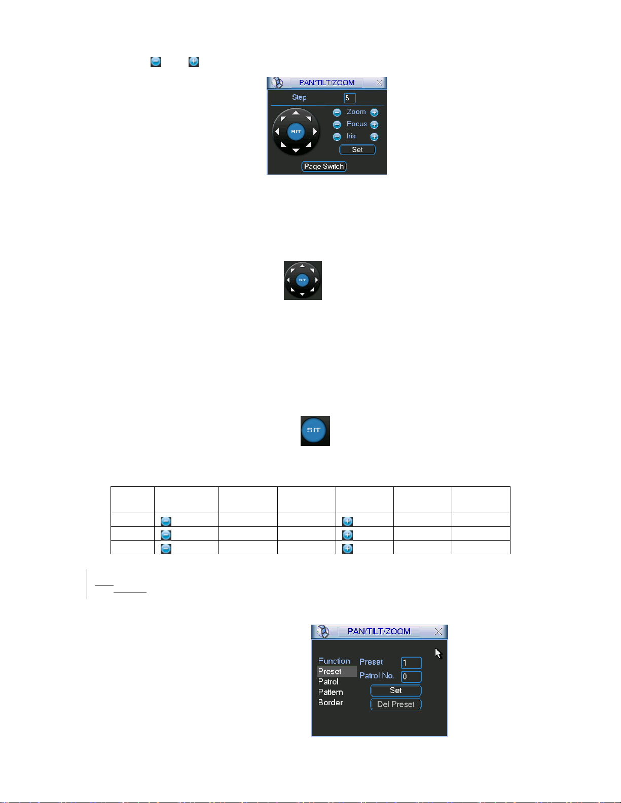
Click icon and to adjust zoom, focus and iris.
Figure 4-25
In
412HFigure 4-25, please click direction arrows (See 413HFigure 4-26) to adjust PTZ position.
There are totally 8 direction arrows.
Figure 4-26
4.8.3 3D Intelligent Positioning Key
In the middle of the eight direction arrows, there is a 3D intelligent positioning key.
See
414HFigure 4-27.
Click this key, system goes back to the single screen mode. Drag the mouse in the
screen to adjust section size. It can realize PTZ automatically.
Figure 4-27
Here is a sheet for you reference.
Name Function
key
Zoom
Focus
Iris
function Shortcut
key
Near Far
Near
close
_
W
Function
key
function Shortcut
Key
Far
Open
f
3.94.9 Preset/ Patrol/Pattern/Scan
In 415HFigure 4-25, click the “set” button. The interface is shown as below. See 416HFigure
4-28.
Here you can set the following items:
z Preset
z Patrol(Tour)
z Pattern
z Border
Figure 4-28
47
Page 48
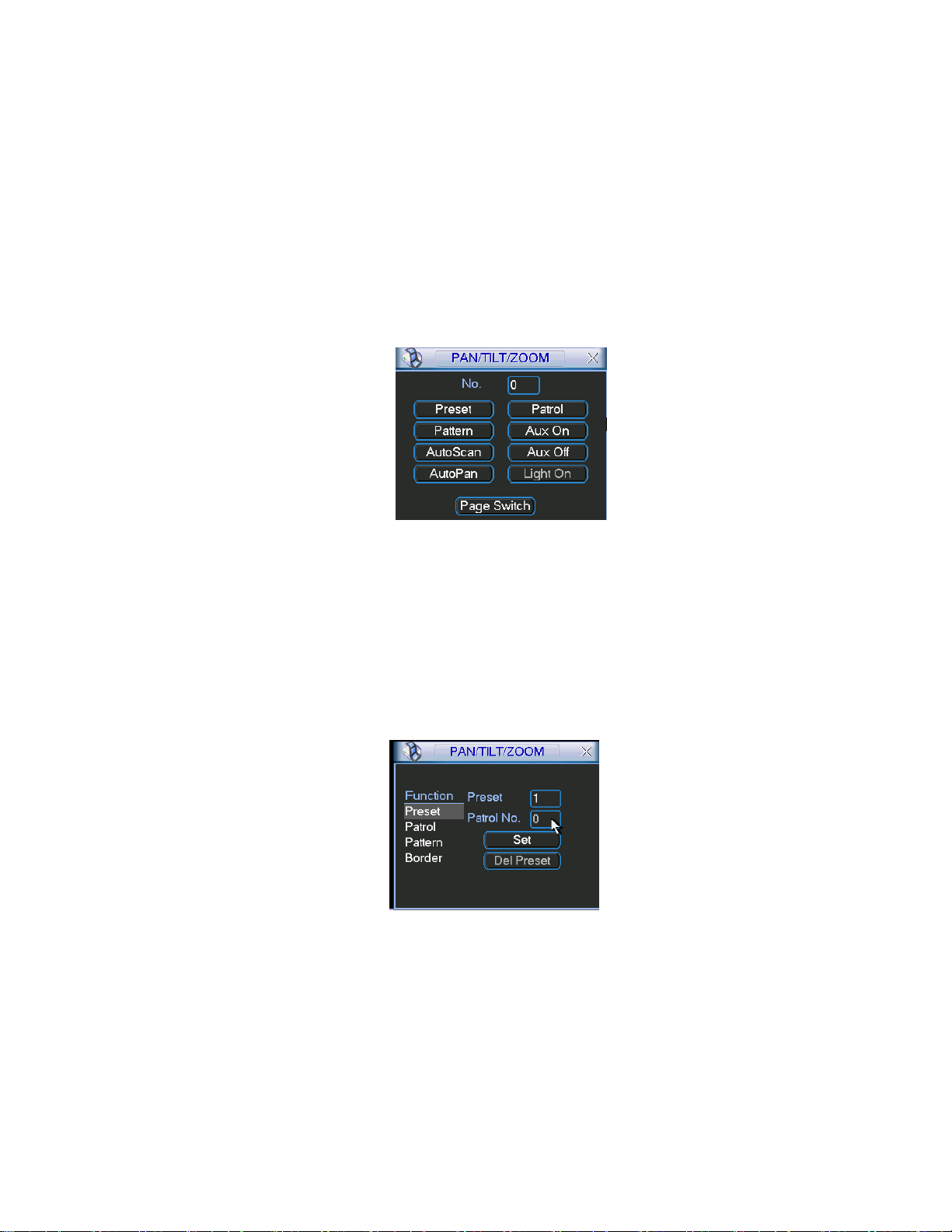
417HFigure 4-25, click page switch button, the interface is shown as in 418HFigure 4-29.
In
Here you can activate the following functions:
z Preset
z Patrol(Tour)
z Pattern
z Aux on
z Aux off
z Auto scan
z Auto pan
z Light on
Figure 4-29
Note: The following setups are usually operated in the
421HFigure 4-29 .
and
419HFigure 4-25,420HFigure 4-28
4.9.1Preset Setup
In
422HFigure 4-25, use eight direction arrows to adjust camera to the proper position.
423HFigure 4-28, click preset button and input preset number. The interface is shown
In
424HFigure 4-30.
as in
Now you can add this preset to one patrol (tour).
Figure 4-30
4.9.2 Activate Preset
In
425HFigure 4-29, please input preset number in the No. blank, and click preset button.
4.9.3 Patrol Setup (Tour setup)
In
426HFigure 4-28, click patrol button. The interface is shown as in 427HFigure 4-31.Input
preset number and add this preset to a patrol (tour). For each patrol (tour), you can
input max 80 presets.
48
Page 49
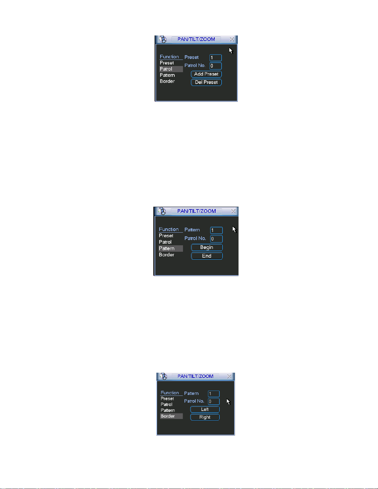
Figure 4-31
4.9.4 Activate Patrol (tour)
428HFigure 4-28, input patrol (tour) number in the No. blank and click patrol button
In
4.9.5 Pattern Set up
429HFigure 4-28, click pattern button and then click “begin” button. The interface is
In
shown as in
430HFigure 4-32. Then you can go to 431HFigure 4-25 to modify zoom, focus, and
iris.
Go back to
432HFigure 4-32 and click “end” button. You can memorize all these
operations as pattern 1.
Figure 4-32
4.9.6 Activate Pattern Function
In
433HFigure 4-29, input mode value in the No. blank, and click pattern button.
4.9.7 Auto S can S e tup
In
434HFigure 4-28, click border button. The interface is shown as in 435HFigure 4-23.
Please go to
Then please go to
436HFigure 4-25, use direction arrows to select camera left limit
437HFigure 4-33 and click left limit button
Repeat the above procedures to set right limit.
Figure 4-33
49
Page 50
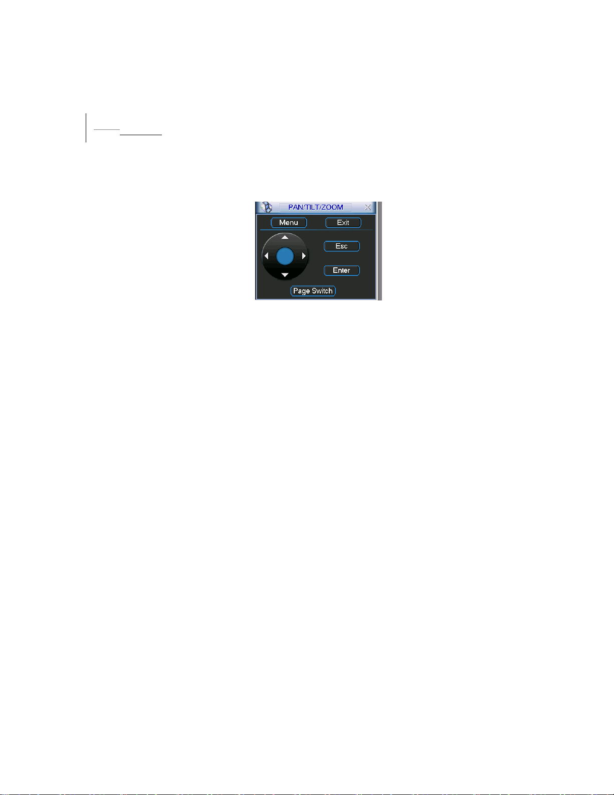
4.9.8 Activate Auto Scan
438HFigure 4-29, click “Auto Scan” button, the system begins auto scan.
In
Correspondingly, the auto scan button changes to stop button. Click stop button to
terminate scan operation.
3.104.10 Dome Menu Control
In 439HFigure 4-29, click page switch button, the interface is shown as below. See 440HFigure
4-34.
Click menu to enter dome menu. The direction arrows here are to control dome
menu. Click page switch button, system goes back to
Figure 4-34
441HFigure 4-25
50
Page 51
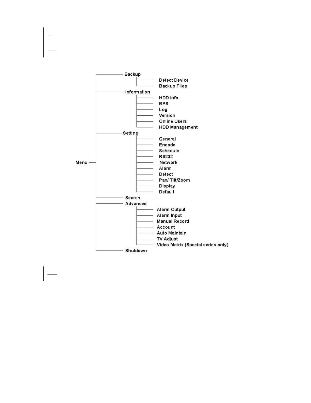
45 Understanding of Menu Operations and Controls
4.15.1 Menu Tree
This series DVR menu tree is shown as below.
4.25.2 Main Menu
When you login, the system main menu shows as below. See 442HFigure 5-1 . There are
totally six icons: search, Information, setting, backup, advanced and shutdown. Move
the cursor to highlight the icon, then double click mouse to enter the sub-menu.
51
Page 52
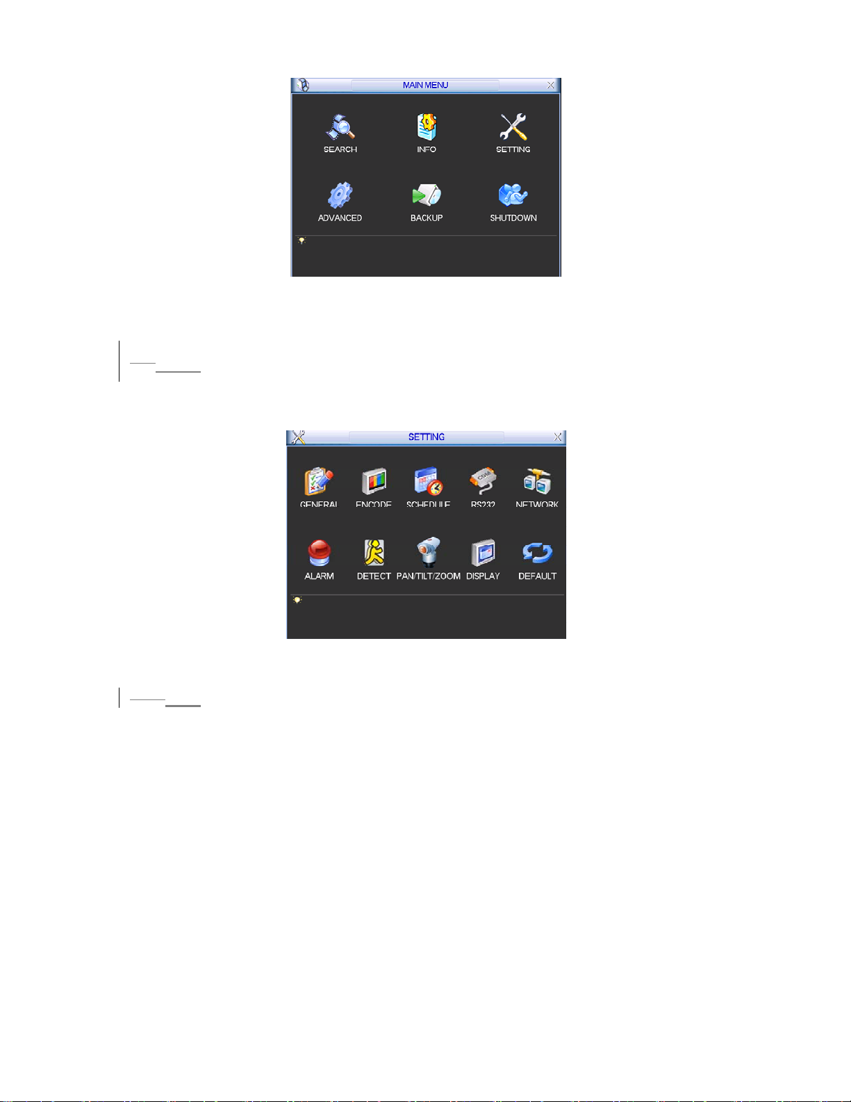
Figure 5-1
4.35.3 Setting
In main menu, highlight setting icon and double click mouse. System setting
interface is shown as below. See
443HFigure 5-2.
Figure 5-2
4.3.1
5.3.1 General
General setting includes the following items. See 444HFigure 5-3.
z System time: here is for you to set system time
z Date format: there are three types: YYYYY-MM-DD: MM-DD-YYYYY or DD-MM-
YYYY.
z Date separator: there are three denotations to separate date: dot, beeline and
solidus.
z Time format: there are two types: 24-hour mode or 12-hour mode.
z Language: system supports various languages: Chinese (simplified), Chinese
(Traditional), English, Italian, Japanese, French, Spanish (All languages listed
here are optional. Slight difference maybe found in various series.)
z HDD full: Here is for you to select working mode when hard disk is full. There are
two options: stop recording or rewrite.
z Pack duration: Here is for you to specify record duration. Default value is 60
minutes.
52
Page 53
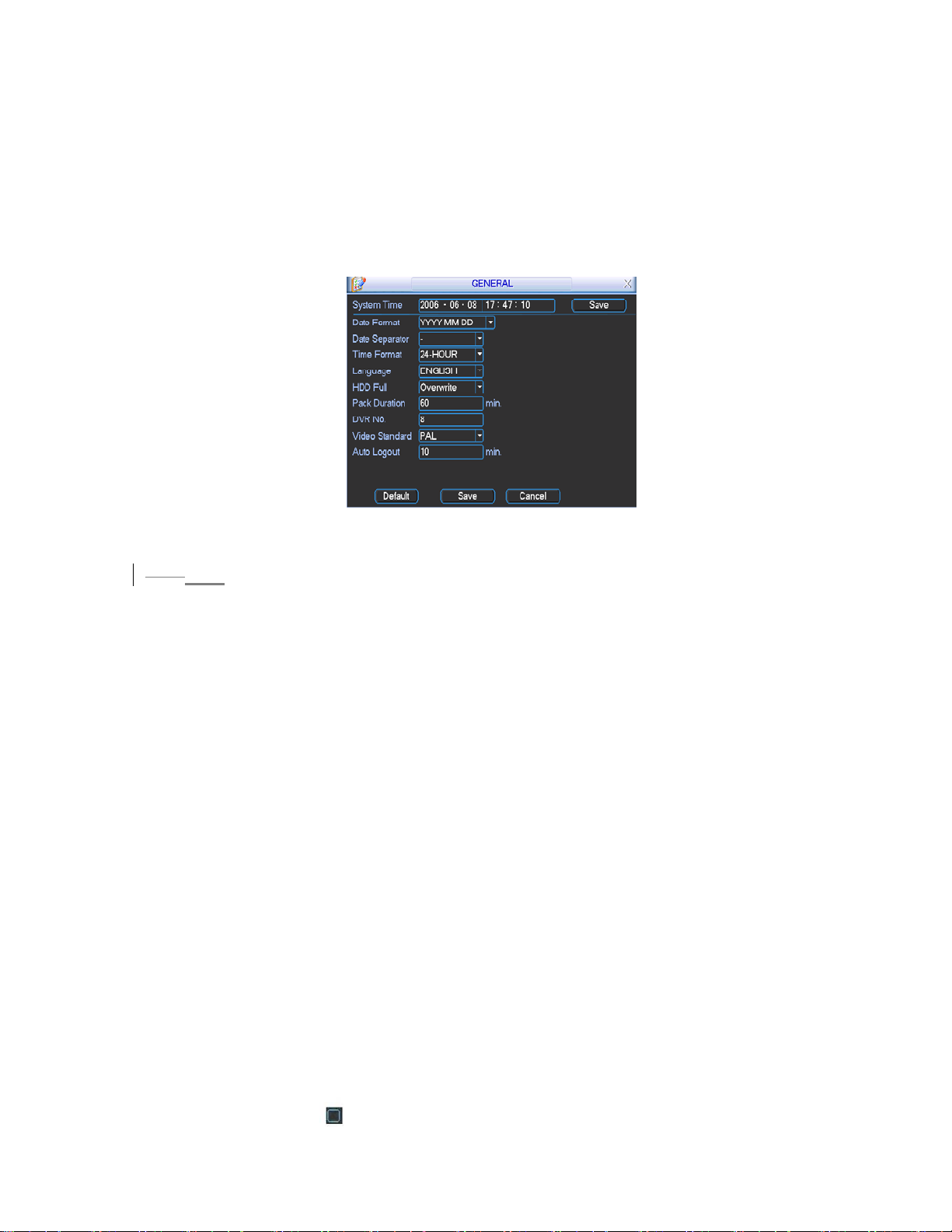
z DVR No: when you are using one remote control to control several DVRs, you
can give a name to each DVR for your management.
z Video standard: There are two formats: NTSC and PAL.
z Auto logout: Here is for you to set auto logout interval once login user remains
inactive for a specified time. Value ranges from 0 to 60 minutes.
Note: since system time is very important, do not modify time casually unless there is
a must.
After all the setups please click save button, system goes back to the previous menu.
Figure 5-3
5.3.2 Encode
4.3.2
Encode setting includes the following items. See 445HFigure 5-4.
z Channel: Select the channel you want.
z Compression: system supports H.264.Or you can select from the dropdown list.
z Resolution: System supports various resolutions, you can select from the
dropdown list. For this series, we can support CIF.
z Bit rate: system supports two types: CBR and VBR.
z Quality: There are six levels ranging from 1 to 6. Level six is the highest image
quality.
z Frame rate: there are six levels: 1 f/s,2f/s,3f/s, 6f/s,12f/s,25f/s. (Some series
DVRs only support PAL 25f/s )
z Enable audio: you can turn on or off the audio.
z Cover area (Privacy mask): Here is for you to set window blanking section. You
can drag you mouse to set proper section size.
z Time display: You can select system displays time or not.
z Channel display: You can select system displays channel number or not.
System default setup is:
z Channel:1
z Compression:H.264
z Resolution: CIF
z Bit rate: CBR
z Quality: 4
z Frame rate: 25f/s
Please highlight icon to select the corresponding function.
53
Page 54
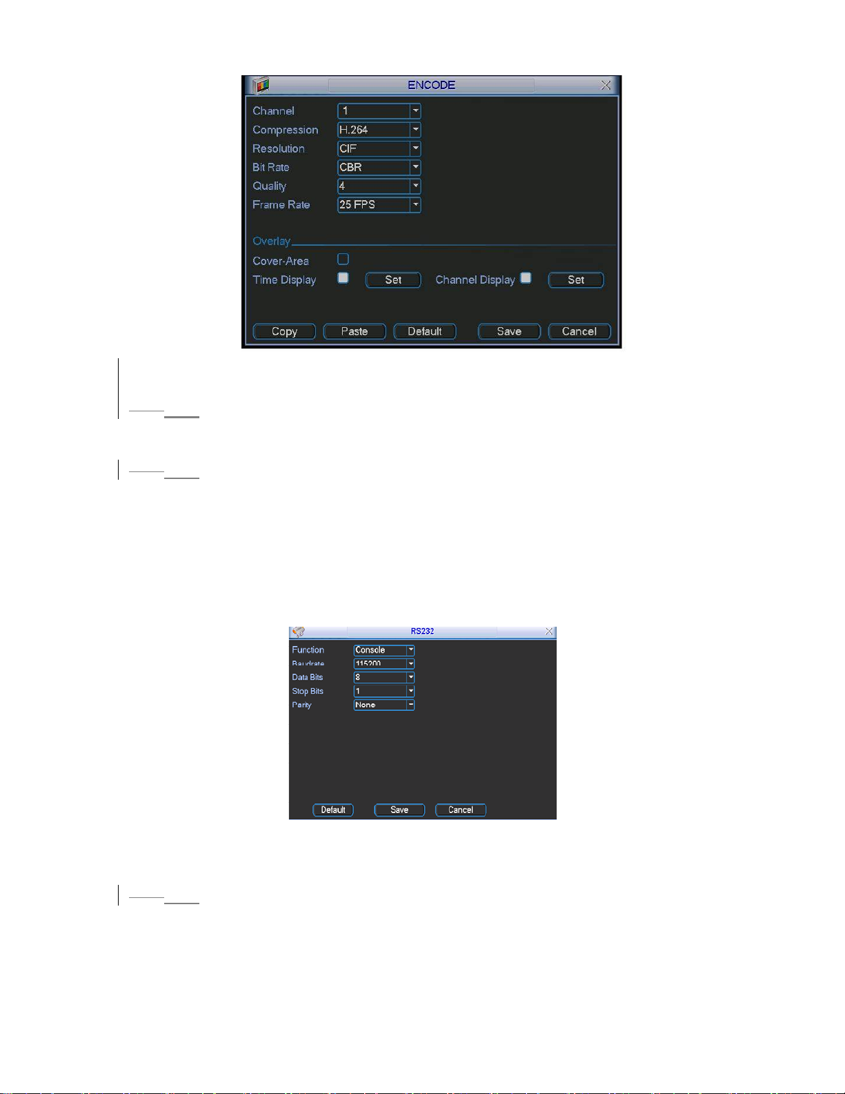
Figure 5-4
4.3.35.3.3 Schedule
Please refer to chapter 4.4 schedule.
4.3.4
5.3.4 RS232
RS232 interface is shown as below. Here are five items. See 446H Figure 5-5.
z Function: There are various devices for you to select.
z Baud rate: You can select proper baud rate.
z Data bit: You can select proper data bit.
z Stop bit: There are three values: 1/1.5/2.
z Parity: there are three choices: none/odd/even.
After all the setups please click save button, system goes back to the previous menu
Figure 5-5
5.3.5 Network
4.3.5
Here is for you to input network information. See 447HFigure 5-6.
z IP address
z Subnet mask
z Gateway
54
Page 55
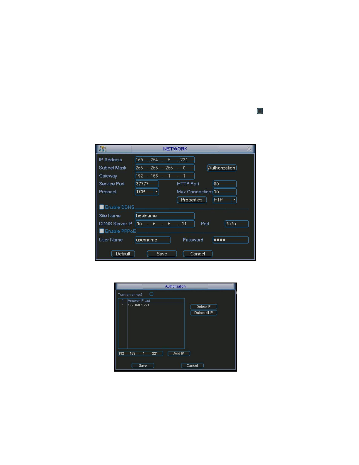
z Service port: Default value is 37777. (System server port 37778 is reserved for
network UDP use.)
z HTTP port: Default value is 80
z Protocol: You can select proper protocol from the dropdown list.
z Max connection: support maximal 10 users.
z Properties: There are three options for you: FTP/NTP/Alarm center. You can
select corresponding ways and then click properties button to go to setup
interface.
z Authorization: Click authorization button please highlight icon to enable IP
authentication function. When you enable this function, only IP in the list can login
this DVR. See
448HFigure 5-7.
After all the setups please click save button, system goes back to the previous menu.
Figure 5-6
Figure 5-7
55
Page 56
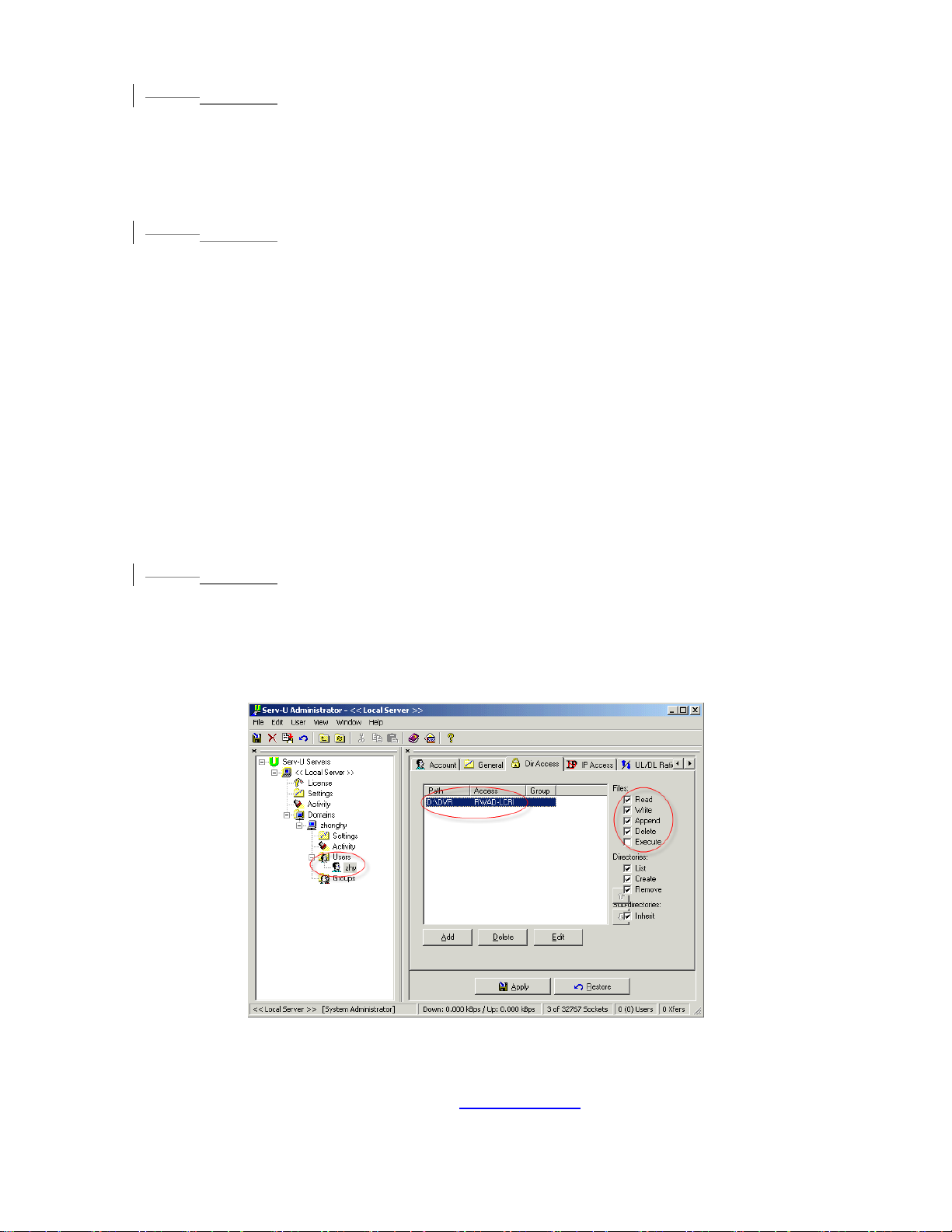
4.3.5.1
5.3.5.1 PPPoE Connection
Enable PPPoE function and then input “PPPoE name” and “PPPoE password” you
get from your ISP (Internet service provider).
Click save button, you need to restart to activate your configuration.
After rebooting, IP camera will connect to internet automatically. The IP in the
PPPoE is the dynamic value.
4.3.5.2
5.3.5.2 Web visit via PPPoE
There are two ways.
a. visit via current IP
After DVR connected with Internet by PPPoE, please get your device’s current IP
449HFigure 5-6. Now you can visit this IP camera via this IP.
in
b. Visit via DNS
You need a PC of fixed IP in the internet and there is the DDNS software running in
this PC. In other words, this PC is a DNS (domain name server).
In network DDNS, input your PPPoE name you get from you IPS and server IP (PC
with DDNS ) . Click save button and then reboot system.
Click save button, system prompts for rebooting to get all setup activated.
After rebooting, open IE and input as below:
http://(DDNS server IP)/(virtual directory name)/webtest.htm
e.g.: http://10.6.2.85/DVR _DDNS/webtest.htm.)
Now you can open DDNSServer web search page.
4.3.5.3
5.3.5.3 FTP
You need to download or buy FTP service tool (such as Ser-U FTP SERVER) to
establish FTP service.
Please install Ser-U FTP SERVER first. From “start” -> “program” -> Serv-U FTP
Server -> Serv-U Administator. Now you can set user password and FTP folder.
Please note you need to grant write right to FTP upload user. See
450HFigure 5-8.
Figure 5-8
You can use a PC or FTP login tool to test setup is right or not.
For example, you can login user ZHY to
or delete folder or not. See
451HFigure 5-9.
180HFTP://10.10.7.7 and then test it can modify
56
Page 57
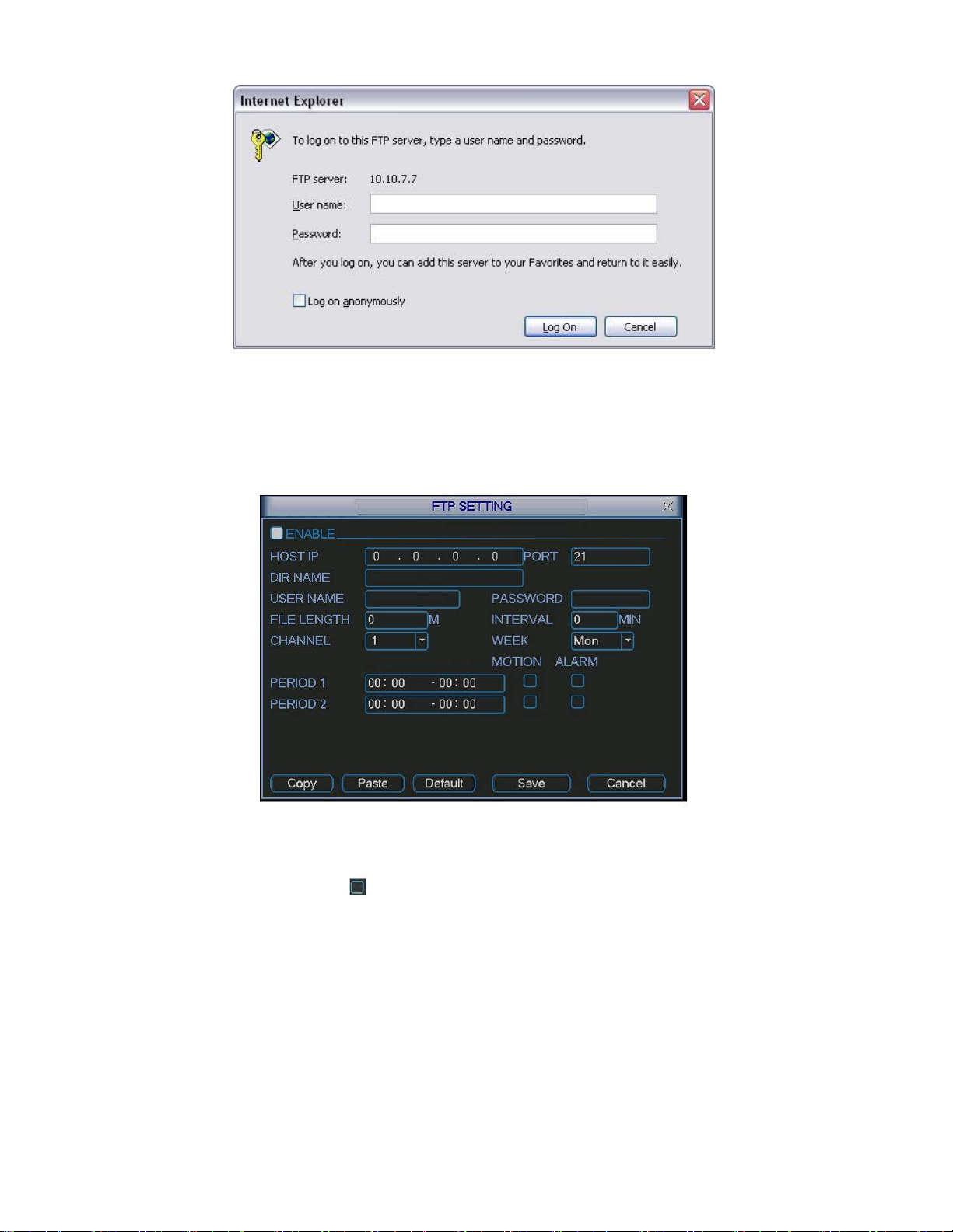
Figure 5-9
System also supports upload multiple DVRs to one FTP server. You can create
multiple folders under this FTP.
452HFigure 5-6, select FTP and then click properties button. You can see the following
In
interface. See
453HFigure 5-10.
Figure 5-10
Please highlight the icon in front of Enable to activate FTP function.
Now FTP can upload alarm video and motion detection video. Please note, when
you are using this function, please make sure current upload channel is in motion
detection or alarm record status and there is video available.
Here you can input FTP server address, port and etc.
57
Page 58
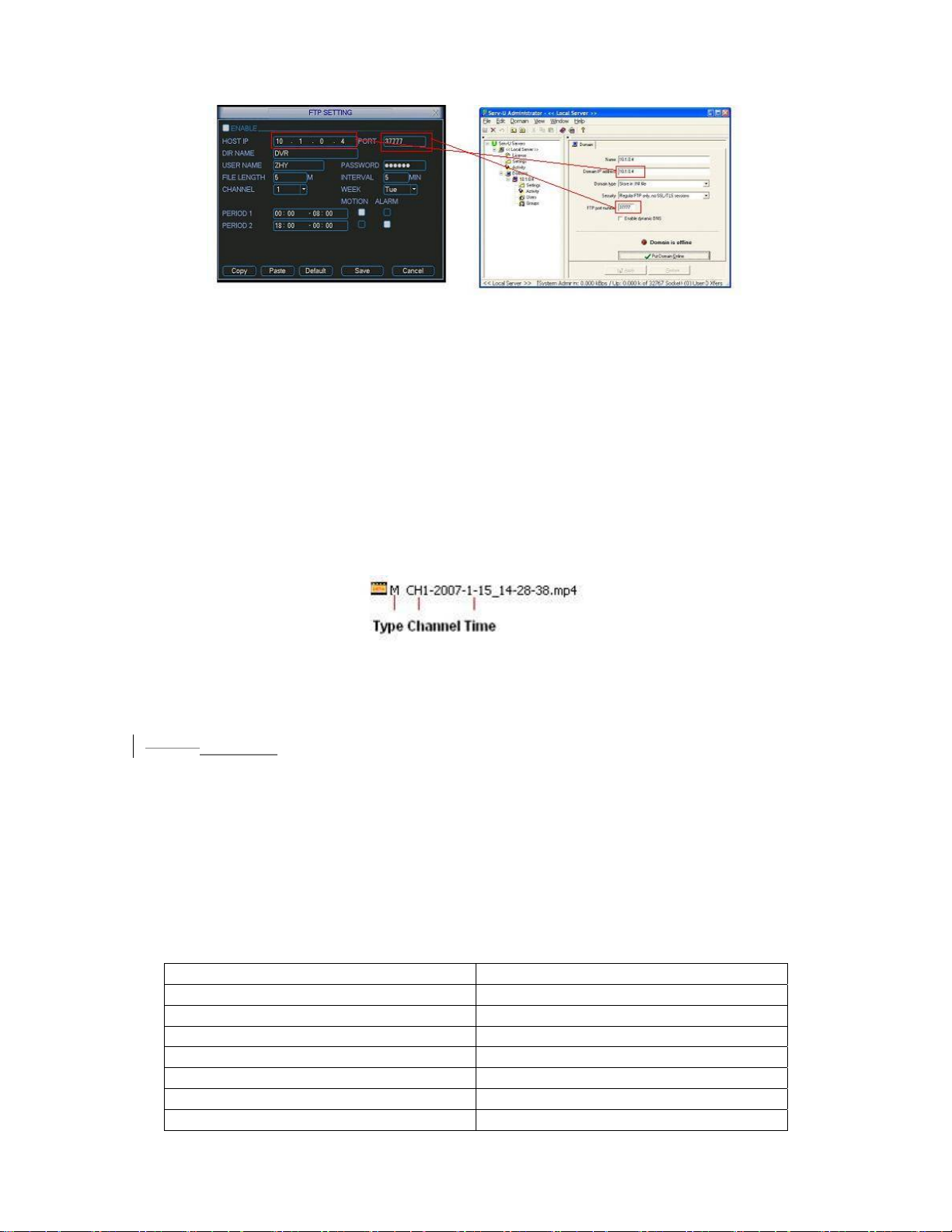
Figure 5-11
z File length: upload file length. When setup is larger than the actual file length,
system will upload the whole file. When setup here is smaller than the actual file
length, system only uploads the set length and auto ignore the left section.
z Interval: in each channel, system only uploads the first video file in accordance
with video type (alarm/motion detection) during the same period. For example,
when interval value is 5 minutes, system only uploads the first motion detection
or alarm file in each 5-minute.
z When interval value is 0, system uploads all corresponding files.
z Period 1 and period 2: you can set two periods for one each channel.
System file name is shown as in
454H Figure 5-12.
Figure 5-12
4.3.5.4
5.3.5.4 NTP
You need to install SNTP server (Such as Absolute Time Server) in your PC first. In
Windows XP OS, you can use command “net start w32time” to boot up NTP service.
455HFigure 5-6, select NTP and then click properties button. You can see the following
In
interface. See
456HFigure 5-13.
z Host IP: Input your PC address.
z Port: This series DVR supports TCP transmission only. Port default value is 123.
z Update interval: minimum value is 15(Unit: minute)
z Time zone: select your corresponding time zone here.
Here is a sheet for your time zone setup.
City /Region Name Time Zone
London GMT+0
Berlin GMT+1
Cairo GMT+2
Moscow GMT+3
New Deli GMT+5
Bangkok GMT+7
Beijing (Hong Kong) GMT+8
58
Page 59
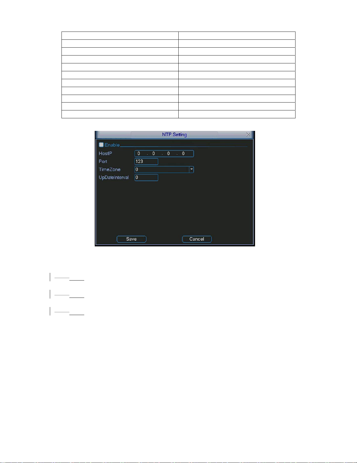
Tokyo GMT+9
Sydney GMT+10
Hawaii GMT-10
Alaska GMT-9
Pacific Time(P.T) GMT-8
American Mountain Time(M.T) GMT-7
American Central Time(C.T) GMT-6
American Eastern Time(E.T) GMT-5
Atlantic Time GMT-4
Brazil GMT-3
Middle Atlantic Time GMT-2
Figure 5-13
4.3.6
5.3.6 Alarm
Please refer to chapter 4.6 Alarm Setup and Activation.
4.3.7
5.3.7 Detect
Please refer to chapter 4.5 Detect.
5.3.8 Pan/Tilt/Zoom
4.3.8
The pan/tilt/zoom setup includes the following items. Please select channel first.
457HFigure 5-14.
See
z Protocol: select corresponding PTZ protocol such as DH-SD1.
z Address: input corresponding PTZ address.
z Baud rate: select baud rate.
z Data bit: select data bit.
z Stop bit: select stop bit.
z Parity: there are three choices: none/odd/even.
After all the setups please click save button, system goes back to the previous menu.
For detailed setup, please refer to chapter 4.9 preset/patrol/pattern/scan.
59
Page 60
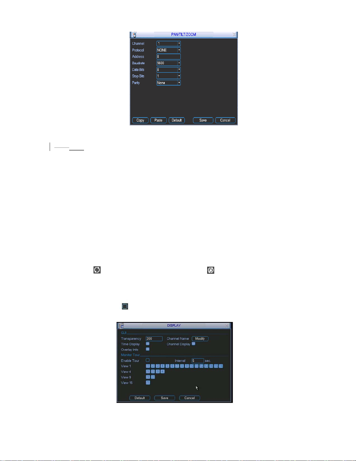
Figure 5-14
5.3.9 Display
4.3.9
Display setup interface is shown as below. See 458HFigure 5-15.
z Transparency: Here is for you to adjust transparency. The value ranges from 128
to 255.
z Channel name: Here is for you to modify channel name. Please note all your
modification here only applies to DVR local end. You need to open web or client
end to refresh channel name.
z Time display: You can select display time or not.
z Channel display: You can select channel name or not.
z Overlay information: System displays some information in the screen for your
reference.
z Enable tour: activate tour function.
z Interval: Input proper interval value here. The value ranges from 5-200 seconds.
In tour process, you can use mouse or click Shift to turn on window switch
function. Stands for opening switch function, stands for closing switch
function.
z View1/4/9/16: System support 1/4/9/16 window tour.
Please highlight icon to select the corresponding function.
After all the setups please click save button, system goes back to the previous menu.
Figure 5-15
60
Page 61
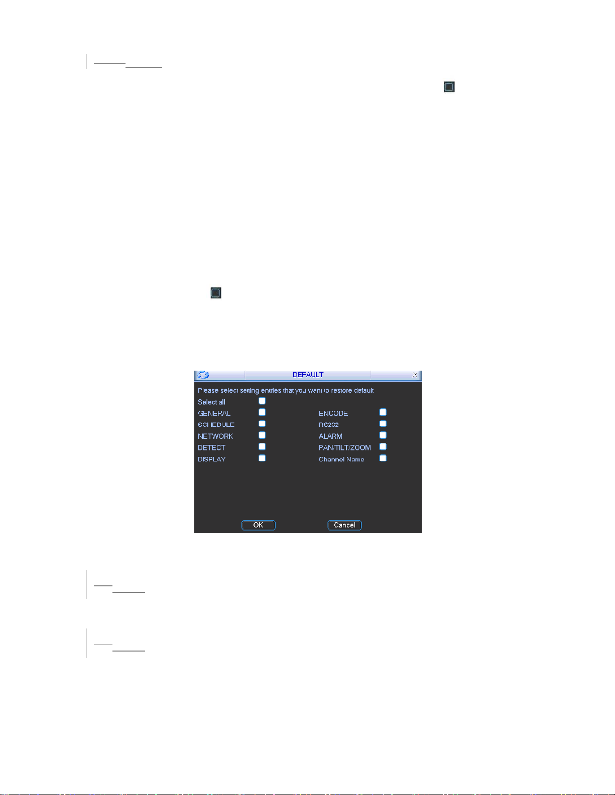
4.3.10
5.3.10 Default
Click default icon, system pops up a dialogue box. You can highlight to restore
default factory setup. See
459HFigure 5-16.
z Select all
z General
z Encode
z Schedule
z RS232
z Network
z Alarm
z Detect
z Pan/tilt/zoom
z Display
z Channel name
Please highlight icon to select the corresponding function.
After all the setups please click save button, system goes back to the previous menu.
Warning!
System menu color, language, time display mode, video format, IP address, user
account will not maintain previous setup after default operation!
Figure 5-16
4.45.4 Search
Please refer to chapter 4.3 Search.
4.55.5 Advanced
Double click advanced icon in the main window, the interface is shown as below.
See
460HFigure 5-17. There are totally seven function keys: hard disk management,
alarm output, alarm input, manual record, account, auto maintain, and TV adjust.
61
Page 62
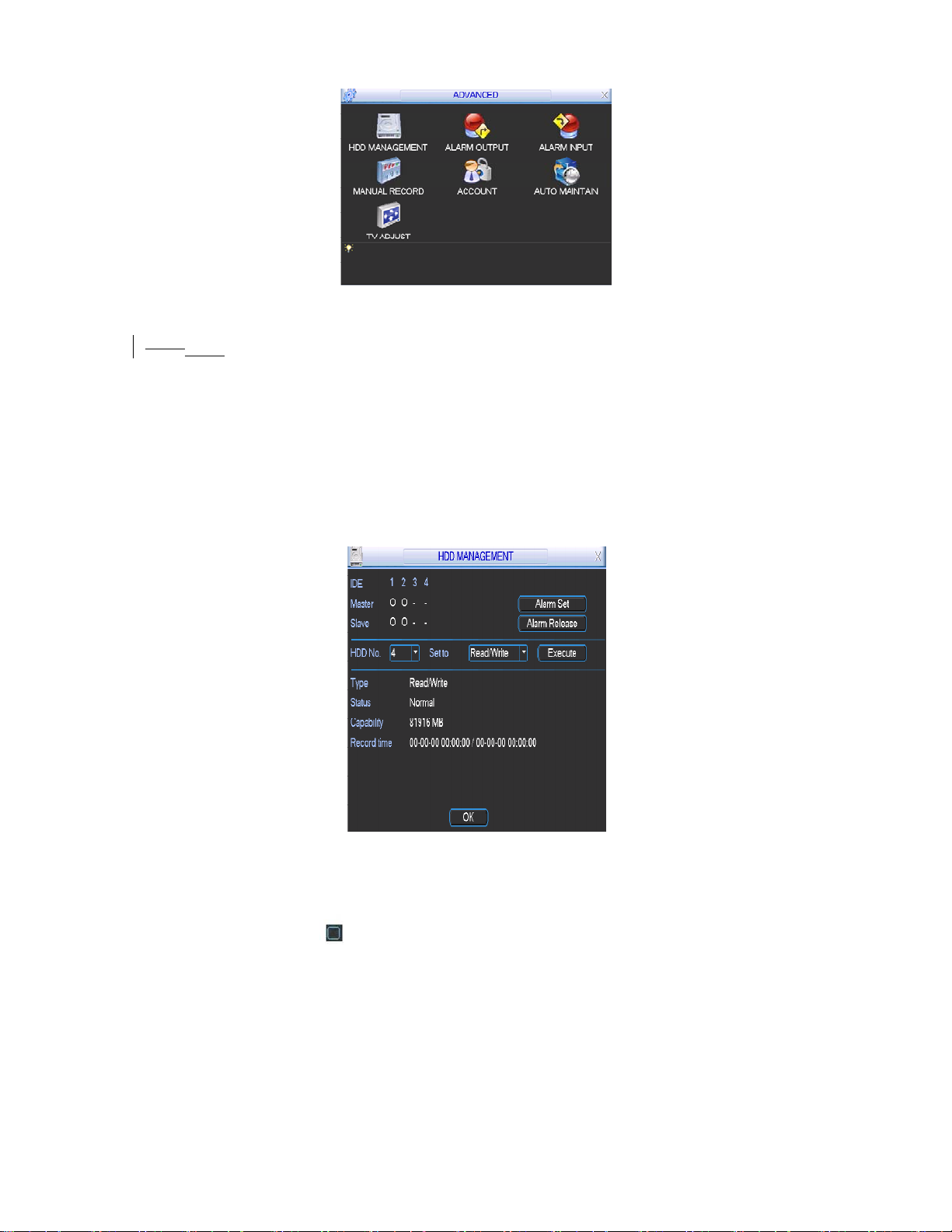
Figure 5-17
5.5.1 Hard Disk Management
4.5.1
Here is for you to view and implement hard disk management. See 461HFigure 5-18.
You can set proper mode for each hard disk from the dropdown list.
When you use redundant backup function, you can set one or more redundant
HDD(s).
Please note you need to set at least one read-write disk, otherwise system will not
record video. For detailed information you can refer to chapter 4.4 Schedule.
After all the setups please click save button, system needs to reboot to get all the
modification activated.
Figure 5-18
Click alarm set button, the interface is shown as below. See
462HFigure 5-19.
Please highlight icon to select the corresponding function.
You can enable one or more alarm setups. The lower limit ranges from 1% to 99%.
Alarm channel number ranges from 1 to 6. Delay value is from 0 to 240 seconds.
Please note when HDD capacity is not full system only alarms once!
After all the setups please click OK button, system goes back to the previous menu
62
Page 63
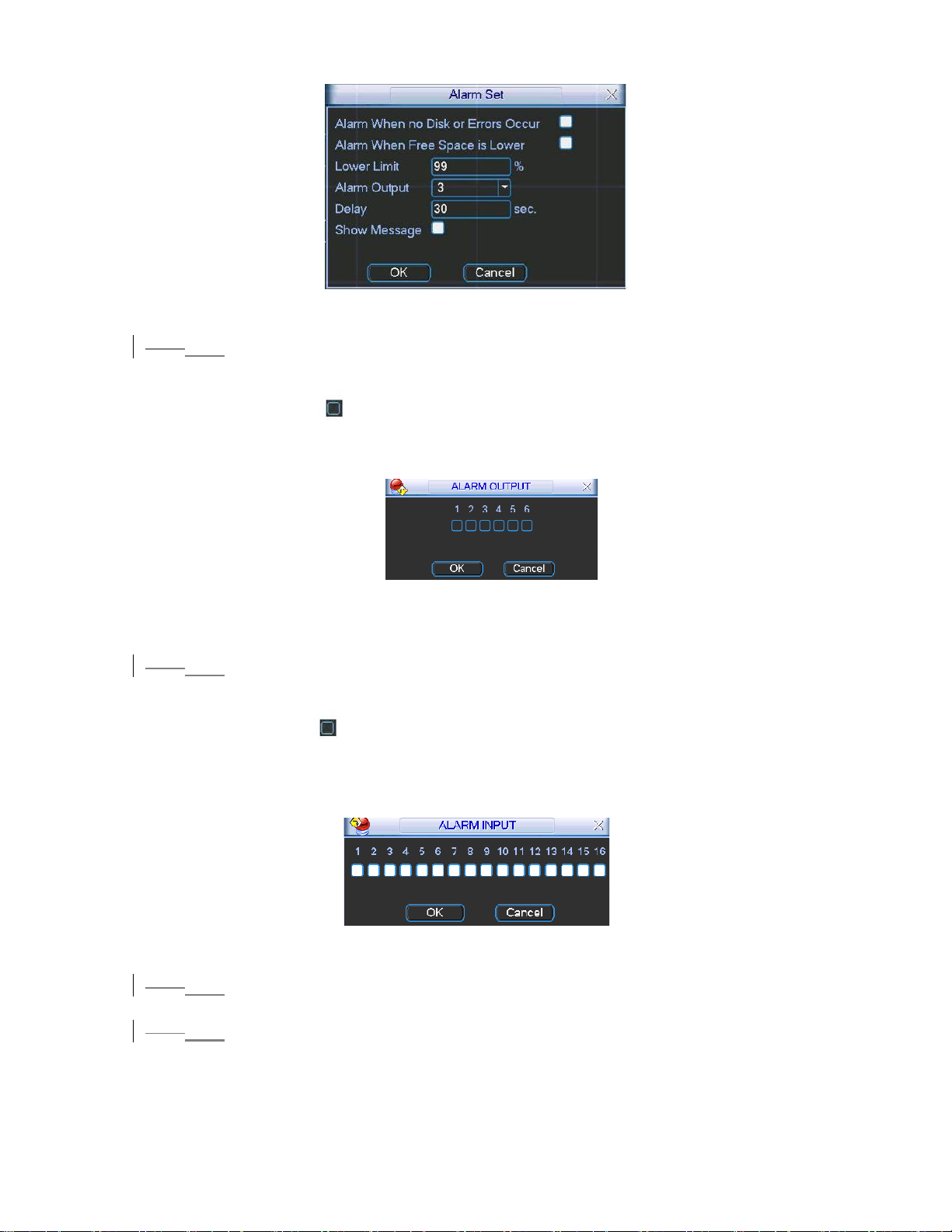
Figure 5-19
5.5.2 Alarm Output
4.5.2
Here is for you to set proper alarm output.
Please highlight icon to select the corresponding alarm output.
After all the setups please click OK button, system goes back to the previous menu.
See
463HFigure 5-20.
Figure 5-20
4.5.3
5.5.3 Alarm Input
Here is for you to set alarm input.
Please highlight icon to select the corresponding input channel.
After all the setups please click save button, system goes back to the previous menu.
464HFigure 5-21.
See
Figure 5-21
4.5.4
5.5.4 Manual Record
Please refer to chapter 4.2.2 manual record.
5.5.5 Account
4.5.5
Here is for you to implement account management. See 465HFigure 5-22. Here you can:
z Add new user
z Modify user
z Add group
63
Page 64
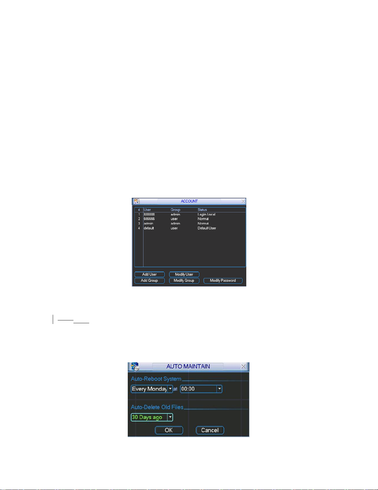
z Modify group
z Modify password.
For account management please note:
z System account adopts two-level management: group and user. No limit to group
or user amount.
z For group or user management, there are two levels: admin and user.
z The user name and group name can consist of eight bytes. One name can only
be used once. There are four default users: admin/888888/666666 and hidden
user “default”. Except user 6666, other users have administrator right.
z Hidden user “default” is for system interior use only and can not be deleted.
When there is no login user, hidden user “default” automatically login. You can
set some rights such as monitor for this user so that you can view some channel
view without login.
z One user should belong to one group. User right can not exceed group right.
z About reusable function: this function allows multiple users use the same
account to login.
After all the setups please click save button, system goes back to the previous menu.
Figure 5-22
5.5.6 Auto Maintain
4.5.6
Here you can set auto-reboot time and auto-delete old files setup. See 466HFigure 5-23.
You can select proper setup from dropdown list.
After all the setups please click save button, system goes back to the previous menu.
Figure 5-23
64
Page 65
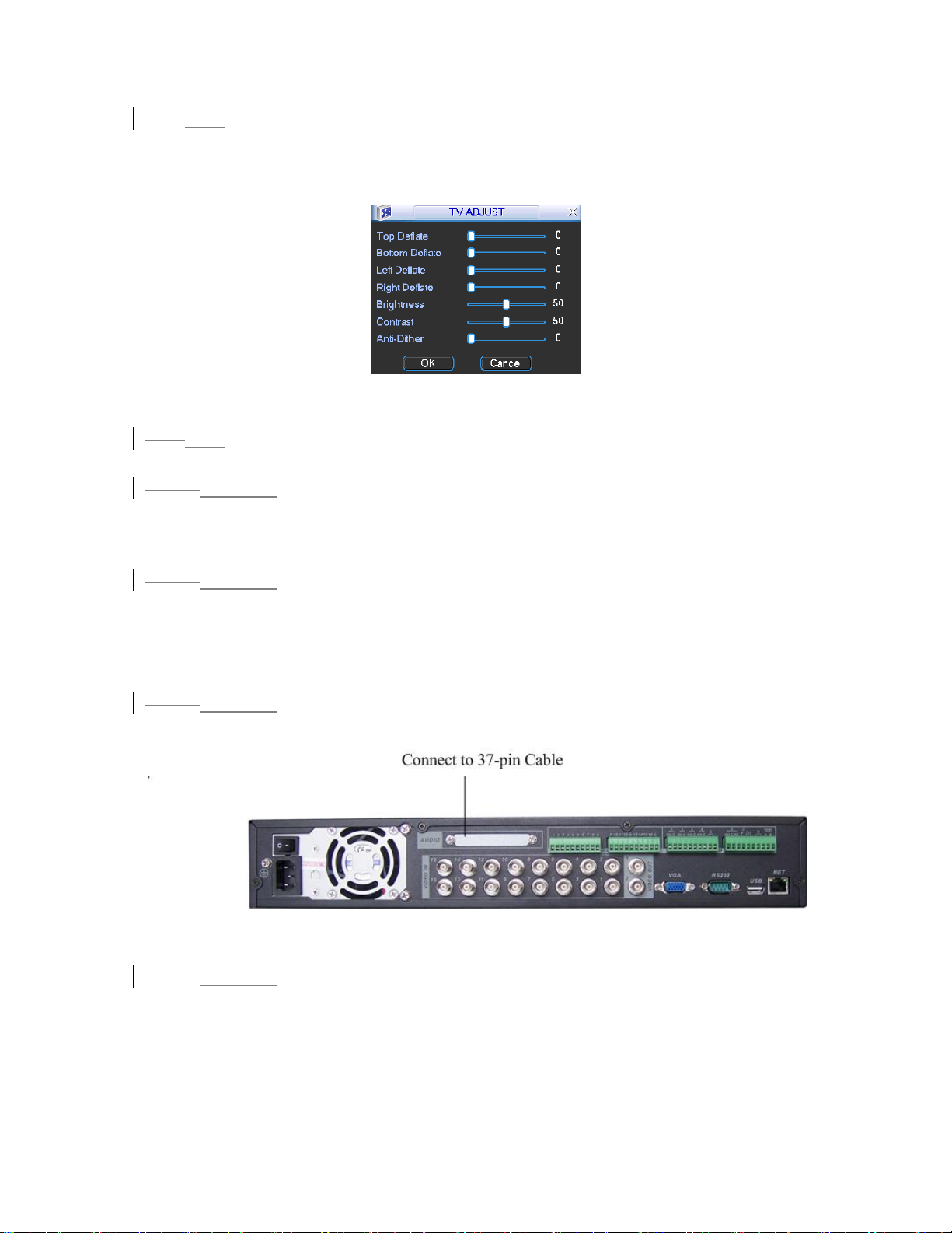
5.5.7 TV Adjust
4.5.7
Here is for you to adjust TV output setup. See 467HFigure 5-24.
Please drag slide bar to adjust each item.
After all the setups please click OK button, system goes back to the previous menu.
Figure 5-24
4.5.8
5.5.8 Video Matrix (For DVR 1604LNH-S Series Only)
Some series DVR have the matrix and loop outputs.
4.5.8.1
5.5.8.1 Loop outputs
They are just the same with video distributors. There are 16-ch video loop outputs
from our DVR. The DVR video output can connect with other devices such as TV
walls, analog matrix and so on.
4.5.8.2
5.5.8.2 Matrix outputs
They are like the small-scale matrix. You can select any camera from our DVR to
switch. And the output can also tour between the cameras. So the matrix outputs can
be used to build TV walls and tour and display the cameras one by one.
4.5.8.3
5.5.8.3 Rear Panel Connection
The rear panel is shown as below. See 468HFigure 5-25.
Figure 5-25
4.5.8.45.5.8.4 37-pin cable introduction
There are three colors cable. See 469HFigure 5-26.
z Black: for loop outputs, there are 16-ch loop outputs
z Blue: for matrix outputs, there are 4-ch matrix outputs
z White: for bi-direction talk, one is for audio in and the other is for audio out.
65
Page 66
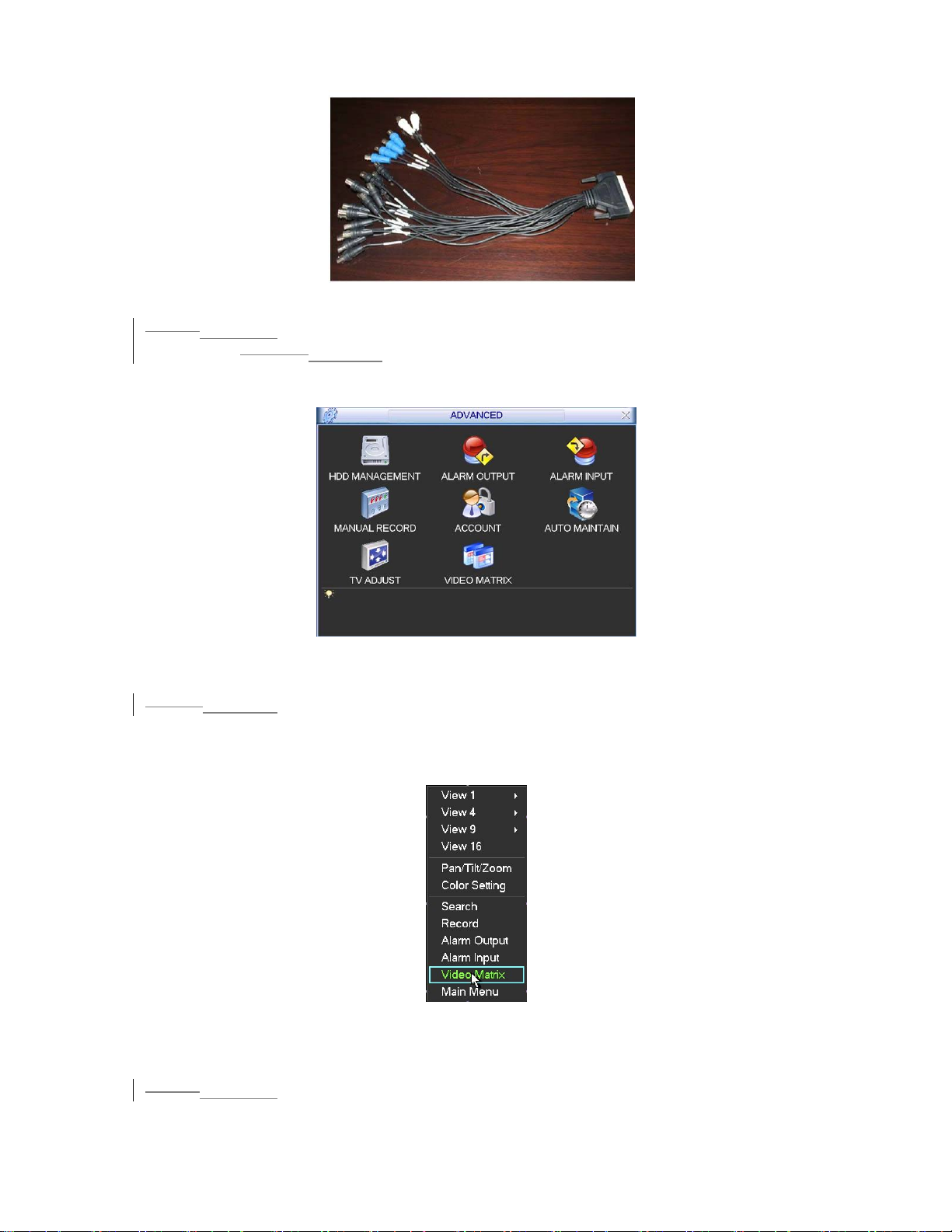
Figure 5-26
4.5.8.5
5.5.8.5 Matrix setup
4.5.8.5.15.5.8.5.1 Enter the Menu of Video Matrix
In the menu, from “Advanced” to “Video Matrix”. See 470HFigure 5-27.
Figure 5-27
4.5.8.5.25.5.8.5.2 Right mouse menu
In one-window display mode, right click mouse to select “Video Matrix”. See 471HFigure
5-28.
Figure 5-28
4.5.8.65.5.8.6 Video Matrix Interface and Application
LNH-S series support 1-channel matrix outputs. The video matrix interface is shown
472HFigure 5-29.
as in
66
Page 67
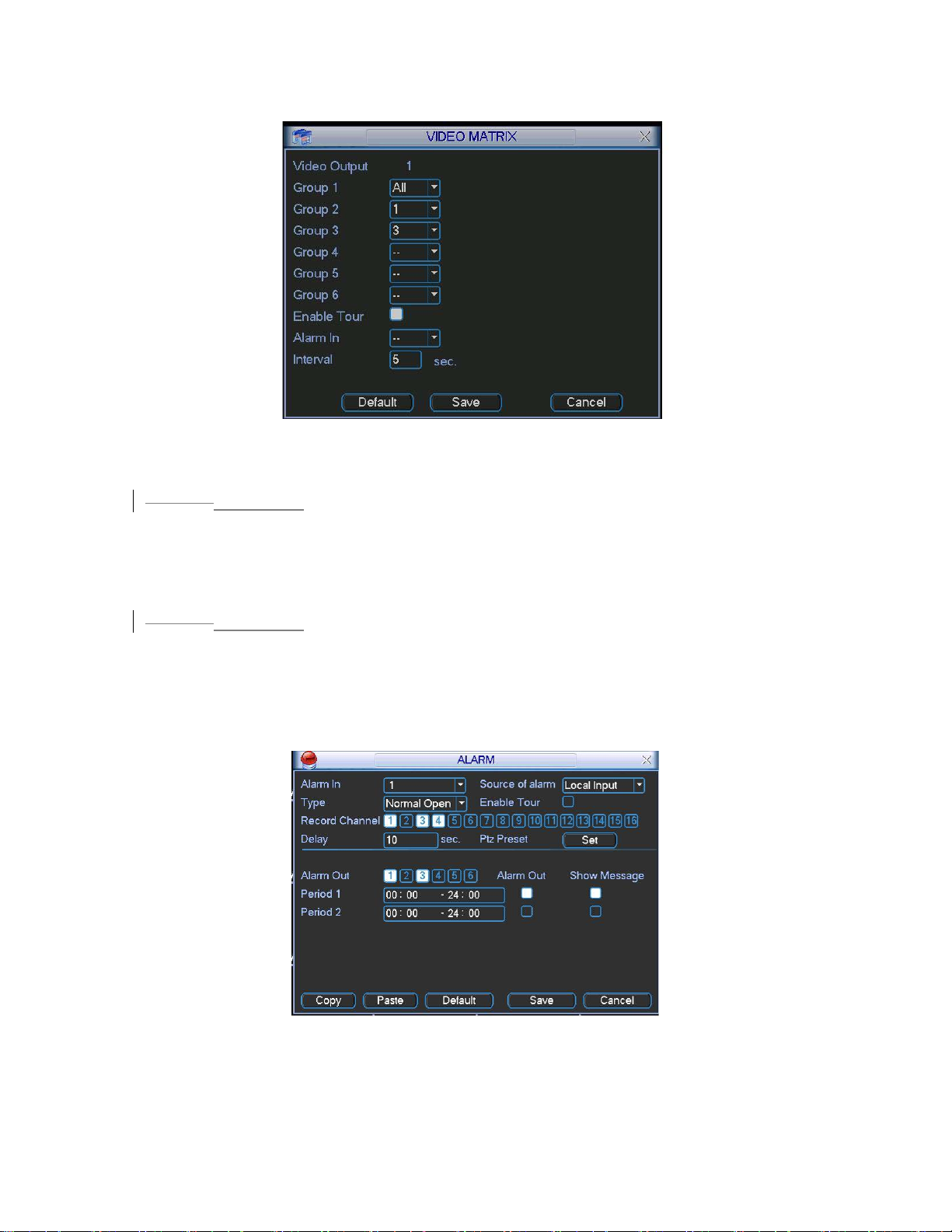
You can set for each channel. The function consists of two types
.
Figure 5-29
4.5.8.6.15.5.8.6.1 Single Tour
Please enable tour function. Then set interval time and select corresponding cameras.
You can select “ALL” to tour between all channels.
Note:
z ”- -“means that there is no alarm activation tour.
4.5.8.6.2
5.5.8.6.2 Alarm Tour
Select the “alarm in” channel number from the dropdown list. If there is an alarm
signal from the channel selected, the matrix output will go to tour as you set in the
“Alarm” setting (Main Menu->Setting->Alarm). See
473HFigure 5-30.
Alarm tour has higher priority than single tour during this period, the single tour will
stop. After alarm activation tour, the matrix output will continue single tour.
Figure 5-30
67
Page 68
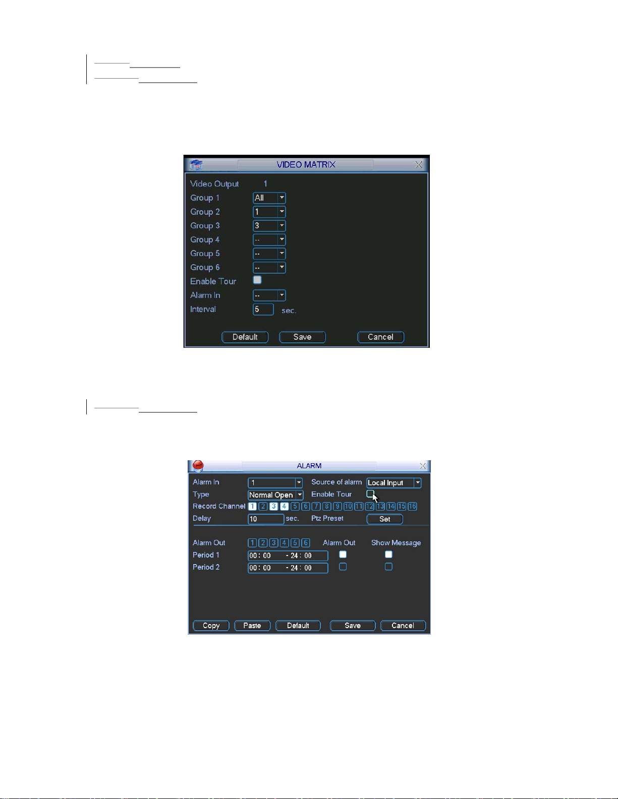
4.5.8.7
5.5.8.7 Examples
4.5.8.7.15.5.8.7.1 Example one
In 474HFigure 5-31, matrix outputs”1”, “3”, “4” tour between all cameras of the DVR.
Matrix output 2 tours between “CAM1, CAM6 and CAM7” of the DVR. The interval is
five seconds.
Figure 5-31
4.5.8.7.25.5.8.7.2 Example two
In 475HFigure 5-32, when alarm occurs in channel one, the activated matrix output one
begins touring between CAM1, CAM3 and CAM4 of the DVR until alarm activation
tour stops.
Figure 5-32
68
Page 69
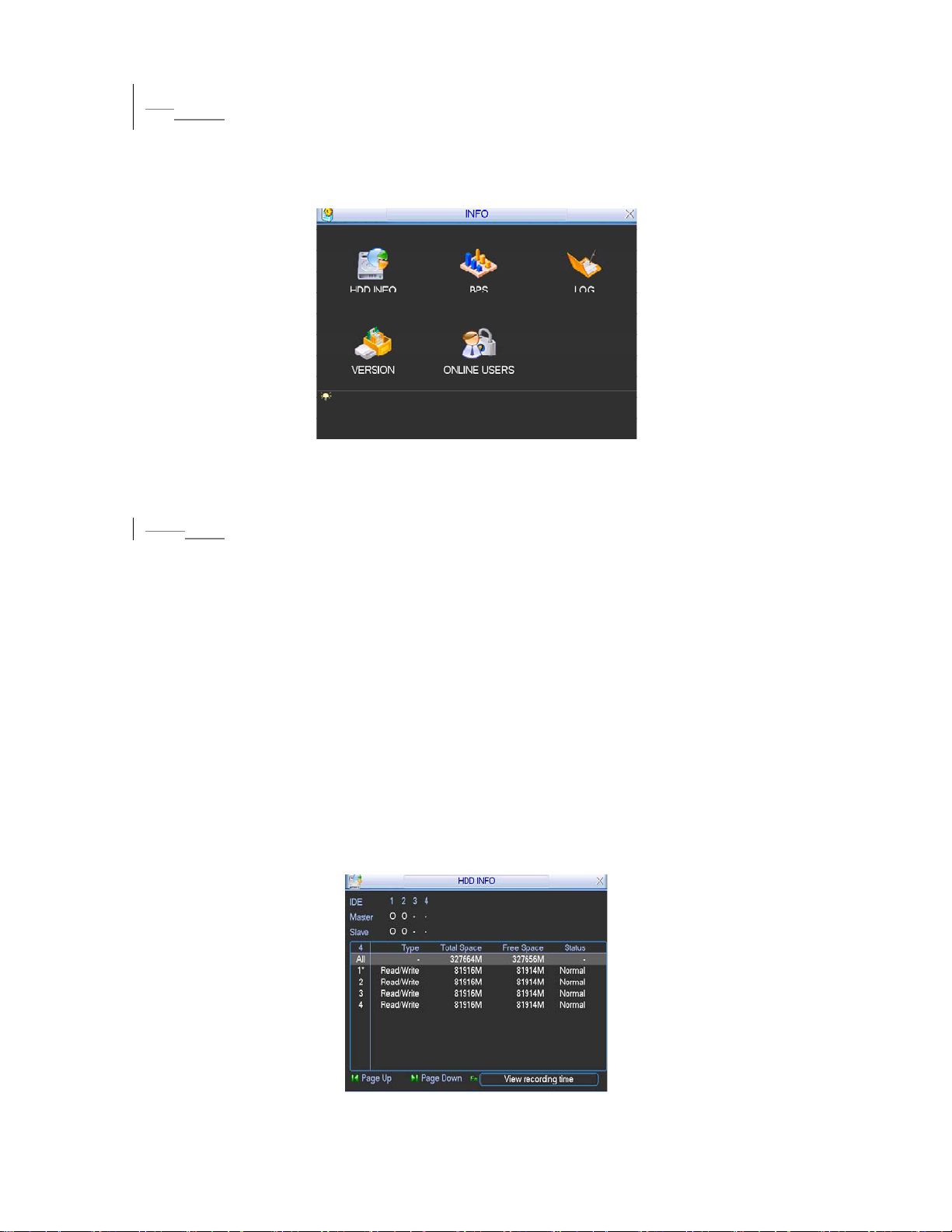
4.65.6 Information
Here is for you to view system information. There are totally five items: HDD (hard
disk information), BPS (data stream statistics), Log and version, and online user.
476HFigure 5-33.
See
Figure 5-33
4.6.1
5.6.1 Hard Disk Information
Here is to list hard disk type, total space, free space, video start time and status.
See
477HFigure 5-34.
Note:
Please remove the broken hard disk before you add a new one.
Once there is a hard disk confliction, please check hard disk time and system time is
the same or not. Please go to setting then general to modify system time. At last,
reboot the system to solve this problem.
In IDE information column, ○means OK,X means error occurred 、- means there
is no disk.
The serial number after the disk information such as ○,which means it is current
working disk.
If disk is damaged, system shows as “?”
Figure 5-34
69
Page 70
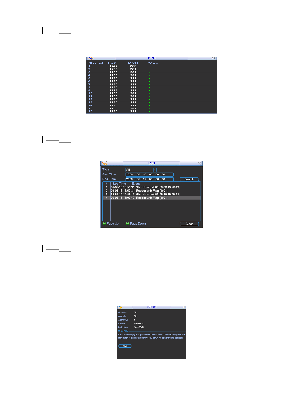
5.6.2 BPS
4.6.2
Here is for you to view current video data stream (KB/s) and occupied hard disk
storage (MB/h). See
478HFigure 5-35.
Figure 5-35
4.6.3
5.6.3 Log
Here is for you to view system log file. System lists the following information.
479HFigure 5-36.
See
Figure 5-36
4.6.4
5.6.4 Version
Here is for you to view some version information. See 480HFigure 5-37.
z Channel
z Alarm in
z Alarm out
z System version:
z Baud rate:
z Start upgrade
70
Page 71
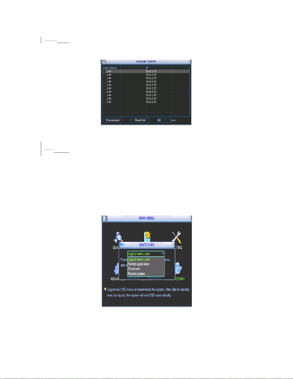
Figure 5-37
5.6.5 Online Users
4.6.5
Here is for you manage online users. See 481HFigure 5-38.
You can disconnect one user or block one user if you have proper system right.
Figure 5-38
4.75.7 Exit
Double click exit button, system pop up a dialogue box for you to select. See 482HFigure
5-39.
z Logout menu user: log out menu. You need to input password when you login
the next time.
z Restart application: reboot DVR.
z Shutdown: system shuts down and turns off power.
z Restart system: system begins rebooting.
Figure 5-39
71
Page 72
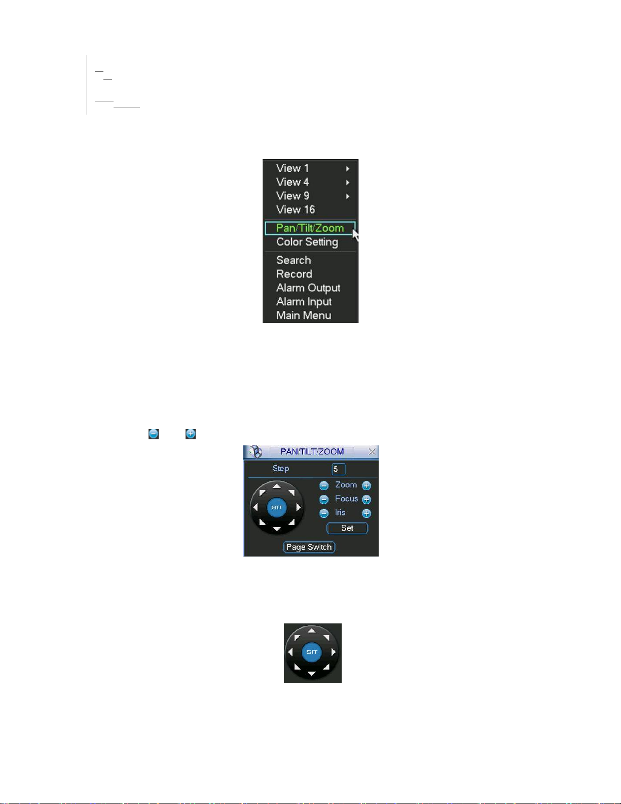
56 About Auxiliary Menu
5.16.1 Go to Pan/Tilt/Zoom Menu
In the one-window surveillance mode, right click mouse (click “fn” Button in the front
panel or click AUX key in the remote control). The interface is shown as below:
See
483HFigure 6-1.
Figure 6-1
Click Pan/Tilt/Zoom, the interface is shown as in
Here you can set the following items:
z Zoom
z Focus
z Iris
Click icon and to adjust zoom, focus and Iris.
484HFigure 6-2.
Figure 6-2
In
485HFigure 6-2, please click direction arrows (See 486HFigure 6-3 ) to adjust PTZ position.
There are totally eight direction arrows. (Please note there are only four direction
arrows in DVR front panel.)
Figure 6-3
72
Page 73
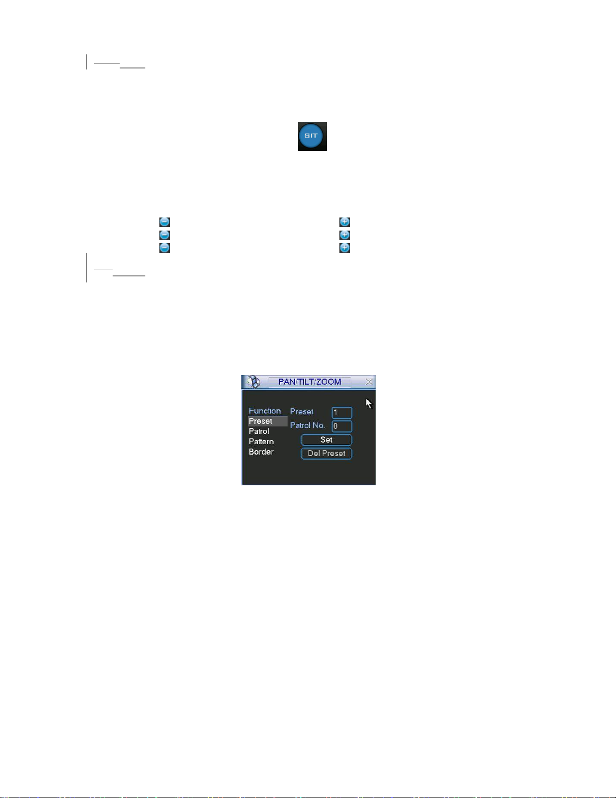
5.1.16.1.1 3D Intelligent Positioning Key
In the middle of the eight direction arrows, there is a 3D intelligent positioning key.
487HFigure 6-4 . Click this button, system goes back to the single screen mode.
See
Drag the mouse in the screen to adjust section size.
Figure 6-4
Here is a sheet for you reference.
Name Function
key
Zoom
Focus
Iris
function Shortcut
key
Near Far
Near
close
_
W
Function
key
function Shortcut
key
Far
Open
f
5.26.2 Preset /Patrol / Pattern /Border Function
In 488HFigure 6-2 click the set button. The interface is shown as below:
Here you can set the following items:
z Preset
z Patrol
z Pattern
z Border
Figure 6-5
In
489HFigure 6-2, click page switch button, you can see an interface as in 490HFigure 6-6.
Here you can activate the following functions:
z Preset
z Patrol
z Pattern
z Aux on
z Aux off
z Auto scan
z Auto pan
z Light on
73
Page 74
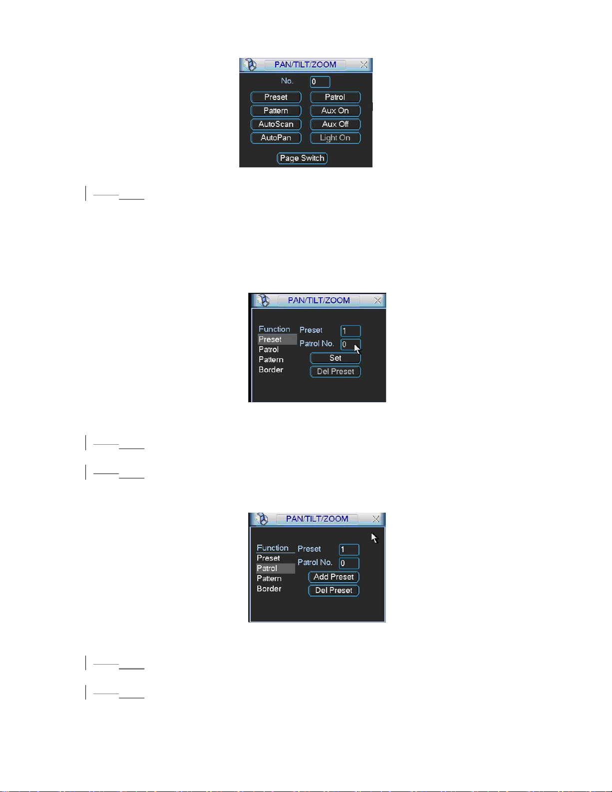
Figure 6-6
6.2.1 Preset Setup
5.2.1
Note: The following setups are usually operated in the 491HFigure 6-2, 492HFigure 6-5
and
493HFigure 6-6.
494HFigure 6-2, use eight direction arrows to adjust camera to the proper position.
In
In
495HFigure 6-5, click preset button and input preset number. The interface is shown as
496HFigure 6-7.
in
Add this preset to one patrol number
Figure 6-7
6.2.2 Activate Preset
5.2.2
In 497HFigure 6-6 please input preset number in the No. blank, and click preset button.
6.2.3 Patrol Setup
5.2.3
In 498HFigure 6-5, click patrol button. The interface is shown as in 499HFigure 6-8.
Input preset number and then add this preset to one patrol.
Figure 6-8
6.2.4 Activate Patrol
5.2.4
In 500HFigure 6-6, input patrol number in the No. blank and click patrol button
5.2.5
6.2.5 Pattern Setup
In 501HFigure 6-5, click pattern button and then click begin button. The interface shows
502HFigure 6-9.
like
74
Page 75
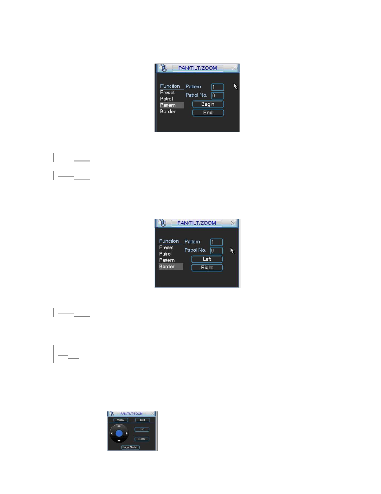
Please go to
503HFigure 6-2 to modify zoom, focus, and iris. Go back to 504HFigure 6-9 and
click end button.
You can memorize all these setups as pattern 1.
Figure 6-9
5.2.6
6.2.6 Activate Pattern Function
In 505HFigure 6-6 input mode value in the No. blank, and click pattern button.
6.2.7 Border Setup
5.2.7
In 506HFigure 6-5, click border button. The interface is shown as in 507HFigure 6-10.
Please go to
please go to
508HFigure 6-2, use direction arrows to select camera left limit, and then
509HFigure 6-10 and click left limit button
Repeat the above procedures to set right limit.
Figure 6-10
5.2.86.2.8 Activate Border Function
In 510HFigure 6-6, click auto scan button, the system begins auto scan. Correspondingly,
the auto scan button changes to stop button.
Click stop button to terminate scan operation.
6.3 Dome Menu Control
5.3
In 511HFigure 6-6, click page switch button, the interface is shows as below. See 512HFigure
6-11
Click menu to enter dome menu. The direction arrows here are to control dome
menu.
Click page switch button, system goes back to
513HFigure 6-2.
Figure 6-11
75
Page 76
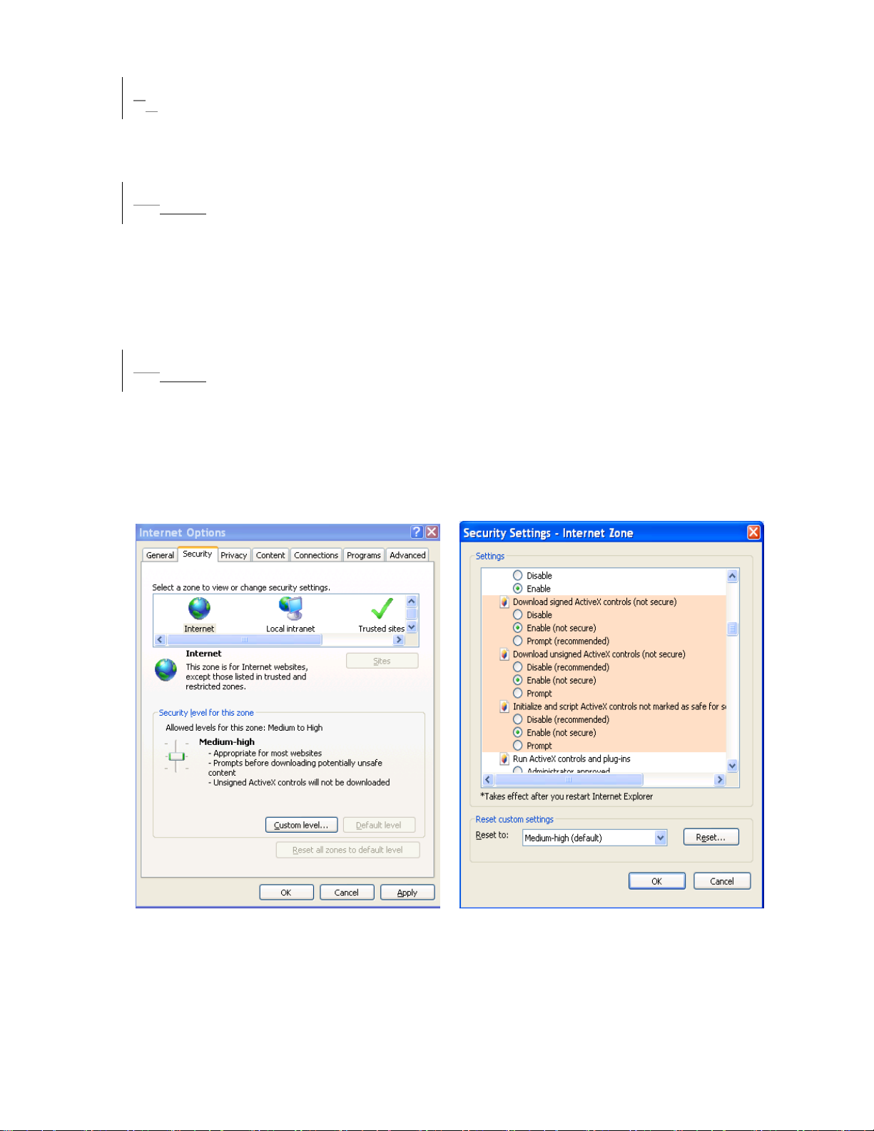
67 WEB CLIENT OPERATION
Please note, all the operation here in chapter seven is using 16-ch DVR as an
example.
There might be slightly difference in the interface due to different series.
6.17.1 Network connection
Before web client operation, please check the following items:
z Network connection is right
z DVR and PC network setup is right. Please refer to network setup(main menu-
>setting->network)
z Use order ping ***.***.***.***(* DVR IP address) to check connection is OK or not.
Usually the return TTL value should be less than 255.
6.27.2 Login and logout
Open IE and input DVR address in the address column. For example, if your DVR IP
is 10.1.27.200, then please input http:// 10.1.27.200 in IE address column.
System pops up warning information to ask you whether install webrec.cab control or
not. Please click yes button.
If you can’t download the ActiveX file, please modify your settings as follows.
514HFigure 7-1.
See
Figure 7-1
After installation, the interface is shown as below. See
515HFigure 7-2.
76
Page 77
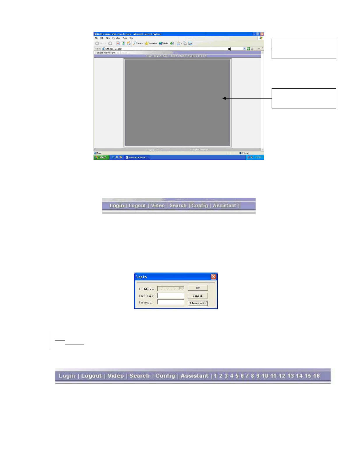
Input your IP
address here.
Video display
window
Figure 7-2
There are six function keys: login, logout, video, search, configuration and assistant.
See
516H
Figure 7-3.
Figure 7-3
517H
Click login the following interface will pop up. See
Figure 7-4. Please input your user
name and password.
Default factory name is admin and password is admin.
Note: For security reasons, please modify your password after you first login.
Figure 7-4
6.37.3 Go to Real-time Monitor Mode
There are three ways for you to go to real-time monitor mode.
518H
z Select the channel number besides function key. See
Figure 7-5.
z In
519H
Figure 7-5, click “video” button then select real-time monitor, click the channel
number you want to view.
Figure 7-5
Page 78
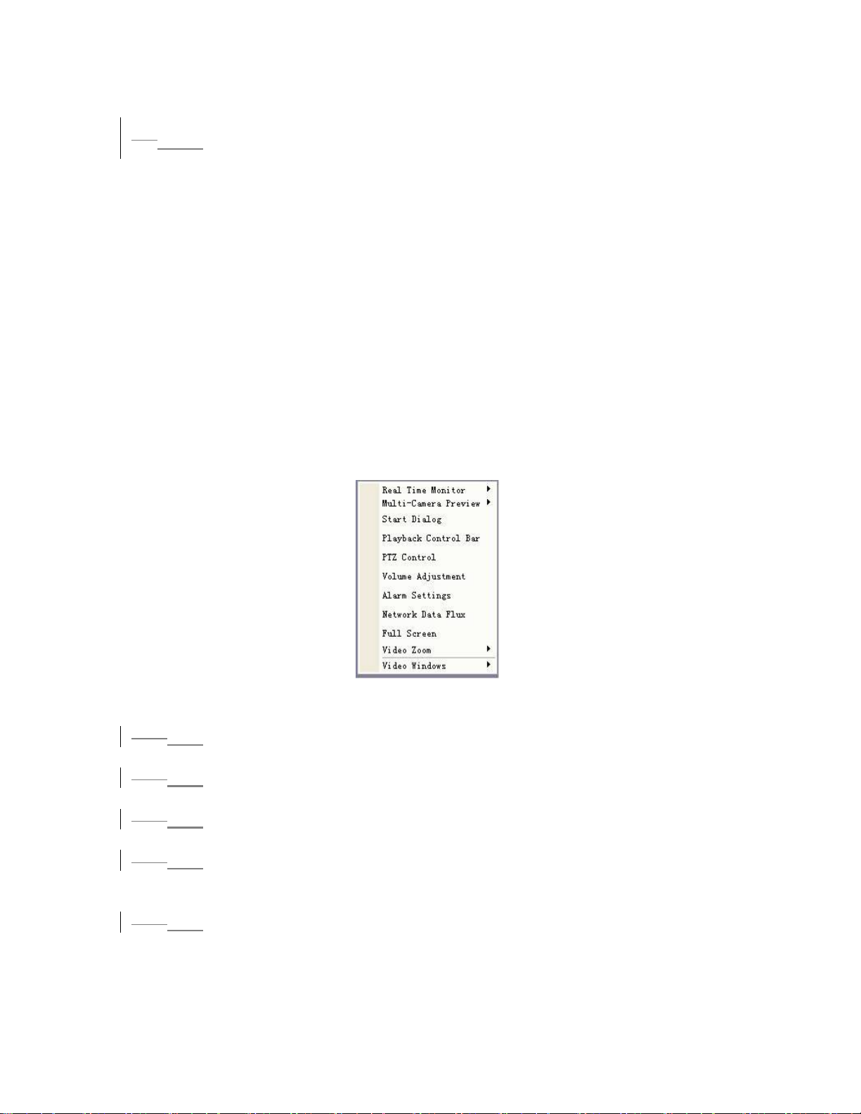
z In the main window, right click mouse, select the channel you want to view from
real-time monitor.
6.47.4 Video (Right Mouse Menu Operation)
After login, click video button or right click mouse, the interface is shown as below.
See
520HFigure 7-6.
z Real-time monitor: choose the channel you want to view.
z Start dialogue: click here to begin audio talk.
z Multi-camera preview: System supports various video preview modes.
z Decode quality: there are totally four levels: general, good, better and best.
z Playback control bar: here is for you to control playback.
z PTZ control: Here is for you to control PTZ movement. Before operate, please
make sure you have selected right pan-title protocol for DVR
z Volume adjustment: here is for you to adjust PC audio volume.
z Alarm setting: here is for you to set alarm input and alarm output.
z Network data flux: here is for you to view current data flux
z Full screen: enter into full screen display mode.
z Video zoom: there are four options:20%,40%,60%,80%,100%
z Video windows: Support 1/2/4 window display mode.
Figure 7-6
7.4.1 Real time Monitor
6.4.1
Here is for you to select the channel you wan to implement real-time monitor.
7.4.2 Multi-camera Preview
6.4.2
Here is for you to select view modes: 1/2/3/4/9/16.
6.4.3
7.4.3 Start Dialog
Click this button to enable audio talk function.
7.4.4 Decode Quality
6.4.4
Here is for you to select decode quality. There are totally four levels: general, good,
better and best.
7.4.5 Playback Control Bar
6.4.5
Here is the playback bar when you are viewing video file. See 521HFigure 7-7.
78
Page 79
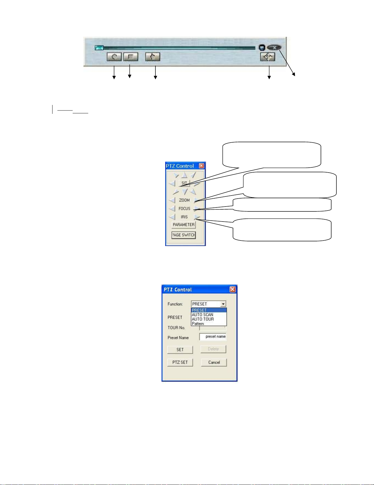
Record Stop Snapshoot Full-screen Close
Figure 7-7
6.4.6
7.4.6 PTZ Control
Please click the corresponding direction arrow to adjust zoom, focus and iris.
522H
Figure 7-8.
See
Note: before you operate this function, please make sure you have properly set PTZ
protocol (Main menu->Setting->Pan-tilt Zoom).
SIT is 3D positioning button. Around
SIT are eight PTZ directions keys.
Left key: zoom out. Right key: zoom
in.
Left key: zoom in. Right key: zoom out
Click parameter button in
7-9.
Left key: turn dark. Right key: turn
bright.
Figure 7-8
523H
Figure 7-8. The interface is shown as below. See
Figure 7-9
524H
Figure
Here is for you to control direction operation. There are eight levels ranging from 1 to
8. Level 8 is the fastest speed.
525H
Figure 7-9, click PTZ set button. You can see the following dialogue box.
In
526H
Figure 7-10. You can select in the dropdown list.
See
Page 80
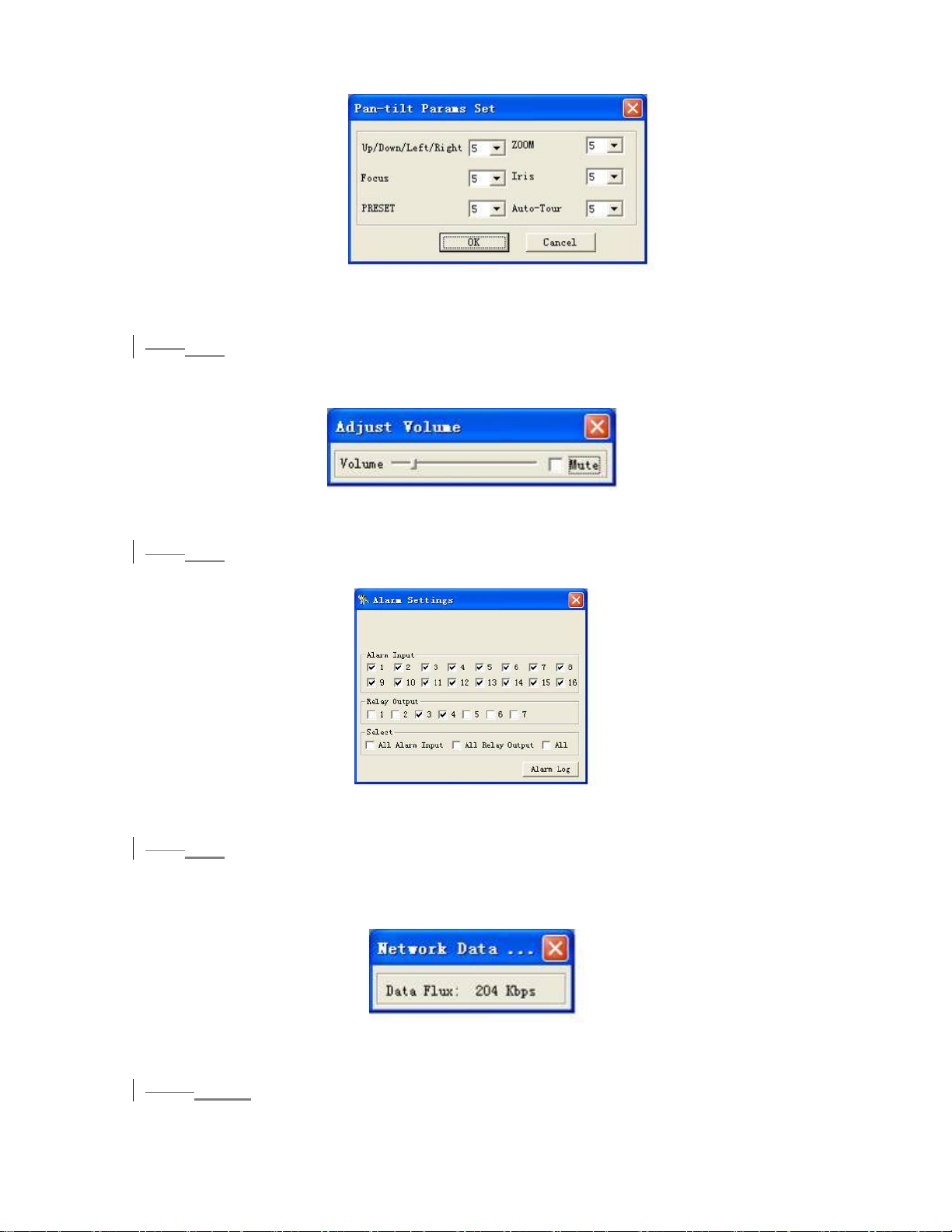
Figure 7-10
7.4.7 Volume Adjustment
6.4.7
Please drag volume bar to adjust audio level. You can draw a before Mute to turn
off audio. See
527HFigure 7-11.
Figure 7-11
6.4.8
7.4.8 Alarm Setting
Click alarm setting, you can set alarm input and output. See 528HFigure 7-12.
Figure 7-12
6.4.97.4.9 Network Data Flux
Here is to display the statistics of the network transmission data flux. See 529HFigure 7-13.
Figure 7-13
6.4.10
7.4.10 Full Screen
There are two ways to view full screen monitor: One is to double click on the current
monitor window directly; the other is to select Full screen in the right click menu items.
80
Page 81
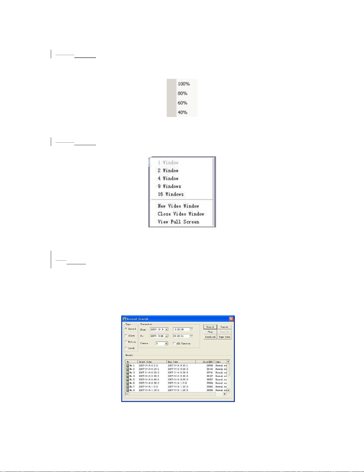
During multi-window state, choose one of the windows and double click for full screen
display.
6.4.11
7.4.11 Resize Video
There are four display ratios for you to choose: 40%, 60%, 80% and 100%.
530HFigure 7-14.
See
Figure 7-14
6.4.12
7.4.12 Video Windows
Here is for you to choose display mode. See 531HFigure 7-15.
Figure 7-15
6.57.5 Search
Here you can select video type, channel number and time to search the file you want.
Click search button, the interface is shown as below. See
Please use page up/down key to view the search results.
Double click file name, you can view the file and system will automatically backup
the image in you installation directory.
532HFigure 7-16
Figure 7-16
81
Page 82
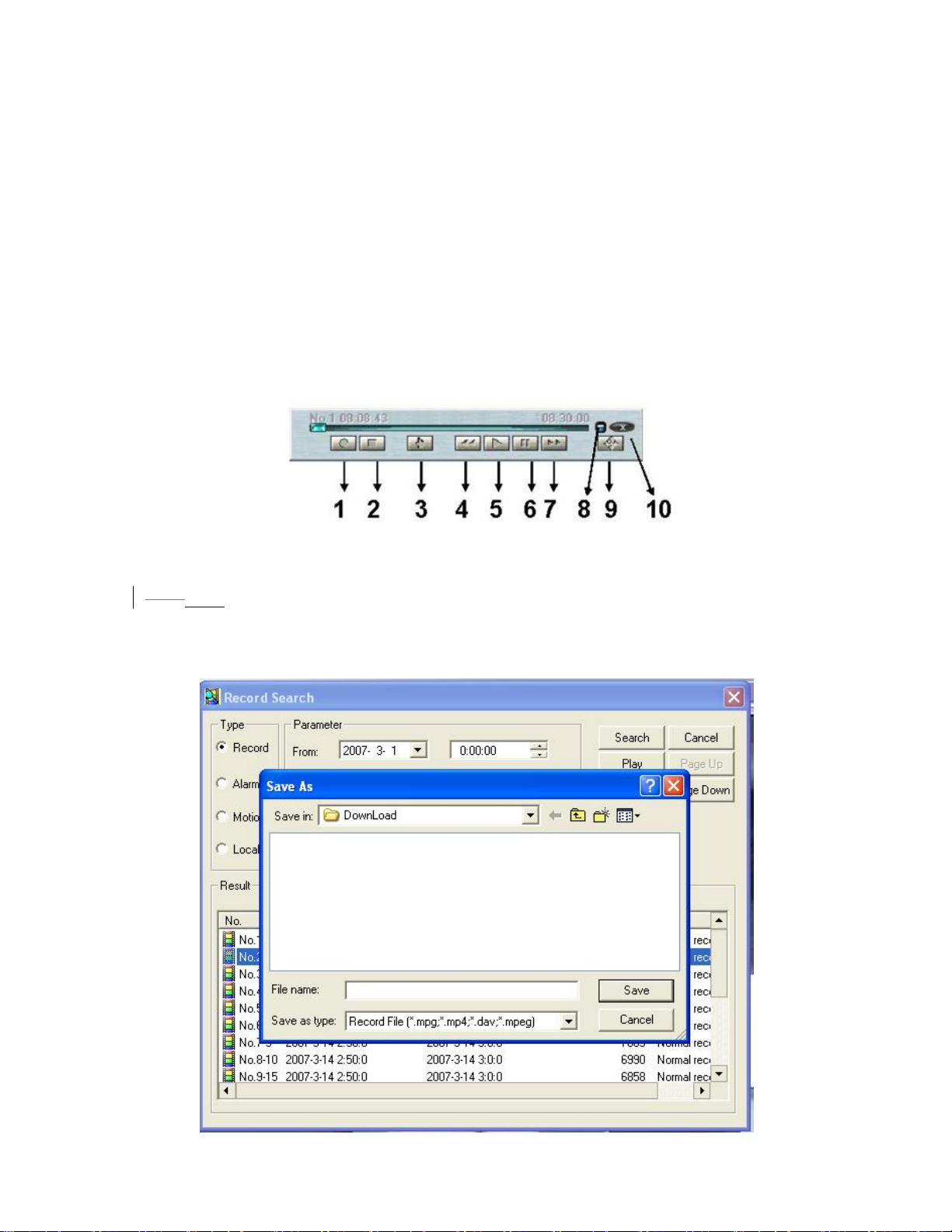
In the search result interface, you can select one or more files to download to your
local PC.
The playback bar is shown as below. See
533HFigure 7-17.
1: Save
2: Stop
3: Snapshoot
4: Fast Backward
5: Play
6: Pause
7: Fast play
8: Hide
9. Full-screen
10. Close
Figure 7-17
6.5.1
7.5.1 Download
You can select one or more files you want to download and then click down load
button. System pops up a dialogue box asking you specify directory. See
534HFigure
7-18.
82
Page 83
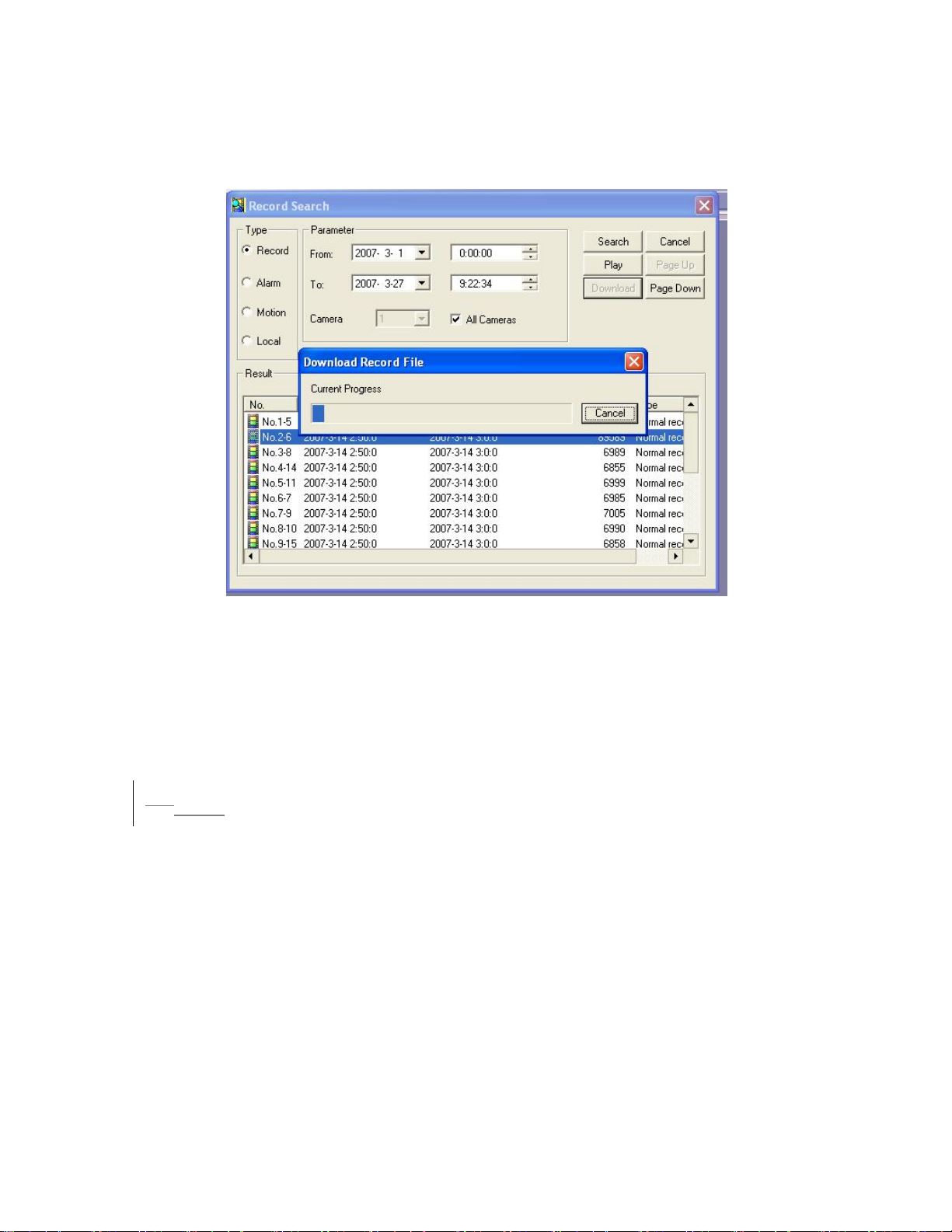
Figure 7-18
Then you can input file name and click save to backup file in your local pc.
During the download process, there is a process bar for you reference. See
7-19.
535HFigure
Figure 7-19
Download file name is usually made up of: file name +Channel N +date +time.
File extension name is .dav.
For example: file name a-0120021205071028.mp4 means:
z 01: channel 1
z 20021205: 5
th
December,2002
z 071028 :7 o’clock 10 minutes 28 seconds.
6.67.6 Configure
Click configure button, there are totally seven function keys. See 536HFigure 7-20.
z Image
z Alarm
z Motion detection
z Network
z Video parameter
z General
z Schedule
83
Page 84
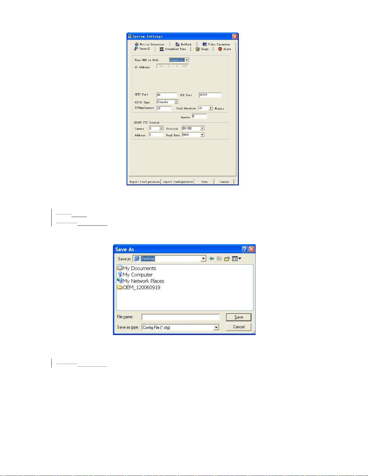
Figure 7-20
7.6.1 Load and Save Configuration
6.6.1
6.6.1.17.6.1.1 Save configuration
Click export configuration button in 537HFigure 7-20.You can save current configuration to
a directory. The file extension name is CFG. See
538HFigure 7-21.
Figure 7-21
6.6.1.2
7.6.1.2 Load configuration
Click import configuration button in 539HFigure 7-20.You can draw a before checkbox to
load you previously backup file. See
540HFigure 7-22.Click Ok button and then select file
of extension name .CFG. Now you have updated system setup.
84
Page 85
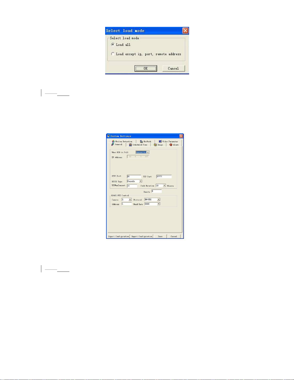
Figure 7-22
6.6.2
7.6.2 General
Click general button, the interface is shown as below. See 541HFigure 7-23.
Here you can select file length, and choose overwrite the previous file or stop
recording when disk is full.
You can select channel number, protocol, address and baud rate to control the lens
or PTZ.
Figure 7-23
6.6.3
7.6.3 Schedule
Click schedule button, the interface is shown as in 542HFigure 7-24.
Here you can draw a before Sunday to Saturday. And then set various time
periods (from 0 to 24 o’clock).
You can draw a to enable record type: record/motion/alarm.
85
Page 86
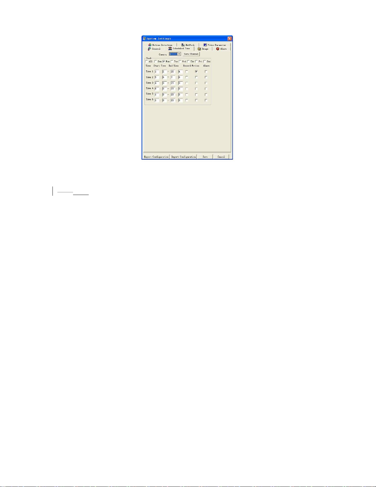
Figure 7-24
7.6.4 Image
6.6.4
Click image button, the interface is shown as below. See 543HFigure 7-25.
Here you can select the image quality and protocols for each channel.
Here you can set encode mode, quality and protocol for each channel. You can
select from the dropdown list.
z FPS (PAL): there are several options: 1/2/3/6/12/25. (Some series DVR only
support 25f/s PAL.)
z Data: there are two data modes: CBR/VBR.
z Quality: There are six levels. The different data flux occupies different bandwidth
and the transmission image qualities are also different. Among them, level 6
needs the widest bandwidth and can reveal the best image quality. Please note
you setup here only applies for image quality in web or client end.
z Resolution: there are several resolutions for you. You can select from the
dropdown list.
z Alarm when video loss: You can enable or disable alarm function when alarm
loss occurred.
z Network transmission protocol: Select protocol for network playback and monitor.
You can select from the dropdown list.
86
Page 87
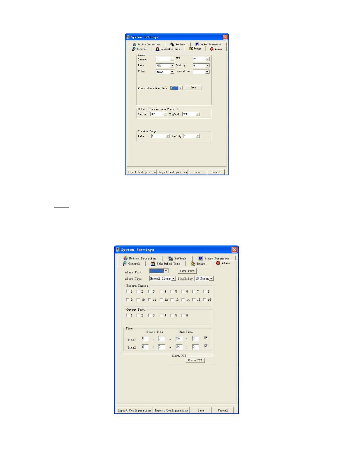
Figure 7-25
7.6.5 Alarm
6.6.5
Here is for you to choose record channel and output port. See 544HFigure 7-26.
There are two alarm types: normal open or normal close.
Delay time ranges from 10 to 300 seconds.
You can draw a before the check box to enable record camera and output port.
87
Page 88
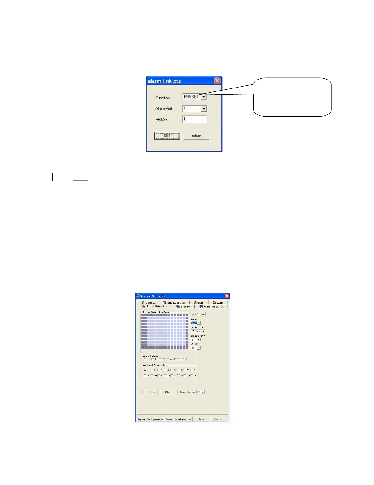
Figure 7-26
In
545H
Figure 7-26 click alarm PTZ button, you can see the following interface.
546H
Figure 7-27.
See
There are three options:
preset, auto scan and tour.
Figure 7-27
7.6.6 Motion Detection
6.6.6
Motion detection will take effect exclude the time you set to schedule recording.
547H
Figure 7-28.
See
The blue area is the selected motion detection area.
Click Full screen or right click mouse to view the motion detection area in full screen.
After setting the area you can Save channel or Clear the area.
Alarm output:Here you can enable alarm output channel. Please draw a √ before
the check box.
Please note if you want to set this channel as motion detection recording, you need
to turn off the schedule recording setup for this channel (Main Menu->Setting>Schedule).
Figure 7-28
Page 89
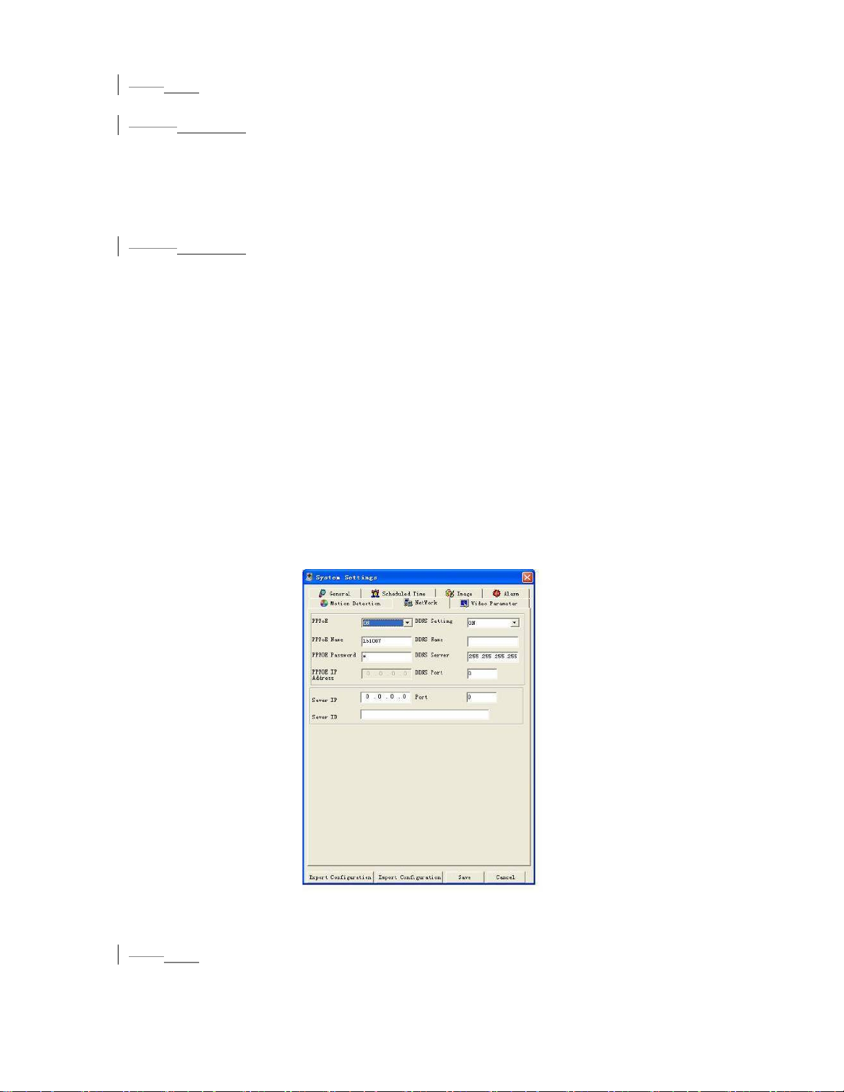
7.6.7 Network
6.6.7
Network interface is shown as in 548HFigure 7-29.
6.6.7.1
Set PPPOE as on, and then please input “PPPoE name” and “PPPoE password” you
get from your ISP (Internet service provider).
After saving it, you need to restart to active your configuration.
After rebooting, IP camera will connect to internet automatically. The IP in the
PPPoE IP is the dynamic value.
6.6.7.2
There are two ways.
After IP camera connected with Internet by PPPoE, please get your device’s current
IP. Now you can visit this IP camera via this IP.
You need a PC of fixed IP in the internet and there is the DDNS software running in
this PC. In other words, this PC is a DNS (domain name server).
In network DDNS, input your PPPoE name you get from you IPS and server IP (PC
with DDNS ) . Click save and then reboot system.
Click save button, system prompts for rebooting to get all setup activated.
After rebooting, open IE and input as below:
http://(DDNS server IP)/(virtual directory name)/webtest.htm
e.g.: http://10.6.2.85/DVR _DDNS/webtest.htm.)
Now you can open DDNSServer web search page.
7.6.7.1 PPPoE Connection
7.6.7.2 Web visit via PPPoE
c. visit through current IP
d. Visit via DNS
Figure 7-29
6.6.8
7.6.8 Video Parameter
Video parameter setup interface is shown as in 549HFigure 7-30. Before setup please
select channel number first
89
Page 90
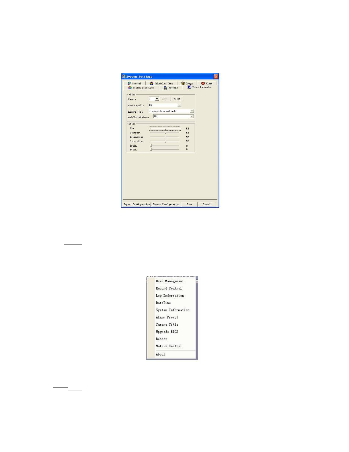
z Audio enable: You can select to close or open audio.
z Auto white balance: You can select to close or open white balance.
z Image: You can adjust color, contrast, brightness, saturation and etc.
After finishing all channels setup, you can click “save” at the button to save all
configurations.
Figure 7-30
6.77.7 Assistant
Click assistant setting, the interface is shown as below. See 550HFigure 7-31. There are
nine function keys.
Please note Matrix control item only applies for some special series.
Figure 7-31
7.7.1 User Manage
6.7.1
Here is for you to manage users and user groups. See 551HFigure 7-32. You can click ’+’
to see the whole group list.
90
Page 91
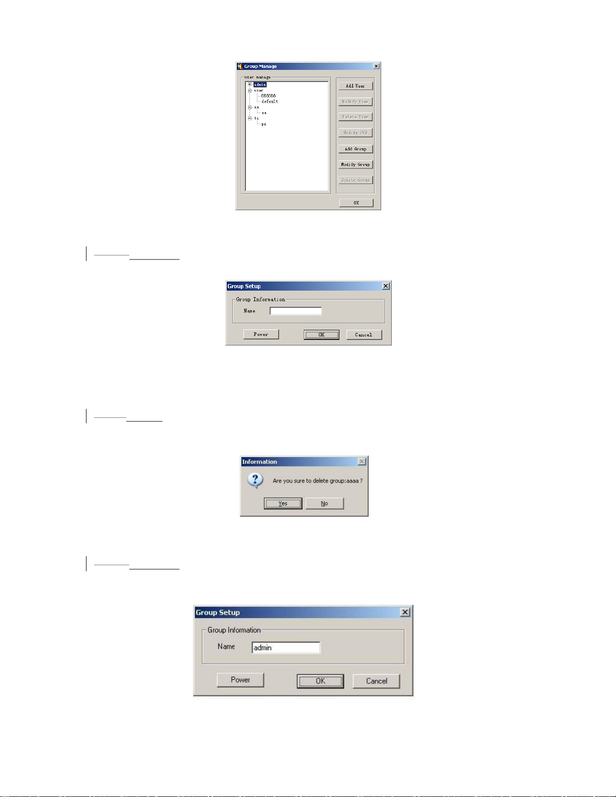
Figure 7-32
6.7.1.17.7.1.1 Add Group
Click “add group” button to input group name. See 552HFigure 7-33.
Figure 7-33
Click “Power” button to set group power.
Click “Save” button to save configuration
6.7.1.27.7.1.2 Delete Group
Click “Delete Group” button, the interface is shown as in 553HFigure 7-34.
Note: You can only delete empty group (E.g.: There is no user in current group).
Figure 7-34
6.7.1.3
7.7.1.3 Modify Group
Click modify group, the interface is shown as in 554HFigure 7-35. You can modify group
name and then click “power” button to set proper right for the whole group.
Figure 7-35
91
Page 92
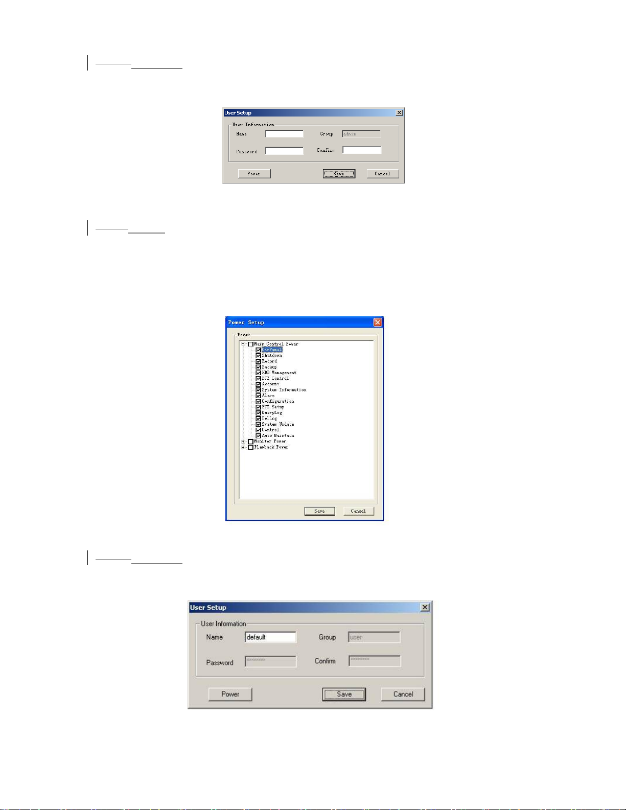
6.7.1.4
7.7.1.4 Add User
Click “Add User” button the interface is shown as in 555HFigure 7-36.
Input user name, password, and then input password again to confirm.
Figure 7-36
6.7.1.57.7.1.5 Power
When you add new user or new group (such as in 556HFigure 7-33,557HFigure 7-36. ), click
“power” button, the interface is shown as in
558HFigure 7-37. Here is for you to set user’s
power.
There are three power groups: main control power/monitor power/playback power.
You can draw a √ before the checkbox to enable corresponding function.
Figure 7-37
6.7.1.6
7.7.1.6 Modify user
Select one user and then click modify user button, the interface is shown as in 559HFigure
7-38. Here you can modify user name.
Figure 7-38
92
Page 93
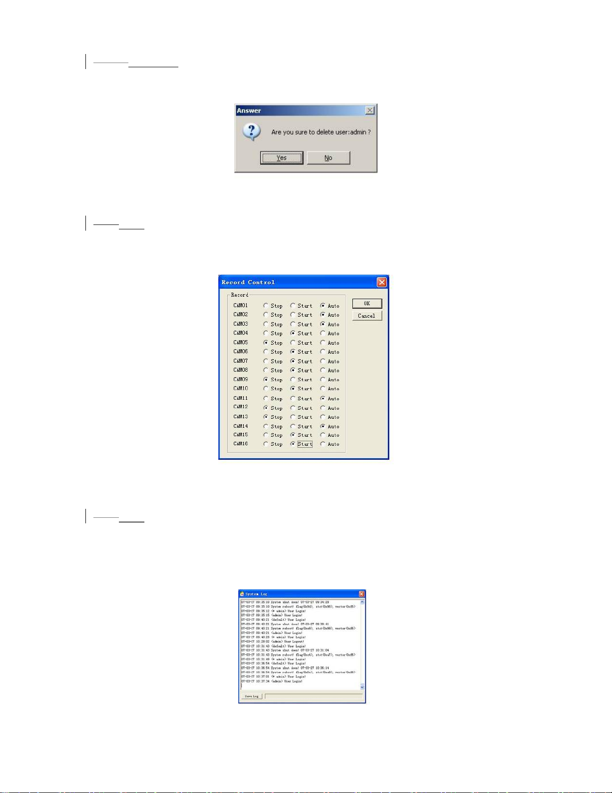
6.7.1.7
7.7.1.7 Delete user
Select one user and then click “delete user” button, you can see the following dialogue
box. See
560HFigure 7-39. Click “Yes” to delete current user.
Figure 7-39
6.7.27.7.2 Record Control
Click “record control” button the interface is shown as below. See 561HFigure 7-40. You
can select mode for each channel.
Figure 7-40
6.7.3
7.7.3 Log Information
System can automatically backup all operation in log information.
You can click this button to view detailed information. See
562HFigure 7-41.
Once you click save log button, the log files will be automatically saved in the root
directory such as “C:\ as a text file (e.g.: C:\ 10.1.27.193-log.txt)
Figure 7-41
93
Page 94

7.7.4 Date and Time
6.7.4
Here you can modify system date and time. See 563HFigure 7-42.
Figure 7-42
7.7.5 System Information
6.7.5
Here you can view basic information of the system. See 564HFigure 7-43.
Here you can
z Turn on/off audio
z Select video type
z Select preview image
z Preview image
z Close or open auto tour monitoring
z View network data flux
Figure 7-43
6.7.6
7.7.6 Alarm Prompt
Here is for you to choose different alarm audios. See 565HFigure 7-44.
Here you can select system AlarmSound.wav file from folder system32 as your audio
sound.
94
Page 95
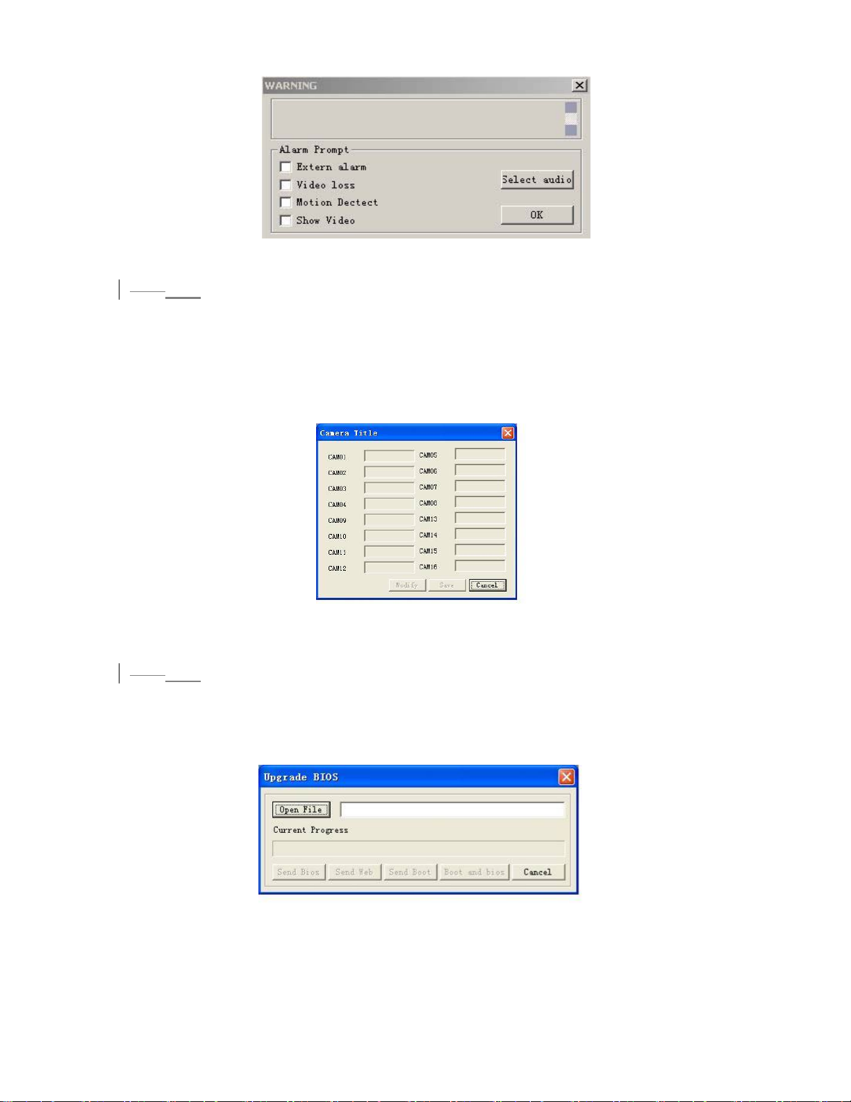
Figure 7-44
7.7.7 Channel Name
6.7.7
Here is for you to modify channel name.
The revised channel names will be displayed on the screen.
The default setting of the channel name is Channel No.1 to Channel No.16.
566HFigure 7-45.
See
Please note when you modify channel name in DVR end, this modification not
applies to web end or standalone end, you need to use this interface to refresh.
Figure 7-45
6.7.8
7.7.8 Upgrade BI O S
Click upgrade BIOS button, the interface is shown as below. See 567HFigure 7-46.
Open the BIOS file (You can get from our local engineer or download from our web
service) and then click send BIOS button.
During the upgrade process, there is a process bar for your reference.
Figure 7-46
95
Page 96
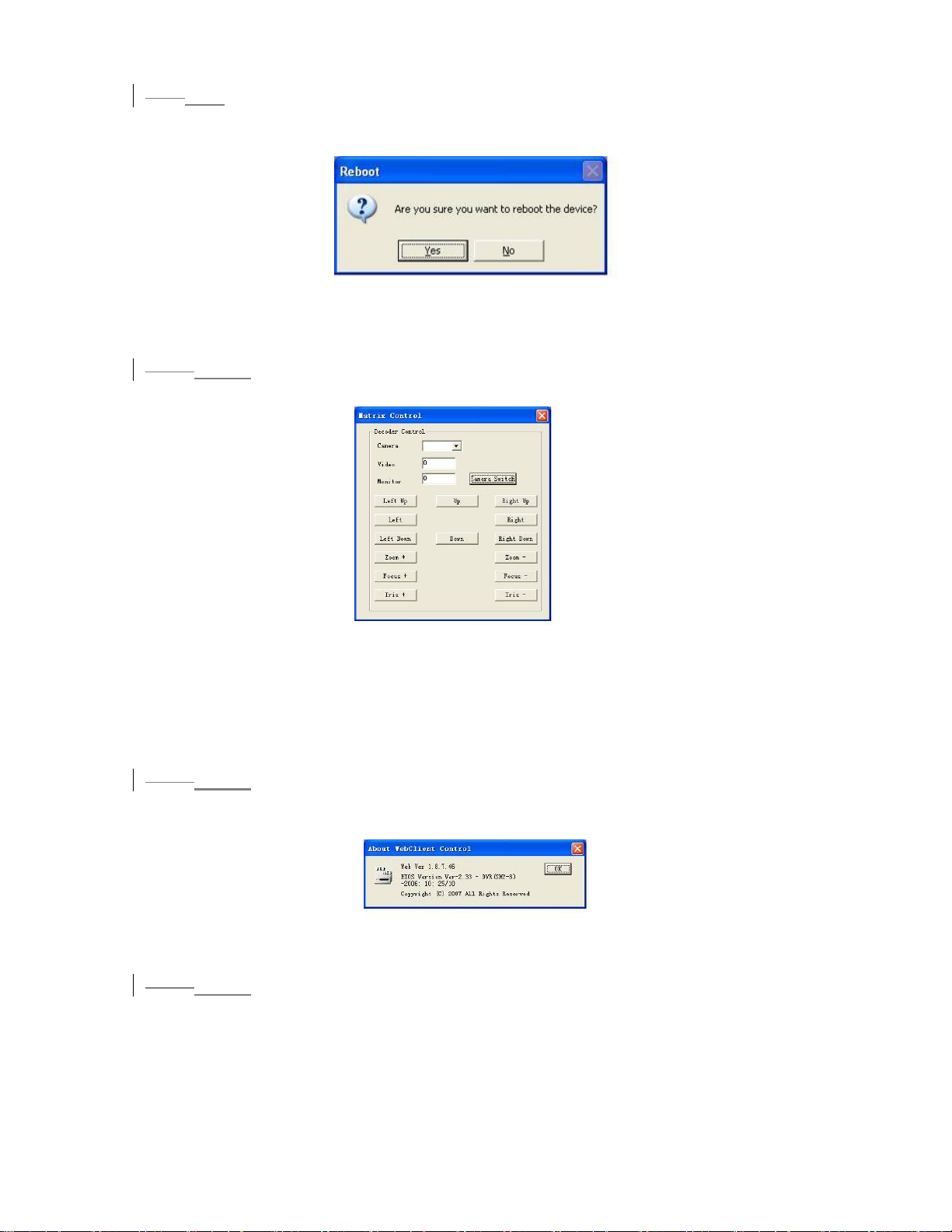
7.7.9 Reboot
6.7.9
Click reboot button, system pops up a warning dialogue box to alert you.
568HFigure 7-47.
See
Figure 7-47
6.7.10
7.7.10 Matrix (Applies for some special series only)
Matrix control interface is shown as in 569HFigure 7-48.
Figure 7-48
This feature is not available in LN-S model.
6.7.11
Here is for you to view basic system information. See 570HFigure 7-49.
6.7.12
In the assistant setup, select email function. You can see the interface is shown as
in
Here you can input server IP, receiver, email title and etc.
7.7.11 About
Figure 7-49
7.7.12 Mail
571HFigure 7-50.
96
Page 97
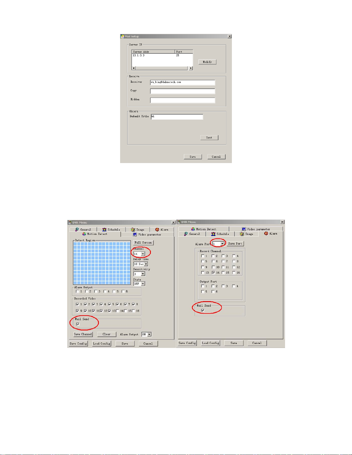
Figure 7-50
Now you can set alarm information for future upload.
For motion detection, you can enable email function in detection interface.
For external alarm, you can enable email function in alarm setup interface.
572HFigure 7-51.
See
Figure 7-51
After setup, you can receive email form client end.
The email content is shown as below:
Alarm Matter: Email Test...
AlarmIn Channel: 255
Alarm Start Date(Day/Month/Year Hour:Minute:Second): 12/12/2006 16:30:20
Alarm Device Name: localhost
97
Page 98

Mail_Sender IP : 10.6.3.8
In motion detection mode, you can set email function (Enable/disable) for each
channel.
The email content is shown as below.
Alarm Matter: Motion Detect
AlarmIn Channel: 2
Alarm Start Date(Day/Month/Year Hour:Minute:Second): 12/12/2006 15:5:36
Alarm Device Name: localhost
Mail_Sender IP : 10.6.3.9
6.87.8 Un-install Web Control
There are three ways for you to un-install web control.
z From start, click run and then input order regsvr32 -u WebRec.ocx.
z Use web un-install tool “uninstall web.bat” to un-install web control.
98
Page 99
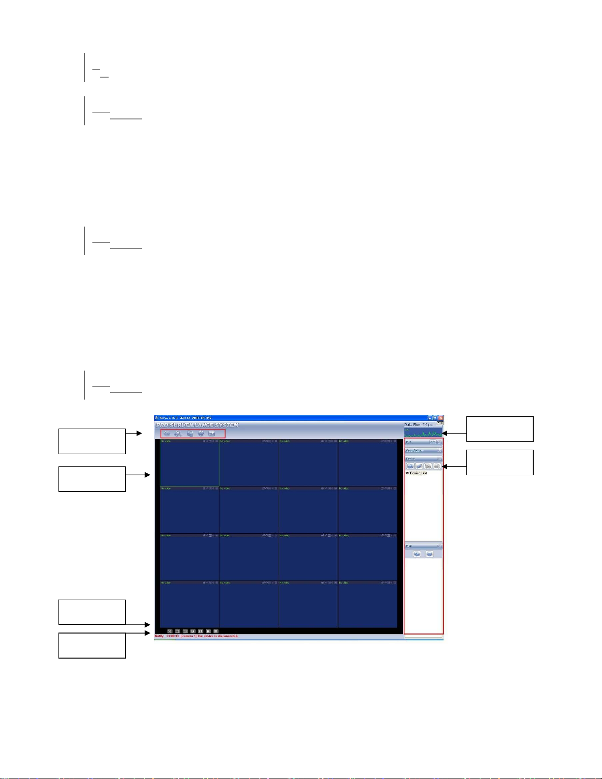
78 Pro Surveillance System
Professional surveillance system allows you to manage a lot of DVRs remotely.
7.18.1 Features
Professional surveillance system has the following features:
z Manage devices conveniently
z Support multiple-device connection, real-time surveillance and playback
z Device management, log review and user management
z PTZ control and device alarm, video record
z Support multiple-device upgrade simultaneously
z E-map and network backup support
7.28.2 Environment
We recommend the following configuration:
Hardware
z CPU P4 2.0G
z Display card: support hardware zoom such as ATI,TNT2 PRO. We recommend
ATI9800 or above dual channel. 128M/128bit
z Network card: 100M
Software
z For client end we recommend Windows 2000 or Windows XP.
7.38.3 Overview
Multiple-client main window is shown as in
Section 1
Section 2
Section 3
Section 4
573H
Figure 8-1.
Figure 8-1
Section 5
Section 6
There are totally six sections:
z Section 1: There are five function keys: monitor, record, device, system and e-
map.
Page 100

z Section 2: Here is for you to view channel video.
z Section 3: Here is for you to select display mode. System supports the following
display modes: full-screen /single window/four-window/six-window/eight-
window/nine-window/sixteen-window.
z Section 4: Here is for you to view current help information.
z Section 5: Here is to display data flux and CPU status.
z Section 6: There are four function buttons: PTZ/Color setting/Device/Plan.
7.48.4 More Details
Please refer to the Professional Surveillance System User’s Manual for more
information.
.
100
 Loading...