

Videovox Pro DVR User Manual

ATM Series-Standalone DVR
User’s Manual
1

Table of Contents
1 FEATURES AND SPECIFICATIONS ................................................................. 11
1.1 Features ................................................................................................................................................ .... 11
1.2 Specifications............................... ............................. ............................ ................................................... 11
2 OVERVIEW AND CONTROLS ........................................................................... 14
2.1 Front Panel ............................................................................................................................................... 14
2.2 Rear Panel ...................................... .......................... ......................... ............................. ....................... .. 16
2.2.1 Overview .............................................................................................................................................. 16
2.2.2 Connection Sample ........................................................................................................................... 17
2.3 Remote Control ................ ................................... ..................................... .................................... ........... 18
2.4 Mouse Control .................................... ................................. ................................. ................................. .. 19
2.5 Virtual Keyboard & Front Panel ............................................................................................................ 20
2.5.1 Virtual Keyboard Input Method ........................................................................................................ 20
2.5.2 Front Panel Input Method ................................................................................................................. 20
3 INSTALLATION AND CONNECTIONS .............................................................. 21
3.1 Check Unpacked DVR ........................................................................................................................... 21
3.2 HDD Installation .................................... ............................ ............................ ............................... ........... 21
3.2.1 Choose HDDs ..................................................................................................................................... 21
3.2.2 Calculate HDD Size ........................................................................................................................... 21
3.2.3 HDD Installation ................................................................................................................................. 21
3.3 CD/DVD Burner Installation ..................................... ..................................... ...................................... .. 22
2

3.4 Desktop and Rack Mounting ........................................ .... ..... ..... ....... .... ..... ..... ....... ..... .... ..... ....... ..... .... 23
3.4.1 Desktop Mounting .............................................................................................................................. 23
3.4.2 Rack Mounting .................................................................................................................................... 23
3.5 Connecting Power Supply ..................................................................................................................... 23
3.6 Connecting Video Input and Output Devices .......................................... ............ ......... .......... ......... .. 23
3.6.1 Connecting Video Input .................................................................................................................... 23
3.6.2 Connecting Video Output ................................................................................................................. 24
3.7 Connecting Audio Input & Audio Output, Alarm Input &Alarm Output, RS232/RS485 and
Other Interfaces ........................... ........................................... ....................................... ........................................ 25
3.7.1 Audio Input/Audio Output ................................................................................................................. 25
3.7.2 Alarm Input and Relay Output ......................................................................................................... 25
3.7.3 Alarm Input .......................................................................................................................................... 25
3.7.4 Alarm Output ....................................................................................................................................... 26
3.7.5 Alarm Input and Output Details ....................................................................................................... 26
3.7.6 Relay Output Description .................................................................................................................. 28
3.8 RS232 ......................................... ............................... ................................ ............................... ................ 29
3.9 RS485 ......................................... ............................... ................................ ............................... ................ 29
3.10 Other Interfaces .................................... ....... ....... ......... ....... ....... .......... ....... ....... ....... ......... ....... ....... ....... 30
4 OVERVIEW OF NAVIGATION AND CONTROLS ............................................. 31
4.1 Login, Logout & Main Menu .................................................................................................................. 31
4.1.1 Login ..................................................................................................................................................... 31
4.1.2 Main Menu ........................................................................................................................................... 31
4.1.3 Logout .................................................................................................................................................. 32
4.1.4 Auto Resume after Power Failure ................................................................................................... 32
4.1.5 Replace Button Battery ..................................................................................................................... 32
4.2 Recording Operation ....................................... ........................................... ........................................ .... 32
4.2.1 Live Viewing ........................................................................................................................................ 32
4.2.2 Manual record ..................................................................................................................................... 33
3

4.3 Search & Playback .............. ............................. ............................ .............................. ............................ 35
4.3.1 Search Menu ....................................................................................................................................... 35
4.3.2 Basic Operation .................................................................................................................................. 36
4.3.3 Calendar .............................................................................................................................................. 37
4.4 Record Setup (Schedule) ...................................................................................................................... 38
4.4.1 Schedule Menu ........................................................................................................................................ 38
4.4.2 Basic Operation ....................................................................................................................................... 38
4.5 Motion Detect.................................. ............................ ............................ ................................................. 40
4.5.1 Go to Motion Detect Menu ..................................................................................................................... 40
4.5.2 Motion Detect ........................................................................................................................................... 40
4.5.3 Video Loss ................................................................................................................................................ 41
4.5.4 Camera Mask Detect .............................................................................................................................. 42
4.6 Alarm Setup and Alarm Activation ....................................................................................................... 43
4.6.1 Go to alarm setup interface .............................................................................................................. 43
4.6.2 Alarm setup ......................................................................................................................................... 43
4.7 Backup ..................... ............................................. ............................................... ..................................... 44
4.7.1 Detect Device .......................................................................................................................................... 44
4.7.1 Backup ................................................................................................................................................. 44
4.8 PTZ Control and Color Setup .................................... ................................... .................................... .... 46
4.8.1 Cable Connection .................................................................................................................................... 46
4.8.2 PTZ Setup ................................................................................................................................................ 46
4.8.3 3D Intelligent Positioning Key .............................................................................................................. 47
4.9 Preset/ Patrol/Pattern/Scan ............................ ....................... ..................... ..................... ..................... 47
4.9.1Preset Setup ............................................................................................................................................. 48
4.9.2 Activate Preset ........................................................................................................................................ 49
4.9.3 Patrol Setup (Tour setup) ...................................................................................................................... 49
4.9.4 Activate Patrol (tour) .............................................................................................................................. 49
4.9.5 Pattern Setup .......................................................................................................................................... 49
4.9.6 Activate Pattern Function ...................................................................................................................... 50
4.9.7 Auto Scan Setup ..................................................................................................................................... 50
4.9.8 Activate Auto Scan ................................................................................................................................. 50
4.10 Dome Menu Control ......................................... ............................................... ..................................... 50
4

UNDERSTANDING OF MENU OPERATIONS AND CONTROLS .................... 51
5
5.1 Menu Tree ................................................................................................................................................ 51
5.2 Main Menu ............................... ....... .... ..... ....... ..... ..... .... ....... ..... ..... ....... .... ..... ....... ..... ..... .... ..................... 51
5.3 Setting ...................... .................................................... .................................................... ......................... 52
5.3.1 General ................................................................................................................................................ 52
5.3.2 Encode ................................................................................................................................................. 53
5.3.3 Schedule .............................................................................................................................................. 54
5.3.4 RS232 .................................................................................................................................................. 54
5.3.5 Network ................................................................................................................................................ 55
5.3.6 Alarm .................................................................................................................................................... 60
5.3.7 Detect ................................................................................................................................................... 60
5.3.8 Pan/Tilt/Zoom ..................................................................................................................................... 60
5.3.9 Display ................................................................................................................................................. 60
5.3.10 Default ............................................................................................................................................. 61
5.4 Search .................................................................................................................................. ..................... 62
5.5 Advanced............................................................................................................. ............................ ......... 62
5.5.1 HDD Management ............................................................................................................................. 62
5.5.2 Alarm Output ....................................................................................................................................... 63
5.5.3 Alarm Input .......................................................................................................................................... 64
5.5.4 Manual Record ................................................................................................................................... 64
5.5.5 Account ................................................................................................................................................ 64
5.5.6 Auto Maintain ...................................................................................................................................... 65
5.5.7 TV Adjust ............................................................................................................................................. 65
5.6 Information ........................ ............................ .......................... ......................... ............................. ........... 66
5.6.1 HDD Information ................................................................................................................................ 66
5.6.2 BPS ....................................................................................................................................................... 67
5.6.3 Log ........................................................................................................................................................ 67
5.6.4 Version ................................................................................................................................................. 67
5.6.5 Online Users ....................................................................................................................................... 68
5.7 Exit .................................................................................................................................... ......................... 68
6 ABOUT AUXILIARY MENU .......................................................... ...................... 70
5

6.1 Go to Pan/Tilt/Zoom Menu .................................................................................................................... 70
6.1.1 3D Intelligent Positioning Key .......................................................................................................... 70
6.2 Preset /Patrol / Pattern /Border Function .................................................... ..................................... 71
6.2.1 Preset Setup ....................................................................................................................................... 72
6.2.2 Activate Preset ................................................................................................................................... 72
6.2.3 Patrol Setup ........................................................................................................................................ 72
6.2.4 Activate Patrol..................................................................................................................................... 72
6.2.5 Pattern Setup ...................................................................................................................................... 72
6.2.6 Activate Pattern Function ................................................................................................................. 73
6.2.7 Border Setup ....................................................................................................................................... 73
6.2.8 Activate Border Function .................................................................................................................. 73
6.3 Dome Menu Control ........ .............................. ............................ ............................... ............................ .. 73
7 WEB CLIENT OPERATION ................................................................................ 74
7.1 Network connection ................................................................................................................................ 74
7.2 Login and logout............................... ............................ ........................................................................... 74
7.3 Go to Real-time Monitor Mode ............. ...................................... ..................................... ..................... 75
7.4 Video (Right Mouse Menu Operation) ............................... ............................ .............................. ....... 76
7.4.1 Real time Monitor ............................................................................................................................... 76
7.4.2 Multi-camera Preview ........................................................................................................................ 76
7.4.3 Start Dialog ......................................................................................................................................... 76
7.4.4 Decode Quality ................................................................................................................................... 76
7.4.5 Playback Control Bar ......................................................................................................................... 76
7.4.6 PTZ Control ......................................................................................................................................... 77
7.4.7 Volume Adjustment ........................................................................................................................... 78
7.4.8 Alarm Setting ...................................................................................................................................... 78
7.4.9 Network Data Flux ............................................................................................................................. 78
7.4.10 Full Screen ..................................................................................................................................... 78
7.4.11 Resize Video .................................................................................................................................. 79
7.4.12 Video Windows .............................................................................................................................. 79
7.5 Search .................................................................................................................................. ..................... 79
7.5.1 Download ............................................................................................................................................. 80
6

7.6 Configure .................................... ................................................. .................................................. ........... 81
7.6.1 Load and Save Configuration .......................................................................................................... 82
7.6.2 General ................................................................................................................................................ 83
7.6.3 Schedule .............................................................................................................................................. 83
7.6.4 Image ................................................................................................................................................... 84
7.6.5 Alarm .................................................................................................................................................... 85
7.6.6 Motion Detection ................................................................................................................................ 86
7.6.7 Network ................................................................................................................................................ 87
7.6.8 Video Parameter ................................................................................................................................ 87
7.7 Assistant ..................... ..................................... ........................................ ...................................... ........... 88
7.7.1 User Management ............................................................................................................................. 88
7.7.2 Record Control ................................................................................................................................... 91
7.7.3 Log Information .................................................................................................................................. 91
7.7.4 Date and Time .................................................................................................................................... 91
7.7.5 System Information ............................................................................................................................ 92
7.7.6 Alarm Prompt ...................................................................................................................................... 92
7.7.7 Camera Title ....................................................................................................................................... 93
7.7.8 Upgrade BIOS .................................................................................................................................... 93
7.7.9 Reboot .................................................................................................................................................. 93
7.7.10 About ............................................................................................................................................... 93
7.7.11 Mail (Applies for Special Series Only) ....................................................................................... 94
7.8 Un-install Web Control ........................................................................................................................... 95
8 PRO SURVEILLANCE SYSTEM ........................................................................ 96
8.1 Features ................................................................................................................................................ .... 96
8.2 Environment ...................................................................................................................................... ....... 96
8.3 Overview .......................................................................................................................................... ......... 96
8.4 More Details ............................................................................................................................................. 97
9 RS232 OPERATION ........................................................................................... 98
9.1 Network Connection .......................... .................................................. ................................................... 98
7

9.2 Keyboard .................... .............................. ............................ ............................ ............................. ........... 98
10 FAQ ..................................................................................................................... 99
APPENDIX A HDD CAPACITY CALCULATION ................................................... 101
APPENDIX B COMPATIBLE USB DRIVE LIST .................................................... 102
APPENDIX C COMPATIBLE CD/DVD BURNER LIST ......................................... 103
APPENDIX D COMPATIBLE IDE HDD LIST ........................................................ 104
APPENDIX E COMPATIBLE SATA HDD LIST ..................................................... 105
8

Welcome
Thank you for purchasing our DVR!
This operating manual is designed to be a reference tool for the installation and
operation of your system.
Here you can find information about this series DVR features and functions, as well
as a detailed menu tree.
Before installation and operation please read the following safeguards and warnings
carefully!
9

Important Safeguards and Warnings
1.Electrical safety
All installation and operation here should conform to local electrical safety codes.
We assume no liability or responsibility for all the fires or electrical shock caused by
improper handling or installation.
2.Transportation security
Heavy stress, violent vibration or water splash are not allowed during transportation,
storage and installation.
3.Installation
Keep upwards. Handle with care.
Do not apply power to the DVR before completing installation.
Do not place objects on the DVR
4.Qualified engineers needed
All the examination and repair work should be done by the qualified service
engineers.
We are not liable for any problems caused by unauthorized modifications or
attempted repair.
5.Environment
The DVR should be installed in a cool, dry place away from direct sunlight,
inflammable, explosive substances and etc.
6. Accessories
Be sure to use all the accessories recommended by manufacturer.
Before installation, please open the package and check all the components listed
below are included:
z One power cable
z One Ethernet cable
z Four HDD cables
z One 25-pin alarm converter
z One CD(including DVR manual, client & small tools)
z Warranty card
z A package of installation fittings
Contact your local retailer ASAP if something is missing in your package.
Note: Any changes of this manual made to the actual product are subjects to
no further notification.
10

1 FEATURES AND SPECIFICATIONS
1.1 Features
This series DVR has the following features:
z Bank ATM use and the device can be installed inside of the ATM machine.
z H.264 compression algorithm ideal for standalone DVR.
z Real-time live display up to 4 cameras, 100/120 fps recording for CIF.
z Pentaplex function: live, recording, playback, backup & remote access.
z 2 HDDs supported & USB CD-RW/DVD-RW supported.
z Multiple control methods: front panel, IR remote control, VIDEOVOX PRO
keyboard, USB mouse and network keyboard.
z Smart video detection: motion detection, camera masking, video loss.
z Smart camera settings: privacy masking, camera lock, color setting, and title
display.
z Pan Tilt Zoom and Speed Dome Control: more than 60 protocols supported,
preset, scan, auto pan, auto tour, pattern, auxiliary function supported. And with
Videovox Pro Speed Dome, 3D intelligent positioning function supported.
z Easy backup methods: USB devices, CD-RW/DVD-RW & network download
z Alarm triggering screen tips, buzzer, PTZ preset, e-mail, FTP upload.
z Smart HDDs Management: non-working HDD hibernation, HDD faulty alarm,
Raid function.
z Powerful network software: built-in web server, multi-DVR client & CMS.
Networking access for remote live viewing, recording, playback, setting, system
status, event log, e-mail & ftp function.
1.2 Specifications
Model
ATM04 4-channel audio/video basic model without LCD
ATM04D 4-channel audio/video basic model with 5.6’’ LCD
System
Main Processor High performance embedded microprocessor
Operating System Embedded LINUX
System Resources Pentaplex function: live, recording, playback, backup &
remote access
User Interface GUI, on-screen menu tips.
Control Device Front panel, USB mouse, VIDEOVOX PRO keyboard, IR
remote
control, network keyboard,.
Input Method Numeral/Character/Denotation
System Status HDD status, data stream statistics, log record, bios
version, on-line user and etc.
Video
Video Input 3/4-channel, BNC, 1.0Vp-p, 75Ω
Video Output 1-channel TV output BNC, 1.0Vp- p, 75, 1 VGA output
11

Video Standards PAL(625Line,50f/s),NTSC(525Line,60f/s)
Video Compression H.264
Video Resolution Format
NTSC PAL
CIF 352 *240 352 *288
Video Recording CIF: PAL 1f/s~25f/s NTSC 1f/s~30f/s
Video Display Split Full and multiple screen display: 1 / 4-ch
Tour Display Support
Image Quality 1~6 level (level 6 is the best)
Privacy Masking Self-defined four-sided zone for privacy masking for each
camera
Camera Lock Camera locked for users
Camera Adjustment Adjust color according to different time periods
Video Information Camera title, time, video loss, camera lock, motion
detection, recording
TV Output Adjustment Adjust TV output color & display zone
Audio
Audio Input 2/3-channel, BNC, 200-2800mV, 30K
Audio Output 1-channel, BNC, 200-3000mv, 5K
Audio Compression ADPCM
Video Detection & Alarm
Motion Detection Zones: 192 (16*12) detection zones
Sensitivity: 1~6 (level 6 is highest)
Trigger recording, PTZ movement, tour, alarm, e-mail &
FTP
Video Loss Trigger recording, PTZ movement, tour, alarm, e-mail &
FTP
Camera masking Trigger recording, PTZ movement, tour, alarm, e-mail
& FTP
Alarm Input 4-channel, programmable, ground, manual open/closed
Trigger recording, PTZ movement, tour, alarm, e-mail &
FTP
Relay output 3-channel, 30VDC, 1A, NO/NC, form-C,
Hard Disk
Hard Disk 2 IDE ports, 2 HDDs supported.
Space Occupation Audio :14.4MB/H Video :56~400MB/H
HDD Management Hard disk hibernation technology, HDD faulty alarm &
Record, Playback & Backup
Recording Mode Manual, continuous, video detection (including motion
Recording Priority Manual >Alarm >Video Detection >Continuous.
Recording Interval 1 to 120 minutes (default: 60 minutes)
Overwrite Mode Support
Raid Function Support
Raid (Redundancy)
detection, camera masking, video loss), Alarm
12

Search Mode Time/Date, Alarm, Motion Detection & exact search
(accurate to second)
Playback 2-channel playback simultaneously. Play, pause, stop,
rewind, fast play, slow play, next file, previous file,
next camera, previous camera, full screen, repeat,
shuffle, backup selection.
Digital Zoom Selected zone can zoom into full screen during
playback
Backup Mode Flash Disk/ USB HDD/ USB CD-RW/DVD-RW/ /
network download
Network
Interface RJ-45 Port (10/100M)
Network Functions TCP/IP, DHCP, DDNS, PPPoE, E-mail, FTP
Remote operation Monitor, PTZ control, playback, system setting, file
download, log information
Auxiliary Interface
USB Interface 2 ports, 1 for mouse control, 1 for backup.
RS232 VIDEOVOX PRO keyboard, PC communication
RS485 PTZ control
Environmental
Power Supply 220V 50Hz / 110V 60Hz
Power Consumption 25W
Working Temperature 0℃~+55℃
Working Humidity 10%~90%
Atmosphere Pressure 86kpa~106kpa
Dimension 220mmx130mmx170mm (W*D*H)
Weight 5.0KG
Mounting Desktop or rack
13
Overview and Controls
This section provides information about front panel and rear panel. When you install
this series DVR for the first time, please refer to this part first.
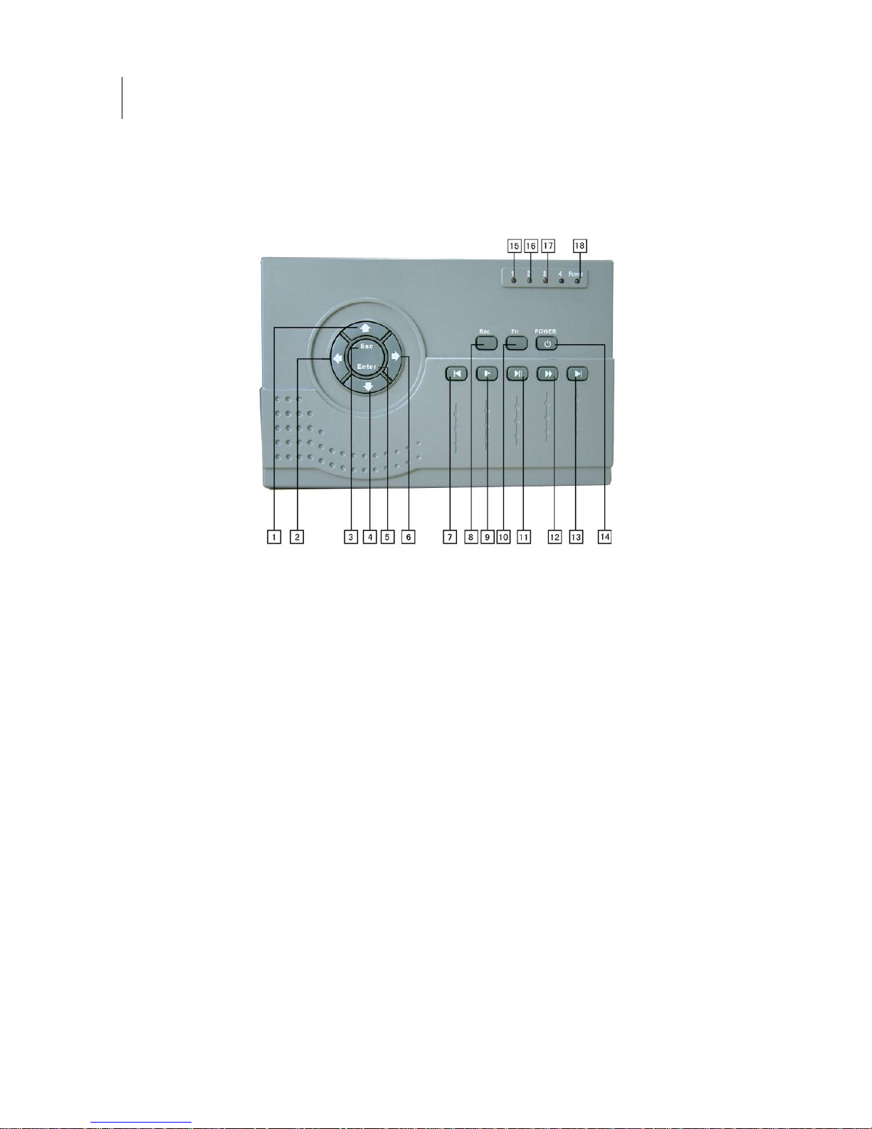
1.3 Front Panel
ATM04/ATM04D front panel is shown as in Figure 0-1.
Figure 0-1
1. Upper 2.Left 3. Esc
4. Down 5.Enter 6. Right
7. Previous 8. Record 9.Slow play
10. Assistant 11. Play/Pause 12.Fast forward
13. Next 14. On/off 15.The first channel indication light
16. The second channel indication light 17. The third channel indication light
18 Power indications light
ATM04/ATM04D is shown as in Figure 0-2.
14
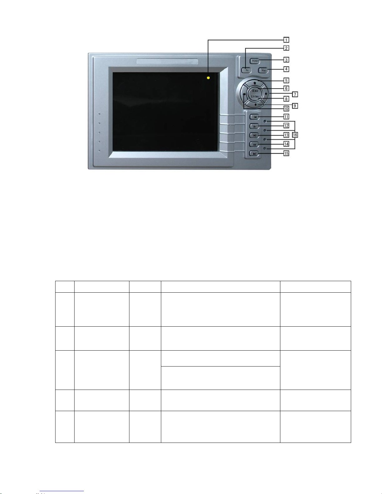
Figure 0-2
1. LCD 2.Assitant 3.LCD on/off
4. Record 5. Upper 6.Esc
7. Right 8.Enter 9.Down
10. Left 11.Previous 12.Slow play
13. Play/Pause 14.Fast forward 15.Next
16. Power and channel indication light
Please refer to the following sheet for more information. (Take ATM04D as an
example.)
S/N Name Icon Function Remark
7 Play previous
9 Slow play
11 Play/Pause
12 Fast forward
13 Play next
IW
XII
XI
When playback, click this button to
display previous file.
In menu operation, go to previous menu item,.
Various slow playback and normal
playback. Speeds.
Play/Pause
In real-time monitor mode, click this
button to go to search interface.
Various fast play and normal playback
Speeds.
In playback mode, play the next file.
In menu operation, go to the next menu item.
In numeral input mode,
click this button to input 1.
In numeral input mode,
click this button to input 2.
In numeral input mode,
click this button to input 3.
In numeral input mode,
click this button to input 4.
In numeral input mode,
click this button to input 5.
15

p
8 Record
10 Assistant
REC
Fn
Working with direction keys to enable/disable
record
In 1-window display mode, click this button to
go to assistant menu: PTZ control and Video
color.
Working with direction keys to realize motion
detection zone setup.
Clear function: Press Fn about 1.5 seconds to
clear all contents in current text box.
In preview mode (There is no other menu
available), press this button for 3 seconds to
switch between TV/VGA.
For HD1 series DVR, there are three modes:
TV/VGA/VGA LCD
(60Hz LCD output)
In text input mode, click this button
continuously to switch between
numeral/capitalized character and small
character(expansible )
3 Cancel ESC
5 Confirm Enter
S T
1/4
2/6
Direction keys
W X
Working with other keys to realize special
functions in some menu items.
Cancel
In playback mode, click this button to go back
to real-time monitor mode.
Confirm
Go to the main menu
In real-time monitor mode, click left/right
direction keys to switch between one-window
and multiple-windows.
Increase/decrease numeral
Modify setup
Switch PTZ control
In 1-window real-time monitor mode,
click up/down keys to switch monitor channel .
Switch PTZ control
In numeral input mode,
Click this button to input 0.
In numeral input mode,
Click S to input 6.
In numeral input mode,
Click T to input 7.
In numeral input mode,
Click W to input 8.
In numeral input mode,
Click X to in
ut 8.
1.4 Rear Panel
1.4.1 Overview
Please refer to Figure 0-3 for ATM04/ATM04D real panel information.
16
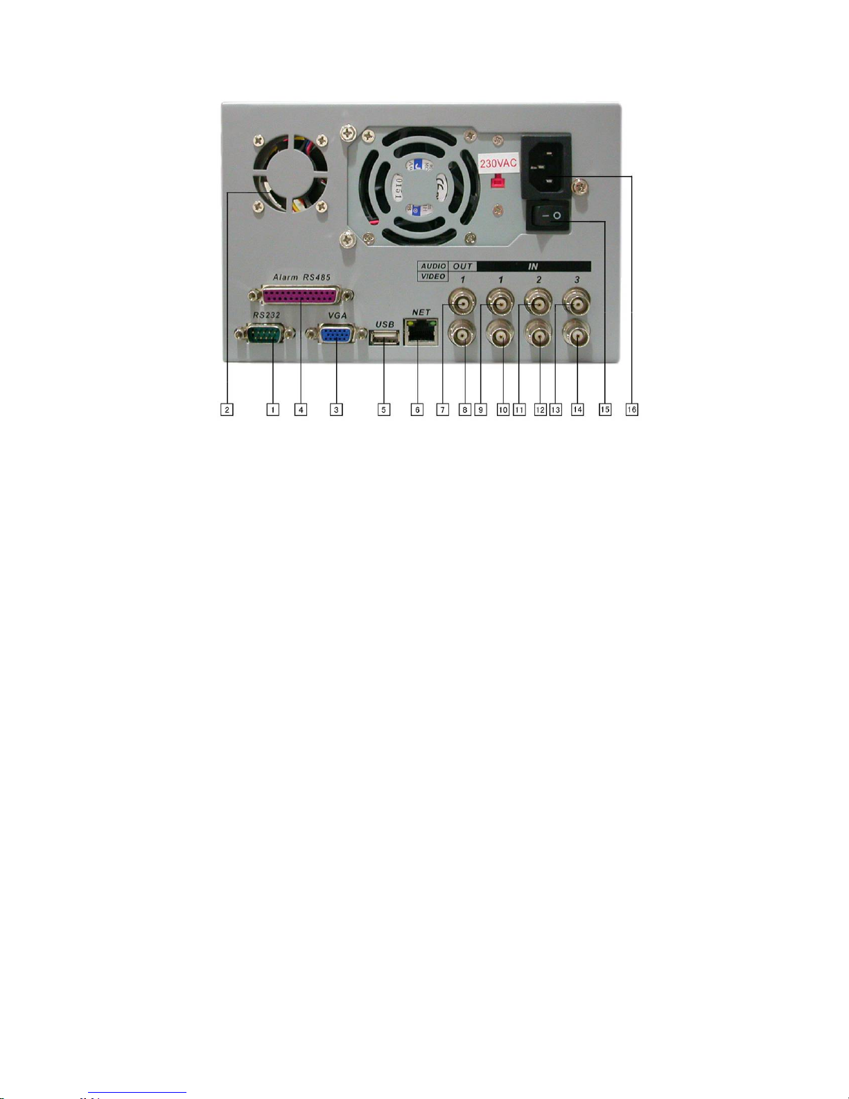
Figure 0-3
1. RS232 2.Fan 3.VGA
4. ALARM-RS485 Port 5.USB . 6. Network connection (RJ45)
7. Audio output 8.Video output 9.The first audio input channel
10. The first video input channel
11. The second audio input channel
12. The second video input channel
13. The third audio input channel (For 4-ch series DVR, it is the fourth video input channel.)
14. The third video input channel 15.Power button 16.Power socket
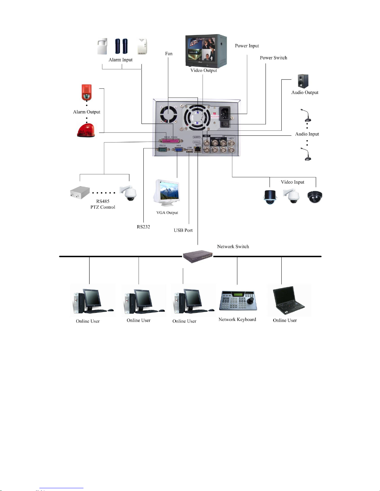
1.4.2 Connection Sample
Here is a connection sample of DVR0404MB/0404MBD for your reference. See
Figure 0-4.
17
1.5 Remote Control
The remote control interface is shown as in Figure 0-5.
Figure 0-4
18
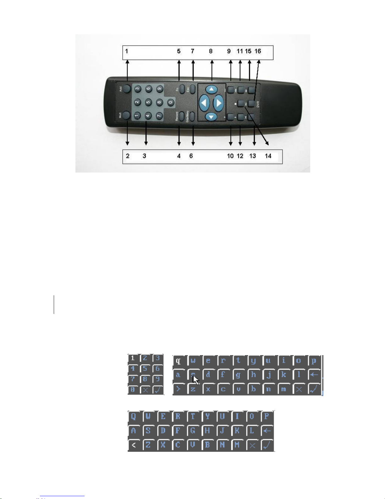
Figure 0-5
Serial Number Function
1 remote switch
2 Multiple-window switch
3 0-9 number key
4 Record
5 Auxiliary key
6 Confirm /menu key
7 Cancel
8 Direction key
9 forward
10 Previous
11 Back
12 Next
13 Slow play
14 Stop
15 Fast play
16 Play/Pause
Mouse Control
Left click mouse Have not login Pop up password input screen
Real-time surveillance mode Enter the main menu
In menu selection mode Enter the select item
In combo box Pop up pull down list
Click number box or pass word box Select number keyboard or character
keyboard
19

>: From small character to capitalized character
<: From capitalized character to small character
X: Delete all
Double left click mouse Implement current selection Such as double click one file name to
: Confirm the current value and close current panel
Surveillance mode:
playback the video
In single mode: change to
multiple-window surveillance mode
In multiple window mode: double
click one video to change to full-screen
display mode
Right click mouse Surveillance mode Pop up short cut menu
Press middle button In number box Increase or decrease number
Move mouse Select current controls
Drag mouse Select dynamic area
In menu setting Exit current menu without saving the
settings
In combo box Change selection
In menu screen Move cursor
In list box Move up and down
In PTZ menu Click one item to move menu
Virtual Keyboard & Front Panel
1.5.1 Virtual Keyboard Input Method
The system supports two input methods: numeral input and English character (small
and capitalized) input.
Move the cursor to the text column, the text is shown as blue, input button pops up
on the right. Click that button to switch between numeral input and English input
(capitalized and small), Use > or < to shift between small character and capitalized
character.
1.5.2 Front Panel Input Method
Move the cursor to the text column. Click Fn key and use direction keys to select
number you wanted. Please click enter button to input.
20

2 Installation and Connections
Note: All the installation and operations here should conform to your local
electric safety rules.
2.1 Check Unpacked DVR
When you receive the DVR from the shipping agency, please check whether there is
any visible damage to the DVR appearance. The protective materials used for the
package of the DVR can protect most accidental clashes during transportation. Then
you can open the box to check the accessories.
Please check the items in accordance with the list on the warranty card. Finally you
can remove the protective film of the DVR.
2.2 HDD Installation
2.2.1 Choose HDDs
We recommend Seagate HDD of 7200rpm or higher.
2.2.2 Calculate HDD Size
This series have no limit to HDD capacity. You can use 120G-750G HDD to
guarantee higher stability.
The formula of total HDD size is:
Total Capacity (MB) = Camera Amount * Recording Hours * HDD Usage Per Hour
(M/h)
H.264 compression is ideal for standalone DVRs. It can save more than 30% HDD
capacity than MPEG4. When you calculate the total HD capacity, you should
estimate the average HDD capacity per hour for each channel.
For example, for a 4-ch DVR, the average capacity of HDD usage per hour per
channel is 200M/h. Now if you hope the DVR can record the video 12 hours each
day for 30 days, the total capacity of HDDs needed is: 4 channels * 30 days * 12
hours * 200 M/h = 288G. So you need to install one 300G HDD or 2 160G HDDs.
2.2.3 HDD Installation
Data ribbons, fastening screws and smart HDD shelf design are already provided in
the accessories.
Notes: please pay attention to HDD jumper:
z If you just need to install one HDD, you can set the HDD to MASTER.
z If you install two HDDs to one IDE port, you need to set the farther one as
MASTER and the other as SLAVE. Please don’t set HDD as CS Enable or Cap
Limit.
Please follow the instructions below to install HDD.
21
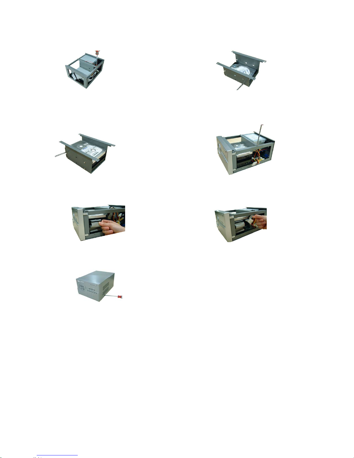
1. Loosen the screws. 2. Remove the unit cover.
3. Dismantle the HDD bracket. 4. Install the first HDD. Note the HDD is placed
upside down. Please make sure bracket is in
correct position.
5.
Install the second HDD on the bracket. 6. Fix the HDD bracket into the internal unit.
7. Connect HDD cable to IDE port 8. Connect power cord to the HDD.
9. Place the unit cover back and screws firmly.
After HDD installation, please check connection of data ribbon and power cord.
Note:
2.3 CD/DVD Burner Installation
For built-in burner, you can dismantle front plate to install CD burner. This built-in
burner should be set as MASTER.
For USB burners, you need to install USB series burner.
This series DVR is compatible with various burner brands popular in today’s market.
You can consult our local technical support or visit our website for more information.
22

2.4 Desktop and Rack Mounting
2.4.1 Desktop Mounting
To prevent surface damage, please make sure that the rubber feet are securely
installed on the four corners of the bottom of the unit.
Position the unit to allow for cable and power cord clearance at the rear of the unit.
Be sure that the air flow around the unit is not obstructed.
2.4.2 Rack Mounting
The DVR occupies two rack units of vertical rack space.
The hardware necessary to mount the DVR into a rack is supplied with the unit.
Install the cabinet in ventilated place. Avoid extreme heat, humid or dusty conditions.
You can use a soft dry brush to clean opening outlet, cooling fan and etc regularly.
2.5 Connecting Power Supply
Please check input voltage and device power button match or not.
We recommend you use UPS to guarantee steady operation, DVR life span, and
other peripheral equipments operation such as cameras.
2.6 Connecting Video Input and Output Devices
2.6.1 Connecting Video Input
The DVR automatically detects the video standard (PAL or NTSC) whenever you
connect a video input. It accepts color, black-and-white and analog video.
NOTE:
z Enabling line lock on cameras may cause video distortion. There may be noise in
the camera’s power source. If video from one or more cameras is distorted, we
recommend you disable line lock on the camera as your first troubleshooting step.
z If a video distribution amplifier is installed between the video source and the DVR,
do not set the output video level above 1 Vp-p.
To connect each video input:
1. Connect a coaxial cable to the camera or other analog video source.
2. Connect the coaxial cable to the video in connector on the rear panel.
Please refer to Figure 2-1 for more information.
NOTE:
You need to use a BNC installation tool to connect coaxial cables to the rear panel.
23
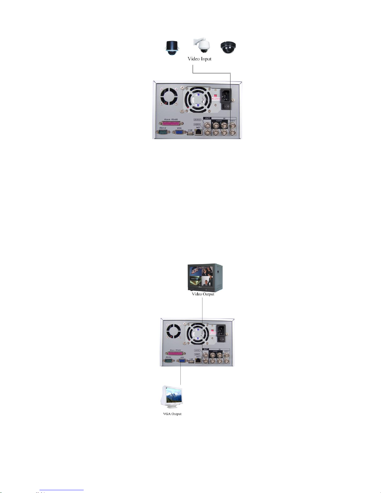
Figure 2-1
2.6.2 Connecting Video Output
This section provides information about physically connecting video display devices
to the DVR. See Figure 2-2.
If you connect the DVR with a TV monitor or VGA monitor, the DVR can automatically
detects the monitor type. And without any output device, by default, the DVR is
configured to use a TV monitor. In this case, if your application requires a VGA
monitor, you have to press the button “Fn” or Shift on the front panel to switch.
NOTE:
Video output 1 and VGA can’t display at the same time. But Video output 2 can
display properly with Video Output 1 or VGA.
Figure 2-2
24
2.7 Connecting Audio Input & Audio Output, Alarm Input &Alarm Output,
RS232/RS485 and Other Interfaces
ATM04 has 3-ch audio input, 1-ch audio output, 4-ch alarm input and 3-ch alarm
output.
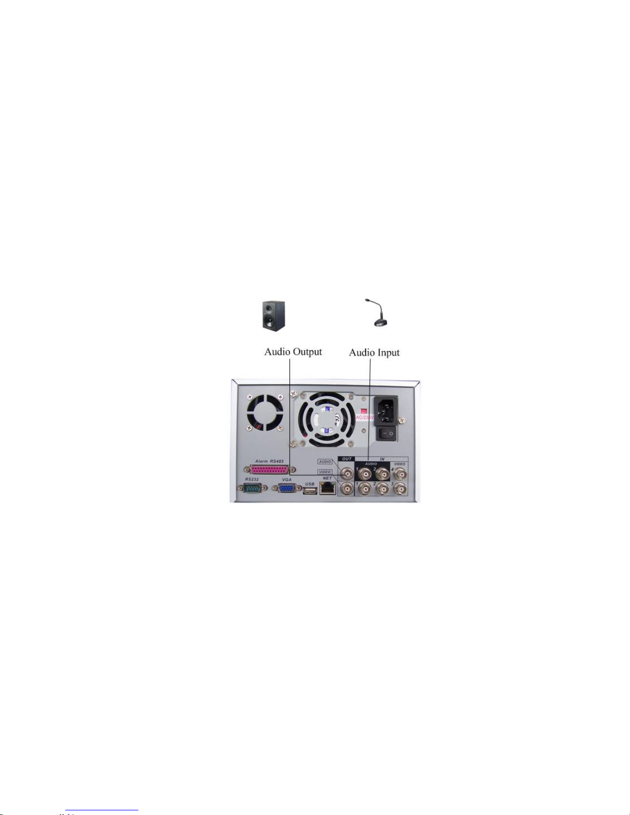
2.7.1 Audio Input/Audio Output
The DVR encodes audio and video signals simultaneously, which lets you control
audio at the monitored location.
To set up audio:
1. Make sure your audio input device matches the RCA input level. If the device and
RCA input levels do not match, audio distortion problems may occur.
2. Make sure the audio connector is wired as follows:
3. Connect a line input device or pre-amplified microphone to the audio connector for
the video channel on the rear panel.
Please refer to Figure 2-3.
Figure 2-3
2.7.2 Alarm Input and Relay Output
The DVR offers 4-ch alarm input for external signaling devices, such as door contacts
or motion detectors. Each alarm input can be either normally open or normally closed.
Once configured, an alarm input can invoke many different activities, including
triggering a relay device, sending an alert to a security office or storing pre-alarm
video to the DVR.
2.7.3 Alarm Input
You should check your alarm input mode is grounding alarm input or not.
For this series DVR, grounding signal is needed for alarm input.
If you need to connect two units or one DVR and other device, please use relay to
separate them.
Please refer to Figure 2-4 for more information.
25
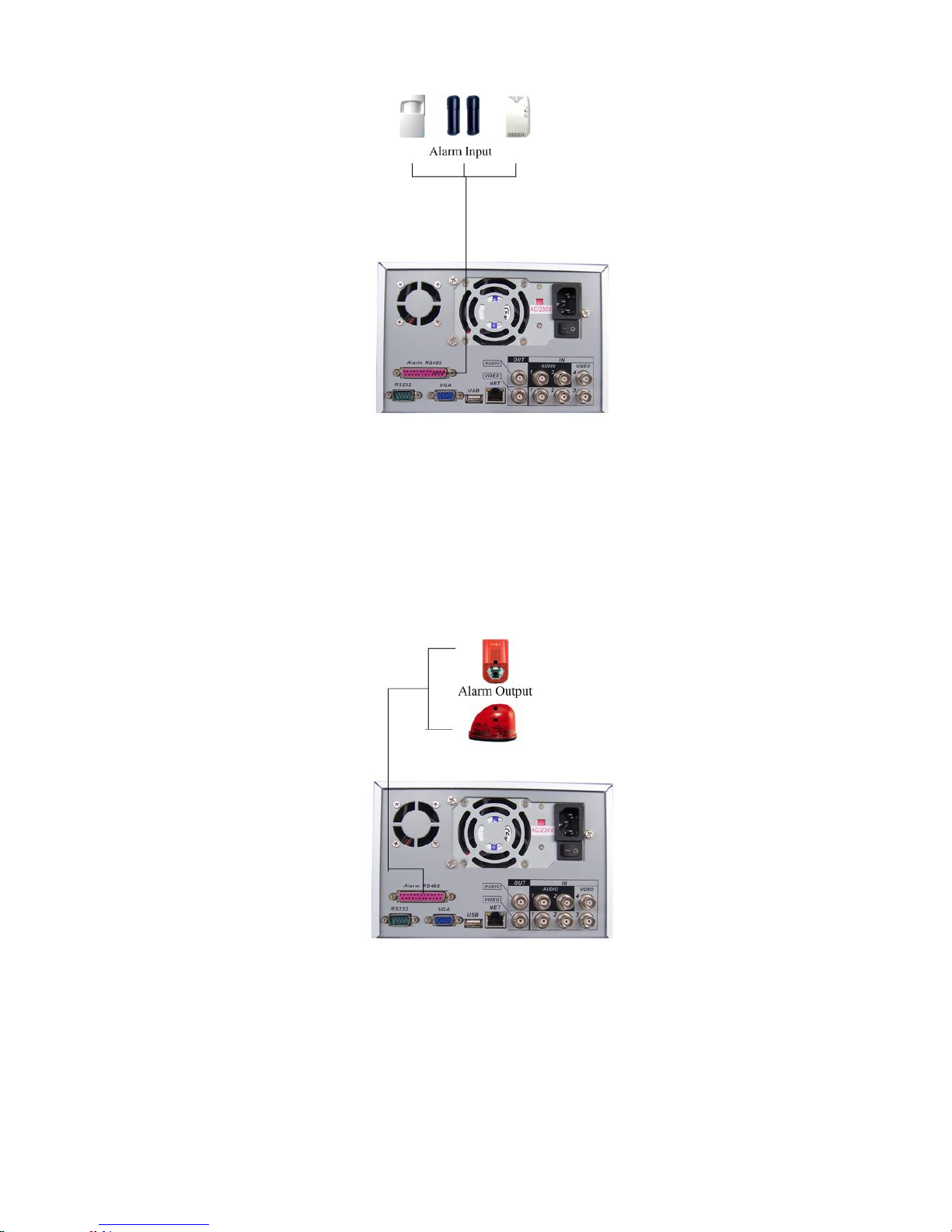
Figure 2-4
2.7.4 Alarm Output
Do not connect alarm output port directly with high power load (no more than 1 A) in
case of heavy current.
You can use the co-contactor to realize the connection between the alarm output port
and the load.
Please refer to Figure 2-5 for more information.
2.7.5 Alarm Input and Output Details
You can refer to the following sheet and Figure 2-6 for alarm input and output
information.
Figure 2-5
26

Terminal
Screw
Figure 2-6
Parameter
Grounding Alarm
Ground Ground line
Alarm in 1…4 1, 2, …, 4. Become activated in low voltage,
Relay Output 1,2,3,4: NO and C(Normally Open and Com)
5: NO,C and NC(Normally Open, Com, Normally Closed)
6: Ctrl 12V(This is used for reset the senor)
485 A、B
485 communication port. They are used to control devices
such as PTZ.
+12(C)
This should input an external power input(Less than 1 A).
z 4-ch grounding alarm inputs. (Normal open or Normal close type)
z Please parallel connect COM end and GND end of the alarm detector (Provide
external power to the alarm detector).
z Please parallel connect the Ground of the DVR and the ground of the alarm
detector.
z Please connect the NC port of the alarm sensor to the DVR alarm input(ALARM)
z If you need to reset the touched-off alarm remotely, you can use DVR to supply
controllable 12 V power to the alarm detector such as the smoke detector.
z Use the same ground with that of DVR if you use external power to the alarm
device.
27
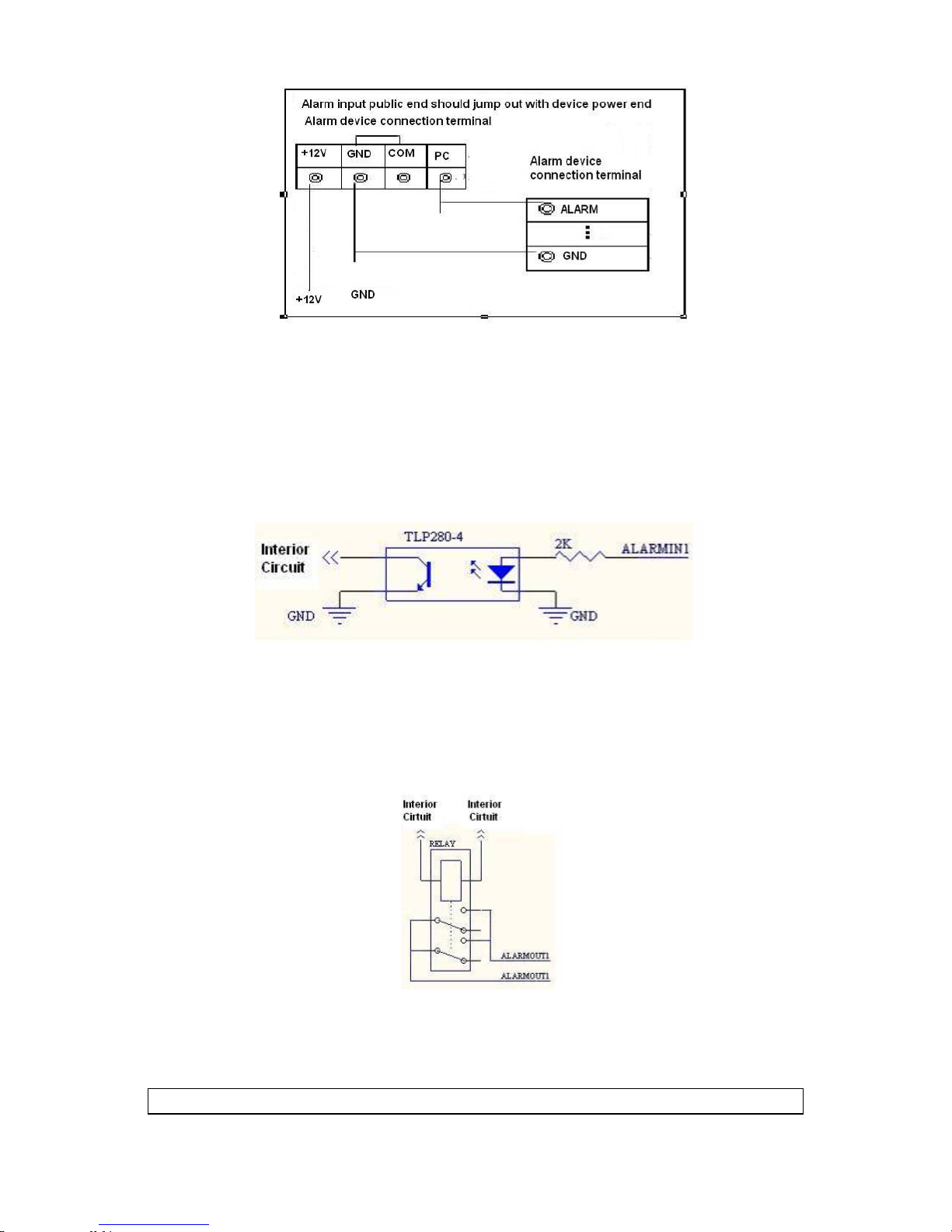
Figure 2-7
2.7.6 Relay Output Description
z 3 ways relay alarm output. Provide external power to external alarm device.
z To avoid over loading, please read the following relay parameters sheet carefully.
(See below table)
z The controllable +12v can be used to restore the smoke detector.
Please refer to Figure 2-8 for alarm input module information.
Figure 2-8
Please refer to Figure 2-9 for alarm output module information.
Figure 2-9
Relay Specification
Model:
JRC-27F
28

Material of
the contact
Rating
(resistance
load)
Insulation between contacts with
Surge
voltage
Length of
open time
Length of
close time
Longevity
Temperature -40 ~+70
Silver
Rated switch capacity 30VDC 2A, 125VAC 1A
Maximum switch power 125VA 160W
Maximum switch voltage 250VAC, 220VDC
Maximum switch currency 1A
same polarity
between contacts with
different polarity
between contact and
winding
between contacts with
same polarity
3ms max
3ms max
Mechanical 50×106 times (3Hz)
Electrical 200×103 times (0.5Hz)
1000VAC 1minute 50/60Hz
1000VAC 1minute 50/60Hz
1000VAC 1minute 50/60Hz
1500V (10×160us)
2.8 RS232
You can connect the DVR with POS or Keyboard through RS232.
With POS system, the DVR can communicate through RS232 and network. For the
POS system, the DVR can integrate the text content and even search the record
through the info.
The series DVR also support NKB operation. You can operate the DVR from the
keyboard controls instead of using the control pad on the front panel of the unit.
To connect a NKB keyboard to the DVR:
1. Assemble the KBD keyboard according to the instructions in its accompanying
installation manual.
2. Connect the KBD keyboard into one of the RS232 ports on the DVR or through
network.
2.9 RS485
When the DVR receives a camera control command, it transmits that command up
the coaxial cable to the PTZ device. RS485 is a single-direction protocol; the PTZ
device can’t return any data to the unit. To enable the operation, connect the PTZ
device to the RS485(A,B) input on the DVR. Since RS485 is disabled by default for
each camera, you must enable the PTZ settings first. This series DVRs support
multiple protocols such as Pelco-D, Pelco-P.
To connect PTZ devices to the DVR:
1. Connect RS485 A,B on the DVR rear panel.
2. Connect the other end of the cable to the proper pins in the connector on the
camera.
29
3. Follow the instructions for configuring a camera to enable each PTZ device on the
DVR.
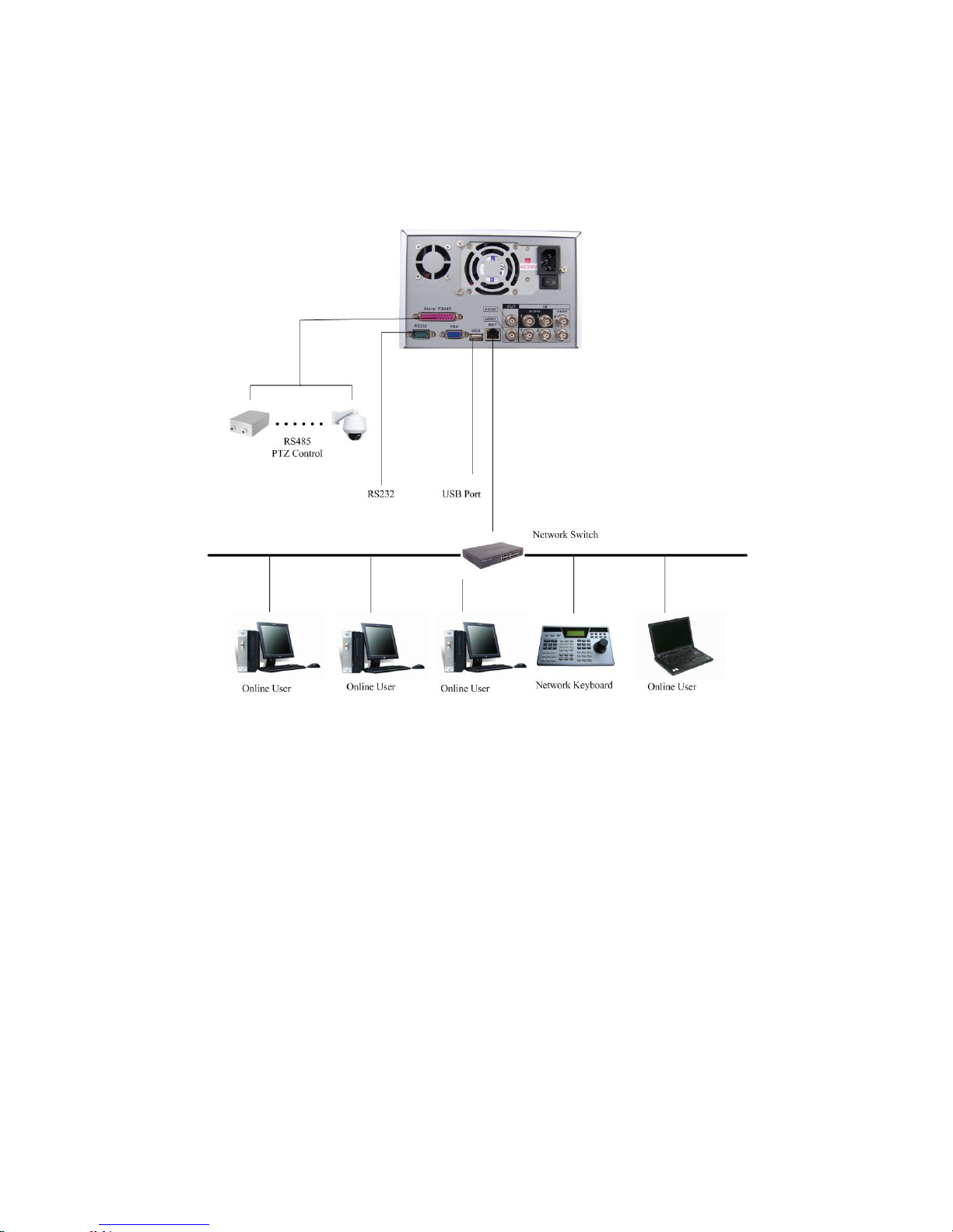
2.10 Other Interfaces
There are still other interfaces on the DVR, such as USB ports. You can refer to
the Figure 2-10 for more information.
Figure 2-10
30
 Loading...